EP2944486B1 - Dispositif et procédé d'entretien d'une climatisation - Google Patents
Dispositif et procédé d'entretien d'une climatisation Download PDFInfo
- Publication number
- EP2944486B1 EP2944486B1 EP15165998.4A EP15165998A EP2944486B1 EP 2944486 B1 EP2944486 B1 EP 2944486B1 EP 15165998 A EP15165998 A EP 15165998A EP 2944486 B1 EP2944486 B1 EP 2944486B1
- Authority
- EP
- European Patent Office
- Prior art keywords
- pressure side
- region
- low
- pressure
- air conditioner
- Prior art date
- Legal status (The legal status is an assumption and is not a legal conclusion. Google has not performed a legal analysis and makes no representation as to the accuracy of the status listed.)
- Active
Links
- 238000000034 method Methods 0.000 title claims description 44
- 238000012423 maintenance Methods 0.000 title description 2
- 239000012530 fluid Substances 0.000 claims description 42
- 239000002826 coolant Substances 0.000 claims description 25
- CURLTUGMZLYLDI-UHFFFAOYSA-N Carbon dioxide Chemical compound O=C=O CURLTUGMZLYLDI-UHFFFAOYSA-N 0.000 claims description 15
- 235000011089 carbon dioxide Nutrition 0.000 claims description 13
- 238000005086 pumping Methods 0.000 claims description 13
- 239000007788 liquid Substances 0.000 claims description 9
- 238000002156 mixing Methods 0.000 claims description 7
- 230000006835 compression Effects 0.000 claims description 2
- 238000007906 compression Methods 0.000 claims description 2
- 238000010438 heat treatment Methods 0.000 claims description 2
- 239000003507 refrigerant Substances 0.000 description 51
- 239000003921 oil Substances 0.000 description 46
- 238000004378 air conditioning Methods 0.000 description 29
- 230000008878 coupling Effects 0.000 description 15
- 238000010168 coupling process Methods 0.000 description 15
- 238000005859 coupling reaction Methods 0.000 description 15
- 238000005259 measurement Methods 0.000 description 15
- 239000002699 waste material Substances 0.000 description 9
- 238000010586 diagram Methods 0.000 description 5
- 239000010725 compressor oil Substances 0.000 description 4
- 238000004891 communication Methods 0.000 description 3
- 239000000203 mixture Substances 0.000 description 3
- 238000004064 recycling Methods 0.000 description 3
- 239000010726 refrigerant oil Substances 0.000 description 3
- 238000001816 cooling Methods 0.000 description 2
- 238000010587 phase diagram Methods 0.000 description 2
- 230000003134 recirculating effect Effects 0.000 description 2
- XLYOFNOQVPJJNP-UHFFFAOYSA-N water Substances O XLYOFNOQVPJJNP-UHFFFAOYSA-N 0.000 description 2
- 238000005303 weighing Methods 0.000 description 2
- FNYLWPVRPXGIIP-UHFFFAOYSA-N Triamterene Chemical compound NC1=NC2=NC(N)=NC(N)=C2N=C1C1=CC=CC=C1 FNYLWPVRPXGIIP-UHFFFAOYSA-N 0.000 description 1
- 230000015572 biosynthetic process Effects 0.000 description 1
- 230000003750 conditioning effect Effects 0.000 description 1
- 239000000356 contaminant Substances 0.000 description 1
- 230000007547 defect Effects 0.000 description 1
- 230000001419 dependent effect Effects 0.000 description 1
- 238000007599 discharging Methods 0.000 description 1
- 238000000605 extraction Methods 0.000 description 1
- 230000002349 favourable effect Effects 0.000 description 1
- 238000010327 methods by industry Methods 0.000 description 1
- 238000012986 modification Methods 0.000 description 1
- 230000004048 modification Effects 0.000 description 1
- 238000000926 separation method Methods 0.000 description 1
- 238000012360 testing method Methods 0.000 description 1
- 239000010913 used oil Substances 0.000 description 1
Images


Classifications
-
- B—PERFORMING OPERATIONS; TRANSPORTING
- B60—VEHICLES IN GENERAL
- B60H—ARRANGEMENTS OF HEATING, COOLING, VENTILATING OR OTHER AIR-TREATING DEVICES SPECIALLY ADAPTED FOR PASSENGER OR GOODS SPACES OF VEHICLES
- B60H1/00—Heating, cooling or ventilating [HVAC] devices
- B60H1/00507—Details, e.g. mounting arrangements, desaeration devices
- B60H1/00585—Means for monitoring, testing or servicing the air-conditioning
-
- F—MECHANICAL ENGINEERING; LIGHTING; HEATING; WEAPONS; BLASTING
- F25—REFRIGERATION OR COOLING; COMBINED HEATING AND REFRIGERATION SYSTEMS; HEAT PUMP SYSTEMS; MANUFACTURE OR STORAGE OF ICE; LIQUEFACTION SOLIDIFICATION OF GASES
- F25B—REFRIGERATION MACHINES, PLANTS OR SYSTEMS; COMBINED HEATING AND REFRIGERATION SYSTEMS; HEAT PUMP SYSTEMS
- F25B45/00—Arrangements for charging or discharging refrigerant
-
- F—MECHANICAL ENGINEERING; LIGHTING; HEATING; WEAPONS; BLASTING
- F25—REFRIGERATION OR COOLING; COMBINED HEATING AND REFRIGERATION SYSTEMS; HEAT PUMP SYSTEMS; MANUFACTURE OR STORAGE OF ICE; LIQUEFACTION SOLIDIFICATION OF GASES
- F25B—REFRIGERATION MACHINES, PLANTS OR SYSTEMS; COMBINED HEATING AND REFRIGERATION SYSTEMS; HEAT PUMP SYSTEMS
- F25B9/00—Compression machines, plants or systems, in which the refrigerant is air or other gas of low boiling point
- F25B9/002—Compression machines, plants or systems, in which the refrigerant is air or other gas of low boiling point characterised by the refrigerant
- F25B9/008—Compression machines, plants or systems, in which the refrigerant is air or other gas of low boiling point characterised by the refrigerant the refrigerant being carbon dioxide
Definitions
- the invention relates to a device for servicing an air conditioner, in particular for air conditioners, which use as refrigerant C0 2 or R744, wherein the device has a low-pressure side, which is connectable via a low-pressure side coupling to a service port on the low pressure side of the air conditioning, and a high-pressure side Region, which is connectable via a high-pressure side coupling to a service port on the high-pressure side of the air conditioner, wherein between the low-pressure side region and the high-pressure side region, a compressor is provided. Furthermore, the invention relates to a method for operating a service unit for air conditioners.
- an air conditioning service has the task to empty the air conditioning system, to evacuate and then to refill with the correct amount of refrigerant and oil.
- Modern service equipment such as are used for automotive air conditioning systems, usually have two service connections, one is connected to the high pressure side of the air conditioning, and the other to the low pressure side. Thereby, a circuit is formed, which usually leads from the low-pressure side connection via an oil separator, an evaporator, a compressor and a condenser to the high-pressure side connection.
- the service unit further emptying and filling facilities are provided for sucking the mixture of refrigerant and compressor oil from the refrigerant circuit and to refill the air conditioning with refrigerant and compressor oil.
- the cycle mixture via a separation stage, for.
- a separation stage for.
- the circulation system is largely emptied by means of a vacuum pump and then fed to the system from a storage container new refrigerant and fresh oil.
- systems and methods for servicing air conditioning systems are off WO 2011/088831 A1 .
- DE 202008003123 U1 or DE 102009054436 A1 known.
- a device according to the preamble of claim 1 is characterized by the US5167126 disclosed.
- the refrigerant when rapidly expanding in the wet steam region, is below a threshold pressure can solidify.
- the threshold at which the C0 2 solidifies in the wet steam to dry ice at a pressure of 5.18 bar.
- a relaxation to about 18 bar and then wait until the C0 2 in the vehicle has completely evaporated before the extraction can be continued.
- the present invention is based on the idea to provide an apparatus and a method by which the aforementioned problems of the prior art alleviated who the.
- the time required to empty the air conditioner should be shortened by the invention.
- an overpressure region is provided between the compressor and the high-pressure-side region, which region is connected to the high-pressure-side region via a throttle element.
- the achievable overpressure allows a more efficient process engineering use of the area outside the wet steam curve of the refrigerant on the gas side of the phase diagram.
- throttle means in the context of this invention, any device is referred to, which can exert the pressure-regulating function of a throttle. These include, for example, an expansion valve, a fixed throttle, an orifice with or without bypass, etc.
- a vacuum pump can be connected to the low-pressure side region, with which the fluid system of the system or individual regions thereof can be evacuated.
- a circulation fluid connection on the low pressure side region, the compressor, the overpressure region, the throttle body, and the high pressure side region to the high pressure side coupling can be released from the low-pressure side coupling by means of valves a circulation fluid connection on the low pressure side region, the compressor, the overpressure region, the throttle body, and the high pressure side region to the high pressure side coupling.
- This recirculating fluid connection makes it possible to very quickly condition the coolant in the system in a circulatory process in such a way that the formation of dry ice is prevented during deflation.
- a reservoir can be provided in a storage area, which can be connected via valves to the overpressure area and / or the low-pressure-side area.
- the reservoir is used both for storing the pumped-off coolant, as well as for providing the coolant to be pumped.
- a pumped-in fluid connection can be released via the compressor, the overpressure region and the high-pressure-side region to the high-pressure-side coupling.
- the coolant can be pumped from the reservoir by means of the compressor via the high-pressure side connection in the air conditioner.
- the coolant can be cooled in the overpressure region with a gas cooler and the amount pumped in be measured with a flow measurement.
- discharge valves can be connected to the low-pressure-side region and / or the high-pressure-side region according to the invention. This allows the refrigerant, e.g. CO2, to discharge into the environment.
- refrigerant e.g. CO2
- a fresh oil tank can be connected via a fresh oil valve to the fluid system. This allows you to easily refill fresh oil in the air conditioner.
- the term "fluid system” refers to the entirety of all lines and components of the device and optionally the air conditioning system connected thereto, in which the fluid of the refrigerant can be located or through which the refrigerant can flow.
- An oil separator and / or an evaporator and / or a filter drier may preferably be provided in the low-pressure side region, and a liquid separator and / or a gas cooler and / or a flow measurement may be provided in the overpressure region.
- An advantageous embodiment of the device according to the invention can provide that in the overpressure region between the compressor and the gas cooler, a changeover valve is provided, with which the circulation fluid connection can be diverted to a bypass bypassing the gas cooler.
- a single compressor can thus be used both for the circulation step (via the bypass), as well as for pumping down and for pumping the coolant (in each case via the gas cooler).
- the inventive method for operating a service unit for air conditioners, in particular for air conditioning systems that use CO 2 or R744 as refrigerant is characterized in that the service unit for forming a circuit via a low-pressure side coupling and a high-pressure side coupling to the low pressure side and the high pressure side the air conditioning system is connected, wherein the method comprises the step of converting the refrigerant in the air conditioner of a phase state II within the wet steam curve by means of a cycle process in a phase state II E outside the wet steam curve, wherein in phase state II E, the specific enthalpy has a value, whose isenthalpe is completely outside the dry ice area. From the phase state II E starting the refrigerant can be removed without forming dry ice.
- a "process of circulation” is an operation in which the coolant is circulated in a cycle. With regard to the phase changes, this is not a closed cycle because the desired end point of the state change (phase state II E ) does not coincide with the initial state (phase state II).
- the circulation process could for example be carried out by a simple circulation system with a gas pump and a heat supply, for example a heat exchanger, since this would be sufficient to increase the enthalpy of the refrigerant.
- particularly advantageous is the use of the device according to the invention for servicing an air conditioning system described herein.
- the cycle process starting from phase state II may comprise the following state changes: substantially isobaric heating of the refrigerant up to the wet steam curve, substantially isentropic compression to an overpressure above the pressure of the initial phase state II and preferably above the critical pressure of the refrigerant, im Essentially, isenthalpe expansion, and mixing with the refrigerant in the air conditioner.
- the method of the invention may include the steps of: evacuating a sealed portion of the service device that connects to and is separated from the low pressure side of the air conditioner by a closed valve and opens a fluid communication between the evacuated portion of the service device and the fluid system the air conditioning.
- the cycle process can be started from a favorable phase state II, which results after a first expansion of the coolant.
- the method may include the step of pumping the refrigerant from the air conditioner into a reservoir.
- the refrigerant may either be completely drained or stored for recycling.
- waste oil can be separated during the process and the amount of waste oil separated from the air-conditioning system can be determined. This can be concluded on the amount of fresh oil to be replenished in the air conditioning.
- a further advantageous embodiment of the method may include the step of evacuating the system with a vacuum pump after draining and possibly pumping off the refrigerant.
- the evacuation of the system allows a density test. At the same time any water present in the system is evaporated and removed from the circulation.
- fresh oil can be introduced into the evacuated fluid system in an advantageous manner, wherein the amount of fresh oil can be determined based on the amount of the separated waste oil.
- a simple and accurate dosage of fresh oil through a simple valve is possible. No pump is required as the fresh oil is sucked in by the vacuum. The oil is taken with the subsequent filling of the refrigerant and thus enters the air conditioning.
- Fig. 1 shows an embodiment of the service device in a circuit diagram, wherein the fluid system of the device can be divided into substantially four areas, a low-pressure side area A, an overpressure area B, a high-pressure side area C and a storage area D.
- the low-pressure side region A starts at the low-pressure side clutch 1, with which the service device is connected to the low-pressure side of the vehicle air conditioner.
- the line preferably runs in a hose up to a first shut-off valve 101, wherein in front of the shut-off valve 101 measuring devices 16 are provided for the pressure and the temperature.
- the shut-off valve 101 is closed, and the meters 16 substantially measure the values for the low-pressure side air-conditioner of the air conditioner.
- an oil separator 2 is arranged and after a further shut-off valve 102, the line via an evaporator 3 and a filter drier 11 to another valve 103, which can be regarded as the end of the low-pressure side region A.
- the oil separated from the oil separator 2 from the air conditioner is collected in a waste oil collecting tank 14 and weighed with a balance to determine the amount of oil to be replenished.
- shut-off valve 106 which is provided as a boundary to the storage area D.
- the second connection leads via a shut-off valve 109 to a vacuum pump 10.
- a further connection is provided, which leads to a first discharge valve V1, via which the refrigerant can be discharged to the environment.
- a compressor 4 is provided, which opens into the overpressure region B.
- a liquid separator 12 is provided after the compressor 4, which serves to recover oil and resources of the compressor, which are carried by the coolant, and to supply the compressor again.
- the safety valve 13 limits the system pressure in order to counteract possible damage caused by possible defects and thus excessive pressure.
- the fluid flow through a switching valve 6 can be guided either via a flow measurement 8 and a gas cooler 7, or via a bypass 17, which bypasses the flow measurement and the gas cooler.
- a shut-off valve 104 At the end of the overpressure region B is still a shut-off valve 104, and after this line leads to a throttle body 5, which is arranged between the overpressure region B and the subsequent high-pressure side region C. Between the shut-off valve 104 and the throttle body 5, a connection is provided, which leads to a second drain valve V2.
- a throttle body 5 As a throttle body 5, a controlled expansion valve is used in the illustrated embodiment.
- the throttle body can also be realized in another way, for example by an orifice with or without bypass, or a fixed throttle in conjunction with a variable-speed compressor.
- the beginning of the throttle body 5 high-pressure side region C has a shut-off valve 105 and measuring devices 16 ', can be measured via the pressure and temperature of the supply hose to the high pressure side of the air conditioner. Between the throttle body 5 and the shut-off valve 105, a connection is provided which leads via a fresh oil valve 110 to a fresh oil tank 15.
- the high-pressure side region C ends at the high-pressure side Coupling 1 ', with which the service device is connected to the high pressure side of the air conditioner.
- circulating fluid connection 201 This path will be referred to as circulating fluid connection 201 hereinafter, and is in FIG Fig. 2A again shown schematically and clearly simplified. Together with the conduits of the air conditioner, the circulating fluid communication 201 provides a continuous circulatory system.
- circulation fluid connection 201 bypasses the gas cooler 7 arranged in the overpressure region by switching the changeover valve 6 to the bypass 17.
- the functional significance of the recirculating fluid connection 201 will be explained in more detail in connection with the description of the method according to the invention.
- the fourth area of the device is the storage area D, which essentially consists of a storage container 9 and a weighing unit 19 attached thereto.
- the opening into the reservoir 9 line can be shut off with a shut-off valve 108.
- a first line leads via the shut-off valve 106 to the low-pressure-side area A, and a second line leads via a shut-off valve 107 to the overpressure area B, wherein this line opens at the outlet of the gas cooler 7.
- valves 101-110, V1 and V2, as well as the change-over valve 6 can be used to provide a variety of different fluid connections through the elements and conduits of the present invention Fig. 1 realize realized device.
- a pump down fluid connection 202 can be produced, via which the refrigerant from the air conditioning system from the compressor 4 via the gas cooler 7 can be pumped into the reservoir 9.
- the pump down fluid connection 202 is shown schematically in FIG Fig. 2B shown.
- a single-pumping fluid connection 203 can be produced, via the compressor 4 refrigerant from the reservoir 9 via the flow measurement 8, the gas cooler 7 and the throttle body 5 in the high pressure side of the air conditioning can be pumped.
- the pump-in fluid connection 203 is shown schematically in FIG Fig. 2C shown.
- the low-pressure side clutch 1 and the high-pressure side clutch 1 ' are connected to corresponding service ports of the automotive air conditioner, the connection valves 101 and 105 being closed.
- the low-pressure-side coupling 1 and the high-pressure-side coupling 1 ' are each located at the end of a connection hose 20, 20', with which the service connections in the car can be easily reached.
- a combination connection can also be used with which both connections can be connected simultaneously to the air conditioning system in a single step.
- the CO2 in the air conditioner after having reached equilibrium at room temperature (about 20 ° C), has a pressure in the range of about 60 bar.
- the degree of filling of the system is in a full automotive air conditioning usually way in a range of up to 260 kg / m 3 or optionally below.
- the operating pressures of the air conditioner when servicing the system play no role, since the air conditioning compressor (as well the gas cooler and the air conditioner evaporator) is deactivated during service. Therefore, when used in the context of this application, the term "high-pressure side of the air conditioner", so it is meant only the line section of the air conditioner, which is between the compressor and the throttle of the air conditioning, and the gas cooler and, in the case of CO2 than Coolant, the internal heat exchanger of the cooling system runs.
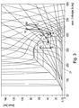
- the compressor when stopped, substantially the same pressure and phase condition will quickly build up throughout the air conditioning circuit. This phase state at rest is in the present example at about 20 ° C, 250 kg / m 3 and 57 bar and is in the phase diagram of Fig. 3 designated as point I.
- the inner valve 102 and the vacuum pump valve 109 are opened and the volume of the oil separator 2 is evacuated with the vacuum pump. Thereafter, after closing the vacuum pump valve 109, the port valve 101, which causes the refrigerant of the air conditioner to flow into the oil separator.
- the occurring state change is in the diagram of Fig. 3 to recognize as an isenthalpe expansion between points I and II. In the example shown, point II is approximately -2 ° C and 33 bar, with approximately a doubling of the volume.
- the waste oil entrained by the refrigerant is separated and collected in a waste oil container 14.
- the amount of collected waste oil can be determined for example via a balance.
- the CO2 isobarically heated out of the wet steam curve (state change from point II to point III in FIG Fig. 3 ) and then passes through a filter drier to remove any contaminants or moisture.
- the refrigerant has in the present example at point III a pressure of about 33 bar and a temperature of about 15 ° C.
- the refrigerant is substantially isentropically compressed to a supercritical pressure of about 90 bar, wherein the pressure of the throttle body 5 is controlled (change of state from point III to point IV in Fig. 3 ).
- the temperature at point IV is about 100 ° C.
- the liquid separator 12 serves to entrain entrained oil of the compressor 4 again.
- the refrigerant passes, bypassing the gas cooler 7, directly to the throttle body 5, where there is an isenthalpic expansion (from point IV to point V in Fig. 3 ) comes to a pressure of about 67 bar and a temperature of about 80 ° C.
- the air conditioning system In the air conditioning system, it then mixes with the refrigerant, which is located in the accumulator of the air conditioner, and initially the output phase state (point II in Fig. 3 ) having.
- the phase state in the air conditioner changes at a constant density, shifting to the mixing point II, which is plotted in the diagram at about 4 ° C. and about 38 bar, for example.
- the mixing point II Represents only a virtual point, since in the actual cycle process this point shifts steadily along the isodens (approximately at 125 kg / m 3 ).
- the circulation process is carried out until a phase state according to point II E is reached in the air conditioning system, this point lying at an enthalpy whose isenthalpe lies completely outside the dry ice region 21.
- the exact location of the end point 11 E is highly dependent on the initial degree of filling of the plant and is preferably at a specific enthalpy of about 450 kJ / kg or above.
- the CO 2 can be drained and pumped out without the coolant would freeze.
- a pair of values for the pressure and the temperature in the circuit can be read during the circulation process, from which it can be determined whether a sufficient enthalpy for the discharge has already been reached at the predetermined filling level. It is not absolutely necessary to know exactly the actual degree of filling (ie the density) of the system. If one uses the maximum degree of filling as the reference value for the method, the same cycle process, if the degree of filling would actually be lower, would only lead to an end point II E with a higher enthalpy, so that further no icing in the subsequent draining step is to be feared.
- Discharging can be done by opening the drain valves V1, V2, but it is also possible with the device according to the invention to collect the refrigerant and make it available for reuse.
- the inner valve 104 is closed between the overpressure region B and the high-pressure-side region C, and the switching valve 106 is switched to the side of the gas cooler 7.
- an exhaust fluid connection 202 can be provided, starting from the low-pressure side clutch 1 via the oil separator 2, the evaporator 3, the filter dryer 11, the compressor 4, the liquid separator 12, the Changeover valve 6, the flow measurement 8 and the gas cooler 7 leads to the reservoir 9.
- the compressor 4 can now pump the refrigerant via the low-pressure side coupling 1 from the cycle of the air conditioner in the reservoir.
- the reservoir valve 108 is closed and remaining CO2 discharged through the drain valves V1 and V2 until the pressure in the system has dropped to ambient pressure. Thereafter, the port valves 101, 105, the inner valves 102, 103, 104 and the vacuum pump valve 109 are opened and the system is evacuated via the vacuum pump 10, wherein the vacuum pump, a pressure in the order of about 1 mbar can be achieved. At this pressure, any water present in the system also evaporates and is sucked off via the vacuum pump 10 together with the remaining refrigerant.
- the amount of compressor oil collected in the waste oil collecting 14 is measured and introduced a corresponding amount of fresh oil by metered opening of the fresh oil valve 110 from the fresh oil tank 15 in the high-pressure side region C.
- the prevailing vacuum in the system causes the oil to be sucked into the system without further ado.
- the oil is then flushed by the incoming refrigerant in the circuit of the air conditioner.
- the inner valves 103, 104 and 105 are then opened and the changeover valve is switched in the direction leading to the gas cooler 7 direction. Further, the low-pressure side shut-off valve 106 and the reservoir valve 108 are opened, so that the one-pumping fluid communication 203 is produced, from the reservoir 9 via the filter drier 11, the compressor 4, the liquid separator 12, the switching valve 6, the check valve 18, the throttle body 5 and the high-pressure side clutch 1 'leads to the high-pressure side of the air conditioner.
- the compressor 4 pumps CO 2 from the reservoir via the pump-in fluid connection 203 into the air conditioner, wherein the amount of the pumped refrigerant is measured in the flow measurement 8 to fill the required amounts of refrigerant according to the manufacturer in the air conditioner.
- the high pressure of the compressor is controlled by the throttle body 5.
- the port valve 105 After filling, the port valve 105 is closed and the clutches 1 and 1 'are released from the service ports of the air conditioner.
- the device according to the invention can also be embodied in numerous other ways.
- the arrangement of elements can be changed and certain elements can also be completely removed, as long as this does not affect the functionality of the device and the implementation of the method according to the invention.
- the arrangement of the oil separator 2 and the evaporator 3 could be reversed without affecting the functionality.
- the flow measurement 8 is not absolutely necessary, since the filling amount can also be determined in other ways, as is known in the art, for example by means of mass measurement of the refrigerant bottle with simultaneous compensation of the amount of refrigerant in the service unit. Also, the flow measurement may be located elsewhere in the system.
Landscapes
- Engineering & Computer Science (AREA)
- Physics & Mathematics (AREA)
- Thermal Sciences (AREA)
- Mechanical Engineering (AREA)
- General Engineering & Computer Science (AREA)
- Air-Conditioning For Vehicles (AREA)
- Measuring Or Testing Involving Enzymes Or Micro-Organisms (AREA)
- Medicines Containing Antibodies Or Antigens For Use As Internal Diagnostic Agents (AREA)
Claims (17)
- Dispositif pour l'entretien d'une climatisation, en particulier pour des climatisations employant du CO2 ou du R744 comme réfrigérant, le dispositif présentant une région côté basse pression (A), laquelle est susceptible d'être raccordée à un raccord de service sur le côté basse pression de la climatisation, par le biais d'un accouplement côté basse pression (1), et une région côté haute pression (C) susceptible d'être raccordée à un raccord de service sur le côté haute pression de la climatisation, par le biais d'un accouplement côté haute pression (1'), un compresseur 4 étant prévu entre la région côté basse pression (A) et la région côté haute pression (C), caractérisé en ce qu'il est prévu une région de surpression (B) entre le compresseur (4) et la région côté haute pression (C), laquelle est reliée à la région côté haute pression (C) par le biais d'un organe d'étranglement (5).
- Dispositif selon la revendication 1, caractérisé en ce qu'une pompe à vide (10) est raccordée à la région côté basse pression (A).
- Dispositif selon l'une des revendications 1 ou 2, caractérisé en ce qu'à partir de l'accouplement côté basse pression (1), au moyen de soupapes (101, 102, 103, 104, 105), une liaison fluidique de circulation (201) passant par- la région côté basse pression (A),- le compresseur (4)- la région de surpression (B),- l'organe d'étranglement (5), et- la région côté haute pression (C)jusqu'à l'accouplement côté haute pression (1') peut être libérée.
- Dispositif selon l'une des revendications 1 à 3, caractérisé en ce que dans une région de stockage (D), il est prévu un réservoir (9) susceptible d'être raccordé à la région de surpression (B) et/ou à la région côté basse pression (A) par le biais de soupapes (106, 107, 108).
- Dispositif selon la revendication 4, caractérisé en ce qu'à partir de l'accouplement côté basse pression (1), par le biais de soupapes (101, 102, 103, 107, 108), une liaison fluidique d'aspiration (202) passant par- la région côté basse pression (A),- le compresseur (4), et- la région de surpression (B)jusqu'au réservoir (9) peut être libérée.
- Dispositif selon l'une des revendications 4 ou 5, caractérisé en ce qu'à partir du réservoir (9), au moyen de soupapes (108, 106, 103, 104, 105), une liaison fluidique d'injection (203) passant par- le compresseur (4),- la région de surpression (B), et- la région côté haute pression (C)jusqu'à l'accouplement côté haute pression (1') peut être libérée.
- Dispositif selon l'une des revendications 1 à 6, caractérisé en ce que des soupapes d'évacuation (V1, V2) sont raccordées à la région côté basse pression (A) et/ou à la région côté haute pression (C).
- Dispositif selon l'une des revendications 1 à 7, caractérisé en ce qu'un récipient d'huile neuve (15) est raccordé au système fluidique par le biais d'une soupape d'huile neuve (110).
- Dispositif selon l'une des revendications 1 à 8, caractérisé en ce que dans la région côté basse pression (A), il est prévu un séparateur d'huile (2) et/ou un évaporateur (3) et/ou un filtre déshydrateur (11), et en ce que dans la région de surpression (B), il est prévu un séparateur de liquide (12) et/ou un refroidisseur de gaz (7) et/ou un débitmètre (8).
- Dispositif selon la revendication 9, caractérisé en ce que dans la région de surpression (B), entre le compresseur (4) et le refroidisseur de gaz (7), il est prévu une soupape d'inversion (6) permettant de dévier la liaison fluidique de circulation vers une dérivation (17) contournant le refroidisseur de gaz (7).
- Procédé pour le fonctionnement d'un dispositif d'entretien pour climatisations, en particulier pour des climatisations employant du CO2 ou du R744 comme réfrigérant, caractérisé en ce que le dispositif d'entretien est raccordé au côté basse pression ou au côté haute pression de la climatisation, par le biais d'un accouplement côté basse pression et d'un accouplement côté haute pression, pour l'établissement d'un circuit, et en ce que le procédé comprend l'étape de transfert de réfrigérant dans la climatisation, d'un état de phase II dans les limites d'une courbe de vapeur humide vers un état de phase IIE à l'extérieur de la courbe de vapeur humide au moyen d'une opération de circulation, l'enthalpie spécifique dans l'état de phase IIE présentant une valeur dont l'isenthalpique se trouve entièrement à l'extérieur de la plage de glace sèche.
- Procédé selon la revendication 11, dans lequel l'opération de circulation à partir de l'état de phase II comprend les changements d'état suivants :a. réchauffement essentiellement isobare du réfrigérant jusqu'à la sortie de la courbe de vapeur humide (II => III),b. compression essentiellement isentropique, sur une surpression supérieure à la pression de l'état de phase II initial, et de préférence supérieure à la pression critique du réfrigérant (III => IV),c. expansion essentiellement isenthalpique (IV => V), etd. mélange avec le réfrigérant dans la climatisation (V => II').
- Procédé selon la revendication 11 ou 12, comprenant les étapes suivantes avant l'étape de circulation :- évacuation d'une région fermée du dispositif d'entretien, laquelle est raccordée au côté basse pression de la climatisation et isolée de celle-ci par une soupape fermée (101) ;- ouverture d'une liaison fluidique entre la région évacuée du dispositif d'entretien et le système fluidique de la climatisation (expansion I => II).
- Procédé selon l'une des revendications 11 à 13, comprenant l'étape d'aspiration du réfrigérant hors de la climatisation, vers un réservoir, suite à l'opération de circulation.
- Procédé selon l'une des revendications 11 à 14, caractérisé en ce que pendant le procédé, de l'huile usée est séparée et la quantité d'huile usée isolée de la climatisation est déterminée.
- Procédé selon l'une des revendications 11 à 15, comprenant en outre l'étape de vidange du système à l'aide d'une pompe à vide, suite à l'évacuation du réfrigérant et à l'aspiration de celui-ci, le cas échéant.
- Procédé selon la revendication 15 ou 16, caractérisé en ce que suite à l'évacuation du réfrigérant et avant un nouveau remplissage de la climatisation, de l'huile neuve est introduite dans le système fluidique vidangé, la quantité d'huile neuve étant déterminée à l'aide de la quantité d'huile usée séparée.
Applications Claiming Priority (1)
| Application Number | Priority Date | Filing Date | Title |
|---|---|---|---|
| ATA50331/2014A AT514924B1 (de) | 2014-05-12 | 2014-05-12 | Vorrichtung und Verfahren zum Warten einer Klimaanlage |
Publications (2)
| Publication Number | Publication Date |
|---|---|
| EP2944486A1 EP2944486A1 (fr) | 2015-11-18 |
| EP2944486B1 true EP2944486B1 (fr) | 2016-06-15 |
Family
ID=53029067
Family Applications (1)
| Application Number | Title | Priority Date | Filing Date |
|---|---|---|---|
| EP15165998.4A Active EP2944486B1 (fr) | 2014-05-12 | 2015-04-30 | Dispositif et procédé d'entretien d'une climatisation |
Country Status (6)
| Country | Link |
|---|---|
| US (1) | US20150323233A1 (fr) |
| EP (1) | EP2944486B1 (fr) |
| AT (1) | AT514924B1 (fr) |
| CA (1) | CA2890872C (fr) |
| ES (1) | ES2592434T3 (fr) |
| PL (1) | PL2944486T3 (fr) |
Families Citing this family (7)
| Publication number | Priority date | Publication date | Assignee | Title |
|---|---|---|---|---|
| EP3162599A1 (fr) * | 2015-10-27 | 2017-05-03 | Brain Bee S.P.A. | Procédé et dispositif pour la récupération et la recharge d'un fluide réfrigérant dans des véhicules à moteurs avec récupération d'huile |
| AT518500B1 (de) * | 2016-04-13 | 2018-04-15 | Avl Ditest Gmbh | Verfahren und Vorrichtung zur Befüllung einer Klimaanlage mit Kältemittel |
| ITUA20163839A1 (it) * | 2016-05-26 | 2017-11-26 | Texa Spa | Apparecchio di manutenzione di un impianto di condizionamento ad anidride carbonica di un veicolo a motore e relativo metodo di funzionamento |
| CN107063413B (zh) * | 2017-04-20 | 2023-04-07 | 华北电力大学 | 一种高压密闭系统流体介质的静态标准称重装置及方法 |
| US11493242B2 (en) * | 2018-11-27 | 2022-11-08 | Aktiebolaget Skf | Cooling system for a refrigerant lubricated bearing assembly |
| CN112223975B (zh) * | 2020-09-02 | 2022-04-15 | 东风汽车集团有限公司 | 汽车空调管路维护需求分析方法、车身控制器及汽车 |
| US11965680B2 (en) * | 2021-08-24 | 2024-04-23 | Nihon Itomic Co., Ltd. | Heat pump device |
Family Cites Families (15)
| Publication number | Priority date | Publication date | Assignee | Title |
|---|---|---|---|---|
| FR2322337A1 (fr) * | 1975-08-26 | 1977-03-25 | Air Liquide | Dispositif d'alimentation de refrigerant d'un refrigerateur a circuit ouvert, et systeme de refrigeration comportant un tel dispositif |
| US4285206A (en) * | 1979-02-05 | 1981-08-25 | Draf Tool Co., Inc. | Automatic refrigerant recovery, purification and recharge apparatus |
| US4441330A (en) * | 1980-12-01 | 1984-04-10 | Robinair Manufacturing Corporation | Refrigerant recovery and recharging system |
| US4539817A (en) * | 1983-12-23 | 1985-09-10 | Staggs Michael J | Refrigerant recovery and charging device |
| US4688388A (en) * | 1985-04-29 | 1987-08-25 | Kent-Moore Corporation | Service station for refrigeration equipment |
| US5167126A (en) * | 1990-12-12 | 1992-12-01 | Cjs Enterprises, Inc. | Refrigerant recovery and recycling assembly |
| US5379605A (en) * | 1994-01-27 | 1995-01-10 | Wynn's Climate Systems, Inc. | Method for cleaning air conditioning system |
| JP5336039B2 (ja) * | 2006-07-21 | 2013-11-06 | ダイキン工業株式会社 | 二酸化炭素を冷媒として用いる冷凍装置における冷媒充填方法 |
| US8079226B2 (en) * | 2007-12-20 | 2011-12-20 | Spx Corporation | Method for accurately recharging A/C systems |
| DE202008003123U1 (de) | 2008-03-05 | 2009-07-30 | Dometic Waeco International Gmbh | Servicegerät für Fahrzeugklimaanlagen |
| DE102009038740B4 (de) * | 2009-08-27 | 2013-06-27 | Att Automotive Testing Technologies Gmbh | Verfahren und Vorrichtung zur Wartung von Fahrzeug-Klimaanlagen |
| WO2011049767A2 (fr) * | 2009-10-23 | 2011-04-28 | Carrier Corporation | Fonctionnement d'un système de compression de vapeur réfrigérante |
| DE102009054436A1 (de) | 2009-11-25 | 2011-05-26 | Dometic Waeco International Gmbh | Verfahren zum Warten einer mit geschlossenem Kältemittel-Kreislaufsystem betriebenen Fahrzeugklimaanlage und Service-Gerät hierfür |
| EP2526354B1 (fr) | 2010-01-22 | 2017-09-13 | MAHLE International GmbH | Système et procédé de rinçage de systèmes de climatisation |
| IT1399006B1 (it) * | 2010-02-18 | 2013-03-28 | Texa Spa | Metodo e dispositivo per rimuovere fluidi residui presenti in almeno un tubo di raccordo esterno di una macchina per ricaricare/recuperare un fluido refrigerante in/da un impianto di condizionamento/climatizzazione di un veicolo |
-
2014
- 2014-05-12 AT ATA50331/2014A patent/AT514924B1/de active
-
2015
- 2015-04-30 ES ES15165998.4T patent/ES2592434T3/es active Active
- 2015-04-30 EP EP15165998.4A patent/EP2944486B1/fr active Active
- 2015-04-30 PL PL15165998.4T patent/PL2944486T3/pl unknown
- 2015-05-11 CA CA2890872A patent/CA2890872C/fr active Active
- 2015-05-12 US US14/709,816 patent/US20150323233A1/en not_active Abandoned
Also Published As
| Publication number | Publication date |
|---|---|
| CA2890872C (fr) | 2017-06-27 |
| AT514924B1 (de) | 2015-05-15 |
| US20150323233A1 (en) | 2015-11-12 |
| PL2944486T3 (pl) | 2016-12-30 |
| AT514924A4 (de) | 2015-05-15 |
| EP2944486A1 (fr) | 2015-11-18 |
| ES2592434T3 (es) | 2016-11-30 |
| CA2890872A1 (fr) | 2015-11-12 |
Similar Documents
| Publication | Publication Date | Title |
|---|---|---|
| EP2944486B1 (fr) | Dispositif et procédé d'entretien d'une climatisation | |
| EP2504183B1 (fr) | Procédé pour entretenir un système de climatisation de véhicule et appareil d'entretien à cet effet | |
| EP2714440B1 (fr) | Appareil d'entretien pour systèmes de climatisation de véhicule et son procédé de fonctionnement | |
| DE102011118162C5 (de) | Kombinierte Kälteanlage und Wärmepumpe und Verfahren zum Betreiben der Anlage mit funktionsabhängiger Kältemittelverlagerung innerhalb des Kältemittelkreislaufes | |
| DE202011002986U1 (de) | Servicegerät für Fahrzeugklimaanlagen | |
| EP2994326B1 (fr) | Appareil de maintenance destiné à effectuer l'entretien de systèmes de climatisation de véhicule, et procédé permettant de faire fonctionner un tel appareil de maintenance | |
| DE202008003123U1 (de) | Servicegerät für Fahrzeugklimaanlagen | |
| DE10160763B4 (de) | Vorrichtung zur automatischen Rückführung von Kühlmittel | |
| DE102014100917A1 (de) | Kälteanlage | |
| EP0862889A2 (fr) | Pompe à chaleur pour machine à laver la vaisselle | |
| EP3018435B1 (fr) | Dispositif et procede d'entretien d'une climatisation | |
| EP3017980A2 (fr) | Dispositif et procede d'entretien d'une climatisation | |
| EP2989397B1 (fr) | Procédé et dispositif de refroidissement d'un moteur | |
| DE102020120400A1 (de) | Kältemittelspeicher für ein Kältemittel mit steuerbarem Auslass; Kältekreis; Kraftfahrzeug sowie Verfahren | |
| EP3231646B1 (fr) | Procédé et dispositif de remplissage d'une installation de climatisation avec un réfrigérant | |
| EP1498673B1 (fr) | Système de dégivrage par gaz chaud pour installations de réfrigération | |
| DE102009038740A1 (de) | Verfahren und Vorrichtung zur Wartung von Fahrzeug-Klimaanlagen | |
| DE60118507T2 (de) | Kühlmittelkreislaufsystem und Verfahren zu dessen Betrieb | |
| DE10139236A1 (de) | Verfahren zum Separieren von Kältemittel aus einem Kältemittel-Öl-Gemisch und Vorrichtung zur Durchführung des Verfahrens | |
| DE10338388B3 (de) | Verfahren zur Regelung einer Klimaanlage | |
| DE102020129539A1 (de) | Klimasystem sowie Verfahren zum Steuern eines solchen | |
| WO2024018008A1 (fr) | Système de thermorégulation doté d'un circuit intermédiaire | |
| DE102009019759A1 (de) | Klimatisierungseinrichtung und Verfahren zum Betreiben einer Klimatisierungseinrichtung | |
| EP3109571A1 (fr) | Systeme d'analyse de gaz, appareil de service pour des installation de climatisation de vehicule automobile comprenant un systeme d'analyse de gaz et son procede de fonctionnement | |
| DE102014100916A1 (de) | Kälteanlage |
Legal Events
| Date | Code | Title | Description |
|---|---|---|---|
| PUAI | Public reference made under article 153(3) epc to a published international application that has entered the european phase |
Free format text: ORIGINAL CODE: 0009012 |
|
| AK | Designated contracting states |
Kind code of ref document: A1 Designated state(s): AL AT BE BG CH CY CZ DE DK EE ES FI FR GB GR HR HU IE IS IT LI LT LU LV MC MK MT NL NO PL PT RO RS SE SI SK SM TR |
|
| AX | Request for extension of the european patent |
Extension state: BA ME |
|
| 17P | Request for examination filed |
Effective date: 20151110 |
|
| RBV | Designated contracting states (corrected) |
Designated state(s): AL AT BE BG CH CY CZ DE DK EE ES FI FR GB GR HR HU IE IS IT LI LT LU LV MC MK MT NL NO PL PT RO RS SE SI SK SM TR |
|
| GRAP | Despatch of communication of intention to grant a patent |
Free format text: ORIGINAL CODE: EPIDOSNIGR1 |
|
| RIC1 | Information provided on ipc code assigned before grant |
Ipc: B60H 1/00 20060101AFI20160314BHEP Ipc: F25B 45/00 20060101ALI20160314BHEP |
|
| INTG | Intention to grant announced |
Effective date: 20160406 |
|
| GRAS | Grant fee paid |
Free format text: ORIGINAL CODE: EPIDOSNIGR3 |
|
| GRAA | (expected) grant |
Free format text: ORIGINAL CODE: 0009210 |
|
| AK | Designated contracting states |
Kind code of ref document: B1 Designated state(s): AL AT BE BG CH CY CZ DE DK EE ES FI FR GB GR HR HU IE IS IT LI LT LU LV MC MK MT NL NO PL PT RO RS SE SI SK SM TR |
|
| REG | Reference to a national code |
Ref country code: CH Ref legal event code: EP Ref country code: GB Ref legal event code: FG4D Free format text: NOT ENGLISH |
|
| REG | Reference to a national code |
Ref country code: IE Ref legal event code: FG4D Free format text: LANGUAGE OF EP DOCUMENT: GERMAN |
|
| REG | Reference to a national code |
Ref country code: AT Ref legal event code: REF Ref document number: 806313 Country of ref document: AT Kind code of ref document: T Effective date: 20160715 |
|
| REG | Reference to a national code |
Ref country code: DE Ref legal event code: R096 Ref document number: 502015000055 Country of ref document: DE |
|
| REG | Reference to a national code |
Ref country code: LT Ref legal event code: MG4D |
|
| REG | Reference to a national code |
Ref country code: NL Ref legal event code: MP Effective date: 20160615 |
|
| PG25 | Lapsed in a contracting state [announced via postgrant information from national office to epo] |
Ref country code: NO Free format text: LAPSE BECAUSE OF FAILURE TO SUBMIT A TRANSLATION OF THE DESCRIPTION OR TO PAY THE FEE WITHIN THE PRESCRIBED TIME-LIMIT Effective date: 20160915 Ref country code: FI Free format text: LAPSE BECAUSE OF FAILURE TO SUBMIT A TRANSLATION OF THE DESCRIPTION OR TO PAY THE FEE WITHIN THE PRESCRIBED TIME-LIMIT Effective date: 20160615 Ref country code: LT Free format text: LAPSE BECAUSE OF FAILURE TO SUBMIT A TRANSLATION OF THE DESCRIPTION OR TO PAY THE FEE WITHIN THE PRESCRIBED TIME-LIMIT Effective date: 20160615 |
|
| PG25 | Lapsed in a contracting state [announced via postgrant information from national office to epo] |
Ref country code: GR Free format text: LAPSE BECAUSE OF FAILURE TO SUBMIT A TRANSLATION OF THE DESCRIPTION OR TO PAY THE FEE WITHIN THE PRESCRIBED TIME-LIMIT Effective date: 20160916 Ref country code: NL Free format text: LAPSE BECAUSE OF FAILURE TO SUBMIT A TRANSLATION OF THE DESCRIPTION OR TO PAY THE FEE WITHIN THE PRESCRIBED TIME-LIMIT Effective date: 20160615 Ref country code: LV Free format text: LAPSE BECAUSE OF FAILURE TO SUBMIT A TRANSLATION OF THE DESCRIPTION OR TO PAY THE FEE WITHIN THE PRESCRIBED TIME-LIMIT Effective date: 20160615 Ref country code: SE Free format text: LAPSE BECAUSE OF FAILURE TO SUBMIT A TRANSLATION OF THE DESCRIPTION OR TO PAY THE FEE WITHIN THE PRESCRIBED TIME-LIMIT Effective date: 20160615 Ref country code: HR Free format text: LAPSE BECAUSE OF FAILURE TO SUBMIT A TRANSLATION OF THE DESCRIPTION OR TO PAY THE FEE WITHIN THE PRESCRIBED TIME-LIMIT Effective date: 20160615 Ref country code: RS Free format text: LAPSE BECAUSE OF FAILURE TO SUBMIT A TRANSLATION OF THE DESCRIPTION OR TO PAY THE FEE WITHIN THE PRESCRIBED TIME-LIMIT Effective date: 20160615 |
|
| REG | Reference to a national code |
Ref country code: ES Ref legal event code: FG2A Ref document number: 2592434 Country of ref document: ES Kind code of ref document: T3 Effective date: 20161130 |
|
| PG25 | Lapsed in a contracting state [announced via postgrant information from national office to epo] |
Ref country code: SK Free format text: LAPSE BECAUSE OF FAILURE TO SUBMIT A TRANSLATION OF THE DESCRIPTION OR TO PAY THE FEE WITHIN THE PRESCRIBED TIME-LIMIT Effective date: 20160615 Ref country code: RO Free format text: LAPSE BECAUSE OF FAILURE TO SUBMIT A TRANSLATION OF THE DESCRIPTION OR TO PAY THE FEE WITHIN THE PRESCRIBED TIME-LIMIT Effective date: 20160615 Ref country code: IS Free format text: LAPSE BECAUSE OF FAILURE TO SUBMIT A TRANSLATION OF THE DESCRIPTION OR TO PAY THE FEE WITHIN THE PRESCRIBED TIME-LIMIT Effective date: 20161015 Ref country code: EE Free format text: LAPSE BECAUSE OF FAILURE TO SUBMIT A TRANSLATION OF THE DESCRIPTION OR TO PAY THE FEE WITHIN THE PRESCRIBED TIME-LIMIT Effective date: 20160615 Ref country code: CZ Free format text: LAPSE BECAUSE OF FAILURE TO SUBMIT A TRANSLATION OF THE DESCRIPTION OR TO PAY THE FEE WITHIN THE PRESCRIBED TIME-LIMIT Effective date: 20160615 |
|
| PG25 | Lapsed in a contracting state [announced via postgrant information from national office to epo] |
Ref country code: PT Free format text: LAPSE BECAUSE OF FAILURE TO SUBMIT A TRANSLATION OF THE DESCRIPTION OR TO PAY THE FEE WITHIN THE PRESCRIBED TIME-LIMIT Effective date: 20161017 Ref country code: SM Free format text: LAPSE BECAUSE OF FAILURE TO SUBMIT A TRANSLATION OF THE DESCRIPTION OR TO PAY THE FEE WITHIN THE PRESCRIBED TIME-LIMIT Effective date: 20160615 |
|
| REG | Reference to a national code |
Ref country code: DE Ref legal event code: R097 Ref document number: 502015000055 Country of ref document: DE |
|
| REG | Reference to a national code |
Ref country code: FR Ref legal event code: PLFP Year of fee payment: 3 |
|
| PLBE | No opposition filed within time limit |
Free format text: ORIGINAL CODE: 0009261 |
|
| STAA | Information on the status of an ep patent application or granted ep patent |
Free format text: STATUS: NO OPPOSITION FILED WITHIN TIME LIMIT |
|
| 26N | No opposition filed |
Effective date: 20170316 |
|
| PG25 | Lapsed in a contracting state [announced via postgrant information from national office to epo] |
Ref country code: DK Free format text: LAPSE BECAUSE OF FAILURE TO SUBMIT A TRANSLATION OF THE DESCRIPTION OR TO PAY THE FEE WITHIN THE PRESCRIBED TIME-LIMIT Effective date: 20160615 |
|
| PG25 | Lapsed in a contracting state [announced via postgrant information from national office to epo] |
Ref country code: SI Free format text: LAPSE BECAUSE OF FAILURE TO SUBMIT A TRANSLATION OF THE DESCRIPTION OR TO PAY THE FEE WITHIN THE PRESCRIBED TIME-LIMIT Effective date: 20160615 |
|
| REG | Reference to a national code |
Ref country code: IE Ref legal event code: MM4A |
|
| PG25 | Lapsed in a contracting state [announced via postgrant information from national office to epo] |
Ref country code: MC Free format text: LAPSE BECAUSE OF FAILURE TO SUBMIT A TRANSLATION OF THE DESCRIPTION OR TO PAY THE FEE WITHIN THE PRESCRIBED TIME-LIMIT Effective date: 20160615 |
|
| PG25 | Lapsed in a contracting state [announced via postgrant information from national office to epo] |
Ref country code: LU Free format text: LAPSE BECAUSE OF NON-PAYMENT OF DUE FEES Effective date: 20170430 |
|
| REG | Reference to a national code |
Ref country code: BE Ref legal event code: MM Effective date: 20170430 |
|
| REG | Reference to a national code |
Ref country code: FR Ref legal event code: PLFP Year of fee payment: 4 |
|
| PG25 | Lapsed in a contracting state [announced via postgrant information from national office to epo] |
Ref country code: IE Free format text: LAPSE BECAUSE OF NON-PAYMENT OF DUE FEES Effective date: 20170430 |
|
| PG25 | Lapsed in a contracting state [announced via postgrant information from national office to epo] |
Ref country code: BE Free format text: LAPSE BECAUSE OF NON-PAYMENT OF DUE FEES Effective date: 20170430 |
|
| PG25 | Lapsed in a contracting state [announced via postgrant information from national office to epo] |
Ref country code: MT Free format text: LAPSE BECAUSE OF FAILURE TO SUBMIT A TRANSLATION OF THE DESCRIPTION OR TO PAY THE FEE WITHIN THE PRESCRIBED TIME-LIMIT Effective date: 20160615 |
|
| PG25 | Lapsed in a contracting state [announced via postgrant information from national office to epo] |
Ref country code: AL Free format text: LAPSE BECAUSE OF FAILURE TO SUBMIT A TRANSLATION OF THE DESCRIPTION OR TO PAY THE FEE WITHIN THE PRESCRIBED TIME-LIMIT Effective date: 20160615 |
|
| REG | Reference to a national code |
Ref country code: CH Ref legal event code: PL |
|
| PG25 | Lapsed in a contracting state [announced via postgrant information from national office to epo] |
Ref country code: LI Free format text: LAPSE BECAUSE OF NON-PAYMENT OF DUE FEES Effective date: 20180430 Ref country code: CH Free format text: LAPSE BECAUSE OF NON-PAYMENT OF DUE FEES Effective date: 20180430 |
|
| PG25 | Lapsed in a contracting state [announced via postgrant information from national office to epo] |
Ref country code: HU Free format text: LAPSE BECAUSE OF FAILURE TO SUBMIT A TRANSLATION OF THE DESCRIPTION OR TO PAY THE FEE WITHIN THE PRESCRIBED TIME-LIMIT; INVALID AB INITIO Effective date: 20150430 |
|
| PG25 | Lapsed in a contracting state [announced via postgrant information from national office to epo] |
Ref country code: BG Free format text: LAPSE BECAUSE OF FAILURE TO SUBMIT A TRANSLATION OF THE DESCRIPTION OR TO PAY THE FEE WITHIN THE PRESCRIBED TIME-LIMIT Effective date: 20160615 |
|
| PG25 | Lapsed in a contracting state [announced via postgrant information from national office to epo] |
Ref country code: CY Free format text: LAPSE BECAUSE OF FAILURE TO SUBMIT A TRANSLATION OF THE DESCRIPTION OR TO PAY THE FEE WITHIN THE PRESCRIBED TIME-LIMIT Effective date: 20160615 |
|
| PG25 | Lapsed in a contracting state [announced via postgrant information from national office to epo] |
Ref country code: MK Free format text: LAPSE BECAUSE OF FAILURE TO SUBMIT A TRANSLATION OF THE DESCRIPTION OR TO PAY THE FEE WITHIN THE PRESCRIBED TIME-LIMIT Effective date: 20160615 |
|
| PG25 | Lapsed in a contracting state [announced via postgrant information from national office to epo] |
Ref country code: TR Free format text: LAPSE BECAUSE OF FAILURE TO SUBMIT A TRANSLATION OF THE DESCRIPTION OR TO PAY THE FEE WITHIN THE PRESCRIBED TIME-LIMIT Effective date: 20160615 |
|
| REG | Reference to a national code |
Ref country code: AT Ref legal event code: MM01 Ref document number: 806313 Country of ref document: AT Kind code of ref document: T Effective date: 20200430 |
|
| PG25 | Lapsed in a contracting state [announced via postgrant information from national office to epo] |
Ref country code: AT Free format text: LAPSE BECAUSE OF NON-PAYMENT OF DUE FEES Effective date: 20200430 |
|
| P01 | Opt-out of the competence of the unified patent court (upc) registered |
Effective date: 20230615 |
|
| PGFP | Annual fee paid to national office [announced via postgrant information from national office to epo] |
Ref country code: GB Payment date: 20240429 Year of fee payment: 10 |
|
| PGFP | Annual fee paid to national office [announced via postgrant information from national office to epo] |
Ref country code: DE Payment date: 20240430 Year of fee payment: 10 |
|
| PGFP | Annual fee paid to national office [announced via postgrant information from national office to epo] |
Ref country code: ES Payment date: 20240513 Year of fee payment: 10 |
|
| PGFP | Annual fee paid to national office [announced via postgrant information from national office to epo] |
Ref country code: IT Payment date: 20240419 Year of fee payment: 10 Ref country code: FR Payment date: 20240418 Year of fee payment: 10 |
|
| PGFP | Annual fee paid to national office [announced via postgrant information from national office to epo] |
Ref country code: PL Payment date: 20240425 Year of fee payment: 10 |