EP2944357B1 - Auswählbare elliptische schrittweite - Google Patents
Auswählbare elliptische schrittweite Download PDFInfo
- Publication number
- EP2944357B1 EP2944357B1 EP15164838.3A EP15164838A EP2944357B1 EP 2944357 B1 EP2944357 B1 EP 2944357B1 EP 15164838 A EP15164838 A EP 15164838A EP 2944357 B1 EP2944357 B1 EP 2944357B1
- Authority
- EP
- European Patent Office
- Prior art keywords
- flexible member
- link
- axis
- end portion
- stride length
- Prior art date
- Legal status (The legal status is an assumption and is not a legal conclusion. Google has not performed a legal analysis and makes no representation as to the accuracy of the status listed.)
- Active
Links
Images


Classifications
-
- A—HUMAN NECESSITIES
- A63—SPORTS; GAMES; AMUSEMENTS
- A63B—APPARATUS FOR PHYSICAL TRAINING, GYMNASTICS, SWIMMING, CLIMBING, OR FENCING; BALL GAMES; TRAINING EQUIPMENT
- A63B22/00—Exercising apparatus specially adapted for conditioning the cardio-vascular system, for training agility or co-ordination of movements
- A63B22/0015—Exercising apparatus specially adapted for conditioning the cardio-vascular system, for training agility or co-ordination of movements with an adjustable movement path of the support elements
-
- A—HUMAN NECESSITIES
- A63—SPORTS; GAMES; AMUSEMENTS
- A63B—APPARATUS FOR PHYSICAL TRAINING, GYMNASTICS, SWIMMING, CLIMBING, OR FENCING; BALL GAMES; TRAINING EQUIPMENT
- A63B22/00—Exercising apparatus specially adapted for conditioning the cardio-vascular system, for training agility or co-ordination of movements
- A63B22/0002—Exercising apparatus specially adapted for conditioning the cardio-vascular system, for training agility or co-ordination of movements involving an exercising of arms
- A63B22/001—Exercising apparatus specially adapted for conditioning the cardio-vascular system, for training agility or co-ordination of movements involving an exercising of arms by simultaneously exercising arms and legs, e.g. diagonally in anti-phase
-
- A—HUMAN NECESSITIES
- A63—SPORTS; GAMES; AMUSEMENTS
- A63B—APPARATUS FOR PHYSICAL TRAINING, GYMNASTICS, SWIMMING, CLIMBING, OR FENCING; BALL GAMES; TRAINING EQUIPMENT
- A63B22/00—Exercising apparatus specially adapted for conditioning the cardio-vascular system, for training agility or co-ordination of movements
- A63B22/06—Exercising apparatus specially adapted for conditioning the cardio-vascular system, for training agility or co-ordination of movements with support elements performing a rotating cycling movement, i.e. a closed path movement
- A63B22/0664—Exercising apparatus specially adapted for conditioning the cardio-vascular system, for training agility or co-ordination of movements with support elements performing a rotating cycling movement, i.e. a closed path movement performing an elliptic movement
-
- A—HUMAN NECESSITIES
- A63—SPORTS; GAMES; AMUSEMENTS
- A63B—APPARATUS FOR PHYSICAL TRAINING, GYMNASTICS, SWIMMING, CLIMBING, OR FENCING; BALL GAMES; TRAINING EQUIPMENT
- A63B22/00—Exercising apparatus specially adapted for conditioning the cardio-vascular system, for training agility or co-ordination of movements
- A63B22/0025—Particular aspects relating to the orientation of movement paths of the limbs relative to the body; Relative relationship between the movements of the limbs
- A63B2022/0028—Particular aspects relating to the orientation of movement paths of the limbs relative to the body; Relative relationship between the movements of the limbs the movement path being non-parallel to the body-symmetrical-plane, e.g. support elements moving at an angle to the body-symmetrical-plane
-
- A—HUMAN NECESSITIES
- A63—SPORTS; GAMES; AMUSEMENTS
- A63B—APPARATUS FOR PHYSICAL TRAINING, GYMNASTICS, SWIMMING, CLIMBING, OR FENCING; BALL GAMES; TRAINING EQUIPMENT
- A63B22/00—Exercising apparatus specially adapted for conditioning the cardio-vascular system, for training agility or co-ordination of movements
- A63B22/06—Exercising apparatus specially adapted for conditioning the cardio-vascular system, for training agility or co-ordination of movements with support elements performing a rotating cycling movement, i.e. a closed path movement
- A63B22/0664—Exercising apparatus specially adapted for conditioning the cardio-vascular system, for training agility or co-ordination of movements with support elements performing a rotating cycling movement, i.e. a closed path movement performing an elliptic movement
- A63B2022/0676—Exercising apparatus specially adapted for conditioning the cardio-vascular system, for training agility or co-ordination of movements with support elements performing a rotating cycling movement, i.e. a closed path movement performing an elliptic movement with crank and handles being on the same side of the exercising apparatus with respect to the frontal body-plane of the user, e.g. crank and handles are in front of the user
- A63B2022/0682—Exercising apparatus specially adapted for conditioning the cardio-vascular system, for training agility or co-ordination of movements with support elements performing a rotating cycling movement, i.e. a closed path movement performing an elliptic movement with crank and handles being on the same side of the exercising apparatus with respect to the frontal body-plane of the user, e.g. crank and handles are in front of the user with support elements being cantilevered, i.e. the elements being supported only on one side without bearing on tracks on the floor below the user
-
- A—HUMAN NECESSITIES
- A63—SPORTS; GAMES; AMUSEMENTS
- A63B—APPARATUS FOR PHYSICAL TRAINING, GYMNASTICS, SWIMMING, CLIMBING, OR FENCING; BALL GAMES; TRAINING EQUIPMENT
- A63B71/00—Games or sports accessories not covered in groups A63B1/00 - A63B69/00
- A63B71/06—Indicating or scoring devices for games or players, or for other sports activities
- A63B2071/0675—Input for modifying training controls during workout
- A63B2071/068—Input by voice recognition
-
- A—HUMAN NECESSITIES
- A63—SPORTS; GAMES; AMUSEMENTS
- A63B—APPARATUS FOR PHYSICAL TRAINING, GYMNASTICS, SWIMMING, CLIMBING, OR FENCING; BALL GAMES; TRAINING EQUIPMENT
- A63B21/00—Exercising apparatus for developing or strengthening the muscles or joints of the body by working against a counterforce, with or without measuring devices
- A63B21/005—Exercising apparatus for developing or strengthening the muscles or joints of the body by working against a counterforce, with or without measuring devices using electromagnetic or electric force-resisters
- A63B21/0051—Exercising apparatus for developing or strengthening the muscles or joints of the body by working against a counterforce, with or without measuring devices using electromagnetic or electric force-resisters using eddy currents induced in moved elements, e.g. by permanent magnets
-
- A—HUMAN NECESSITIES
- A63—SPORTS; GAMES; AMUSEMENTS
- A63B—APPARATUS FOR PHYSICAL TRAINING, GYMNASTICS, SWIMMING, CLIMBING, OR FENCING; BALL GAMES; TRAINING EQUIPMENT
- A63B21/00—Exercising apparatus for developing or strengthening the muscles or joints of the body by working against a counterforce, with or without measuring devices
- A63B21/005—Exercising apparatus for developing or strengthening the muscles or joints of the body by working against a counterforce, with or without measuring devices using electromagnetic or electric force-resisters
- A63B21/0053—Exercising apparatus for developing or strengthening the muscles or joints of the body by working against a counterforce, with or without measuring devices using electromagnetic or electric force-resisters using alternators or dynamos
-
- A—HUMAN NECESSITIES
- A63—SPORTS; GAMES; AMUSEMENTS
- A63B—APPARATUS FOR PHYSICAL TRAINING, GYMNASTICS, SWIMMING, CLIMBING, OR FENCING; BALL GAMES; TRAINING EQUIPMENT
- A63B21/00—Exercising apparatus for developing or strengthening the muscles or joints of the body by working against a counterforce, with or without measuring devices
- A63B21/008—Exercising apparatus for developing or strengthening the muscles or joints of the body by working against a counterforce, with or without measuring devices using hydraulic or pneumatic force-resisters
- A63B21/0085—Exercising apparatus for developing or strengthening the muscles or joints of the body by working against a counterforce, with or without measuring devices using hydraulic or pneumatic force-resisters using pneumatic force-resisters
- A63B21/0088—Exercising apparatus for developing or strengthening the muscles or joints of the body by working against a counterforce, with or without measuring devices using hydraulic or pneumatic force-resisters using pneumatic force-resisters by moving the surrounding air
-
- A—HUMAN NECESSITIES
- A63—SPORTS; GAMES; AMUSEMENTS
- A63B—APPARATUS FOR PHYSICAL TRAINING, GYMNASTICS, SWIMMING, CLIMBING, OR FENCING; BALL GAMES; TRAINING EQUIPMENT
- A63B21/00—Exercising apparatus for developing or strengthening the muscles or joints of the body by working against a counterforce, with or without measuring devices
- A63B21/012—Exercising apparatus for developing or strengthening the muscles or joints of the body by working against a counterforce, with or without measuring devices using frictional force-resisters
- A63B21/015—Exercising apparatus for developing or strengthening the muscles or joints of the body by working against a counterforce, with or without measuring devices using frictional force-resisters including rotating or oscillating elements rubbing against fixed elements
-
- A—HUMAN NECESSITIES
- A63—SPORTS; GAMES; AMUSEMENTS
- A63B—APPARATUS FOR PHYSICAL TRAINING, GYMNASTICS, SWIMMING, CLIMBING, OR FENCING; BALL GAMES; TRAINING EQUIPMENT
- A63B21/00—Exercising apparatus for developing or strengthening the muscles or joints of the body by working against a counterforce, with or without measuring devices
- A63B21/22—Resisting devices with rotary bodies
- A63B21/225—Resisting devices with rotary bodies with flywheels
Definitions
- the present invention relates to an apparatus, such as an exercise apparatus or fitness equipment unit.
- Elliptical exercise machines typically comprise foot pedals that are movable along an elliptical path. Such elliptical exercise machines have become a very popular piece of exercise equipment at both health clubs and in homes. Such elliptical exercise machines may at sometimes be confusing to operate or may not provide a comfortable elliptical path. Adaptive motion exercise machines also provide foot pedals that are movable in a variety of elliptical paths or other reciprocal paths, based upon the desired motion of the user. Some users find such foot motion flexibility of such adaptive motion machines to be distracting and confusing to operate.
- US2014/051522 discloses an exercise apparatus including a frame, a crank with left and right crank arms rotatably coupled to the frame and left and right exercise assemblies. This document discloses the possibility to change the height of a stride and also the inclination of the elliptical path, it does not disclose the possibility to change the shape of the elliptical path by changing the stride length.
- EP2633888 discloses a method and exercise system to obtain at least one parameter of ongoing exercise on a fitness equipment unit and adjust at least one operational characteristic of the user interface while a person is exercising.
- US7621848 discloses various exercise apparatuses having respective linkage assemblies which are movably mounted on a frame and link rotation of left and right cranks to elliptical movement of left and right foot supporting members.
- An aspect or embodiment relates to an apparatus comprising:
- the apparatus comprises:
- the adjustment synchronizer comprises:
- At least one stride length adjusting flexible member may have an end portion connected to the adjustment member such that movement of the adjustment member adjusts an endpoint of the at least one stride length adjusting flexible member to adjust the stride length of the elliptical path and synchronously moves end points of the left flexible member and the right flexible member to adjust the step height of the elliptical path.
- the apparatus comprises a left crank guide and a right crank guide.
- the apparatus may comprise a left link support movably supported by the frame and a right link support movably supported by the frame.
- the apparatus may comprise:
- At least one stride length adjusting flexible member may have a second end portion operably connected to the left link support and the right link support such that movement of the adjustment member may move the left link support and the right link support to move the second axis about which the second end portion of the left linkage and the second end portion of the right linkage pivot to adjust the stride length of the elliptical path and synchronously move the endpoints of the left flexible member and the right flexible member to adjust the step height of the elliptical path.
- the left flexible member wraps partially about the left crank guide.
- the right flexible member wraps partially about the right crank guide. Movement of the left flexible member may adjust an extent to which the left flexible member wraps up about the left crank guide. Movement of the right flexible member may adjust an extent to which the right flexible member wraps about the right crank guide.
- the left link support and the right link support may be slidable along the arms.
- the left link support and the right link support may pivot relative to the arms.
- the apparatus may comprise:
- the apparatus may comprise:
- the adjustment synchronizer may comprise an adjustment member pivotable about a fourth axis.
- the adjustment member may be connected to a second end of the left flexible member and a second end of the right flexible member and may be operably coupled to the left linkage and the right linkage such that movement of the adjustment member concurrently moves (A) end points of the left flexible member and the right flexible member, and (B) the second and third axes relative to the first axis.
- the adjustment member may be operably coupled to the left linkage and the right linkage by at least one stride length adjusting flexible member.
- the apparatus may comprise a left link support movably supported by the arm, and a right link support movably supported by the arm.
- the left linkage and the right linkage may be pivotally connected to the left link support and the right link support for pivotal movement about the second axis and the third axis, respectively.
- the adjustment member may be operably coupled to the left link support and the right link support to move the left link support and the right link support so as to move the second and third axes relative to the first axis.
- the adjustment member may be operably coupled to the left link support and the right link support by:
- the left link support and the right link support may pivot about a support axis tangential to a circumference of the spool.
- the apparatus may comprise an electrically powered actuator to pivot the adjustment member about the fourth axis.
- the apparatus may comprise a left step height mechanism operably coupled to the left foot link, a right step height mechanism operably coupled to the right foot link, and a stride length mechanism operably coupled to the left foot link and the right foot link.
- the adjustment synchronizer may comprise an adjustment member rotatable about a first axis, the adjustment member being connected to the left step height mechanism and the right step height mechanism on a first side of the first axis and connected to the stride length mechanism on a second side of the first axis.
- the apparatus may comprise:
- the apparatus may comprise:
- the apparatus may comprise:
- the elliptical path of the left foot pad and the elliptical path of the right foot pad may intersect a same vertical plane. Synchronous adjustment of the stride height and the stride length of the elliptical path taken by the left foot pad in the right foot pad may be such that the left foot pad and the right foot pad do not collide when crossing the vertical plane.
- An aspect or embodiment relates to a method comprising: operating the apparatus according to claim 1 to movably supporting left and right foot pads for movement through an elliptical path; and synchronously adjusting both a step height and a stride length of the elliptical path.
- the method comprises mechanically connecting a step height mechanism and a stride length mechanism such that adjustment of the step height of the elliptical path results in coordinated adjustment of the stride length of the elliptical path and vice versa.
- FIG. 1 schematically illustrates an example fitness equipment unit or exercise apparatus 20.
- exercise apparatus 20 provides simpler operation and, in some embodiments, may facilitate a more natural elliptical path of motion during exercise.
- Exercise apparatus 20 comprises frame 24, left foot link 28L, right foot link 28R (collectively referred to as foot links 28) left foot pad 30L, right foot pad 30R (collectively referred to as foot pads 30), and adjustment synchronizer 50.
- Frame 24 (as schematically illustrated) comprises a foundation, base or other structure or groups of structures that support the remaining components of exercise apparatus 20.
- base 24 has a centerline 52 longitudinally extending in a front to rear direction.
- Foot links 28 comprise structures that support foot pads 30.
- Foot pads 30 comprise platforms upon which a person exercising places his or her feet during exercise and against which a person applies force to move foot pads 30 along an elliptical path.
- foot pads 30 are linked to one another to move in unison along the same elliptical path (paths of the same shape), wherein the paths taken by foot pads 30 are of the same elliptical shape, but are out of phase with one another.
- foot pads 30 move through elliptical paths of the same shape, but which are 180° out of phase with respect to one another. For example, when foot pad 30L is at the forward-most position along the shape of the elliptical path, foot pad 30R is at the rearward-most position along the shape of the elliptical path.
- Adjustment synchronizer 50 comprises an adjustment mechanism that is operably coupled to foot links 28 and foot pads 30 (as schematically illustrated by lines 56) so as to synchronously adjust both a step height and a stride length of the shape of the elliptical path that is currently being taken by each of foot pads 30.
- the term “coupled” shall mean the joining of two members directly or indirectly to one another. Such joining may be stationary in nature or movable in nature. Such joining may be achieved with the two members or the two members and any additional intermediate members being integrally formed as a single unitary body with one another or with the two members or the two members and any additional intermediate member being attached to one another. Such joining may be permanent in nature or alternatively may be removable or releasable in nature.
- the term "operably coupled” shall mean that two members are directly or indirectly joined such that motion may be transmitted from one member to the other member directly or via intermediate members.
- Adjustment synchronizer 50 simultaneously or concurrently adjusts the step height and the stride length of the elliptical path being taken by foot pads 30 in a synchronous manner in response to a single adjustment request.
- a single adjustment request is in the form of an electronic control signal generated in response to the person exercising manually entering the request using an input device, such as a pushbutton, touchscreen, touchpad, portable electronic device connected to or in communication with exercise apparatus 20 or microphone with associated speech recognition hardware and software.
- the single adjustment request is in the form of an electronic control signal generated in response to an exercise program calling for adjustment of the elliptical path being taken by members 30 during an exercise routine or workout.
- exercise apparatus 20 facilitates a greater degree of control of a proportional relationship between the step height and the stride length.
- the proportional relationship between the step height and the stride length may be maintained within certain predefined relationships predetermined as being more natural, predetermined as being best-suited for a particular size or other characteristic of the person exercising or predetermined as being best-suited for a particular fitness objective.
- adjustment synchronizer 50 facilitates a single input to adjust the synchronizer 50, adjustment by a person exercising may be performed through a single input to the exercise apparatus 20, providing ease-of-use and allowing the person exercising to focus on the exercise being performed.
- the synchronous or coordinated adjustment of both the step height and the stride length of the same elliptical path being taken by each of foot pads 30 further facilitates greater control over the coordinated movement of foot pads 30 such that foot pads 30 are moved along elliptical paths in vertical planes that transversely closer to one another and closer to the centerline 52.
- inner portions footpads 30 vertically overlap one another along the centerline 52, wherein footpad 30L (when at a 12:00 position) overlaps the underlying footpad 30R (when at a 6:00 position) and vice versa.
- the coordinated or synchronized adjustment of the step height and stride length helps to ensure that the actual positions of the footpads 30 do not meet at the overlapping points along the centerline 52 and do not collide.
- greater control over the coordinated movement of foot pads 30 facilitates movement of the footpads in converging or diverging planes, allowing such paths of foot pads 30 to be more natural or that are more similar to a natural stride of a person jogging or running.
- a person's natural stride frequently results in the front foot landing below the person's center of mass, proximate a center of the path being taken by the person running.
- the movement of foot pads 30 along the elliptical path is guided or controlled such that when a foot pad is that the forward-most, lowermost point of the elliptical path being taken, the footpad is closer to the centerline 52 or crosses the centerline 52 to a greater extent as compared to the corresponding location of the other footpad 30.
- the forward-most footpad 30 is closer to centerline 52 as compared to the rearward-most footpad 30.
- the coordinated or synchronized adjustment of the step height and stride length helps to ensure that, although the elliptical path of each of the footpad 30 overlap, the actual positions of the footpads 30 never meet at the overlapping points along centerline 52. As a result, footpads 30 do not collide.
- step height refers to the vertical distance between a lowest point and the highest point of any one elliptical path.
- stride length refers to the distance between the forward-most point and the rearward-most point of any one elliptical path.
- the adjustment of the step height and the stride length results in a change in the shape of the elliptical path being taken.
- elliptical path refers to a continuous loop in space having no ends corresponding to and resulting from rotation of a crank through one single complete 360° revolution.
- FIG. 2 is a flow diagram of an example method 100 that may be carried out by exercise apparatus 20 or another similar exercise apparatus.
- left and right footpad 30 are movably supported for movement through an elliptical path.
- each footpad 30 moves through its own path, each of footpads 30 move through an identically shaped elliptical path.
- the step height in the stride length of the elliptical path is synchronously adjusted.
- an adjustment of the step height automatically, and without additional user intervention results in adjustment of the stride length, and vice versa.
- the synchronous adjustment is facilitated by a mechanical coupling of the footpad 30.
- the synchronous adjustment is facilitated by a controller which outputs control signals to concurrently or synchronously adjust both the step height and the stride length of the elliptical path being taken by foot pads 30.
- Exercise apparatus 220 comprises frame 224, left side leg 226L, right side leg 226R (collectively referred to as side legs 226), left foot link 228L, right foot link 228R (collectively referred to as foot links 228), left footpad 230L, right footpad 230R (collectively referred to as foot pads 230), left crank 234L, right crank 234R (collectively referred to as cranks 234), resistance system 236, flexible member guides 238L, 238R (collectively referred to as guides 238), 240L, 240R (collectively referred to as guides to 240), flexible member guide 242, left stride height adjusting flexible member 244L, right stride height adjusting flexible member 244R (collectively referred to as flexible members 244), stride length adjusting flexible member 246, and adjustment synchronizer 250 comprising adjustment member 254, adjuster 258 and monitor 260.
- Frame 224 comprise a foundation or series of bars, brackets,
- Legs 226 comprise structures pivotally suspended and supported by frame 224.
- leg 226L comprises a flexible member guide 262L while leg 226R comprises a flexible member guide 262R.
- Guides 262L and 262R (collectively referred to as guides 262) guide movement of flexible member 246 and couple the rotational or pivotal movement of legs 226 with the translation or movement of flexible member 246.
- each of guides 262 comprises a pulley pivotally supported by frame 224 so as to rotate with the remainder of the respective leg 226.
- guides 262 comprise a pie-shaped or wedge-shaped member having a surface or groove guiding and/or gripping flexible member 246.
- guides 262 comprise corresponding teeth or corresponding openings.
- Each of legs 226 has an end portion pivotally coupled to a respective one of foot links 228.
- Foot links 228 extend from legs 226 and support footpads 230.
- Footpad 230 comprise platforms, paddles or pedals upon which a person exercising places his or her feet during exercise and against which a person applies force to move foot pads 230 along an elliptical path.
- Foot pads 230 may have a variety of different sizes, shapes and configurations.
- Foot pads 230 are linked to one another to move in unison along the same elliptical path (paths of the same shape), wherein the paths taken by foot pads 230 are of the same elliptical shape, but are out of phase with one another. In the example illustrated, foot pads 230 move through elliptical paths of the same shape, but which are 180° out of phase with respect to one another.
- foot pad 230L when foot pad 230L is at the uppermost position along the shape of the elliptical path, foot pad 230R is at the lowermost position along the shape of the elliptical path.
- foot pad 230R when foot pad 230L is at the forward-most position along the shape of the elliptical path, foot pad 230R is at the rearward-most position along the shape of the elliptical path.
- Cranks 234 cooperate to synchronize movement of footpads 230 and to apply a resistance to such movement.
- Cranks 234 each comprise a crank arm 264 that rotates about an axis 274 which eccentrically support flexible member crank guides 266L, 266R (collectively referred to as crank guides 266) and 268L and 268R (collectively referred to as crank guides 268) relative to axis 274.
- cranks 234 are connected to so as to rotate with and extend from a shared central disc 270.
- footpads 230 move through paths having the same elliptical shape, but wherein the elliptical shaped paths are 180 degrees out of phase with respect to one another.
- Flexible member crank guides 266 comprise members that are connected to arms 264 and carried by arms 264 so as to rotate about axis 274 and about which flexible members 244 wrap so as to transmit force to crank guides 266 and ultimately to support 264 of crank 234.
- flexible member crank guides 266 are pivotally or rotationally coupled to the respective arms 264 so as to rotate about or pivot about the respective axes 276 which are radially spaced from axis 274.
- Flexible member crank guides 268 comprise members that are connected to and carried by arms 264 also rotate about axis 274 and about which stride length adjusting flexible member 246 wrap so as to also transmit force to crank guides 268 and ultimately to cranks 234.
- Flexible member crank guides 268 are pivotally or rotationally coupled to their respective arms 264 so as to rotate about or pivot the respective axes 276 which are radially spaced from axis 274.
- each flexible member crank guides 266 and 268 comprises a pulley.
- each flexible member crank guide 266 and 268 may alternatively comprise a spool or disc against which a flexible member moves or slides without rotation of the flexible member crank guide 266.
- Resistance system 236 applies additional resistance to the rotation of crank 234.
- resistance system 236 provides a selectively adjustable incremental resistance to the rotation of cranks 234.
- Resistance system 236 comprises resistance source 271 and belt 272.
- Resistance source 271 comprises a mechanism configured to rotate against a selectively adjustable resistance.
- resistance source 271 comprises a metal plate and one or more magnets forming an Eddy brake.
- the one or more magnets comprise electromagnets, allowing the strength of the magnetic force to be selectively adjusted to control and vary the resistance applied against the rotation of cranks 234.
- resistance source 271 may comprise an electric generator.
- resistance source 271 may comprise two surfaces in frictional contact with one another to apply a frictional resistance against rotation of cranks 234.
- air brakes may be utilized.
- other brakes or resistance mechanisms may be utilized.
- Belt 272 operably couples resistance source 271 to disk 270 and cranks 234.
- belt 272 is entrained about a pulley which rotates with resistance source 271 and a corresponding pulley associated with disk 270.
- chain sprocket arrangements or gear trains operably couple rotation of cranks 234 and rotation of corresponding components of resistance source 271.
- resistance system 271 may comprise other braking or resistance sources or may be omitted.
- Flexible member guides 238 and flexible member guides 240 comprise structures having surfaces that guide movement of flexible members 244.
- guides 238 and 240 comprise rotatable pulleys.
- guides 238, 240 comprise curved channels, grooves or other stationary structures are surfaces against which flexible members 244 slide or move.
- Stride height adjusting flexible members 244 comprise an elongated flexible or bendable members such as cables, bands, wires, ropes, belts, cords, strings, straps, chains and the like that extend between adjustment member 254 and foot links 228.
- Flexible member 244L has a first end portion secured or connected to adjustment member 254 and a second end portion secured or connected to foot link 228L.
- Flexible member 244L has central portions that wrap about an upwardly facing side of flexible member crank guide 266L, a downwardly facing side of guide 238L and an upwardly facing side of guide 240L.
- flexible member 244R has a first end portion secured or connected to adjustment member 254 and a second end portion secured or connected to foot link 228R.
- Flexible member 244R has central portions that wrap about an upwardly facing side of flexible member crank guide 266R, a downwardly facing side of guide 238R and an upwardly facing side of guide 240R. Stride height adjusting flexible members 244 link and control an extent to which foot links 228 and their respective footpads 230 pivot and move upwardly and downwardly.
- Stride length adjusting flexible member 246 comprises an elongated flexible or bendable member such as a cable, band, wire, rope, belt, cord, string, strap, chain and the like that has a first end portion connected to adjustment member 254 on one side of crank 234 and a second end portion connected to adjustment member 254 on the other side of crank 234.
- Stride length adjusting flexible member 246 has central portions that wrap partially about or against a downwardly facing surface of flexible member crank guide 268L, a rear facing side or surface of guide 262L, a front facing side or surface of guide 242, a rear facing side or surface of guide 262R and a downward facing side or surface of crank guide 268R.
- Stride length adjusting flexible member 246 links and controls an extent to which arms 226 and their respective footpads 230 pivot and move forwardly and rearwardly.
- Adjustment synchronizer 250 simultaneously or concurrently adjusts the step height and the stride length of the elliptical path being taken by foot pads 30 in a synchronous manner in response to a single adjustment request.
- adjustment synchronizer 250 comprises adjustment member 254, adjuster 258 and monitor 260.
- Adjustment member 254 comprises a structure forming a pair of elongate bars 280 and extensions 282L, 282R, 284L, 284R. Bars 280 are connected to one another and are pivotally supported by frame 224 so as to pivot in unison together about an axis. In the example illustrated, bars 280 sandwich support 264 and rotate about the rotational axis 274 of support 264. In other implementations, bars 280 rotate or pivot about an axis different than that of crank 234 or support 264.
- Extensions 282L, 282R, 284L, 284R project from opposite sides of bars 280 and provide mounting points or connection points for ends or end portions of flexible members 244 and flexible member 246.
- extensions 282L and 282R extend in opposite directions from opposite sides of bars 280 and are connected to end portions of flexible members 244L and 244R, respectively.
- extensions 284L and 284R extend in opposite directions from opposite sides of bars 280 at an opposite end of bars 280 as extensions 282, wherein extensions 284L and 284R are connected to end portions of flexible member 246.
- bars 280 are illustrated as extending on opposite sides of support 264 of crank 234, in other implementations, bars 280 comprise a single bar on one side of crank 234.
- adjustment member 254 has a general shape of a pump of a railroad hand car, in other implementations, adjustment member 254 has other shapes and configurations, wherein adjustment member 254 provides first laterally spaced mounting points at a first end for connecting to ends of flexible members 244 and second laterally spaced mounting points at a second opposite end for the ends of flexible member 246.
- extension282L, flexible member 244L and crank guide 266L form a left stride height mechanism, wherein the stride height of the elliptical path taken by what pad 230L is controlled by the positioning of extension 282L, flexible member 244L and crank guide 266L.
- Extension 282R, flexible member 244R and crank guide 266R form a right stride height mechanism, wherein the stride height of the elliptical path taken by foot pad 230R is controlled by the positioning of extension 282R, flexible member 244R and crank guide 266R.
- stride length adjusting flexible member 246 and crank guides 268 form a stride length mechanism, wherein the stride length of the elliptical path taken each of footpads 230 is controlled by the positioning of flexible member 246 and crank guides 268.
- Adjuster 258 (shown in Figure 4 ) comprises a mechanism to incrementally pivot adjustment member 254 between various angular positions. Adjuster 258 concurrently adjusts the positioning of extensions 282, 284 to concurrently adjust both the step height and the stride length.
- adjuster 258 comprises an electrically powered motor 286 that rotationally drives screw or worm screw 288 which passes through a threaded member or nut 290 pivotably coupled to bars 280 for pivotal movement about an axis perpendicular to the axis of worm screw 288 but secured against rotation about the axis of worm screw 288. Rotation of worm screw 288 moves adjustment member 254 along the axis of worm screw 288 to pivot adjustment member 254 about its rotational axis.
- adjuster 258 comprises other actuators.
- adjuster 258 comprises a hydraulic or pneumatic cylinder-piston assembly, wherein one end of the cylinder piston assembly is pivotally supported by frame 224 and the other end of the assembly is pivotally connected to adjustment member 254.
- adjuster 258 may comprise a motor other rotational actuator coupled between frame 224 and adjustment member 254.
- Monitor 260 serves as an input 290 and a controller 292 (schematically shown Figure 3 ).
- input 290 comprises a touch screen having appropriate graphical user interfaces or icons to facilitate input from the person exercising.
- input 290 comprises one or more pushbuttons, slider bars, knobs, dials, a touchpad, keyboard, a microphone with associated speech recognition hardware and software or other currently available or future developed input devices.
- Input 290 facilitates input of a selected adjustment for the elliptical path taken by footpads 230.
- Controller 292 comprises a processor and associated non-transitory computer-readable medium which outputs control signals for adjuster 258 in response to inputted or programmed adjustment selections for the elliptical path of footpads 230.
- apparatus 220 operates in a mode in which the person exercising enters a selected elliptical path shape or a selected combination of step height and stride length for a desired elliptical path.
- controller 292 Based on such input, controller 292 outputs control signals to motor 286 so as to selectively drive or rotate worm screw 288 to position or reposition extensions 282, 284 and the end portions of flexible elements 244 and 246 so as to attain the selected elliptical path shape or selected combination of step height and stride length.
- input 290 receives a selected exercise program or routine having preprogrammed or predetermined elliptical path shapes or step heights/stride lengths which are to be implemented at particular points in time during an exercise program.
- controller 292 automatically outputs control signals to motor 286 to selectively drive or rotate worm screw 288 to a selected position so as to pivot or rotate adjustment member 254 to particular angular orientation, wherein the ends of flexible members 244 and 246 are also positioned so as to partially wrap about guides 266, 268 by predetermined extents to achieve the selected elliptical path shape or step height/stride length at the appropriate times.
- Figures 5-6 illustrate operation of adjustment synchronizer 250.
- Figures 5A-5C illustrate adjustment synchronizer 250 actuated to a first state in which the step height is minimized and the stride length is maximized.
- controller 292 In response to signals generated by controller 292 as a result of either receiving a command or selection through input 290 or being directed by an exercise program stored in a non-transitory memory associated with controller 292, controller 292 generates control signals causing motor 286 to rotate screw 288 to rotate adjustment member 254 about axis 274 to the near vertical orientation shown in Figures 5A and 5B . As a result, the ends or end portions of flexible members 244 and flex one 246 are repositioned as shown.
- Figures 6A-6C illustrate adjustment synchronizer 250 actuated to a second state in which the step height is maximized and the stride length is minimized.
- controller 292 In response to signals generated by controller 292 as a result of either receiving a command or selection through input 290 or being directed by an exercise program stored in a non-transitory memory associate with controller 292, controller 292 generates control signals causing motor 286 to rotate screw 288 to rotate adjustment member 254 about axis 274 to the near horizontal orientation shown in Figures 6A and 6B . As a result, the ends or end portions of flexible members 244 and flexible member 246 are repositioned as shown.
- adjuster member 254 is actuable to other different greater or lesser extreme positions. While Figures 5A-5C and 6A-6C illustrate such extreme positions, adjuster 258 is configured to also position adjustment member 254 at any one of a variety of different angular orientations between the two example extreme angular orientations or positions as illustrated. In such alternative angular positions of adjustment member 254, the step height and the stride length of the elliptical path also have distances or values in between the maximums and minimums illustrated in Figures 5C and 6C .
- FIG. 7 illustrates exercise apparatus 320, another example implementation of exercise apparatus 20.
- Exercise apparatus 320 is similar to exercise apparatus 220 except that footpads 230 are not cantilevered, but are positioned right above flexible members 244. Those components of exercise apparatus 320 which correspond to components of exercise apparatus to 20 are numbered similarly.
- exercise apparatus 320 comprises resistance source 236, adjuster 258 and monitor 260 shown and described above with respect to Figures 4 and 5 .
- exercise apparatus 320 comprises frame 324 in place of frame 224 and includes rear mounts 380.
- flexible members 244 have end portions that are connected at rear mounts 380 rather than being connected directly to foot links 228.
- Footpads 230 slide or glide upon or along flexible members 244.
- each of footpads 230 comprises one or more rollers or pulleys 381 to facilitate such sliding or gliding movement of footpads 230 upon a top of flexible members 244.
- exercise apparatus 320 automatically synchronizes the adjustment of both the step height and the stride length of the elliptical path being taken by footpads 230. Rotation of adjustment member 254 concurrently repositions the ends of flexible members 244 and flexible member 246 to concurrently adjust step height and stride length, respectively.
- exercise apparatus 320 facilitates a greater degree of control of a proportional relationship between the step height and the stride length.
- the proportional relationship between the step height and the stride length may be maintained within certain predefined relationships predetermined as being more natural, predetermined as being best suited for a particular size or other characteristic of the person exercising or predetermined as being best suited for a particular fitness objective.
- adjustment synchronizer 250 facilitates a single input to adjust the synchronizer 250, adjustment by a person exercising may be performed through a single input to the exercise apparatus 320, providing ease-of-use and allowing the person exercising to focus on the exercise being performed.
- the user friendly single input allows even a first time user to quickly understand and operate the exercise apparatus 320 without confusion or trial and error.
- Figures 8A-8D illustrate how exercise apparatus 320 utilizes the controlled and synchronized adjustment of the step height and stride length to facilitate a closer level of footpad spacing for footpads 330.
- Footpads 330 are similar to footpads 230 except that footpads 330 comprise a particular example implementation of footpads 230 in which footpads 330 comprise toe caps 331.
- footpads 330 move through parallel elliptical paths, wherein the parallel elliptical paths move in vertical planes that are closer to one another and closer to the centerline 352 than conventional elliptical exercise devices.
- inner portions footpads330 vertically overlap one another along the centerline 352, wherein footpad 330L overlaps the underlying footpad 330R and vice versa.
- the coordinated or synchronized adjustment of the step height and stride length helps to ensure that the actual positions of the footpads 330 do not meet at the overlapping points along the centerline 352 and do not collide.
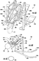
- FIG. 9-11 illustrate exercise apparatus 420, another example implementation of exercise apparatus 20.
- exercise apparatus 420 provides concurrent or synchronized adjustment of both step height and stride length.
- Exercise apparatus 420 comprises frame 424 (partially shown in broken lines), arms426L, 426R (collectively referred to as arms 426), foot links 428L, 428R (collectively referred to as foot links 428), support links 429, footpads 430L, 430R (collectively referred to as foot pads 430), left crank 434L and right crank 434R (collectively referred to as cranks 434), resistance system 436, flexible member guides 438L, 438R (collectively referred to as flexible member guides 438), flexible members 444L, 444R (collectively referred to as flexible members 444), stride length adjusting links 446L, 446R (collectively referred to as links 446), and adjustment synchronizer 450 comprising adjustment member 454, adjuster 458, link support guides 462L, 462R (collectively referred
- Frame 424 supports the remaining components or elements of exercise apparatus 420 upon an underlying terrain or support surface.
- Frame 424 comprises base 474, uprights 475 and front center post 478.
- Base 474 extends along the floor or other underlying supporting surface.
- Uprights 475 extend upwardly from base 474 and pivotably support arms 426. Uprights 475 further pivotably support guides 462.
- Center post 478 extends upwardly from base 424 and supports crank 434, resistance system 436, guides 438, adjustment member 454 and adjuster 458.
- frame 424 may have other configurations.
- Arms 426 comprise structures pivotably supported by uprights 475 for rotation about axis 476.
- Each of arms 426 has a rearward extending portion 482 and a forwardly extending portion 484.
- Rearward extending portion 482 extends rearward from axis 476 and is pivotably coupled to a respective one of foot links 428.
- Forward extending portion 484 extends forward from axis 476 and has an end connected to a respective one of flexible members 444.
- Foot links 428 extend between arms 426 and footpads 430.
- Each of foot links 428 has an upper end pivotally connected to rearward extending portion 482 of the respective arm 426 and a lower end supporting a respective one of footpads 430.
- Each of foot links 428 is further controlled by link 429 which has a first end pivotally secured to the respective one of foot links 428 and a second end pivotally secured to guide 462. Links 429 connect foot links 428 to guide 462 via the pivoting member that holds guide 462.
- each of links 429 is releasably connectable to the associated link 428 at one of plurality of available vertically spaced mounting locations.
- each foot link 428 comprises a forwardly extending plate or year having column of vertically spaced apertures by which the end portion of link 429 may be pinned or otherwise mounted. Selectively repositioning the end of link 429 in one of the various vertically spaced attachment or mounting points on the associated foot links 428 allows a person to adjust the range of stride length such that the minimum or maximum of the stride length would be uniformly larger or smaller.
- each of links 429 may alternatively have a resiliently extendable/compressible length to provide cushioning.
- each of links 429 may comprise a shock-absorber like hydraulic or pneumatic cylinder-piston shock assembly.
- each of links 429 may comprise a resiliently compressible leaf spring, an elastomeric rubber-like link or other elongated member having a resiliently adjustable length.
- Footpads 430 are supported at lower end of foot links 428. Footpads 430 comprise platforms upon which a person exercising places his or her feet during exercise, and against which a person applies force to move foot pads 430 along an elliptical path. Foot pads 430 are linked to one another to move in unison along the same elliptical path (paths of the same shape), wherein the paths taken by foot pads 430 are of the same elliptical shape, but are out of phase with one another. In the example illustrated, foot pads 430 move through elliptical paths of the same shape, but which are 180° out of phase with respect to one another.
- foot pad 430L when foot pad 430L is at the uppermost position along the shape of the elliptical path, foot pad 430R is at the lowermost position along the shape of the elliptical path. Further, when foot pad 430L is at the forward-most position along the shape of the elliptical path, foot pad 430R is at the rearward-most position along the shape of the elliptical path.
- footpads 430 are supported and guided so as to move through parallel elliptical paths within parallel vertical planes wherein each footpads 430 overlaps a longitudinal centerline of exercise apparatus 420 and/or vertically overlaps the other of the footpads at some point during its continuous looping movement (multiple continuous rotations of 360 degrees of cranks 434 about their shared or common axis).
- the paths the footpads 430 are not parallel.
- the paths of footpads 430 have several degrees of convergence at the front of the stride, wherein the footpads still overlap.
- cranks 434 share a common axle and/or rotate about a common central axis 504 (shown in Figure 10 ).
- Left crank 434L comprises an arm 464 (shown in Figure 10 ) which eccentrically and rotationally supports left flexible element crank guide 466L.
- Right crank 434R comprises disk 470 which eccentrically and rotationally supports right flexible element crank guide 466R.
- Crank guides 466 function similarly to crank guides 266. Similar to crank guide 266, left flexible element crank guide 466L and right flexible element crank guide 466R (collectively referred to as crank guides 466) are angularly offset from one another by 180° with respect to axis 504. As a result, footpads 430 move through paths having the same elliptical shape, but wherein the elliptical shaped paths are 180 degrees out of phase with respect to one another.
- Resistance system 436 is similar to resistance system 236 described above. As shown in Figure 9 , resistance system 436 comprises a resistance source 488 which is operably coupled to cranks 434 to resist rotation of cranks 434. In the example illustrated, resistance source 488 is operably coupled to cranks 434 by flexible member 490, stacked pulleys 492, flexible member 494 and resistance source pulley 496. Flexible member 490 wraps about disc 470 of crank 434R and about a first smaller diameter pulley of stacked pulleys 492 which are supported by center post 478. Flexible member 494 wraps about the larger diameter pulley of stacked pulleys 492 and the resistance source pulley 496.
- resistance system 436 utilizes pulleys, such as pulleys 492 and 496
- flexible members 490 and 494 comprise belts.
- pulleys may be replaced with sprockets, wherein flexible members 490 and 494 comprise chains.
- cranks 434 are operably coupled to resistance source 488 by a gear train or other transmission mechanism.
- Resistance source 488 is similar to resistance source 270 described above.
- resistance source 488 comprises a metal plate and one or more magnets forming an Eddy brake.
- the one or more magnets comprise electromagnets, wherein the strength of the magnetic force to be selectively adjusted to control and vary the resistance applied against the rotation of cranks 434.
- resistance source 488 may comprise an electric generator.
- resistance source 488 may comprise two surfaces in frictional contact with one another to apply a frictional resistance against rotation of crank 434.
- air brakes may be utilized.
- other brakes or resistance mechanisms may be utilized.
- Flexible member guides 438 comprise structures or members that guide movement of flexible members 444 between crank guides 466 of cranks 434 and forward extending portions 484 of arms 426.
- guides 438 comprise idler pulleys rotationally supported by center post 478.
- guides 438 may comprise stationary arcuate structures that guide sliding movement of flexible members 444.
- Flexible members 444 comprise elongated flexible or bendable members such as cables, bands, wires, ropes, belts, cords, strings, straps, chains and the like that extend between adjustment member 454 and arms 426.
- Flexible member 444L has a first end portion secured or connected to adjustment member 454 and a second end portion secured or connected to forward extending portion 484 of arm 426L.
- Flexible member 444L has central portions that wrap about a downwardly facing side of flexible member crank guide 466L and a forwardly facing side of guide 438L.
- flexible member 444R has a first end portion secured or connected to adjustment member 454 and a second end portion secured or connected to forward extending portion 484 of arm 426L.
- Flexible member 444R has central portions that wrap about a downwardly facing side of flexible member crank guide 466R and a forwardly facing side of guide 438R.
- Stride length adjusting links 446 comprise elongate rods, bars or linkages having a first end portion 494 pivotably attached to a respective one of crank 434 and a second end portion 496 pivotably attached to a respective one of supports 464 for pivotal movement about an associated transverse axis 498.
- the longitudinal spacing or distance d between axes 476 and 498 of the link 446 defines the stride length of the elliptical path being taken by footpads 430.
- pivot axis of guide 462 at the frame is illustrated as collinear / common with the pivot axes 476 of arms 426, in exercise apparatus 420, the pivot axes of arms 426 do not have to be the same as the pivot axis (at the frame) of guide 462.
- the pivot axis 476 of arms 426 is tangent to a circumference of spool 470.
- Such a configuration reduces or minimizes the extent to which supports 464 (described hereafter) move along guides 462 as footpads 430 traverse their respective paths.
- the pivot axis 476 of arms 426 is offset (non-tangent) with respect to the circumference of spool 470.
- Adjustment synchronizer 450 simultaneously or concurrently adjusts the step height and the stride length of the elliptical path being taken by foot pads 430 in a synchronous manner in response to a single adjustment request.
- adjustment synchronizer 450 comprises adjustment member 454, adjuster 458, link support guides 462L, 462R (collectively referred to as guides 462), link supports 464L, 464R (collectively referred to as supports 464), support biases 467L, 467R (collectively referred to as biases 467), synchronization coupler 468, spool 470, support adjustment flexible members 472L, 472R (collectively referred to as flexible members 472), and monitor 260.
- Adjustment member 454 comprises a structure forming a pair of elongate bars 500, extensions 502L, 502R and cam 503. Bars 500 are connected to one another and are pivotally supported by center post 487 of frame 424 so as to pivot in unison together about axis 504. In the example illustrated, bars 500 rotate about the rotational axis 504 of cranks 434. In other implementations, bars 500 rotate or pivot about an axis different than that of cranks 434.
- Adjuster 458 comprises a mechanism to rotate adjustment member 454 through a range of less than 180° so as to adjust angular positioning of extensions 502 and the end points of flexible members 444 so as to adjust the step height of the elliptical paths being taken by footpads 430.
- adjuster 458 is similar to adjuster 258 described above.
- Adjuster 458 comprises an electrically powered motor 510 that rotationally drives screw or worm screw 512 which passes through a threaded member or nut that is pivotably coupled to bars 500 for pivotal movement about an axis perpendicular to the axis of worm screw 512 but secured against rotation about the axis of worm screw 512. Rotation of worm screw 512 moves an end portion of adjustment member 454 along the axis of worm screw 512 to pivot adjustment member 454 about its axis 504.
- Extensions 502L, 502R project from opposite sides of bars 500 and provide mounting points or connection points for ends or end portions of flexible members 444.
- extensions 502L and 502R extend in opposite directions from opposite sides of bars 500 and are connected to end portions of flexible members 444L and 444R, respectively.
- adjustment member 454 has other shapes and configurations, wherein adjustment member 454 provides laterally spaced mounting points at one end on one side of axis 504 for connecting to ends of flexible members 444.
- Cam 503 comprises a structure which rotates with bars 500 about axis 504 and provides a mounting surface and guide for synchronization coupler 468.
- cam 503 comprises a pie-shaped wedge having an outer curved surface against which synchronization coupler 468 wraps or from which coupler 468 unwraps as a result of rotation of member 454.
- cam 503 is illustrated as radial or arcuate, in other implementations, cam 503 may have other shapes other than a strict radius to allow variation of the ratio of vertical to horizontal rate of change in the stride.
- extension 502L, flexible member 444L and crank guide 466L form a left stride height mechanism, wherein the stride height of the elliptical path taken by foot pad 430L is controlled by the positioning of extension502L which controls the degree to which flexible member 444L wraps about crank guide 466L.
- Extension 502R, flexible member 444R and crank guide 466R form a right stride height mechanism, wherein the stride height of the elliptical path taken by foot pad 430R is controlled by the positioning of extension 502R which controls the degree to which flexible member 444R wraps about crank guide 466R.
- Cranks 434 and stride length adjusting links 446 form a stride length mechanism, wherein the stride length of the elliptical path for each of footpads 430 is controlled by the positioning of the pivot axis 498 of each of links 446 relative to axis 476 of arms 426.
- Link supports 464 movably support the upper ends of links 446 to facilitate controlled repositioning of the pivot axis 498 of such links 446 relative to axis 476.
- link supports 464 are slidably supported along guides 462 for linear sliding movement in fore and aft directions.
- Link supports 464 are resiliently biased in one direction by support biases467.
- support biases 467 comprise gas cylinder-piston assemblies having one end mounted or secured to link support guides 462 and an opposite end secured to the respective one of supports 464.
- support biases 467 resiliently bias supports 464 in a forward direction.
- support biases 467 may comprise other biasing mechanisms such as compression springs or other types of springs depending upon the mounting arrangement.
- Synchronization coupler 468, spool 470, and support adjustment flexible members 472L, 472R cooperate to mechanically link the rotational adjustment of adjustment member 454 which adjusts step height to the movement of supports 464 and pivot axis 498 of links 446.
- synchronization coupler 468 comprises a flexible member such as a strap, web, cord, cable, band or belt having a first end portion fixed or secured to cam 503 of adjustment member 454 and a second opposite end portion fixed or secured to spool 470.
- Spool 470 comprises a cylindrical member rotatably supported by frame 424 for rotation about an axis.
- spool 470 rotates about axis 480, the pivot axis of arms 426.
- spool 470 rotates about a different axis.
- coupler 468 wraps about or unwraps from the spool 470 while flexible members 472 unwraps from or wrap about a 470, respectively.
- Flexible members 472 comprise a strap, web, cord, rope, cable, band or belt having a first end portion fixed or secured to spool 470 and a second opposite end portion fixed or secured to a respective one of supports 464.
- flexible members 472 are secured to spool 470 so as to wind about spool 470 in a first rotational direction while coupler 468 is secured to spool 470 so as to wind about spool 470 in a second opposite rotational direction.
- coupler 468 is being wound about spool 470
- flexible members 466 are being unwound from spool 470, and vice versa.
- controller 292 In operation, in response to signals generated by controller 292 as a result of either receiving a command or selection through input 290 or being directed by an exercise program stored in a non-transitory memory associate with controller 292, controller 292 generates control signals causing motor 510 to rotate screw 512 to rotate adjustment member 454 about axis 504 which adjusts the positioning of the endpoints of flexible members 444. This repositioning of the endpoints of flexible members 444 changes the degree to which flexible members 444 wrap about crank guides 466 and adjusts the step height of the elliptical path being taken by footpads 430. Rotation of adjustment member 454 by adjuster 458 causes end portions of coupler 468 to wind or unwind relative to cam 503 and to rotate spool 470.
- Rotation of spool 470 winds or unwinds flexible members 472 so as to either move supports 464 and pivot axis 498 rearwardly against the bias of biases 467 or to allow the bias of biases 467 to move supports 464 and pivot axis 498 forwardly. Movement of pivot axis 498 relative to the rotational axis 476 of arms 426 adjusts the stride length of the elliptical path being taken by footpads 430.
- coupler 468 in the form of a flexible member, spool 470 and flexible members 472 which move sliding supports 464 against the bias
- coupler 468 may comprise a gear train, mechanical link pivot connections or other force transmitting members.
- the locations at which links 446 are pivotably coupled to arms 426 may alternatively be achieved by pivoting the location of the pivot axis 498 or by moving the location of the pivot axis 498 along a rack and pinion arrangement.
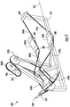
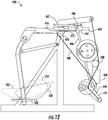
- Figures 12-15 illustrate adjustment member 454 and supports 464 in a first state during which supports 464 and the associated pivot axis 498 of links 446 are at an intermediate position along guide 462 and movement of one of footpads 430 along an elliptical path corresponding to the step height and stride length dictated by the positioning of adjustment member 454 and supports 464.
- Figure 16 illustrates adjustment member 454 and supports 464 in a second example state after being synchronously or concurrently repositioned, from one position to one another by adjuster 458.
- adjustment member 454 has been rotated clockwise and downward to change the degree to which flexible member 444 wraps against and about crank guide 466 so as to (reduce) adjust the step height of the elliptical path that footpads 430 move along.
- Rotation of adjustment member 454 further results in rotation of cam 503 which pulls coupler 468 to rotate spool 470 so as to wind flexible member 472 and move supports 464 and the associated pivot axis 498 rearwardly along guide 462 against the bias of bias 467.
- the stride length of elliptical path taken by foot pads 430 is concurrently changed (increased). Consequently, the shape of the elliptical path taken by footpads 430 changes from the elliptical path 520 shown in Figures 13-15 to the elliptical path 522 shown in Figure 16 (and shown in broken lines in Figure 12 ).
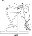
- Figure 17 illustrates adjustment member 454 and supports 464 in a third example state after being synchronously or concurrently repositioned, from one position to one another by adjuster 458.
- adjustment member 454 has been rotated counterclockwise from the position shown in Figure 13 and downward to change the degree to which flexible member 444 wraps against and about crank guide 466R so as to adjust(increase) the step height of elliptical path that footpads 430 move along.
- Rotation of adjustment member 454 further results in rotation of cam 503 which unwinds coupler 468 which unwinds flexible member 472 in response to force is applied by biases 467 and moves support 464 and the associated pivot axis 498 forwardly along guide 462.
- adjuster 458 in response to control signals from controller 292, may selectively reposition adjustment member 454 at a multitude of different angular positions between the example extreme shown in Figures 16 and 17 which would also result in pivot axis 498 being selectively repositioned any corresponding multitude of different positions along guide 462 between the example extreme positions shown in Figure 16 and 17 .
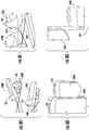
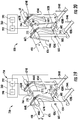
- FIG 18 illustrates exercise apparatus 620, another example implementation of exercise apparatus 20.
- Exercise apparatus 620 is similar to exercise apparatus 420 except that exercise apparatus 620 adjusts the step height in a fashion similar to the adjustment of the step height in exercise apparatus 220 and comprises adjustment synchronizer 650 in place of adjustment synchronizer 450.
- Synchronizer 650 comprises supports 664L, 664R (collectively referred to as supports 664), gear 666, toothed belt 668, driveshaft 670 comprising gear 672 and pinion gears 674L, 674R (collectively referred to as pinion gear 674).
- Supports 664 pivotably support end portions of links 446 for pivotal movement about pivot axis 498.
- Each of supports 664 is pivotally supported by a respective one of arms 426 about axes 665L and 665R.
- Each of supports 664 further comprises a rack gear 667L, 667R having teeth in meshing engagement with the teeth of a respective one of pinion gears 674.
- Gear 666 comprises a gear coupled to adjustment member 454 so as to rotate in response to pivoting of adjustment member 454.
- gear 666 is fixed or joined to adjustment member 454 to rotate with the rotation of adjustment member 454 at a 1:1 ratio.
- gear 666 is operably coupled to adjustment member 454 by a gear train or other transmission so as to rotate with the rotation of adjustment member 454 at a predetermined ratio greater than or less than 1:1.
- Toothed belt 668 wraps about gear 666 and gear 672 with its teeth intermeshed with the teeth of gear 666 and gear 672.
- Belt 668 transmits torque from gear 666 to driveshaft 670.
- torque or rotation may be transmitted from adjustment member 454 and driveshaft 670 by other transmission such as a chain and sprocket arrangement, a gear train or a belt and pulley arrangement.
- Drive shaft 670 comprises a shaft rotatably supported by frame 424 independent of the rotation of arms 426 about axis 476.
- driveshaft 670 is also rotatably supported about axis 476.
- Driveshaft 670 carries gear 672 and pinions 674.
- Pinions 674L, 674R have teeth intermeshing with rack gears 667L, 667R, respectively.
- controller 292 In operation, in response to signals generated by controller 292 as a result of either receiving a command or selection through input 290 or being directed by an exercise program stored in a non-transitory memory associate with controller 292, controller 292 generates control signals causing motor 510 to rotate screw 512 to rotate adjustment member 454 about axis 680 which adjusts the positioning of the endpoints of flexible members 244. This repositioning of the endpoints of flexible members 244 changes the degree to which flexible members 244 wrap about crank guides 266 and adjusts the step height of the elliptical path being taken by footpads 430. Rotation of adjustment member 454 by adjuster 458 causes gear 666 to also rotate.
- Rotation of gear 666 drives rotation of driveshaft 670 via a toothed belt 668 and gear 672.
- Rotation of driveshaft 670 drives rack gears 667 to pivot supports 664 about axes 665 to move pivot axis 498 relative to axis 476 of arms 426.
- rotation of adjustment member 454 adjusts the step height of the elliptical path taken by footpads 430 and concurrently or synchronously adjusts the position of axes 498 so as to also adjust the stride length of the elliptical path taken by footpads 430.
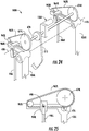
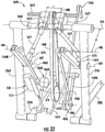
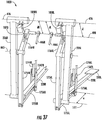
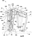
- FIG 19 illustrates exercise apparatus 720, another example implementation of exercise apparatus 20.
- Exercise apparatus 720 is similar to exercise apparatus 620 except that exercise apparatus 720 comprises adjustment synchronizer 750 in place of adjustment synchronizer 650.
- Those remaining components of exercise apparatus 720 are shown in Figure 19 and numbered similarly as exercise apparatus 620 or are shown in Figure 18 .
- exercise apparatus 720 comprises frame 424, foot links 428, footpads 430L, 430R (collectively referred to as foot pads 430), crank 434, resistance system 436, and flexible member guides 438L, 438R (collectively referred to as flexible member guides 438).
- Adjustment synchronizer 750 comprises adjustment member 454, supports 664L, 664R (collectively referred to as supports 664), driveshaft 770 comprising pinion gears 674L, 674R (collectively referred to as pinion gear 674), electric powered motor 766 and monitor 260. Adjustment member 454 and supports 664 are described above. Driveshaft 770 is similar to driveshaft 670 except that driveshaft 770 omits gear 672 as it is directly driven by motor 766.
- Motor 766 in response to control signals from controller 292 drives driveshaft 770 to drive pinion 674 which rotate against rack gears 667 to pivot supports 664 about axis 665 which moves pivot axis 498 of links 446 relative to axis 476 of arms 426 so as to adjust the stride length of the elliptical path taken by footpads 430 (shown in Figure 18 ).
- controller 292 In operation, in response to signals generated by controller 292 as a result of either receiving a command or selection through input 290 or being directed by an exercise program stored in a non-transitory memory associated with controller 292, controller 292 generates control signals causing motor 510 to rotate screw 512 to rotate adjustment member 454 about axis 680 which adjusts the positioning of the endpoints of flexible members 244. This repositioning of the endpoints of flexible members 244 changes the degree to which flexible members 244 wrap about crank guides 266 and adjusts the step height of the elliptical path being taken by footpads 430.
- motor 766 in response to control signals from controller 292, drives driveshaft 770 to drive pinion 674 which rotate against rack gears 667 to pivot supports 664 about axis 665 which moves pivot axis 498 of links 446 relative to axis 476 of arms 426 so as to adjust the distance d separating axes 476 and 498 and so as to adjust the stride length of the elliptical path taken by footpads 430 (shown in Figure 18 ).
- rotation of adjustment member 454 to adjust the step height of the elliptical path taken by footpads 430 concurrently or synchronously adjusts the position of axes 498 so as to also adjust the stride length of the elliptical path taken by footpads 430.
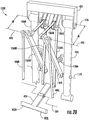
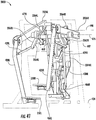
- FIG 20 illustrates exercise apparatus 820, another example implementation of exercise apparatus 20.
- Exercise apparatus 820 is similar to exercise apparatus 720 except that apparatus 720 replaces the lift actuator provided by motor 510 and screw 512 with flexible member 810 and return spring 812.
- Those remaining components of exercise apparatus to relate 20 are numbered similarly in Figure 21 and/or are shown in the above figures.
- Flexible member 810 has a first end attached to a side of adjust member 545 on an opposite side of axis 680 as extensions 502L and 502R which are attached to flexible members 244.
- Flexible member 810 has a second end secured to driveshaft 770 which serves as a spool about which flexible member 810 winds and unwinds in response to being rotationally driven by motor 766.
- Spring 812 comprises a tension spring having one end mounted to adjust member 545 on an opposite side of axis 680 as flexible member 810 and has a second end secured to frame 424. Spring 812 applies a bias force to resolve a bias adjustment member 545 about axis 680.
- controller 292 In operation, in response to signals generated by controller 292 as a result of either receiving a command or selection through input 290 or being directed by an exercise program stored in a non-transitory memory associated with controller 292, controller 292 generates control signals causing motor 766 to rotate driveshaft 770. Rotation of driveshaft 770 winds or unwinds flexible member 810 to pivot adjust member 545 about axis 680 to reposition extensions 502 and the endpoints of flexible members 244 so as adjust the degree to which flexible members 244 wrap about crank guides 266 and so as to adjust the step height of the elliptical path being taken by footpads 430.
- rotation of driveshaft 770 drives pinions 674 which rotate against rack gears 667 to pivot supports 664 about axis 665 which moves pivot axis 498 of links 446 relative to axis 476 of arms 426 so as to adjust the distance d separating axes 476 and 498 and so as to adjust the stride length of the elliptical path taken by footpads 430 (shown in Figure 18 ).
- rotation of adjustment member 454 adjusts the step height of the elliptical path taken by footpads 430 and concurrently or synchronously adjusts the position of axes 498 so as to also adjust the stride length of the elliptical path taken by footpads 430.
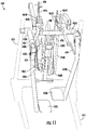
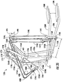
- FIG 21-23 illustrates exercise apparatus 920, another example implementation of exercise apparatus 20.
- Exercise apparatus to 920 this similar to exercise apparatus 620 described above except that exercise apparatus 920 utilizes an alternative mechanism for adjusting the positioning of pivot axis 498 of the upper end of links 446 relative to axis 476 of arms 426.
- Those remaining components of exercise apparatus 920 that correspond to components of exercise apparatus 620 are numbered similarly or are shown in Figure 19 .
- exercise apparatus 920 comprises frame 424, footpads 430L, 430R (collectively referred to as foot pads 430), crank 434, resistance system 436, and flexible member guides 438L, 438R (collectively referred to as flexible member guides 438).
- the arrangement shown Figure 22 is provided as part of exercise apparatus 420 as an alternative for adjusting the position of pivot axis 498 relative to axis 476.
- exercise apparatus 920 comprises adjustment synchronizer 950 which adjusts, in a coordinated or synchronized manner, the step height and stride length of the elliptical path being taken by footpads 430.
- Synchronizer 950 comprises adjustment member 454, adjuster 458, monitor 260, gear 666, tooth belt 668 and driveshaft 670, each of which are described above with respect to Figure 19 .
- Synchronizer 950 further comprises slide rails 962L, 962R (collectively referred to as slide rails 962), link supports 964L, 964R, pinion gears 963L, 963R (collectively referred to as gears 963) and tooth belts 967L, 967R (collectively referred to as belts 967).
- Slide rails 962 comprise rods, tubes, beams or other structures fixed to arms 426. Slide rails 962 extend forwardly of axis 476 and guide movement of link supports 964 in fore and aft directions. Slide rails 962 rotationally support pinion gears 963 at their outer foremost ends. Pinion gears 963 cooperate with pinion gears 674 to support a respective one of toothed belts 674.
- Link supports 964 pivotally support the upper end of links 446 for pivotal movement about a respective axis 498.
- the upper end each of links 446 provided with a clevis 969 that pivotably secures the upper end of each of links 446 to support 964.
- each of support 964 is clamped to the associated toothed belt 967 so as to move back and forth with the movement of the respective belt 967.
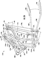
- controller 292 In operation, in response to signals generated by controller 292 as a result of either receiving a command or selection through input 290 or being directed by an exercise program stored in a non-transitory memory associated with controller 292, controller 292 generates control signals causing motor 510 to rotate screw 512 (shown in Figure 18 ) to rotate adjustment member 454 about axis 680 which adjusts the positioning of the endpoints of flexible members 244. This repositioning of the endpoints of flexible members 244 changes the degree to which flexible members 244 wrap about crank guides 266 and adjusts the step height of the elliptical path being taken by footpads 430. Rotation of adjustment member 454 by adjuster 458 causes gear 666 to also rotate.
- Rotation of gear 666 drives rotation of driveshaft 670 via a toothed belt 668 and gear 672.
- Rotation of driveshaft 670 drives rack gears pinion gears 674 which drive toothed belts 967. Movement of toothed belts 967 linearly translates supports 964 along slide rails 962 to reposition the pivot axes 498 of the upper ends of links 446 relative to pivot axis 476 of arms 426.
- rotation of adjustment member 454 adjusts the step height of the elliptical path taken by footpads 430 and concurrently or synchronously adjusts the position of axes 498 so as to also adjust the stride length of the elliptical path taken by footpads 430.
- Figure 23 illustrates pivoting of arm 426L and slide rail line 962L, link support 964L, pinion gear 963L and toothed belt 967L about axis 476 during reciprocation of arm 426L.
- reciprocation of arm 426L results in slight movement of link support 964L through a stroke of arm 426L.
- the connection of link support 964L to either the top or the bottom of tooth belt 967L determines which end of the path will have a slight acceleration.
- Exercise apparatus 1020 is similar to exercise apparatus 920 except that exercise apparatus 1020 drives driveshaft 670 with a motor 1068 instead of utilizing gear 666, belt 668 and gear 672. Similar to exercise apparatus 920, exercise apparatus 1020 omits adjuster 458 and instead utilizes flexible member 810 and spring 812 (shown in Figure 21 ) to actuate or pivot adjustment member 545.
- the illustrated pinion gears 674, 963 and toothed belts 967 alternatively comprise belt and pulley arrangement or chain sprocket arrangements.
- FIG 26 illustrates exercise apparatus 1120, another example implementation of exercise apparatus 20.
- Exercise apparatus 1120 is similar to exercise apparatus 1520 described hereafter. Many of the components or elements of exercise apparatus 1120 correspond to components previously described above with respect to exercise apparatus 420.
- Exercise apparatus 1120 comprises link supports 1164L, 1164R, flexible member guides 1165, biases 1166L, 1166R (collectively referred to as biases 1166), and stride length adjusting flexible members 1168L, 1168R (collectively referred to as flexible members 1168).
- Those components of exercise apparatus 1120 which correspond to components of exercise apparatus 420 are numbered similarly in Figure 26 or are shown in Figures 9-11 .
- Link supports 1164 pivotably support link supports 446 (described above) for pivotal movement about axes 498 each link support 1164 is itself pivotally supported by a respective one of arms 426 about a respective axis 1170. Pivoting of link supports 1164 about axis 1170 repositions the respective axis 498 relative to axis 476 of arms 426 to adjust the distance d (dR the right side and dL for the left side) between the respective axes 498 and axis 476 to adjust a stride length of the elliptical paths taken by the associated footpads 430. The distances dR and dL are equally and simultaneously adjusted through movement of flexible members 1165.
- Flexible member guides 1165 comprise pulleys that guide and direct movement of flexible members 1168.
- Biases 1166 comprise mechanisms that resiliently biases link supports 1164 in one direction about axis 1170.
- biases 1166 comprise gas cylinders that resiliently bias and urge link supports 1164 in a forward direction.
- biases 1166 comprise compression springs.
- biases 1166 comprise other spring arrangements.
- a torsion spring may be coupled between a respective one of link supports 1164 and a respective one of arms 426.
- Flexible members 1168 comprise cords, cables, straps, belts, ropes or other flexible members. Flexible members 1168 operably couple adjustment member 454 and link supports 1164. Flexible members 1168 extend from adjustment member 454, through guides 1165 and into connection with link supports 1164. In the example illustrated, adjustment member 454 is connected to flexible members 444 on a first side of axis 504 and is pivotally connected to flexible members 1168 on a second side of axis 504.
- controller 292 In operation, in response to signals generated by controller 292 as a result of either receiving a command or selection through input 290 or being directed by an exercise program stored in a non-transitory memory associated with controller 292, controller 292 generates control signals causing motor 510 to rotate screw 512 (shown in Figure 18 ) to rotate adjustment member 454 about axis 504 which adjusts the positioning of the endpoints of flexible members 444.
- controller 292 In operation, in response to signals generated by controller 292 as a result of either receiving a command or selection through input 290 or being directed by an exercise program stored in a non-transitory memory associated with controller 292, controller 292 generates control signals causing motor 510 to rotate screw 512 (shown in Figure 18 ) to rotate adjustment member 454 about axis 504 which adjusts the positioning of the endpoints of flexible members 444.
- This repositioning of the endpoints of flexible members 244 changes the degree to which flexible members 444 wrap about crank guides 466 and adjusts the step height of the
- Rotation of adjustment member 454 by adjuster 458 also moves the endpoints of flexible members 1168 which results in link supports 1164 either being pivoted against the bias of biases 1166 about axis 1170 or pivoted under the influence of biases 1166 about axis 1170.
- each of the axes 498 at the end of link supports 1164 is pivoted and moved relative to axis 476 of arms 262 to adjust a stride length of the elliptical path being taken by footpads 430.
- rotation of adjustment member 454 to adjust the step height of the elliptical path taken by footpads 430 concurrently or synchronously adjusts the position of axes 498 so as to also adjust the stride length of the elliptical path taken by footpads 430.
- FIG 27 illustrates exercise apparatus 1220, another example implementation of exercise apparatus 20.
- Exercise apparatus 1220 is similar to exercise apparatus 1120 except that exercise apparatus 1220 comprises support link guides 462, link supports 464 and biases 466 (described above with respect to exercise apparatus 420).
- Those remaining components of exercise apparatus 1220 which correspond to components of exercise apparatus 1120 and/or 420 are numbered similarly and are shown in Figures 9-11 and 26 .
- controller 292 In operation, in response to signals generated by controller 292 as a result of either receiving a command or selection through input 290 or being directed by an exercise program stored in a non-transitory memory associated with controller 292, controller 292 generates control signals causing motor 510 to rotate screw 512 to rotate adjustment member 454 about axis 504 which adjusts the positioning of the endpoints of flexible members 444. This repositioning of the endpoints of flexible members 444 changes the degree to which flexible members 444 wrap about crank guides 466 and adjusts the step height of the elliptical path being taken by footpads 430.
- Rotation of adjustment member 454 by adjuster 458 also moves the endpoints of flexible members 1168 which results in link supports 464 either being slid along the axes of guides 462 against the force of biases 1166 or under the influence of biases 1166.
- each of the axes 498 at the end of link supports 464 is linearly translated and moved relative to axis 476 of arms 262 to adjust a stride length of the elliptical path being taken by footpads 430.
- rotation of adjustment member 454 adjusts the step height of the elliptical path taken by footpads 430 and concurrently or synchronously adjusts the position of axes 498 so as to also adjust the stride length of the elliptical path taken by footpads 430.
- FIG 28 illustrates exercise apparatus 1320, another example implementation of exercise apparatus 20.
- Exercise apparatus 1320 is similar to exercise apparatus 1120 except that exercise apparatus 1320 comprises flexible member guides 1365, biases 1366 and flexible members 1368 in place of guides 1165, biases 1166 and flexible members 1168.
- Those remaining components of exercise apparatus 1320 which correspond to components of exercise apparatus 1120 and/or 420 are numbered similarly and are shown in Figures 9-11 and 26 .
- Flexible member guides 1365 comprise pulleys supported by frame 424 so as to guide movement of flexible members 1368.
- Flexible members 1368L, 1368R extend through and are guided by guides 1365.
- the perimeter / circumference of guides 1365 are tangent to the pivot axis 476.
- Such a configuration reduces or minimizes the extent to which supports 464 (described hereafter) move along guides 462 as the footpads traverse their respective paths.
- the pivot axis 476 of arms 426 is offset (non-tangent) with respect to the circumference of guides 1365.
- Flexible members 1368 each have a first portion connected to adjustment member 454 on an opposite side of axes 504 as extensions 502 and a second end portion connected to a respective one of link supports 1164.
- Biases 1366 resiliently bias link supports 1164 in one direction about axis 1170.
- biases 1366 comprise compression springs.
- biases 1366 comprise other biasing mechanism such gas cylinders, torsion springs, tension springs and the like operably coupled between a respective one of arms 426 and the link support 1164.
- controller 292 In operation, in response to signals generated by controller 292 as a result of either receiving a command or selection through input 290 or being directed by an exercise program stored in a non-transitory memory associate with controller 292, controller 292 generates control signals causing motor 510 to rotate screw 512 (shown in Figure 9 ) to rotate adjustment member 454 about axis 504 which adjusts the positioning of the endpoints of flexible members 444.
- controller 292 In operation, in response to signals generated by controller 292 as a result of either receiving a command or selection through input 290 or being directed by an exercise program stored in a non-transitory memory associate with controller 292, controller 292 generates control signals causing motor 510 to rotate screw 512 (shown in Figure 9 ) to rotate adjustment member 454 about axis 504 which adjusts the positioning of the endpoints of flexible members 444.
- This repositioning of the endpoints of flexible members 444 changes the degree to which flexible members 444 wrap about crank guides 466 and adjusts the step height of the
- Rotation of adjustment member 454 by adjuster 458 also moves the endpoints of flexible members 1368 which results in link supports 1164 being pivoted about axis 1170 against the force of biases 1366 or under the influence of biases 1366.
- each of the axes 498 at the end of link supports 1164 is moved relative to axis 476 of arms 262 to adjust a stride length of the elliptical path being taken by footpads 430.
- rotation of adjustment member 454 to adjust the step height of the elliptical path taken by footpads 430 concurrently or synchronously adjusts the position of axes 498 so as to also adjust the stride length of the elliptical path taken by footpads 430.
- FIGS 29 and 30 illustrate exercise apparatus 1420, another example implementation of exercise apparatus 20.
- Exercise apparatus 1420 is similar to exercise apparatus 1320 except that exercise apparatus 1420 comprises link support guides 462 and link supports 464 (described above with respect to exercise apparatus 420) in place of link supports 1368.
- Those remaining components of exercise apparatus 1420 which correspond to components of exercise apparatus 1320 and exercise apparatus 420 are numbered similarly and/or are illustrated above and Figures 9-11 and 26 .
- controller 292 In operation, in response to signals generated by controller 292 as a result of either receiving a command or selection through input 290 or being directed by an exercise program stored in a non-transitory memory associated with controller 292, controller 292 generates control signals causing motor 510 to rotate screw 512 (shown in Figure 9 ) to rotate adjustment member 454 about axis 504 which adjusts the positioning of the endpoints of flexible members 444.
- controller 292 In operation, in response to signals generated by controller 292 as a result of either receiving a command or selection through input 290 or being directed by an exercise program stored in a non-transitory memory associated with controller 292, controller 292 generates control signals causing motor 510 to rotate screw 512 (shown in Figure 9 ) to rotate adjustment member 454 about axis 504 which adjusts the positioning of the endpoints of flexible members 444.
- This repositioning of the endpoints of flexible members 444 changes the degree to which flexible members 444 wrap about crank guides 466 and adjusts the step height of the
- Rotation of adjustment member 454 by adjuster 458 also moves the endpoints of flexible members 1368 which results in link supports 464 either being slid along the axes of guides 462 against the force of biases 466 or under the influence of biases 466.
- each of the axes 498 at the end of link supports 464 is linearly translated and moved relative to axis 476 of arms 426 to adjust a stride length of the elliptical path being taken by footpads 430.
- rotation of adjustment member 454 to adjust the step height of the elliptical path taken by footpads 430 concurrently or synchronously adjusts the position of axes 498 so as to also adjust the stride length of the elliptical path taken by footpads 430.
- FIGS 31 and 32 illustrate exercise apparatus 1520, another example implementation of exercise apparatus 20.
- Exercise apparatus 1520 is similar to exercise apparatus 220, exercise apparatus 420 and exercise apparatus 1320, incorporating a combination of the horizontal stride length adjustment mechanism of exercise apparatus 420 and 1320 and the vertical step height adjustment mechanism of exercise apparatus 220.
- exercise apparatus 1520 provides concurrent or synchronized adjustment of both step height and stride length.
- Exercise apparatus 1520 comprises frame 424 (partially shown in broken lines), legs 226, foot links 228, footpads 230, left crank 434L and right crank 434R (collectively referred to as cranks 434), resistance system 436, flexible member guides 438L, 438R (collectively referred to as flexible member guides 438), flexible members 1544L, 1544R (collectively referred to as flexible members 1544), flexible member guides 1546L, 1546R (collectively referred to as flexible member guides 1546), flexible element guides 1547L, 1547R (collectively referred to as flexible element guides 1547), stride length adjusting links 1164, , biases 1366, adjustment member 454, adjuster 458, synchronization coupler 468, spool 470, and support adjustment flexible members 472.
- Flexible members 1544 are similar to flexible members 244 except that flexible members 1544 extend from their respective extensions 502 of adjustment member 454, about their respective crank guides 466, their respective flexible element guides 438, about their respective flexible element guides 1546, about their respective flexible element guides 1547 to securement point 1549 of frame 424.
- extension 502L, flexible member 1544L and crank guide 466L form a left stride height mechanism, wherein the stride height of the elliptical path taken by foot pad 230L is controlled by the positioning of extension 502L which controls the degree to which flexible member 1544L wraps about crank guide 466L.
- Extension 502R, flexible member 444R and crank guide 466R form a right stride height mechanism, wherein the stride height of the elliptical path taken by foot pad 230R is controlled by the positioning of extension 502R which controls the degree to which flexible member 1544R wraps about crank guide 466R.
- Link supports 1164 and stride length adjusting links 446 form a stride length mechanism, wherein the stride length of the elliptical path taken each of footpads 230 is controlled by the positioning of the pivot axis 498 of each of links 446 relative to axis 476 of arms 426.
- controller 292 In operation, in response to signals generated by controller 292 as a result of either receiving a command or selection through input 290 or being directed by an exercise program stored in a non-transitory memory associated with controller 292, controller 292 generates control signals causing motor 510 to rotate screw 512 to rotate adjustment member 454 about axis 504 which adjusts the positioning of the endpoints of flexible members 1544. This repositioning of the endpoints of flexible members 1544 changes the degree to which flexible members 1544 wrap about crank guides 466 and adjusts the step height of the elliptical path being taken by footpads 230. Rotation of adjustment member 454 by adjuster 458 causes end portions of coupler 468 to wind or unwind relative to cam 503 and to rotate spool 470.
- Rotation of spool 470 winds or unwinds flexible members 472 so as to either pivot supports 1164 about pivot axis 498 rearwardly against the bias of biases 1366 or to allow the bias of biases 1366 to pivot supports 1164 and pivot axis 498 forwardly. Movement of pivot axis 498 relative to the rotational axis 476 of arms 426 adjusts the stride length of the elliptical path being taken by footpads 230.
- coupler 468 in the form of a flexible member, spool 470 and flexible members 472 which pivot supports 1164 against the bias, in other implementations, coupler 468 may comprise a gear train, mechanical link, pivot connections or other force transmitting members.
- FIGs 33 and 34 illustrate exercise apparatus 1620, another example implementation of exercise apparatus 20.
- exercise apparatus 1620 provides concurrent or synchronized adjustment of both step height and stride length.
- Exercise apparatus 1620 comprises frame 424 (shown in Figure 31 ), legs 226, foot links 228, footpads 230 (shown in Figure 31 ), left crank 434L and right crank 434R (collectively referred to as cranks 434), resistance system 436 (shown in Figure 31 ), stride length adjusting links 1164, adjustment member 1654, adjuster 458, synchronization coupler 1668, worm drive 1670, worm drive trolleys 1672, coupling links 1674 and levers 1676.
- Those components which are the same as our which are functionally similar to previously described components are numbered similarly.
- Adjustment member 1654 comprises a two-sided lever which, in the example illustrated, pivots about axis 274 of cranks 434.
- a first side of lever 1654 is pivotally connected to adjuster 458 while a second opposite side of lever 1654, on an opposite side of axis 274, is pivotally connected to a corresponding flexible element 1644.
- Flexible element 1644 extends from adjustment member 1654, wraps partially about a corresponding crank guide 466 and about a corresponding guide 1546 prior to being connected to a corresponding one of foot links 228.
- Adjustment member 1654 further comprises a toothed gear 1678 which rotates in unison with rotation of lever 1654 about axis 274.
- Synchronization coupler 1668 comprises a looped belt wrapping about toothed gear 1678 and about worm drive 1670.
- coupler 1668 comprises a toothed belt meshed with the teeth of toothed gear 1678 intermeshed with teeth of pinion gear 1680 of worm drive 1670.
- Worm drive 1670 comprises a helically threaded shaft having a central pinion gear 1680.
- the helical threads of worm drive 1670 engage corresponding helical threads of worm drive trolleys 1672 which are guided by and slide along shaft 1684.
- Links 1674 comprise rods or bars pivotably coupled to a corresponding one of trolleys 1672 and a second and pivotably secured to lever 1676 through a universal joint.
- Levers 1676 extend from supports 1164 and serve as a lever arm for pivoting supports 1164 about their respective axes 665 to reposition the respective pivot axes 498 relative to axis 476.
- controller 292 In operation, in response to signals generated by controller 292 (shown in Figure 4 ) as a result of either receiving a command or selection through input 290 or being directed by an exercise program stored in a non-transitory memory associated with controller 292, controller 292 generates control signals causing motor 510 to rotate screw 512 to rotate adjustment member 1654 about axis 274 which adjusts the positioning of the endpoints of flexible members 1644. This repositioning of the endpoints of flexible members 1644 changes the degree to which flexible members 1644 wrap about crank guides 466 and adjusts the step height of the elliptical path being taken by footpads 230. Rotation of adjustment member 1654 by adjuster 458 also rotates gear 1678 to drive coupler 1668 to rotate worm drive 1670.
- Rotation of worm drive 1670 moves trolleys 1672 inwards or outwards.
- Figure 33 illustrates trolleys 1672 at an inner most position while
- Figure 34 illustrates trolleys 1672 at an outermost position.
- inward or outward movement of trolleys 1672 causes links 1674 to interact upon lever 1676 so as to pivot supports 1164 about axes 665 as to reposition the pivot axes 498 of stride length adjusting links 446.
- rotation of adjustment member 1654 to adjust the step height of the elliptical path taken by footpads 230 concurrently or synchronously adjusts the position of axes 498 so as to also adjust the stride length of the elliptical path taken by footpads 230.
- FIG 35 and 36 illustrate exercise apparatus 1720, another example implementation of exercise apparatus 20.
- exercise apparatus 1720 provides concurrent or synchronized adjustment of both step height and stride length.
- Exercise apparatus 1720 comprises frame 424 (shown in Figure 31 ), legs 1726, foot links 228, footpads 230, left crank 1734L and right crank 1734R (collectively referred to as cranks 1734), resistance system 436 (shown in Figure 31 ), stride length adjusting links 446, supports 1164, adjustment member 1754, links 1755L, 1755R (collectively referred to as links 1755), foot link support 1756, adjuster 1758, worm drive 1770, worm drive trolleys 1772, coupling links 1774 and levers 1776.
- Those components which are the same as our which are functionally similar to previously described components are numbered similarly.
- cranks 1734 are supported by frame 224 for rotation about axis 270.
- Each of cranks 1734 comprises an arm 1764 having a first end rotating about axis 270 and a second end pivotably connected to a corresponding one of stride length adjusting links 446. Arms 1764 are offset from one another by 180° about axis 270.
- Supports 1164, adjustment member 1754 and lever 1776 are provided by a three legged member rotationally coupled to a corresponding one of legs 1726 so as to rotate or pivot about a corresponding axis 665.
- Supports 1164 extend from axis 665 at one end and are pivotally coupled to a corresponding one of links 446 for rotation about a corresponding axis 498.
- Adjustment members 1754 extend from axis 665 at one and are pivotably connected to a corresponding one of links 1755.
- Each of links 1755 extends from its corresponding adjustment member 1754 to foot link support 1756.
- Foot link supports 1756 a corresponding one of foot links 228.
- each of foot link support 1756 comprises a roller rotationally supported by link 1755 and having a circumferential groove which receives an underside of a corresponding foot link 228 so as to roll along an underside of the corresponding foot link 228.
- Levers 1776 extend from axis 665 at one end and are pivotally connected to a corresponding one of coupling links 1774 at the other end.
- Worm drive 1770 comprises a helically threaded shaft rotatably supported by frame 224 for being selectively rotated by adjuster 1758.
- the helical threads of worm drive 1770 engage corresponding helical threads of worm drive trolleys 1772.
- Links 1774 comprise rods or bars pivotably coupled to a corresponding one of trolleys 1772 and a second end pivotably secured to one of levers 1776 through a universal joint.
- Levers 1776 extend from supports 1164 and serve as a lever arm for pivoting supports 1164 as well as adjustment member 1754 about their respective axes 665 to reposition the respective pivot axes 498 relative to axis 476 (to adjust the stride length of footpads 230) and to reposition supports 1756 relative to the forward pivot axis 1771 joining each foot link 228 to its respective leg 1726 (to adjust the step height of footpads 230).
- Actuator 1758 comprises a motor operably coupled to worm drive 1770 and selectively rotates worm drive 1770.
- actuator 1758 comprises a motor operably coupled to worm drive 1775 by a gear train arrangement 1773.
- actuator 1758 comprises a motor operably coupled to worm drive 1775 by a chain and sprocket arrangement, a toothed belt and pinion gear arrangement or a belt and pulley.
- controller 292 In operation, in response to signals generated by controller 292 (shown in Figure 4 ) as a result of either receiving a command or selection through input 290 or being directed by an exercise program stored in a non-transitory memory associated with controller 292, controller 292 generates control signals causing actuator 1758 to rotate worm drive 1770 so as to move links 1774 inward or outward along axis 476.
- Figure 35 illustrates trolleys 1772 and the ends of links 1774 at outermost positions along axis 476 while Figure 36 illustrates trolleys 1772 and the ends of links 1774 at innermost adjacent positions along axis 476.
- inward or outward movement of trolleys 1772 causes links 1774 to interact upon levers 1776 so as to pivot supports 1164 about axes 665 so as to reposition the pivot axes 498 of stride length adjusting links 446 to adjust the distance d so as to adjust stride length of the continuous elliptical path of footpads 230.
- pivoting a rotation of supports 1164 about the respective axes 665 also moves foot link supports 1756 relative to the respective axis 1771 to concurrently adjust the distance e so as to adjust the step height of the continuous elliptical path of footpads 230.
- FIG 37 illustrates an exercise apparatus 1820, another example implementation of exercise apparatus 20.
- exercise apparatus 1820 provides concurrent or synchronized adjustment of both step height and stride length.
- Exercise apparatus 1820 is similar to exercise apparatus 1720 except that exercise apparatus 1820 replaces worm drive 1770, trolleys 1772, links 1774 and the single actuator 1758 with a pair of actuators 1858.
- Those remaining components of exercise apparatus 1820 which correspond to consummate exercise apparatus 1720 are numbered similarly. Some components identified by the same reference numerals may have slightly different configurations, but perform similarly.
- Exercise apparatus 1820 comprises frame 424 (shown in Figure 31 ), legs 226, foot links 228, footpads 230, left crank 1734L and right crank 1734R (collectively referred to as cranks 1734 and shown in Figure 35 ), resistance system 436 (shown in Figure 31 ), stride length adjusting links 446, supports 1164, adjustment member 1754, links 1755L, 1755R (collectively referred to as links 1755), foot link support 1756 and adjusters 1858L, 1858R (collectively referred to as adjusters 1858).
- Exercise apparatus 1820 function similarly to exercise apparatus 1720 except that exercise apparatus 1820 utilizes adjusters 1858 in lieu of adjuster 1758, worm drive 1770, trolleys 1772 and the links 1774.
- Each adjuster 1858 comprise a motor to selectively rotate a threaded nut or other member in meshing engagement with threaded shaft 1870 to selectively extend or retract shaft 1870. Through such selective extension and retraction of shaft 1870, each actuator 1858 pivots supports 1164 about their respective axes 665 to adjust the distance d separating axes 498 and axis 476 so as to adjust the stride length of the continuous elliptical path of footpads 230.
- each actuator 1858 pivots its associated adjuster member 1754 about axis 665 to reposition its respective support 1756 relative to pivot axis 1771 (the joint or axis joining respective foot link 228 to the respective leg 226) so as to adjust the distance e and thereby adjust the step height of the continuous elliptical path taken by footpads 230.
- Figure 38 is a schematic diagram illustrating exercise apparatus 1920, another example implementation of exercise apparatus 20.
- the frame 224 is omitted and only the left side of exercise apparatus 1920 is illustrated.
- the right side of exercise apparatus 1920 is substantially similar to the left side illustrated.
- Exercise apparatus 1920 is identical to exercise apparatus 1720 except that exercise apparatus 1920 utilizes adjusters 1958 in lieu of adjuster 1758, worm drive 1770, trolleys 1772 and the links 1774.
- Each adjuster 1958 comprise a motor to selectively rotate a threaded nut or other member in meshing engagement with threaded shaft 1970 to selectively extend or retract shaft 1970.
- each actuator 1858 pivots supports 1164 about their respective axes 665 to adjust the distance d separating axes 498 and axis 476 so as to adjust the stride length of the continuous elliptical path of footpads 230.
- each actuator 1958 pivots its associated adjuster member 1754 about axis 665 to reposition its respective support 1754 relative to pivot axis 1771 (the joint or axis joining foot link 228 to the respective leg 226) so as to adjust the step height of the continuous elliptical path taken by footpads 230.
- FIGS 39-41 illustrate exercise apparatus 2020, another example implementation of exercise apparatus 20.
- Exercise apparatus 2020 incorporates features and/or functions of exercise apparatus 420 and exercise apparatus 1520. As with exercise apparatus 420 and 1520, exercise apparatus 2020 provides concurrent or synchronized adjustment of both step height and stride length.
- the paths provided by exercise apparatus 2020 for the footpads are parallel. In another implementation, the paths provided by exercise apparatus 2020 for the footpads converge. In one implementation, the paths for the footpads provided by exercise apparatus 2020 vertically overlap one another at certain points along such paths.
- Exercise apparatus 2020 comprises frame 424 (partially shown in broken lines), arms 2026L, 2026R (collectively referred to as arms 2026), foot links 428, footpads 230, left crank 434L and right crank 434R (collectively referred to as cranks 434), resistance system 436, flexible member guides 438L, 438R (collectively referred to as flexible member guides 438), stride height adjusting flexible members 2044L, 2044R (collectively referred to as flexible members 2044), stride length adjusting links 446, pivot wings 2063L, 2063R (collectively referred to as pivot wings 2063), pivots supports 2064L, 2064R (collectively referred to as pivots supports 2064), biases 2066, adjustment member 454, adjuster 458, synchronization coupler 468, spool 470, and support adjustment flexible members 472.
- Each of such components is described above with respect to other exercise apparatuses but for arms 2026, stride length adjusting flexible elements 472, pivot wings 2063 and pivots supports 2064.
- Arms 2026 comprise elongated members pivotably supported by frame 424 for rotation about axis 476. Each of arms 2026 has a first end portion pivotally connected to an associated foot link 428 and a second end portion that supports an extension 2100 which is connected to a corresponding stride height adjusting flexible member 2044. Stride height adjusting flexible members 2044 are similar to flexible members 444 except that flexible members 2044 extend from their respective extensions 502 of adjustment member 454 and about their respective crank guides 466, flexible element guides 438 to the end extensions 2100 of arms 2026.
- Pivot wings 2063 comprise angle members pivotably coupled to the frame uprights 475 for pivotal rotation about axis 476. In the example illustrated, pivot wings 2063 pivot independently of arms 2026, though the axes may be collinear. Each of pivot wings 2063 has a first portion pivotally secured to a corresponding one of links 429 and a second portion pivotably coupled to a corresponding one of pivoting supports 2064. Pivoting supports 2064 each have a first portion pivotably connected to a corresponding one of pivot wings 2063 and a second portion pivotably connected to a corresponding one of links 446 which are in turn pivotally connected to a corresponding one of cranks 434.
- Biases 2066 comprise compression springs captured between their corresponding pivot wings 2063 and a corresponding pivot supports 2064. Biases 2066 resiliently bias pivot supports 2064 in a forward direction away from axis 476.
- the pivot axes 476 of arms 2026 are each tangent to a circumference of spool 470 (similar to the arrangement shown in Figure 30 between pivot axis 476 and guides 1365). Such a configuration reduces or minimizes the extent or range to which supports 2064 move or pivot as footpads 230 traverse their respective paths. In other implementations, the pivot axis 476 of arms 2026 is offset (non-tangent) with respect to the circumference of spool 470.
- each of links 429 is releasably connectable to the associated link 428 at one of plurality of available vertically spaced mounting locations.
- each foot link 428 comprises a forwardly extending plate or ear having column of vertically spaced apertures by which the end portion of link 429 may be pinned or otherwise mounted. Selectively repositioning the end of link 429 in one of the various vertically spaced attachment or mounting points on the associated foot links 428 allows a person to adjust the range of stride length such that the minimum or maximum of the stride length would be uniformly larger or smaller.
- extension 502L, flexible member 2044L and crank guide 466L form a left stride height mechanism, wherein the stride height of the elliptical path taken by foot pad 430L is controlled by the positioning of extension 502L which controls the degree to which flexible member 2044L wraps about crank guide 466L.
- Extension 502R, flexible member 2044R and crank guide 466R form a right stride height mechanism, wherein the stride height of the elliptical path taken by foot pad 430R is controlled by the positioning of extension 502R which controls the degree to which flexible member 2044R wraps about crank guide 466R.
- Crank arms 434, stride length adjusting links 446, pivot wings 2063, pivot supports 2064 and biases 2066 form a stride length mechanism, wherein the stride length of the elliptical path taken each of footpads 230 is controlled by the positioning of the pivot axis 498 of each of links 446 relative to axis 476 of arms 2026.
- controller 292 In operation, in response to signals generated by controller 292 as a result of either receiving a command or selection through input 290 or being directed by an exercise program stored in a non-transitory memory associated with controller 292, controller 292 generates control signals causing motor 510 to rotate screw 512 to rotate adjustment member 454 about axis 504 which adjusts the positioning of the endpoints of flexible members 2044. This repositioning of the endpoints of flexible members 2044 changes the degree to which flexible members 2044 wrap about crank guides 466 and adjusts the step height of the elliptical path being taken by footpads 230.
- Rotation of adjustment member 454 by adjuster 458 causes end portions of coupler 468 to wind or unwind relative to cam 503 and to rotate spool 470.
- Rotation of spool 470 winds or unwinds flexible members 472 so as to either pivot supports 2064 about pivot axis 497 rearwardly against the bias of biases 2066 or to allow the bias of biases 2066 to pivot supports 2064 and pivot axis 498 forwardly. Movement of pivot axis 498 relative to the rotational axis 476 of arms 2026 adjusts the stride length of the elliptical path being taken by footpads 230.
- coupler 468 in the form of a flexible member, spool 470 and flexible members 472 which pivot supports 1164 against the bias, in other implementations, coupler 468 may comprise a gear train, mechanical link, pivot connections or other force transmitting members.
Landscapes
- Health & Medical Sciences (AREA)
- Cardiology (AREA)
- Vascular Medicine (AREA)
- General Health & Medical Sciences (AREA)
- Physical Education & Sports Medicine (AREA)
- Rehabilitation Tools (AREA)
Claims (12)
- Vorrichtung, die Folgendes umfasst:einen Rahmen (224, 324, 424),eine linke Fußverbindung (228L, 428L), die eine linke Fußplatte (230L, 330L, 430L) trägt,eine rechte Fußverbindung (228R, 428R), die eine rechte Fußplatte (230R, 330R, 430R) trägt, wobei die rechte Fußplatte (230R, 330R, 430R) so mit der linken Fußplatte (230L, 330L, 430L) verknüpft ist, dass sie sich synchron außer Phase mit der linken Fußplatte (230L, 330L, 430L) durch eine elliptische Bahn bewegt, die eine einstellbare Stufenhöhe und eine einstellbare Schrittlänge aufweist,ein linkes flexibles Element (266L, 466L), das ein erstes Ende aufweist, das wirksam mit der linken Fußverbindung (228L, 428L) gekoppelt ist,ein rechtes flexibles Element (266R, 466R), das ein erstes Ende aufweist, das wirksam mit der rechten Fußverbindung (228R, 428R) gekoppelt ist,eine linke Kurbelführung (234L, 434L),eine rechte Kurbelführung (234R, 434R),eine Einstellungssynchronisiereinrichtung (250, 450), die wirksam mit der linken Fußverbindung (228L, 428L) und der rechten Fußverbindung (228R, 428R) gekoppelt ist, um synchron sowohl die Stufenhöhe als auch die Schrittlänge der elliptischen Bahn einzustellen, um die Form der elliptischen Bahn zu ändern, wobei die Einstellungssynchronisiereinrichtung (250, 450) Folgendes umfasst:ein Einstellelement (254, 454), das um eine erste Achse schwenkbar ist, wobei das Einstellelement (254, 454) mit einem zweiten Ende des linken flexiblen Elements (266L, 466L) und einem zweiten Ende des rechten flexiblen Elements (266R, 466R) verbunden ist, undmindestens ein flexibles Schrittlängen-Einstellelement (246), das einen Endabschnitt aufweist, der derart mit dem Einstellelement (254, 454) verbunden ist, dass eine Bewegung des Einstellelements (254, 454) einen Endpunkt des mindestens einen flexiblen Schrittlängen-Einstellelements (246) einstellt, um die Schrittlänge der elliptischen Bahn einzustellen, und synchron Endpunkte des linken flexiblen Elements (266L, 466L) und des rechten flexiblen Elements (266R, 466R) bewegt, um die Stufenhöhe der elliptischen Bahn einzustellen, wobei sich das linke flexible Element (266L, 466L) teilweise um die linke Kurbelführung (234L, 434L) wickelt, wobei sich das rechte flexible Element (266R, 466R) teilweise um die rechte Kurbelführung (234R, 434R) wickelt, wobei eine Bewegung des linken flexiblen Elements (266L, 466L) ein Ausmaß einstellt, bis zu dem sich das linke flexible Element (266L, 466L) um die linke Kurbelführung (234L, 434L) wickelt, undwobei eine Bewegung des rechten flexiblen Elements (266R, 466R) ein Ausmaß einstellt, bis zu dem sich das rechte flexible Element (266R, 466R) um die rechte Kurbelführung (234R, 434R) wickelt.
- Vorrichtung nach Anspruch 1, die Folgendes umfasst:eine linke Verbindungstütze (464L), die beweglich durch den Rahmen (224, 324, 424) getragen wird,eine rechte Verbindungstütze (464R), die beweglich durch den Rahmen (224, 324, 424) getragen wird,ein linkes Verbindungsglied, das einen ersten Endabschnitt, der schwenkbar mit der linken Kurbelführung (234L, 434L) verbunden ist, und einen zweiten Endabschnitt, der schwenkbar mit der linken Verbindungstütze (464L) verbunden ist, für eine Schwenkbewegung um eine zweite Achse, undein rechtes Verbindungsglied, das einen ersten Endabschnitt, der schwenkbar mit der rechten Kurbelführung (234R, 434R) verbunden ist, und einen zweiten Endabschnitt, der schwenkbar mit der rechten Verbindungstütze (464R) verbunden ist, für eine Schwenkbewegung um die zweite Achse.
- Vorrichtung nach Anspruch 2, wobei das mindestens eine flexible Schrittlängen-Einstellelement (246) einen zweiten Endabschnitt, der derart wirksam mit der linken Verbindungstütze (464L) und der rechten Verbindungstütze (464R) verbunden ist, dass eine Bewegung des Einstellelements (254, 454) die linke Verbindungstütze (464L) und die rechte Verbindungstütze (464R) bewegt, um die zweite Achse zu bewegen, um die der zweite Endabschnitt des linken Verbindungsgliedes und der zweite Endabschnitt des rechten Verbindungsgliedes schwenken, um die Schrittlänge der elliptischen Bahn einzustellen, und synchron die Endpunkte des linken flexiblen Elements (266L, 466L) und des rechten flexiblen Elements (266R, 466R) bewegt, um die Stufenhöhe der elliptischen Bahn einzustellen.
- Vorrichtung nach Anspruch 2 oder 3, wobei die linke Verbindungstütze (464L) und die rechte Verbindungstütze (464R) entlang der Arme verschiebbar sind und/oder wobei die linke Verbindungstütze (464L) und die rechte Verbindungstütze (464R) im Verhältnis zu den Armen schwenken.
- Vorrichtung nach Anspruch 1, die ferner Folgendes umfasst:einen linken Seitenarm, der einen ersten Endabschnitt, der schwenkbar mit der linken Fußverbindung (228L, 428L) verbunden ist, und einen zweiten Endabschnitt, der um eine Schwenkachse (476) schwenkbar durch den Rahmen (224, 324, 424) getragen wird, aufweist,einen rechten Seitenarm, der einen ersten Endabschnitt, der schwenkbar mit der rechten Fußverbindung (228R, 428R) verbunden ist, und einen zweiten Endabschnitt, der um die Schwenkachse (476) schwenkbar durch den Rahmen (224, 324, 424) getragen wird, aufweist,ein linkes Verbindungsglied, das einen ersten Endabschnitt, der schwenkbar mit der linken Kurbelführung (234L, 434L) verbunden ist, und einen zweiten Endabschnitt, der schwenkbar um eine linke Querachse (498L) getragen wird,ein rechtes Verbindungsglied, das einen ersten Endabschnitt, der schwenkbar mit der rechten Kurbelführung (234R, 434R) verbunden ist, und einen zweiten Endabschnitt, der schwenkbar um eine rechte Querachse (498R) getragen wird,wobei das Einstellelement (254, 454) derart wirksam mit dem linken Verbindungsglied und dem rechten Verbindungsglied gekoppelt ist, dass eine Bewegung des Einstellelements (254, 454) gleichzeitig (A) Endpunkte des linken flexiblen Elements (266L, 466L) und des rechten flexiblen Elements (266R, 466R) und (B) die linke und die rechte Querachse (498L, 498R) im Verhältnis zu der Schwenkachse (476) bewegt,wahlweise wobei die Vorrichtung einen elektrisch betriebenen Stellantrieb umfasst, um das Einstellelement (254, 454) um die rechte Querachse (498R) zu schwenken.
- Vorrichtung nach Anspruch 5, wobei das Einstellelement (254, 454) durch das mindestens eine flexible Schrittlängen-Einstellelement (246) wirksam mit dem linken Verbindungsglied und dem rechten Verbindungsglied gekoppelt ist.
- Vorrichtung nach Anspruch 5 oder 6, die ferner Folgendes umfasst:eine linke Verbindungstütze (464L), die beweglich durch den Arm getragen wird, undeine rechte Verbindungstütze (464R), die beweglich durch den Arm getragen wird,wobei das linke Verbindungsglied und das rechte Verbindungsglied jeweils schwenkbar mit der linken Verbindungstütze (464L) und der rechten Verbindungstütze (464R) für eine Schwenkbewegung um die linke Querachse (498L) beziehungsweise die rechte Querachse (498R) verbunden sind und wobei das Einstellelement (254, 454) wirksam mit der linken Verbindungstütze (464L) und der rechten Verbindungstütze (464R) gekoppelt ist, um die linke Verbindungstütze (464L) und die rechte Verbindungstütze (464R) zu bewegen, um so die linke und die rechte Querachse (498L, 498R) im Verhältnis zu der Schwenkachse (476) zu bewegen.
- Vorrichtung nach einem der vorhergehenden Ansprüche, die ferner Folgendes umfasst:einen linken Stufenhöhenmechanismus, der wirksam mit der linken Fußverbindung (228L, 428L) gekoppelt ist,einen rechten Stufenhöhenmechanismus, der wirksam mit der rechten Fußverbindung (228R, 428R) gekoppelt ist, undeinen Schrittlängenmechanismus, der wirksam mit der linken Fußverbindung (228L, 428L) und der rechten Fußverbindung (228R, 428R) gekoppelt ist,wobei das Einstellelement (254, 454) auf einer ersten Seite der ersten Achse mit dem linken Stufenhöhenmechanismus und dem rechten Stufenhöhenmechanismus verbunden ist und auf einer zweiten Seite der ersten Achse mit dem Schrittlängenmechanismus verbunden ist.
- Vorrichtung nach Anspruch 1, die ferner Folgendes umfasst:einen linken Seitenarm, der einen ersten Endabschnitt, der schwenkbar mit der linken Fußverbindung (228L, 428L) verbunden ist, und einen zweiten Endabschnitt, der um eine Schwenkachse (476) schwenkbar durch den Rahmen (224, 324, 424) getragen wird, aufweist,einen rechten Seitenarm, der einen ersten Endabschnitt, der schwenkbar mit der rechten Fußverbindung (228R, 428R) verbunden ist, und einen zweiten Endabschnitt, der um die Schwenkachse (476) schwenkbar durch den Rahmen (224, 324, 424) getragen wird, aufweist,eine linke Scheibe, die so mit dem linken Seitenarm verbunden ist, dass sie mit dem linken Seitenarm schwenkt,eine rechte Scheibe, die so mit dem rechten Seitenarm verbunden ist, dass sie mit dem rechten Seitenarm schwenkt,wobei das mindestens eine flexible Schrittlängen-Einstellelement (246) Enden aufweist, die durch die Einstellungssynchronisierungseinrichtung (250, 450) beweglich sind, um ein Ausmaß einzustellen, bis zu dem sich das mindestens eine flexible Schrittlängen-Einstellelement (246) um die linke Scheibe und die rechte Scheibe wickelt, um eine Schrittlänge der elliptischen Bahn einzustellen.
- Vorrichtung nach einem der vorhergehenden Ansprüche, die ferner Folgendes umfasst:einen linken Schritthöhenmechanismus, der wirksam mit der linken Fußverbindung (228L, 428L) gekoppelt ist,einen rechten Schritthöhenmechanismus, der wirksam mit der rechten Fußverbindung (228R, 428R) gekoppelt ist, undeinen Schrittlängenmechanismus, der mit der linken Fußverbindung (228L, 428L) und der rechten Fußverbindung (228R, 428R) gekoppelt ist, undeine Steuerung (292), um Steuersignale auszugeben, die ein synchrone Einstellung von (A) der Schritthöhe der elliptischen Bahn durch den linken Schritthöhnmechanismus und den rechten Schritthöhenmechanismus und (B) der Schrittlänge der elliptischen Bahn durch den Schrittlängenmechanismus bewirken.
- Verfahren, das Folgendes umfasst:Betreiben der Vorrichtung nach einem der vorhergehenden Ansprüche, um die linke und die rechte Fußplatte (230L, 330L, 430L, 230R, 330R, 430R) beweglich für eine Bewegung durch eine elliptische Bahn zu stützen,synchrones Einstellen sowohl einer Stufenhöhe als auch einer Schrittlänge der elliptischen Bahn durch selektives Bewegen von Endpunkten der flexiblen Elemente (266L, 466L, 266R, 466R), um die Form der elliptischen Bahn zu ändern.
- Vorrichtung nach Anspruch 5, wobei das Einstellelement (254, 454) durch Folgendes wirksam mit der linken Verbindungstütze (464L) und der rechten Verbindungstütze (464R) gekoppelt ist:ein erstes flexibles Schrittlängeneinstellelement, das einen ersten Endabschnitt, der mit dem Einstellelement (254, 454) verbunden ist, und einen zweiten Endabschnitt, der mit einer Spule (470) verbunden ist, aufweist,ein linksseitiges flexibles Schrittlängeneinstellelement, das einen ersten Endabschnitt, der mit der Spule (470) verbunden ist, und einen zweiten Endabschnitt, der mit der linken Verbindungstütze (464L) verbunden ist, aufweist,ein rechtsseitiges flexibles Schrittlängeneinstellelement, das einen ersten Endabschnitt, der mit der Spule (470) verbunden ist, und einen zweiten Endabschnitt, der mit der rechten Verbindungstütze (464R) verbunden ist, aufweist,wahlweise wobei die linke Verbindungstütze (464L) und die rechte Verbindungstütze (464R) um eine Stützachse, tangential zu einem Umfang der Spule (470), schwenken.
Applications Claiming Priority (3)
| Application Number | Priority Date | Filing Date | Title |
|---|---|---|---|
| US201461984727P | 2014-04-25 | 2014-04-25 | |
| US201462080299P | 2014-11-15 | 2014-11-15 | |
| US14/686,390 US9272181B2 (en) | 2014-04-25 | 2015-04-14 | Selectable stride elliptical |
Publications (3)
| Publication Number | Publication Date |
|---|---|
| EP2944357A2 EP2944357A2 (de) | 2015-11-18 |
| EP2944357A3 EP2944357A3 (de) | 2016-02-17 |
| EP2944357B1 true EP2944357B1 (de) | 2021-07-14 |
Family
ID=53016490
Family Applications (1)
| Application Number | Title | Priority Date | Filing Date |
|---|---|---|---|
| EP15164838.3A Active EP2944357B1 (de) | 2014-04-25 | 2015-04-23 | Auswählbare elliptische schrittweite |
Country Status (3)
| Country | Link |
|---|---|
| US (1) | US9272181B2 (de) |
| EP (1) | EP2944357B1 (de) |
| CN (1) | CN105013139A (de) |
Families Citing this family (11)
| Publication number | Priority date | Publication date | Assignee | Title |
|---|---|---|---|---|
| US20240252881A1 (en) * | 2016-07-05 | 2024-08-01 | Blue Goji Llc | Exercise device with natural gait motion and single synchronous control system |
| US9072936B1 (en) * | 2014-12-02 | 2015-07-07 | Larry D. Miller Trust | Elliptical exercise device |
| US9636540B2 (en) * | 2015-03-10 | 2017-05-02 | True Fitness Technology, Inc. | Adjustable stride elliptical motion exercise machine with large stride variability and fast adjustment |
| CN107875573A (zh) * | 2016-08-06 | 2018-04-06 | 许晓鹏 | 一种健身器材 |
| UA117703C2 (uk) | 2016-10-10 | 2018-09-10 | Сергій Анатолійович Солодовник | Еліптичний тренажер для одночасного тренування плечового, тазового поясів та м'язів тулуба людини |
| US9827461B1 (en) * | 2017-03-27 | 2017-11-28 | Larry D. Miller Trust | Elliptical exercise device |
| DE102017122295A1 (de) * | 2017-09-26 | 2019-03-28 | Anton Reck e.K. | Vorrichtung zur Höhenverstellung |
| US10668323B2 (en) * | 2018-01-02 | 2020-06-02 | Chung-Fu Chang | Pedaling vibrational apparatus |
| US11123599B2 (en) * | 2019-06-14 | 2021-09-21 | Kenn Hundley | Running emulator |
| TWI799307B (zh) * | 2022-06-28 | 2023-04-11 | 岱宇國際股份有限公司 | 具有可旋轉顯示器的運動器材 |
| CN115569347B (zh) * | 2022-12-12 | 2023-02-28 | 吉林大学 | 外科护理用腿部康复锻炼装置 |
Citations (1)
| Publication number | Priority date | Publication date | Assignee | Title |
|---|---|---|---|---|
| US20090203501A1 (en) * | 2007-05-10 | 2009-08-13 | Rodgers Jr Robert E | Adjustable Geometry Exercise Devices and Methods for Use Thereof |
Family Cites Families (13)
| Publication number | Priority date | Publication date | Assignee | Title |
|---|---|---|---|---|
| US7041034B1 (en) * | 1997-04-24 | 2006-05-09 | Stearns Kenneth W | Elliptical exercise methods and apparatus |
| US6949053B1 (en) * | 1997-04-24 | 2005-09-27 | Stearns Kenneth W | Exercise methods and apparatus |
| US6689019B2 (en) * | 2001-03-30 | 2004-02-10 | Nautilus, Inc. | Exercise machine |
| US7704192B2 (en) * | 2005-02-17 | 2010-04-27 | Precor Incorporated | Elliptical exercise equipment with adjustable stride |
| US7207925B2 (en) * | 2005-07-20 | 2007-04-24 | True Fitness Technology, Inc. | Compact elliptical exercise machine with adjustable stride length |
| US7695408B2 (en) * | 2006-08-22 | 2010-04-13 | SJS Holdings, LLC | Elliptical exercise device and methods of use |
| US7749137B2 (en) * | 2006-11-16 | 2010-07-06 | Nautilus, Inc. | Variable stride exercise device |
| US9011291B2 (en) * | 2011-04-14 | 2015-04-21 | Precor Incorporated | Exercise device path traces |
| US8079937B2 (en) * | 2009-03-25 | 2011-12-20 | Daniel J Bedell | Exercise apparatus with automatically adjustable foot motion |
| CN102458587B (zh) * | 2009-04-15 | 2015-05-20 | 普雷科有限公司 | 带有柔性元件的锻炼设备 |
| US9367668B2 (en) * | 2012-02-28 | 2016-06-14 | Precor Incorporated | Dynamic fitness equipment user interface adjustment |
| US20140051552A1 (en) * | 2012-08-14 | 2014-02-20 | Dream Visions, Llc | Elliptical motion exerciser |
| CN103372281B (zh) * | 2013-08-13 | 2016-01-20 | 青岛英派斯健康科技股份有限公司 | 椭圆机 |
-
2015
- 2015-04-14 US US14/686,390 patent/US9272181B2/en active Active
- 2015-04-23 EP EP15164838.3A patent/EP2944357B1/de active Active
- 2015-04-27 CN CN201510203682.0A patent/CN105013139A/zh active Pending
Patent Citations (1)
| Publication number | Priority date | Publication date | Assignee | Title |
|---|---|---|---|---|
| US20090203501A1 (en) * | 2007-05-10 | 2009-08-13 | Rodgers Jr Robert E | Adjustable Geometry Exercise Devices and Methods for Use Thereof |
Also Published As
| Publication number | Publication date |
|---|---|
| US20150306451A1 (en) | 2015-10-29 |
| US9272181B2 (en) | 2016-03-01 |
| CN105013139A (zh) | 2015-11-04 |
| EP2944357A2 (de) | 2015-11-18 |
| EP2944357A3 (de) | 2016-02-17 |
Similar Documents
| Publication | Publication Date | Title |
|---|---|---|
| US9604096B2 (en) | Selectable stride elliptical | |
| EP2944357B1 (de) | Auswählbare elliptische schrittweite | |
| US8317663B2 (en) | Exercise apparatus with flexible element | |
| US10874893B2 (en) | Hybrid resistance system | |
| EP2942085B1 (de) | Übungsvorrichtung mit ungleichmässigem querabstand der fussmatte | |
| EP1631361B1 (de) | Trainingsgerät mit variabler schritteinstellung | |
| US7922625B2 (en) | Adaptive motion exercise device with oscillating track | |
| US7658698B2 (en) | Variable stride exercise device with ramp | |
| US7651446B1 (en) | Elliptical core cycle exercise apparatus | |
| US20090203501A1 (en) | Adjustable Geometry Exercise Devices and Methods for Use Thereof | |
| CN213942037U (zh) | 具油压阻力系统的攀岩机 | |
| WO2011130561A2 (en) | Exercise apparatus with flexible element | |
| US20150283422A1 (en) | Stepper with tread interconnect | |
| CN106890427B (zh) | 健身设备 | |
| ITBO980175A1 (it) | Macchina ginnica per l'esercizio degli arti inferiori. |
Legal Events
| Date | Code | Title | Description |
|---|---|---|---|
| PUAI | Public reference made under article 153(3) epc to a published international application that has entered the european phase |
Free format text: ORIGINAL CODE: 0009012 |
|
| AK | Designated contracting states |
Kind code of ref document: A2 Designated state(s): AL AT BE BG CH CY CZ DE DK EE ES FI FR GB GR HR HU IE IS IT LI LT LU LV MC MK MT NL NO PL PT RO RS SE SI SK SM TR |
|
| AX | Request for extension of the european patent |
Extension state: BA ME |
|
| PUAL | Search report despatched |
Free format text: ORIGINAL CODE: 0009013 |
|
| AK | Designated contracting states |
Kind code of ref document: A3 Designated state(s): AL AT BE BG CH CY CZ DE DK EE ES FI FR GB GR HR HU IE IS IT LI LT LU LV MC MK MT NL NO PL PT RO RS SE SI SK SM TR |
|
| AX | Request for extension of the european patent |
Extension state: BA ME |
|
| RIC1 | Information provided on ipc code assigned before grant |
Ipc: A63B 22/06 20060101ALI20160111BHEP Ipc: A63B 21/005 20060101ALN20160111BHEP Ipc: A63B 22/00 20060101AFI20160111BHEP Ipc: A63B 71/06 20060101ALN20160111BHEP Ipc: A63B 21/22 20060101ALN20160111BHEP Ipc: A63B 21/015 20060101ALN20160111BHEP Ipc: A63B 21/008 20060101ALN20160111BHEP |
|
| 17P | Request for examination filed |
Effective date: 20160817 |
|
| RBV | Designated contracting states (corrected) |
Designated state(s): AL AT BE BG CH CY CZ DE DK EE ES FI FR GB GR HR HU IE IS IT LI LT LU LV MC MK MT NL NO PL PT RO RS SE SI SK SM TR |
|
| STAA | Information on the status of an ep patent application or granted ep patent |
Free format text: STATUS: EXAMINATION IS IN PROGRESS |
|
| 17Q | First examination report despatched |
Effective date: 20190402 |
|
| RIC1 | Information provided on ipc code assigned before grant |
Ipc: A63B 71/06 20060101ALN20201214BHEP Ipc: A63B 21/005 20060101ALN20201214BHEP Ipc: A63B 22/06 20060101ALI20201214BHEP Ipc: A63B 22/00 20060101AFI20201214BHEP Ipc: A63B 21/22 20060101ALN20201214BHEP Ipc: A63B 21/015 20060101ALN20201214BHEP Ipc: A63B 21/008 20060101ALN20201214BHEP |
|
| GRAP | Despatch of communication of intention to grant a patent |
Free format text: ORIGINAL CODE: EPIDOSNIGR1 |
|
| STAA | Information on the status of an ep patent application or granted ep patent |
Free format text: STATUS: GRANT OF PATENT IS INTENDED |
|
| RIC1 | Information provided on ipc code assigned before grant |
Ipc: A63B 22/00 20060101AFI20201221BHEP Ipc: A63B 22/06 20060101ALI20201221BHEP Ipc: A63B 21/015 20060101ALN20201221BHEP Ipc: A63B 21/22 20060101ALN20201221BHEP Ipc: A63B 21/008 20060101ALN20201221BHEP Ipc: A63B 71/06 20060101ALN20201221BHEP Ipc: A63B 21/005 20060101ALN20201221BHEP |
|
| INTG | Intention to grant announced |
Effective date: 20210126 |
|
| GRAS | Grant fee paid |
Free format text: ORIGINAL CODE: EPIDOSNIGR3 |
|
| GRAA | (expected) grant |
Free format text: ORIGINAL CODE: 0009210 |
|
| STAA | Information on the status of an ep patent application or granted ep patent |
Free format text: STATUS: THE PATENT HAS BEEN GRANTED |
|
| AK | Designated contracting states |
Kind code of ref document: B1 Designated state(s): AL AT BE BG CH CY CZ DE DK EE ES FI FR GB GR HR HU IE IS IT LI LT LU LV MC MK MT NL NO PL PT RO RS SE SI SK SM TR |
|
| REG | Reference to a national code |
Ref country code: GB Ref legal event code: FG4D |
|
| REG | Reference to a national code |
Ref country code: DE Ref legal event code: R096 Ref document number: 602015071242 Country of ref document: DE |
|
| REG | Reference to a national code |
Ref country code: IE Ref legal event code: FG4D |
|
| REG | Reference to a national code |
Ref country code: AT Ref legal event code: REF Ref document number: 1410201 Country of ref document: AT Kind code of ref document: T Effective date: 20210815 |
|
| REG | Reference to a national code |
Ref country code: LT Ref legal event code: MG9D |
|
| REG | Reference to a national code |
Ref country code: NL Ref legal event code: MP Effective date: 20210714 |
|
| REG | Reference to a national code |
Ref country code: AT Ref legal event code: MK05 Ref document number: 1410201 Country of ref document: AT Kind code of ref document: T Effective date: 20210714 |
|
| PG25 | Lapsed in a contracting state [announced via postgrant information from national office to epo] |
Ref country code: RS Free format text: LAPSE BECAUSE OF FAILURE TO SUBMIT A TRANSLATION OF THE DESCRIPTION OR TO PAY THE FEE WITHIN THE PRESCRIBED TIME-LIMIT Effective date: 20210714 Ref country code: SE Free format text: LAPSE BECAUSE OF FAILURE TO SUBMIT A TRANSLATION OF THE DESCRIPTION OR TO PAY THE FEE WITHIN THE PRESCRIBED TIME-LIMIT Effective date: 20210714 Ref country code: HR Free format text: LAPSE BECAUSE OF FAILURE TO SUBMIT A TRANSLATION OF THE DESCRIPTION OR TO PAY THE FEE WITHIN THE PRESCRIBED TIME-LIMIT Effective date: 20210714 Ref country code: ES Free format text: LAPSE BECAUSE OF FAILURE TO SUBMIT A TRANSLATION OF THE DESCRIPTION OR TO PAY THE FEE WITHIN THE PRESCRIBED TIME-LIMIT Effective date: 20210714 Ref country code: FI Free format text: LAPSE BECAUSE OF FAILURE TO SUBMIT A TRANSLATION OF THE DESCRIPTION OR TO PAY THE FEE WITHIN THE PRESCRIBED TIME-LIMIT Effective date: 20210714 Ref country code: NO Free format text: LAPSE BECAUSE OF FAILURE TO SUBMIT A TRANSLATION OF THE DESCRIPTION OR TO PAY THE FEE WITHIN THE PRESCRIBED TIME-LIMIT Effective date: 20211014 Ref country code: NL Free format text: LAPSE BECAUSE OF FAILURE TO SUBMIT A TRANSLATION OF THE DESCRIPTION OR TO PAY THE FEE WITHIN THE PRESCRIBED TIME-LIMIT Effective date: 20210714 Ref country code: PT Free format text: LAPSE BECAUSE OF FAILURE TO SUBMIT A TRANSLATION OF THE DESCRIPTION OR TO PAY THE FEE WITHIN THE PRESCRIBED TIME-LIMIT Effective date: 20211115 Ref country code: LT Free format text: LAPSE BECAUSE OF FAILURE TO SUBMIT A TRANSLATION OF THE DESCRIPTION OR TO PAY THE FEE WITHIN THE PRESCRIBED TIME-LIMIT Effective date: 20210714 Ref country code: BG Free format text: LAPSE BECAUSE OF FAILURE TO SUBMIT A TRANSLATION OF THE DESCRIPTION OR TO PAY THE FEE WITHIN THE PRESCRIBED TIME-LIMIT Effective date: 20211014 Ref country code: AT Free format text: LAPSE BECAUSE OF FAILURE TO SUBMIT A TRANSLATION OF THE DESCRIPTION OR TO PAY THE FEE WITHIN THE PRESCRIBED TIME-LIMIT Effective date: 20210714 |
|
| PG25 | Lapsed in a contracting state [announced via postgrant information from national office to epo] |
Ref country code: PL Free format text: LAPSE BECAUSE OF FAILURE TO SUBMIT A TRANSLATION OF THE DESCRIPTION OR TO PAY THE FEE WITHIN THE PRESCRIBED TIME-LIMIT Effective date: 20210714 Ref country code: LV Free format text: LAPSE BECAUSE OF FAILURE TO SUBMIT A TRANSLATION OF THE DESCRIPTION OR TO PAY THE FEE WITHIN THE PRESCRIBED TIME-LIMIT Effective date: 20210714 Ref country code: GR Free format text: LAPSE BECAUSE OF FAILURE TO SUBMIT A TRANSLATION OF THE DESCRIPTION OR TO PAY THE FEE WITHIN THE PRESCRIBED TIME-LIMIT Effective date: 20211015 |
|
| REG | Reference to a national code |
Ref country code: DE Ref legal event code: R097 Ref document number: 602015071242 Country of ref document: DE |
|
| PG25 | Lapsed in a contracting state [announced via postgrant information from national office to epo] |
Ref country code: DK Free format text: LAPSE BECAUSE OF FAILURE TO SUBMIT A TRANSLATION OF THE DESCRIPTION OR TO PAY THE FEE WITHIN THE PRESCRIBED TIME-LIMIT Effective date: 20210714 |
|
| PLBE | No opposition filed within time limit |
Free format text: ORIGINAL CODE: 0009261 |
|
| STAA | Information on the status of an ep patent application or granted ep patent |
Free format text: STATUS: NO OPPOSITION FILED WITHIN TIME LIMIT |
|
| PG25 | Lapsed in a contracting state [announced via postgrant information from national office to epo] |
Ref country code: SM Free format text: LAPSE BECAUSE OF FAILURE TO SUBMIT A TRANSLATION OF THE DESCRIPTION OR TO PAY THE FEE WITHIN THE PRESCRIBED TIME-LIMIT Effective date: 20210714 Ref country code: SK Free format text: LAPSE BECAUSE OF FAILURE TO SUBMIT A TRANSLATION OF THE DESCRIPTION OR TO PAY THE FEE WITHIN THE PRESCRIBED TIME-LIMIT Effective date: 20210714 Ref country code: RO Free format text: LAPSE BECAUSE OF FAILURE TO SUBMIT A TRANSLATION OF THE DESCRIPTION OR TO PAY THE FEE WITHIN THE PRESCRIBED TIME-LIMIT Effective date: 20210714 Ref country code: EE Free format text: LAPSE BECAUSE OF FAILURE TO SUBMIT A TRANSLATION OF THE DESCRIPTION OR TO PAY THE FEE WITHIN THE PRESCRIBED TIME-LIMIT Effective date: 20210714 Ref country code: CZ Free format text: LAPSE BECAUSE OF FAILURE TO SUBMIT A TRANSLATION OF THE DESCRIPTION OR TO PAY THE FEE WITHIN THE PRESCRIBED TIME-LIMIT Effective date: 20210714 Ref country code: AL Free format text: LAPSE BECAUSE OF FAILURE TO SUBMIT A TRANSLATION OF THE DESCRIPTION OR TO PAY THE FEE WITHIN THE PRESCRIBED TIME-LIMIT Effective date: 20210714 |
|
| 26N | No opposition filed |
Effective date: 20220419 |
|
| PG25 | Lapsed in a contracting state [announced via postgrant information from national office to epo] |
Ref country code: IT Free format text: LAPSE BECAUSE OF FAILURE TO SUBMIT A TRANSLATION OF THE DESCRIPTION OR TO PAY THE FEE WITHIN THE PRESCRIBED TIME-LIMIT Effective date: 20210714 |
|
| REG | Reference to a national code |
Ref country code: CH Ref legal event code: PL |
|
| REG | Reference to a national code |
Ref country code: BE Ref legal event code: MM Effective date: 20220430 |
|
| PG25 | Lapsed in a contracting state [announced via postgrant information from national office to epo] |
Ref country code: MC Free format text: LAPSE BECAUSE OF FAILURE TO SUBMIT A TRANSLATION OF THE DESCRIPTION OR TO PAY THE FEE WITHIN THE PRESCRIBED TIME-LIMIT Effective date: 20210714 Ref country code: LU Free format text: LAPSE BECAUSE OF NON-PAYMENT OF DUE FEES Effective date: 20220423 Ref country code: LI Free format text: LAPSE BECAUSE OF NON-PAYMENT OF DUE FEES Effective date: 20220430 Ref country code: CH Free format text: LAPSE BECAUSE OF NON-PAYMENT OF DUE FEES Effective date: 20220430 |
|
| PG25 | Lapsed in a contracting state [announced via postgrant information from national office to epo] |
Ref country code: BE Free format text: LAPSE BECAUSE OF NON-PAYMENT OF DUE FEES Effective date: 20220430 |
|
| PG25 | Lapsed in a contracting state [announced via postgrant information from national office to epo] |
Ref country code: IE Free format text: LAPSE BECAUSE OF NON-PAYMENT OF DUE FEES Effective date: 20220423 |
|
| P01 | Opt-out of the competence of the unified patent court (upc) registered |
Effective date: 20230525 |
|
| PG25 | Lapsed in a contracting state [announced via postgrant information from national office to epo] |
Ref country code: HU Free format text: LAPSE BECAUSE OF FAILURE TO SUBMIT A TRANSLATION OF THE DESCRIPTION OR TO PAY THE FEE WITHIN THE PRESCRIBED TIME-LIMIT; INVALID AB INITIO Effective date: 20150423 |
|
| PG25 | Lapsed in a contracting state [announced via postgrant information from national office to epo] |
Ref country code: MK Free format text: LAPSE BECAUSE OF FAILURE TO SUBMIT A TRANSLATION OF THE DESCRIPTION OR TO PAY THE FEE WITHIN THE PRESCRIBED TIME-LIMIT Effective date: 20210714 Ref country code: CY Free format text: LAPSE BECAUSE OF FAILURE TO SUBMIT A TRANSLATION OF THE DESCRIPTION OR TO PAY THE FEE WITHIN THE PRESCRIBED TIME-LIMIT Effective date: 20210714 |
|
| PG25 | Lapsed in a contracting state [announced via postgrant information from national office to epo] |
Ref country code: MT Free format text: LAPSE BECAUSE OF FAILURE TO SUBMIT A TRANSLATION OF THE DESCRIPTION OR TO PAY THE FEE WITHIN THE PRESCRIBED TIME-LIMIT Effective date: 20210714 |
|
| PGFP | Annual fee paid to national office [announced via postgrant information from national office to epo] |
Ref country code: DE Payment date: 20250429 Year of fee payment: 11 |
|
| PGFP | Annual fee paid to national office [announced via postgrant information from national office to epo] |
Ref country code: GB Payment date: 20250428 Year of fee payment: 11 |
|
| PGFP | Annual fee paid to national office [announced via postgrant information from national office to epo] |
Ref country code: FR Payment date: 20250425 Year of fee payment: 11 |
|
| PG25 | Lapsed in a contracting state [announced via postgrant information from national office to epo] |
Ref country code: TR Free format text: LAPSE BECAUSE OF FAILURE TO SUBMIT A TRANSLATION OF THE DESCRIPTION OR TO PAY THE FEE WITHIN THE PRESCRIBED TIME-LIMIT Effective date: 20210714 |