EP2944288B1 - Light curing device, in particular dental light curing device - Google Patents
Light curing device, in particular dental light curing device Download PDFInfo
- Publication number
- EP2944288B1 EP2944288B1 EP14167896.1A EP14167896A EP2944288B1 EP 2944288 B1 EP2944288 B1 EP 2944288B1 EP 14167896 A EP14167896 A EP 14167896A EP 2944288 B1 EP2944288 B1 EP 2944288B1
- Authority
- EP
- European Patent Office
- Prior art keywords
- light
- sensor
- curing device
- light curing
- control device
- Prior art date
- Legal status (The legal status is an assumption and is not a legal conclusion. Google has not performed a legal analysis and makes no representation as to the accuracy of the status listed.)
- Active
Links
Images

Classifications
-
- A—HUMAN NECESSITIES
- A61—MEDICAL OR VETERINARY SCIENCE; HYGIENE
- A61C—DENTISTRY; APPARATUS OR METHODS FOR ORAL OR DENTAL HYGIENE
- A61C19/00—Dental auxiliary appliances
- A61C19/003—Apparatus for curing resins by radiation
- A61C19/004—Hand-held apparatus, e.g. guns
-
- A—HUMAN NECESSITIES
- A61—MEDICAL OR VETERINARY SCIENCE; HYGIENE
- A61B—DIAGNOSIS; SURGERY; IDENTIFICATION
- A61B1/00—Instruments for performing medical examinations of the interior of cavities or tubes of the body by visual or photographical inspection, e.g. endoscopes; Illuminating arrangements therefor
- A61B1/24—Instruments for performing medical examinations of the interior of cavities or tubes of the body by visual or photographical inspection, e.g. endoscopes; Illuminating arrangements therefor for the mouth, i.e. stomatoscopes, e.g. with tongue depressors; Instruments for opening or keeping open the mouth
-
- A—HUMAN NECESSITIES
- A61—MEDICAL OR VETERINARY SCIENCE; HYGIENE
- A61B—DIAGNOSIS; SURGERY; IDENTIFICATION
- A61B5/00—Measuring for diagnostic purposes; Identification of persons
- A61B5/0059—Measuring for diagnostic purposes; Identification of persons using light, e.g. diagnosis by transillumination, diascopy, fluorescence
- A61B5/0082—Measuring for diagnostic purposes; Identification of persons using light, e.g. diagnosis by transillumination, diascopy, fluorescence adapted for particular medical purposes
- A61B5/0088—Measuring for diagnostic purposes; Identification of persons using light, e.g. diagnosis by transillumination, diascopy, fluorescence adapted for particular medical purposes for oral or dental tissue
-
- A—HUMAN NECESSITIES
- A61—MEDICAL OR VETERINARY SCIENCE; HYGIENE
- A61B—DIAGNOSIS; SURGERY; IDENTIFICATION
- A61B5/00—Measuring for diagnostic purposes; Identification of persons
- A61B5/06—Devices, other than using radiation, for detecting or locating foreign bodies ; determining position of probes within or on the body of the patient
- A61B5/061—Determining position of a probe within the body employing means separate from the probe, e.g. sensing internal probe position employing impedance electrodes on the surface of the body
- A61B5/062—Determining position of a probe within the body employing means separate from the probe, e.g. sensing internal probe position employing impedance electrodes on the surface of the body using magnetic field
-
- A—HUMAN NECESSITIES
- A61—MEDICAL OR VETERINARY SCIENCE; HYGIENE
- A61B—DIAGNOSIS; SURGERY; IDENTIFICATION
- A61B5/00—Measuring for diagnostic purposes; Identification of persons
- A61B5/74—Details of notification to user or communication with user or patient ; user input means
- A61B5/742—Details of notification to user or communication with user or patient ; user input means using visual displays
-
- A—HUMAN NECESSITIES
- A61—MEDICAL OR VETERINARY SCIENCE; HYGIENE
- A61C—DENTISTRY; APPARATUS OR METHODS FOR ORAL OR DENTAL HYGIENE
- A61C1/00—Dental machines for boring or cutting ; General features of dental machines or apparatus, e.g. hand-piece design
- A61C1/0007—Control devices or systems
- A61C1/0015—Electrical systems
-
- A—HUMAN NECESSITIES
- A61—MEDICAL OR VETERINARY SCIENCE; HYGIENE
- A61B—DIAGNOSIS; SURGERY; IDENTIFICATION
- A61B34/00—Computer-aided surgery; Manipulators or robots specially adapted for use in surgery
- A61B34/20—Surgical navigation systems; Devices for tracking or guiding surgical instruments, e.g. for frameless stereotaxis
- A61B2034/2046—Tracking techniques
- A61B2034/2048—Tracking techniques using an accelerometer or inertia sensor
Definitions
- the invention relates to a light curing device, in particular a dental light curing device for material to be polymerized, such as PMMA or composite and adhesives, cements and for the excitation of any photoinitiators, according to the preamble of claim 1.
- Such light curing devices have long been known and are used on a large scale when it is a matter of polymerizing and curing composites or PMMA dental restorations.
- the light outlet end of the light curing device designed as a hand-held device is directed into the oral cavity - but not towards the teeth - almost no light is reflected, so that the metering device there takes this false light into account when measuring the amount of light to be emitted.
- the light outlet end is directed towards a tooth, but next to the restoration material, the emitted light is reflected towards the metering device.
- This reflected light is not taken into account by the metering device as false light, and the time in which light is emitted by the light source of the light curing device is taken into account in the calculation of the polymerization cycle, that is to say the total exposure time of the dental restoration part.
- a distinction between types of reflected light is to be realized by a polarization filter, which should however be dispensable. However, this is at least not possible if the light is reflected from an adjacent, hardened dental restoration.
- the EP 2 140 832 describes a light curing device in which the radiation reflected by the dental object to be irradiated is detected and thus a check is to be made as to whether the light curing device is correctly aligned over the surface to be irradiated.
- the PCT / US2013 / 059686 describes a dental light curing device in which, in addition to the actual radiation source (blue light), which is used to cure the photopolymerizing plastics, another light source which interacts with an image capture device and is intended to provide the illumination of the object to be captured, which is necessary for image capture.
- blue light which is used to cure the photopolymerizing plastics
- another light source which interacts with an image capture device and is intended to provide the illumination of the object to be captured, which is necessary for image capture.
- a simplified manual correction of the alignment of the light curing device should be possible by displaying the image captured in this way.
- the EP 1 236 444 also describes a light curing device in which the light source is to operate at a low power as a so-called "pilot light", the radiation reflected by the object to be irradiated being detected in the light curing device and when a threshold value is exceeded which is a sufficiently small distance of the light curing device from should represent the irradiating object, should increase the light output of the light source to full power (with a correspondingly high proportion of blue). Thus, to a certain extent, the light curing device should not be switched on if the distance from the object to be irradiated is too great.
- the invention is based on the object of creating a light curing device according to the preamble of claim 1 which, in addition to the improved safety of operation, also offers improved ergonomics.
- the sensor used can be used, for example, to ensure that the light curing device remains at the point at which the dentist used it for the polymerization when it was switched on.
- this is based on the idea that if the dentist places the light curing device in the right place and triggers the exposure, that is to say starts the polymerization cycle, this is also carried out properly if he does not accidentally move the device away.
- the sensors according to the invention are preferably designed as relative sensors and / or absolute sensors.
- Such a location sensor detects a movement of the hand-held device as the light curing device is designed, in one of the three spatial directions or dimensions, but preferably also a change in angle.
- an angular deviation in the alignment of the light beam emitted by the light outlet end can be significantly more critical than a displacement of the light curing device in the axial direction, that is to say in the direction of the light emitting element, by one or more millimeters.
- the angular deviation would lead to the target area of the light-emitting element, i.e. the dental restoration or the processing surface, being clearly missed, while an angularly accurate shifting of the hand-held device in the rearward direction only leads to a - generally small - reduction in the applied light output.
- the recording of a handheld device placed on a base can be recorded and the recording can be used to switch the light curing device into an active state in which the polymerization cycle can be started immediately if required.
- the light curing device is preferably in a stored state in a rest state, which protects the batteries used for operation.
- the inclusion of the light curing device is associated with a movement that is detected by the sensors according to the invention.
- the current state of the light curing device according to the invention is preferably signaled via a suitable display, such as a liquid crystal display.
- an alarm can be triggered and / or the event in question can be logged, which can also be used as proof of warranty claims.
- the location detection can be implemented in a manner known per se via triangulation with respect to at least three predetermined reference sources.
- the media in question include electromagnetic, but also ultrasound or infrared sources. It is also possible to carry out image recognition via a camera and thereby to detect the change in position.
- the displacement or movement is preferably detected relatively, that is to say preferably with reference to a reference point, a reference position or a reference angular position.
- the possibilities of compensating for the incorrect position also include tracking the light cone or changing the focus, which necessitates the shifting of the corresponding lenses and / or reflectors.
- the mini camera serves as a motion sensor or location sensor.
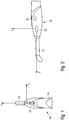
- the light curing device 10 shown has a bent light guide 12 and a housing 14 in a manner known per se.
- the housing 14 accommodates a light source, which feeds the emitted light to the light guide 12, and also an energy source, in the embodiment shown in the form of an accumulator.
- Control device 16 shown schematically, controls the polymerization cycle of the light curing device 10.
- a switch 18 is provided on the housing 14, in the exemplary embodiment on the upper side of the essentially pin-shaped and / or pistol-shaped light curing device 10.
- the light curing device 10 also has a sensor 20, which in the exemplary embodiment shown is designed as a translational motion sensor.
- the sensor 20 therefore transmits movement data of the light curing device 10, which it detects, to the control device 16; this effects the action of the light curing device 10 that is required based on the movement.
- the motion sensor 20 is designed as a translational motion sensor. It detects movements of the light curing device in three spatial directions, of which in Fig. 1 the spatial directions x and y and in Fig. 2 the spatial directions y and z are shown.
- the light curing device 10 when it is turned off or is in a rest position, detects any movement.
- the dentist picks up the light curing device, a movement takes place, and based on the correspondingly detected movement signal from the sensor 20, the control device 16 transfers the light curing device 10 from an idle state to the ready state.
- the light curing device 10 While all energy-intensive circuits of the light curing device are switched off in the idle state and only the motion sensor is supplied with a very low current, the light curing device 10 is ready in the ready state to start a polymerization cycle immediately, that is to say without delay.
- the circuits required for this, i.e. the actual control of the light curing device, are supplied with current for this purpose.
- the current consumption of the light curing device is very low in the idle state and is, for example, 1 ⁇ A or even only 100nA, while in the standby state there is a current consumption of, for example, 20mA.
- the current consumption during the standby state can accordingly be in the order of magnitude of the current consumption of the polymerization cycle.
- an idle state is possible in which the power consumption is drastically reduced, i.e. by several powers of ten, and the runtime of the accumulator used is accordingly increased without delays in the start program of the microprocessor for the Polymerization cycle result - the microprocessor is of course switched off in the idle state.
- Fig. 3 a modified light curing device can be seen.
- These, as well as the others, are provided with corresponding or identical reference symbols for corresponding parts, so that the reference symbols do not have to be explained again.
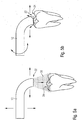
- the sensor 20 is also designed as a motion sensor, but as a rotation sensor. In contrast, this has a different function, which is related to the polymerization.
- the tip 22 of the light guide 12 is in direct and, if possible, almost direct contact with the dental restoration to be polymerized.
- the dentist typically holds the light curing device 10 on the housing 14.
- the switch 18 is equipped with suitable displays such as LED displays in order to signal the operating state, so that this area is frequently left free when gripping.
- the tip 22 moves away from the target area, ie the dental restoration. Due to the length of the light curing device 10, there is already a very slight rotation about the Z axis according to Fig. 4 to a strong shift in tip 22.
- the senor 20 according to the invention in the configuration as a rotation sensor counteracts a resulting incorrect polymerization, because the control device 16 generates suitable signaling based on its output signal during the polymerization cycle.
- the representation is in accordance with Fig. 5a the tip 22 of the light guide 12 is spaced significantly more from the dental restoration 24. Because of the beam widening 30, the exposure intensity of the dental restoration 24 is lower, and there is now the possibility of either emitting a position correction signal or, according to the invention, of automatically extending the exposure time.
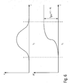
- the top curve out Figure 6 shows an accidental shift, for example in the x direction. If the shift exceeds a certain threshold value, for example at time t 1 , an error signal is transmitted to the dentist. After its reaction time, the light curing device should be brought back to the correct position.
- the effective polymerization time would be too short, and therefore, according to the invention, the polymerization time is extended by the value ⁇ T, corresponding to the time in which the shift to the incorrect position exists.
- this increases the polymerization time to t tot .
- this is less significant than incorrect polymerisation, which is known to have serious consequences.
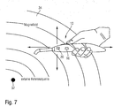
- the light curing device is in any case designed as a handheld device and has either an external or an internal power source.
- the in Fig. 7 is shown schematically, an external reference source 32 is realized, which generates a magnetic field.
- external reference sources 32 which each generate magnetic fields 34, are realized in this embodiment, and the exact position can be determined by triangulation in a manner known per se.
- the senor 20 is designed as a magnetic field sensor.
- a distance sensor at the tip 22 of the light curing device 10.
- the distance sensor can be implemented, for example, by means of ultrasound or as a laser range finder.
- the position of the light curing device 10 relative to the treatment surface, that is to say the dental restoration, can thereby be determined directly.
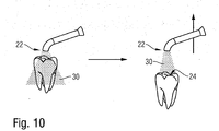
- Fig. 10 shows schematically how the light expansion 30 in combination with the distance of the tip 22 from the dental restoration 24 has effects on the radiation.
- a small distance is sufficient to also apply to a large-area dental restoration.
- the beam expansion 30 shown on the right a larger distance is required in order to act on the entire large-area dental restoration.
- the motion sensor according to the invention can not only determine this, but it can also be signaled or corrected.
Description
Die Erfindung betrifft ein Lichthärtgerät, insbesondere ein dentales Lichthärtgerät für zu polymerisierendes Material wie PMMA oder Komposit und Adhäsive, Zemente sowie für die Anregung beliebiger Photoinitiatoren, gemäß dem Oberbegriff von Anspruch 1.The invention relates to a light curing device, in particular a dental light curing device for material to be polymerized, such as PMMA or composite and adhesives, cements and for the excitation of any photoinitiators, according to the preamble of
Derartige Lichthärtgeräte sind seit langem bekannt und werden im großen Umfang eingesetzt, wenn es gilt, Komposits oder PMMA-Dentalrestaurationen zu polymerisieren und auszuhärten.Such light curing devices have long been known and are used on a large scale when it is a matter of polymerizing and curing composites or PMMA dental restorations.
Für die Polymerisation der Dentalrestaurationen ist es erforderlich, diesen eine vorgegebene Lichtmenge zuzuleiten, was impliziert, dass nicht die Abgabe der Lichtmenge durch das Lichthärtgerät, sondern die Zuleitung der Lichtmenge zur Dentalrestauration entscheidend ist.For the polymerization of the dental restorations, it is necessary to supply them with a predetermined amount of light, which implies that it is not the emission of the amount of light by the light curing device, but the supply of the amount of light to the dental restoration that is decisive.
Seit langem ist es bekannt, hierzu sogenannte Lichtdosierungssensoren zu verwenden, wozu beispielhaft auf die
Wenn das Lichtauslassende des als Handgerät ausgebildeten Lichthärtgeräts in den Raum der Mundhöhle - aber nicht auf die Zähne - gerichtet ist, wird nahezu kein Licht reflektiert, so dass die dortige Dosiereinrichtung dieses Fehllicht bei der Bemessung der abzugebenen Lichtmenge berücksichtigt.If the light outlet end of the light curing device designed as a hand-held device is directed into the oral cavity - but not towards the teeth - almost no light is reflected, so that the metering device there takes this false light into account when measuring the amount of light to be emitted.
Wenn andererseits das Lichtauslassende auf einen Zahn gerichtet ist, jedoch neben das Restaurationsmaterial, erfolgt eine Reflektion des abgegebenen Lichts zur Dosiereinrichtung hin. Dieses reflektierte Licht wird von der Dosiereinrichtung nicht als Fehllicht berücksichtigt, und die Zeit, in der von der Lichtquelle des Lichthärtgeräts Licht abgegeben wird, wird bei der Berechnung des Polymerisationszyklus, also der gesamten Belichtungszeit des Dentalrestaurationsteils, berücksichtigt.If, on the other hand, the light outlet end is directed towards a tooth, but next to the restoration material, the emitted light is reflected towards the metering device. This reflected light is not taken into account by the metering device as false light, and the time in which light is emitted by the light source of the light curing device is taken into account in the calculation of the polymerization cycle, that is to say the total exposure time of the dental restoration part.
Dies führt zu einer Fehlkalkulation, denn tatsächlich wird durch die Beaufschlagung von benachbarten Zähnen - oder beispielsweise benachbarten, bereits ausgehärteten Dentalrestaurationen -, keine bzw. unzureichende Polymerisation vorgenommen.This leads to a miscalculation because, in fact, the application of adjacent teeth - or, for example, adjacent, already hardened dental restorations - results in no or inadequate polymerization.
Zwar soll durch ein Polarisationsfilter, der aber verzichtbar sein soll, eine Unterscheidung von Arten des reflektierten Lichts realisiert werden. Dies ist aber mindestens dann nicht möglich, wenn das Licht von einer benachbarten, ausgehärteten Dentalrestauration reflektiert wird.A distinction between types of reflected light is to be realized by a polarization filter, which should however be dispensable. However, this is at least not possible if the light is reflected from an adjacent, hardened dental restoration.
Diese Lösung hat sich daher - insofern nicht ganz überraschend - nicht durchgesetzt.In this respect, it is not entirely surprising that this solution has not become established.
Auch bei stationären Lichthärtgeräten sind Sensoren bekannt geworden, die der Steuerung des Lichthärtgeräts dienen. Beispielsweise sei hier auf die
Auch bei diesen Lösungen ist jedoch eine Fehlbelichtung möglich, beispielsweise, wenn der Finger des Benutzers sich dem optischen Näherungssensor nähert, bevor das Dentalrestaurationsteil in den Lichtkegel gebracht wird.However, incorrect exposure is also possible with these solutions, for example if the user's finger approaches the optical proximity sensor before the dental restoration part is brought into the light cone.
Die
Auch die
Die
Die bislang bekannten Lichthärtgeräte erzeugen bei einer Fehlbedienung regelmäßig Fehlhärtungen, was umso kritischer ist, da heutzutage der Verbleib von Monomeren mit ihren freien Radikalen im Mund des Patienten häufig als Haftungsfall für die Zahnarzt angesehen wird.The previously known light curing devices regularly produce incorrect curing when operated incorrectly, which is all the more critical since the presence of monomers with their free radicals in the patient's mouth is often regarded as a liability for the dentist.
Demgegenüber liegt der Erfindung die Aufgabe zu Grunde, ein Lichthärtgerät gemäß dem Oberbegriff von Anspruch 1 zu schaffen, das neben der verbesserten Sicherheit der Bedienung auch eine verbesserte Ergonomie bietet.In contrast, the invention is based on the object of creating a light curing device according to the preamble of
Diese Aufgabe wird erfindungsgemäß durch Anspruch 1 gelöst. Vorteilhafte Weiterbildungen ergeben sich aus den Unteransprüchen.This object is achieved by
Durch die Realisierung eines Ortsensors und/oder eines Bewegungssensors und/oder eines Winkelsensors und/oder eines Magnetfeldsensors und/oder deren Kombination als Teil des Lichthärtgeräts lassen sich gleich mehrere Vorteile erzielen. Der eingesetzte Sensor kann beispielsweise verwendet werden, um sicherzustellen, dass das Lichthärtgerät an der Stelle verbleibt, an der der Zahnarzt es beim Einschalten zur Polymerisation eingesetzt hat.By implementing a location sensor and / or a motion sensor and / or an angle sensor and / or a magnetic field sensor and / or their combination as part of the light curing device, several advantages can be achieved. The sensor used can be used, for example, to ensure that the light curing device remains at the point at which the dentist used it for the polymerization when it was switched on.
Damit soll sichergestellt werden, dass - wenn überhaupt eine Polymerisation vorgenommen wird - diese vollständig vorgenommen wird. Der Zahnarzt erkennt demgegenüber ohne weiteres das unpolymerisierte Dentalrestaurationsteil, da es weich bzw. nahezu flüssig ist. In diesem Zusammenhang sei darauf hingewiesen, dass der Zahnarzt nicht ohne weiteres erkennen kann, wenn die Oberfläche des Inkrements aushärtet, in der Tiefe/auf der Unterseite der Füllung aber keine Aushärtung stattfindet.This is to ensure that - if a polymerization is carried out at all - it is carried out completely. In contrast, the dentist readily recognizes the unpolymerized dental restoration part, since it is soft or almost liquid. In this context, it should be pointed out that the dentist cannot readily recognize when the surface of the increment is curing but there is no curing in the depth / on the underside of the filling.
Gemäß einem vorteilhaften Aspekt der Erfindung geht diese von dem Gedanken aus, dass, wenn der Zahnarzt das Lichthärtgerät an der richtigen Stelle ansetzt und die Belichtung auslöst, also den Polymerisationszyklus startet, dieser auch ordnungsgemäß vorgenommen wird, wenn er das Gerät nicht versehentlich weg bewegt.According to an advantageous aspect of the invention, this is based on the idea that if the dentist places the light curing device in the right place and triggers the exposure, that is to say starts the polymerization cycle, this is also carried out properly if he does not accidentally move the device away.
Dies lässt sich mit den erfindungsgemäßen Ortsensoren bzw. Bewegungssensoren bzw. Magnetfeldsensoren bzw. Gyrosensoren bzw. deren Kombination sicherstellen, die erfassen, wenn das Lichthärtgerät nach dem Start der Belichtung weg bewegt wird.This can be ensured with the position sensors or motion sensors or magnetic field sensors or gyro sensors or their combination according to the invention, which detect when the light curing device is moved away after the start of the exposure.
Hierzu sind die erfindungsgemäßen Sensoren bevorzugt als Relativsensoren und/oder Absolutsensoren ausgebildet. Ein derartiger Ortsensor erkennt eine Bewegung des Handgeräts, als das das Lichthärtgerät ausgebildet ist, in einer der drei Raumrichtungen oder Dimensionen, bevorzugt aber auch eine Winkeländerung.For this purpose, the sensors according to the invention are preferably designed as relative sensors and / or absolute sensors. Such a location sensor detects a movement of the hand-held device as the light curing device is designed, in one of the three spatial directions or dimensions, but preferably also a change in angle.
In diesem Zusammenhang ist es erfindungsgemäß bevorzugt, Grenzwerte vorzusehen, ab welchen eine Bewegung als kritisch angesehen wird. Beispielsweise kann eine Winkelabweichung der Ausrichtung des Lichtstrahls, der von dem Lichtauslassende abgegeben wird, deutlich kritischer sein als eine Verlagerung des Lichthärtgeräts in axialer Richtung, also in Richtung des Lichtabgabeelements, um einen oder mehrere Milimeter. Die Winkelabweichung würde dazu führen, dass das Zielgebiet des Lichtabgabelements, also die Dentalrestauration oder die Bearbeitungsoberfläche, deutlich verfehlt wird, während eine winkeltreue Verlagerung des Handgeräts in rückwärtiger Richtung lediglich zur - in der Regel geringen - Reduktion der aufgebrachten Lichtleistung führt.In this context, it is preferred according to the invention to provide limit values above which a movement is regarded as critical. For example, an angular deviation in the alignment of the light beam emitted by the light outlet end can be significantly more critical than a displacement of the light curing device in the axial direction, that is to say in the direction of the light emitting element, by one or more millimeters. The angular deviation would lead to the target area of the light-emitting element, i.e. the dental restoration or the processing surface, being clearly missed, while an angularly accurate shifting of the hand-held device in the rearward direction only leads to a - generally small - reduction in the applied light output.
Darüber hinaus ist es auch möglich, die durch den erfindungsgemäßen Ortsensor und/oder Bewegungssensor erfassten Parameter, die als Signale der erfindungsgemäßen Steuereinrichtung zugeleitet werden, auszuwerten, um eine Aktion oder Funktion des Lichthärtgeräts auszulösen.In addition, it is also possible to evaluate the parameters detected by the position sensor and / or motion sensor according to the invention, which are supplied as signals to the control device according to the invention, in order to trigger an action or function of the light curing device.
Beispielsweise kann das Aufnehmen eines auf einer Unterlage abgelegten Handgeräts, als das das Lichthärtgerät ausgebildet ist, dazu erfasst werden, und die Erfassung dazu genutzt werden, das Lichthärtgerät in einen aktiven Zustand zu schalten, in dem unmittelbar der Polymerisationszyklus bei Bedarf gestartet werden kann.For example, the recording of a handheld device placed on a base, as the light curing device is designed, can be recorded and the recording can be used to switch the light curing device into an active state in which the polymerization cycle can be started immediately if required.
Bei dieser Ausgestaltung ist das Lichthärtgerät bevorzugt in abgelegtem Zustand in einem Ruhezustand, der die für den Betrieb verwendeten Akkumulatoren schont. Die Aufnahme des Lichthärtgeräts ist mit einer Bewegung verbunden, die von den erfindungsgemäßen Sensoren erfasst wird.In this embodiment, the light curing device is preferably in a stored state in a rest state, which protects the batteries used for operation. The inclusion of the light curing device is associated with a movement that is detected by the sensors according to the invention.
Auch ist es möglich, durch gezielte Bewegungen, wie beispielsweise ein Schütteln, wie es bei Smartphone bekannt geworden ist, eine bestimmte Funktion auszulösen, wie beispielsweise einen Programmwechsel.It is also possible to trigger a specific function, for example a program change, by means of targeted movements, such as shaking, as has become known for smartphones.
Es versteht sich, dass bevorzugt der aktuelle Zustand des erfindungsgemäßen Lichthärtgeräts über einen hierfür geeignete Anzeige, wie eine Flüssigkristallanzeige, signalisiert wird.It goes without saying that the current state of the light curing device according to the invention is preferably signaled via a suitable display, such as a liquid crystal display.
Bei einer unabsichtlichen Verlagerung, wie beispielsweise einer allzu starken Winkelabweichung währen des Polymerisierens, oder auch beispielsweise beim Fallenlassen des Handgeräts, lässt sich ein Alarm auslösen und/oder das betreffende Ereignis protokollieren, was auch als Nachweis für Garantieansprüche ausgenutzt werden kann. Die Ortserfassung kann in an sich bekannter Weise über Triangulation gegenüber mindestens drei vorgegebenen Referenzquellen realisiert sein. Zu den in Frage kommenden Medien gehören elektromagnetische, aber auch Ultraschall- oder Infrarotquellen. Auch ist es möglich, über eine Kamera eine Bilderkennung vorzunehmen und hierdurch die Lageänderung zu erfassen. Bevorzugt erfolgt die Erkennung der Verlagerung oder Bewegung relativ, also bevorzugt bezogen auf einen Referenzpunkt, eine Referenzposition oder eine Referenzwinkellage.In the event of an unintentional shift, such as an excessive angle deviation during polymerisation, or also, for example, when the handheld device is dropped, an alarm can be triggered and / or the event in question can be logged, which can also be used as proof of warranty claims. The location detection can be implemented in a manner known per se via triangulation with respect to at least three predetermined reference sources. The media in question include electromagnetic, but also ultrasound or infrared sources. It is also possible to carry out image recognition via a camera and thereby to detect the change in position. The displacement or movement is preferably detected relatively, that is to say preferably with reference to a reference point, a reference position or a reference angular position.
Es ist auch möglich, bei einer geringen Abweichung von der erwünschten Position und/oder Winkelausrichtung die Lichtleistung gegebenenfalls kurzzeitig zu erhöhen und/oder erfindungsgemäß die Belichtungszeit zu verlängern, um dennoch eine ordnungsgemäße Polymerisation zu gewährleisten und die erforderliche Gesamtlichtdosis zu erreichen. Durch die Erfassung der Positionsabweichung oberhalb eines ersten Schwellenwerts wird bei dieser Lösung mindestens eine Kompensationsmaßnahme eingeleitet, während bei Erfassung einer Abweichung oberhalb eines zweiten oder weiteren Schwellenwerts (auch mehr als zwei) eine Signalisierung vorgenommen wird, eine Abspeicherung und/oder eine Ausschaltung des Lichthärtgeräts.It is also possible, if there is a slight deviation from the desired position and / or angular orientation, to briefly increase the light output, if necessary, and / or to extend the exposure time according to the invention, in order nevertheless to ensure proper polymerization and to achieve the required total light dose. By detecting the position deviation above a first threshold value, at least one compensation measure is initiated in this solution, while when a deviation is detected above a second or further threshold value (also more than two), signaling is carried out, the light curing device is stored and / or switched off.
Zu den Möglichkeiten, die Fehlstellung zu kompensieren, zählt auch die Nachführung des Lichtkegels bzw. die Änderung der Fokusierung, was die Verlagerung entsprechender Linsen und/oder Reflektoren bedingt.The possibilities of compensating for the incorrect position also include tracking the light cone or changing the focus, which necessitates the shifting of the corresponding lenses and / or reflectors.
Es ist auch möglich, eine Minikamera auf die Bearbeitungsoberfläche zu richten und die Nachführung per Bilderkennung dann automatisch erfolgen zu lassen, wenn eine Verlagerung festgestellt wird. In diesem Fall dient insofern die Minikamera als Bewegungssensor bzw. Ortsensor.It is also possible to point a mini camera at the processing surface and to have the tracking automatically performed by image recognition if a shift is detected. In this case, the mini camera serves as a motion sensor or location sensor.
Weitere Vorteile, Einzelheiten und Merkmale ergeben sich aus der nachfolgenden Beschreibung mehrerer Ausführungsbeispiele anhand der Zeichnung.Further advantages, details and features result from the following description of several exemplary embodiments with reference to the drawing.
Es zeigen:
- Fig. 1
- Eine schematische Ansicht eines erfindungsgemäßen Lichthärtgeräts, unter Einbeziehung von zwei Raumkoordinaten;
- Fig. 2
- das Ausführungsbeispiel gemäß
Fig. 1 in eine Queransicht und dementsprechend unter Darstellung von zwei anderen Raumkoordinaten; - Fig. 3
- eine modifizierte Ausführungsform des erfindungsgemäßen Lichthärtgeräts, das einen Rotationssensor aufweist;
- Fig. 4
- eine Darstellung des Lichthärtgeräts gemäß
Fig. 3 in einer anderen Ansicht; - Fig. 5a und 5b
- zwei Darstellungen der Handhabung eines Teils des erfindungsgemäßen Lichthärtgeräts, wobei der Abstand und die Relativposition zu einem zu behandelnden Zahn erfasst wird;
- Fig. 6
- eine Darstellung der Verlängerung der Belichtungszeit bei Erfassung einer Winkelabweichung;
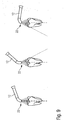
- Fig. 7
- eine Darstellung einer weiteren Ausführungsform eines erfindungsgemäßen Lichthärtgeräts bei welchen ein Magnetfeld erfasst wird;
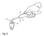
- Fig. 8
- eine weitere Ausführungsform eines erfindungsgemäßen Lichthärtgeräts mit Ultraschall- oder Laserentfernungsmesser;
- Fig. 9
- eine weitere Ausführungsform eines erfindungsgemäßen Lichthärtgeräts; und
- Fig. 10
- eine weitere Ausführungsform eines erfindungsgemäßen Lichthärtgeräts.
- Fig. 1
- A schematic view of a light curing device according to the invention, including two spatial coordinates;
- Fig. 2
- the embodiment according to
Fig. 1 in a transverse view and accordingly showing two other spatial coordinates; - Fig. 3
- a modified embodiment of the light curing device according to the invention, which has a rotation sensor;
- Fig. 4
- a representation of the light curing device
Fig. 3 in a different view; - 5a and 5b
- two representations of the handling of a part of the light curing device according to the invention, the distance and the relative position to a tooth to be treated being recorded;
- Fig. 6
- a representation of the extension of the exposure time when detecting an angular deviation;
- Fig. 7
- a representation of a further embodiment of a light curing device according to the invention in which a magnetic field is detected;
- Fig. 8
- a further embodiment of a light curing device according to the invention with ultrasonic or laser range finder;
- Fig. 9
- a further embodiment of a light curing device according to the invention; and
- Fig. 10
- a further embodiment of a light curing device according to the invention.
Das in
Erfindungsgemäß weist das Lichthärtgerät 10 ferner einen Sensor 20 auf, der im dargestellten Ausführungsbeispiel als translatorischer Bewegungssensor ausgebildet ist. Der Sensor 20 gibt daher Bewegungsdaten des Lichthärtgeräts 10, die er erfasst, an die Steuereinrichtung 16 weiter; diese bewirkt die basierend auf der Bewegung erforderliche Aktion des Lichthärtgeräts 10.According to the invention, the
In diesem Ausführungsbeispiel ist der Bewegungssensor 20 als translatorischer Bewegungssensor ausgeführt. Er erfasst Bewegungen des Lichthärtgeräts in drei Raumrichtungen, von denen in
Als beispielhafte Anwendung ist es bei dieser Ausführungsform vorgesehen, dass das Lichthärtgerät 10, wenn es denn abgestellt ist bzw. in einer Ruheposition ist, eine Bewegung in beliebiger Art erfasst. Wenn der Zahnarzt das Lichthärtgerät aufnimmt, erfolgt eine Bewegung, und basierend auf dem entsprechend erfassten Bewegungssignal des Sensors 20 überführt die Steuereinrichtung 16 das Lichthärtgerät 10 von einem Ruhezustand in den Bereitschaftszustand.As an exemplary application, it is provided in this embodiment that the
Während im Ruhezustand sämtliche energieintensiven Schaltkreise des Lichthärtgeräts abgeschaltet sind und lediglich der Bewegungssensor mit einem ganz geringen Strom versorgt wird, ist das Lichthärtgerät 10 im Bereitschaftszustand bereit, um unmittelbar, also verzögerungsfrei, einen Polymerisationszyklus zu starten. Die hierfür erforderlichen Stromkreise, also die eigentliche Steuerung des Lichthärtgeräts, werden hierzu mit Strom versorgt. In der Praxis ist der Strombedarf des Lichthärtgeräts im Ruhezustand ganz gering und beträgt beispielsweise 1µA oder sogar nur 100nA, während im Bereitschaftszustand ein Stromverbrauch von beispielsweise 20mA entsteht.While all energy-intensive circuits of the light curing device are switched off in the idle state and only the motion sensor is supplied with a very low current, the
Es ist auch möglich, im Bereitschaftszustand einen Kondensator hoher Kapazität wie beispielsweise 10F, aufzuladen und hierfür beispielsweise einen Strom von einem 1A mit Start des Bereitschaftszustands diesem Kondensator zuzuleiten.It is also possible to charge a capacitor of high capacitance, such as 10F, in the standby state and, for this purpose, to feed a current from a 1A to this capacitor when the standby state starts.
Der Stromverbrauch während des Bereitschaftszustands kann bei dieser Ausgestaltung dementsprechend in der Größenordnung des Stromverbrauchs des Polymerisationszyklus sein.The current consumption during the standby state can accordingly be in the order of magnitude of the current consumption of the polymerization cycle.
Erfindungsgemäß ist es bei dieser Ausführungsform daher besonders günstig, dass ein Ruhezustand möglich ist, in welchem der Stormverbrauch drastisch, also um mehrere Zehnerpotenzen, reduziert ist und daher die Laufzeit des verwendeten Akkumulators entsprechend erhöht wird, ohne dass sich Verzögerungen beim Startprogramm des Mikroprozessors für den Polymerisationszyklus ergeben - der Mikroprozessor ist natürlich im Ruhezustand abgeschaltet.According to the invention, it is therefore particularly favorable in this embodiment that an idle state is possible in which the power consumption is drastically reduced, i.e. by several powers of ten, and the runtime of the accumulator used is accordingly increased without delays in the start program of the microprocessor for the Polymerization cycle result - the microprocessor is of course switched off in the idle state.
Aus
Bei dem Mikroprozessor gemäß den
Beim Polymerisieren muss darauf geachtet werden, dass die Spitze 22 des Lichtleiters 12 unmittelbar und nach Möglichkeit in nahezu direktem Kontakt mit der zu polymerisierenden Dentalrestauration ist. Der Zahnarzt fasst das Lichthärtgerät 10 typischerweise am Gehäuse 14. Der Schalter 18 ist mit geeigneten Anzeigen wie LED-Anzeigen bestückt, um den Betriebszustand zu signalisieren, so dass dieser Bereich beim Greifen häufig freigelassen wird.When polymerizing, care must be taken that the
Wenn nun während der Polymerisation der Zahnarzt beispielsweise abgelenkt wird oder unabsichtlich eine unwillkürliche Bewegung der Hand ausführt, entfernt sich die Spitze 22 von dem Zielgebiet, also der Dentalrestauration. Aufgrund der Länge des Lichthärtgeräts 10 führt bereits eine ganz geringe Rotation um die Achse Z gemäß
Erfindungsgemäß wirkt einer hierdurch indizierten Fehlpolymerisation der erfindungsgemäßse Sensor 20 in der Ausgestaltung als Rotationssensor entgegen, denn basierend auf dessen Ausgangssignal während des Polymerisationszyklus erzeugt die Steuervorrichtung 16 eine geeignete Signalisierung.According to the present invention, the
Es ist auch möglich, die Korrekturbewegungsrichtung anzuzeigen; wenn die Spitze 22 beispielsweise versehentlich nach links geschwenkt wird, wird im Bereich der Anzeige des Schalters 18 ein Signal eingeblendet "nach rechts drehen".It is also possible to display the direction of correction movement; if, for example, the
Dies kann durch entsprechende Piktogramme, eine beliebige andere Visualisierung oder beispielsweise auch durch Sprachausgabe realisiert werden.This can be achieved by means of appropriate pictograms, any other visualization or, for example, by voice output.
Aus
Demgegenüber ist in der Darstellung gemäß
Er versteht sich, dass auch die Kombination beider Möglichkeiten besteht, also die Belichtungszeit so lange zu verlängern, bis der Zahnarzt die Fehlpositionierung merkt und dann die Spitze 22 wieder in die Position gemäß
Es versteht sich, dass auch bei einer seitlichen Verlagerung der Spitze 22 Fehlhärtungen entstehen können. Je nach Abmessung der Dentalrestauration 24 im Verhältnis zum Emissionsdurchmesser der Spitze 22 sind diese sogar kritischer als eine Abstandsveränderung, was erfindungsgemäß mit dem Lagesensor 20 kompensiert werden soll.It goes without saying that 22 incorrect hardening can also occur when the tip is displaced laterally. Depending on the dimension of the
Aus
Ohne erfindungsgemäßen Sensor würde die wirksame Polymerisationszeit jedoch zu kurz sein, und daher wird erfindungsgemäß die Polymerisationszeit um den Wert ΔT, entsprechend der Zeit, in der die Verlagerung in die Fehlpostion besteht, verlängert.Without the sensor according to the invention, however, the effective polymerization time would be too short, and therefore, according to the invention, the polymerization time is extended by the value ΔT, corresponding to the time in which the shift to the incorrect position exists.
Zwar verlängert sich erfindungsgemäß dadurch die Polymerisationszeit auf tges. Dies ist jedoch weniger bedeutsam als eine Fehlpolymerisation, die bekanntlich auch gravierende Folgen haben kann.According to the invention, this increases the polymerization time to t tot . However, this is less significant than incorrect polymerisation, which is known to have serious consequences.
Aus
Es versteht sich, dass das Lichthärtgerät jedenfalls als Handgerät ausgebildet ist und entweder eine externe oder eine interne Stromquelle aufweist. In dieser Ausführungsform, die in
In der Praxis sind mindestens 1, bevorzugt 3 externe Referenzquellen 32, die je Magnetfelder 34 erzeugen, bei dieser Ausführungsform realisiert, und in an sich bekannter Weise lässt sich die exakte Position durch Triangulation feststellen.In practice, at least 1, preferably 3,
Der Sensor 20 ist in dem dargestellten Ausführungsbeispiel als Magnetfeldsensor ausgebildet.In the exemplary embodiment shown, the
Bei der Ausführungsform gemäß
Aus
Insofern besteht stets ein optimaler Abstand zwischen der Spitze 22 und der Dentalrestauration 24, und der erfindungsgemäße Bewegungssensor kann diesen nicht nur feststellen, sondern er kann auch signalisiert bzw. korrigiert werden.In this respect, there is always an optimal distance between the
In der Ausführungsform gemäß
Claims (15)
- A light curing device (10), comprising a light source and a light emitting element such as a light guide (12), the light emitting end of which light guide is adapted to be directed onto a material to be polymerized, one or more control device (16) being provided for switching on the light source during a polymerization cycle, and one or more sensors (20) or sensor combinations which is/are connected to the at least one control device (16), wherein a sensor (20) is designed as a movement sensor (20) which is suitable for detecting a movement of the light-curing device (10) designed as a hand-held device, and guiding signals, which represent the movement, to the control device (16), characterized in that the at least one control device (16) is designed to determine, via the movement sensor (20) at the beginning of the polymerization cycle, an optimum position of the light-emitting element relative to the material to be polymerized and to extend the polymerization cycle if, based on the signals of the movement sensor (20), a deviation from this position occurs during the polymerization cycle, proportional to the degree of the deviation and in particular the duration of the deviation.
- The light curing device according to claim 1, characterized in that the control device detect the position of the light emitting element in relation to the material to be polymerized.
- The light curing device according to one of claims 1 or 2, characterized in that the at least one control device (16) is connected to a light sensor and/or a camera which is/are connected to the light curing device (10) designed as a hand-held device and is/are directed towards the material to be polymerized or the treatment surface, and in that the optimum position of the light curing device (10) for the polymerization cycle is allowed to be determined based on the output signals of the light sensor and/or the camera.
- The light curing device according to one of the preceding claims, characterized in that at least one movement sensor (20) is designed as a relative movement sensor which detects a relative movement in all three dimensions in relation to the position and/or inclination of the hand-held device at the start of exposure, i.e. at the start of the polymerization cycle.
- The light curing device according to one of the preceding claims, characterized in that at least one sensor is configured as a gyro sensor or angle sensor.
- The light curing device according to one of the preceding claims, characterized in that the light curing device (10) also comprises a base station which generates a reference field, and that a sensor (20), in particular a magnetic sensor, detects a change of location and/or movement and/or acceleration in the reference field, in particular in at least two dimensions.
- The light curing device according to one of the preceding claims, characterized in that at least one sensor (20) of the hand-held device comprises a position detection mechanism via triangulation of GPS satellites, via radio transmitters, via electromagnetic fields and/or via ultrasound and/or infrared.
- The light curing device according to one of the preceding claims, characterized in that the hand-held device comprises a location sensor for detecting the distance to the treatment surface, i.e. to the material to be polymerized, which sensor detects the distance via the changing brightness of a predetermined reference light beam.
- The light curing device according to one of the preceding claims, characterized in that the control device (16) adapts and controls the exposure time, i.e. the length of the polymerization cycle, depending on the signal of the sensor or sensors (20) and, in the event of malposition and/or displacement of the handpiece, extends the exposure time or switches off the light device when a termination criterion/threshold value is reached.
- The light curing device according to one of the preceding claims, characterized in that the control device (16) increases irradiation intensity, in particular for a short time, in the event of malpositioning/movement above one or more predetermined threshold values or switches off the light device when reaching a termination criterion/threshold value.
- The light curing device according to one of the preceding claims, characterized in that the control device (16) signals malpositioning of the light curing device (10) during the polymerization cycle, in particular based on the signals detected by the sensor(s) (20), to the user by means of a suitable feedback, in particular by vibration and/or by means of acoustic/visual signaling, in particular by a luminous LED in the housing (14), and/or by switching off the light curing device (10).
- The light curing device according to claim 11, characterized in that using the control device in the event of a malposition detected by the sensor or sensors (20), which is different from the starting position from a predetermined threshold value, the light cone emitted by the light-emitting end can be tracked by a deflecting device such as a reflector or a lens.
- The light curing device according to one of the preceding claims, characterized in that at least one movement sensor (20) is configured as an acceleration sensor and, in the event of acceleration being above a predetermined value, the control device (16) evaluates and stores said acceleration in order to detect excessive vibration of the light curing device (10).
- The light curing device according to one of the preceding claims, characterized in that the control device processes a combination of acceleration sensor, gyro sensor and magnetic field sensor and their individual signals to form a total signal and the noise or malinformation is compensated and a constant signal may be generated.
- The light curing device according to one of the preceding claims, characterized in that the control device regulates or increases the focusing of the light output as a function of the movement/malposition of the handpiece, thus locally increasing the irradiance.
Priority Applications (4)
| Application Number | Priority Date | Filing Date | Title |
|---|---|---|---|
| ES14167896T ES2802819T3 (en) | 2014-05-12 | 2014-05-12 | Light curing device, in particular dental light curing device |
| EP14167896.1A EP2944288B1 (en) | 2014-05-12 | 2014-05-12 | Light curing device, in particular dental light curing device |
| PCT/EP2015/060180 WO2015173136A1 (en) | 2014-05-12 | 2015-05-08 | Light curing appliance, in particular dental light curing appliance |
| US15/037,819 US11523889B2 (en) | 2014-05-12 | 2015-05-08 | Light curing appliance, in particular dental light curing appliance |
Applications Claiming Priority (1)
| Application Number | Priority Date | Filing Date | Title |
|---|---|---|---|
| EP14167896.1A EP2944288B1 (en) | 2014-05-12 | 2014-05-12 | Light curing device, in particular dental light curing device |
Publications (2)
| Publication Number | Publication Date |
|---|---|
| EP2944288A1 EP2944288A1 (en) | 2015-11-18 |
| EP2944288B1 true EP2944288B1 (en) | 2020-04-08 |
Family
ID=50687327
Family Applications (1)
| Application Number | Title | Priority Date | Filing Date |
|---|---|---|---|
| EP14167896.1A Active EP2944288B1 (en) | 2014-05-12 | 2014-05-12 | Light curing device, in particular dental light curing device |
Country Status (4)
| Country | Link |
|---|---|
| US (1) | US11523889B2 (en) |
| EP (1) | EP2944288B1 (en) |
| ES (1) | ES2802819T3 (en) |
| WO (1) | WO2015173136A1 (en) |
Families Citing this family (8)
| Publication number | Priority date | Publication date | Assignee | Title |
|---|---|---|---|---|
| JP2017533058A (en) | 2014-09-17 | 2017-11-09 | ギャリソン デンタル ソリューションズ,リミティド ライアビリティ カンパニー | Dental curing light |
| WO2016164238A1 (en) * | 2015-04-10 | 2016-10-13 | 3M Innovative Properties Company | A dental light irradiation device |
| USD828563S1 (en) * | 2015-08-14 | 2018-09-11 | Ivoclar Vivadent Ag | Control module for a dental light hardening device |
| US20170215698A1 (en) * | 2016-01-28 | 2017-08-03 | Dental Wings Inc. | System and method for providing user feedback indications during intra-oral scanning process |
| EP3222245B1 (en) * | 2016-03-22 | 2021-09-22 | Dentsply Sirona Inc. | Method and arrangement for cleaning of a canal |
| US10746660B2 (en) | 2016-07-29 | 2020-08-18 | 3M Innovative Properties Company | Cure monitoring systems and methods |
| EP3636159B1 (en) * | 2018-10-09 | 2024-04-24 | Ivoclar Vivadent AG | Dental tool control system |
| US11589971B2 (en) * | 2018-11-14 | 2023-02-28 | Garrison Dental Solutions, L.L.C. | Dental curing light and method |
Citations (1)
| Publication number | Priority date | Publication date | Assignee | Title |
|---|---|---|---|---|
| US20130268033A1 (en) * | 2010-12-21 | 2013-10-10 | Koninklijke Philips Electronics N.V. | Light therapy device |
Family Cites Families (37)
| Publication number | Priority date | Publication date | Assignee | Title |
|---|---|---|---|---|
| DE8219588U1 (en) | 1982-07-08 | 1985-02-07 | ESPE Fabrik pharmazeutischer Präparate GmbH, 8031 Seefeld | DEVICE FOR TREATING DENTAL SPARE PARTS AND DENTAL MATERIALS WITH RADIATION |
| DE3225589A1 (en) | 1982-07-08 | 1984-01-12 | ESPE Fabrik pharmazeutischer Präparate GmbH, 8031 Seefeld | DEVICE FOR TREATING DENTAL SPARE PARTS AND DENTAL MATERIALS WITH RADIATION |
| DE9204621U1 (en) | 1992-04-03 | 1992-07-30 | Oralia Dentalprodukte Gmbh, 7750 Konstanz, De | |
| GB9309397D0 (en) * | 1993-05-07 | 1993-06-23 | Patel Bipin C M | Laser treatment |
| US6572609B1 (en) * | 1999-07-14 | 2003-06-03 | Cardiofocus, Inc. | Phototherapeutic waveguide apparatus |
| US6423055B1 (en) * | 1999-07-14 | 2002-07-23 | Cardiofocus, Inc. | Phototherapeutic wave guide apparatus |
| US6103203A (en) * | 1997-08-15 | 2000-08-15 | Ultradent Products, Inc. | System and method for controlling a light actuator to achieve partial polymerization |
| DE10107099C2 (en) * | 2001-02-14 | 2003-12-11 | Sirona Dental Systems Gmbh | Device for the polymerization of light-curing plastics, in particular dental filling or adhesive materials |
| CN100500093C (en) | 2003-01-14 | 2009-06-17 | 株式会社森田制作所 | Diagnostic camera |
| US20060122619A1 (en) * | 2004-12-03 | 2006-06-08 | Kablik Joseph J | Devices and systems for illuminating or irradiating a light-sensitive sealant for polymerization and cross-linking and methods of using the same |
| US20060188835A1 (en) * | 2005-02-22 | 2006-08-24 | Rich Nagel | Multi-wavelength dental light curing gun |
| DE102005019386B4 (en) * | 2005-04-26 | 2010-07-29 | Ivoclar Vivadent Ag | Apparatus for polymerizing polymerizable dental material and method for determining the degree of polymerization |
| US20060252005A1 (en) * | 2005-05-06 | 2006-11-09 | Feinbloom Richard E | Apparatus for providing radiation at multiple wavelengths and method of operating same |
| US20070259309A1 (en) * | 2006-05-08 | 2007-11-08 | Den-Mat Corporation | Dental curing device and method with real-time cure indication |
| DE102006035658B4 (en) * | 2006-07-31 | 2013-07-18 | Ivoclar Vivadent Ag | Hand-held light curing device |
| FR2909276A1 (en) * | 2006-12-04 | 2008-06-06 | Satelec Sa | Photopolymerization device for e.g. filling material, in dental field, has unit measuring intensity of light reflected by material, and control circuit to automatically control power and lighting duration of source based on measurement |
| GB0720165D0 (en) * | 2007-10-16 | 2007-11-28 | 3M Innovative Properties Co | Light-emitting device |
| US8678820B2 (en) * | 2008-03-18 | 2014-03-25 | Hu-Friedy Mfg. Co., LLC. | Handpiece for a magnetostrictive power generator |
| US20090323733A1 (en) * | 2008-06-28 | 2009-12-31 | Ahmad Fawaz Charkas | Blue laser and light cure polymers |
| DE102008031094A1 (en) * | 2008-07-01 | 2010-01-07 | Ivoclar Vivadent Ag | Device for light curing a dental object |
| US9763760B2 (en) * | 2008-07-01 | 2017-09-19 | Ivoclar Vivadent Ag | Apparatus for light-curing a dental object |
| US9107688B2 (en) * | 2008-09-12 | 2015-08-18 | Ethicon Endo-Surgery, Inc. | Activation feature for surgical instrument with pencil grip |
| US9119533B2 (en) * | 2008-10-07 | 2015-09-01 | Mc10, Inc. | Systems, methods, and devices having stretchable integrated circuitry for sensing and delivering therapy |
| CN102428506B (en) * | 2009-04-09 | 2015-08-05 | 蓝光分析股份有限公司 | Measure the method and system of the solidification energy carried during emulated tooth reparation |
| EP2380925A1 (en) * | 2010-04-22 | 2011-10-26 | 3M Innovative Properties Company | Radiation curable composition, process of production and use thereof |
| GB201105833D0 (en) * | 2011-04-06 | 2011-05-18 | Optilume Ltd | Light curing device and method of use thereof |
| CN103596521B (en) * | 2011-04-07 | 2016-08-31 | 3形状股份有限公司 | For guiding the 3D system and method for object |
| DK2732434T3 (en) * | 2011-07-15 | 2018-12-17 | 3Shape As | DETECTING A MOVABLE ITEM BY 3D SCANNING OF A RIGGET ITEM |
| ES2758839T3 (en) * | 2011-09-02 | 2020-05-06 | Convergent Dental Inc | Laser-based computer-controlled tooth preparation system |
| DE102012100953B4 (en) * | 2012-02-06 | 2020-01-09 | A.Tron3D Gmbh | Device for detecting the three-dimensional geometry of objects and method for operating the same |
| US9179987B2 (en) * | 2012-03-13 | 2015-11-10 | Loma Linda University | Method and device for reducing angulation error during dental procedures |
| JP6015501B2 (en) * | 2012-06-01 | 2016-10-26 | ソニー株式会社 | Dental device and medical device |
| EP2895106B1 (en) * | 2012-09-14 | 2018-05-23 | 3M Innovative Properties Company | Dental irradiation device and system |
| CA2900266C (en) * | 2013-02-05 | 2021-02-09 | Convergent Dental, Inc. | Dental laser apparatus and method of use with interchangeable hand piece and variable foot pedal |
| GB2511554A (en) * | 2013-03-07 | 2014-09-10 | Dent Innovations For Dentistry Sa I | Dental apparatus for a dental treatment in a mouth |
| JP2017533058A (en) * | 2014-09-17 | 2017-11-09 | ギャリソン デンタル ソリューションズ,リミティド ライアビリティ カンパニー | Dental curing light |
| US20180263483A1 (en) * | 2016-05-26 | 2018-09-20 | Dental Smartmirror, Inc. | Dental Mirror Device with Affixed Camera |
-
2014
- 2014-05-12 ES ES14167896T patent/ES2802819T3/en active Active
- 2014-05-12 EP EP14167896.1A patent/EP2944288B1/en active Active
-
2015
- 2015-05-08 US US15/037,819 patent/US11523889B2/en active Active
- 2015-05-08 WO PCT/EP2015/060180 patent/WO2015173136A1/en active Application Filing
Patent Citations (1)
| Publication number | Priority date | Publication date | Assignee | Title |
|---|---|---|---|---|
| US20130268033A1 (en) * | 2010-12-21 | 2013-10-10 | Koninklijke Philips Electronics N.V. | Light therapy device |
Also Published As
| Publication number | Publication date |
|---|---|
| US11523889B2 (en) | 2022-12-13 |
| US20160287364A1 (en) | 2016-10-06 |
| EP2944288A1 (en) | 2015-11-18 |
| WO2015173136A1 (en) | 2015-11-19 |
| ES2802819T3 (en) | 2021-01-21 |
Similar Documents
| Publication | Publication Date | Title |
|---|---|---|
| EP2944288B1 (en) | Light curing device, in particular dental light curing device | |
| EP2136129B2 (en) | Operating light with distance-dependant brightness control | |
| EP2292194B1 (en) | Adapter for mechanically coupling a laser processing device to an object | |
| WO2005039462A1 (en) | Laser machining | |
| EP0947219A3 (en) | Method and arrangement for monitoring and control of the treatment parameters of an ophthalmological treatment device | |
| AT502425A1 (en) | LASER PROCESSING DEVICE FOR PLASMA-INDIRECTED ABLATION | |
| EP2859981A1 (en) | Hand-held device for and method of plasma treatment with left-hand and right-hand sensors | |
| EP2897552A1 (en) | Device and method for the application of light-curing composites | |
| EP2633843A3 (en) | Apparatus for treating eye tissue with laser pulses | |
| EP2211140A3 (en) | Optical tomographic imaging apparatus | |
| EP1302172A1 (en) | Medical instrument having a touch sensitive tip | |
| EP1759674A3 (en) | Pulse manipulation for controlling a phacoemulsification surgical system | |
| EP1914583A3 (en) | Using an interferometer as a high speed variable attenuator | |
| EP2829252B1 (en) | Light curing device for dental restoration materials | |
| EP3106849B1 (en) | Light hardening device | |
| CN206080728U (en) | Dental handpiece laser dynamic focusing system | |
| EP1236444B1 (en) | Device for the hardening of light-curing resins, especially of dental fill- and adhesive materials | |
| CN102626829A (en) | Laser repairing device and laser repairing method for substrate | |
| EP3357452B1 (en) | Light hardening device | |
| EP3106123B1 (en) | Dental light-curing device | |
| DE102012110646A1 (en) | Apparatus for providing light beam used for e.g. dermatology, has operating assembly to determine actual position of beam spot relative to optical sensor responsive to output signal of optical sensor | |
| DE202007014172U1 (en) | Modeling device for a radiation-curing material | |
| DE3341417A1 (en) | FOCUS ADJUSTMENT FOR A CAMERA | |
| DE10349296B4 (en) | Adapter for laser processing, laser processing device and use of an adapter | |
| CN208942369U (en) | A kind of ultrafast laser system |
Legal Events
| Date | Code | Title | Description |
|---|---|---|---|
| PUAI | Public reference made under article 153(3) epc to a published international application that has entered the european phase |
Free format text: ORIGINAL CODE: 0009012 |
|
| AK | Designated contracting states |
Kind code of ref document: A1 Designated state(s): AL AT BE BG CH CY CZ DE DK EE ES FI FR GB GR HR HU IE IS IT LI LT LU LV MC MK MT NL NO PL PT RO RS SE SI SK SM TR |
|
| AX | Request for extension of the european patent |
Extension state: BA ME |
|
| 17P | Request for examination filed |
Effective date: 20160503 |
|
| RBV | Designated contracting states (corrected) |
Designated state(s): AL AT BE BG CH CY CZ DE DK EE ES FI FR GB GR HR HU IE IS IT LI LT LU LV MC MK MT NL NO PL PT RO RS SE SI SK SM TR |
|
| 17Q | First examination report despatched |
Effective date: 20160714 |
|
| STAA | Information on the status of an ep patent application or granted ep patent |
Free format text: STATUS: EXAMINATION IS IN PROGRESS |
|
| GRAP | Despatch of communication of intention to grant a patent |
Free format text: ORIGINAL CODE: EPIDOSNIGR1 |
|
| STAA | Information on the status of an ep patent application or granted ep patent |
Free format text: STATUS: GRANT OF PATENT IS INTENDED |
|
| INTG | Intention to grant announced |
Effective date: 20191018 |
|
| GRAS | Grant fee paid |
Free format text: ORIGINAL CODE: EPIDOSNIGR3 |
|
| GRAA | (expected) grant |
Free format text: ORIGINAL CODE: 0009210 |
|
| STAA | Information on the status of an ep patent application or granted ep patent |
Free format text: STATUS: THE PATENT HAS BEEN GRANTED |
|
| AK | Designated contracting states |
Kind code of ref document: B1 Designated state(s): AL AT BE BG CH CY CZ DE DK EE ES FI FR GB GR HR HU IE IS IT LI LT LU LV MC MK MT NL NO PL PT RO RS SE SI SK SM TR |
|
| REG | Reference to a national code |
Ref country code: AT Ref legal event code: REF Ref document number: 1253317 Country of ref document: AT Kind code of ref document: T Effective date: 20200415 Ref country code: CH Ref legal event code: EP |
|
| REG | Reference to a national code |
Ref country code: IE Ref legal event code: FG4D Free format text: LANGUAGE OF EP DOCUMENT: GERMAN |
|
| REG | Reference to a national code |
Ref country code: DE Ref legal event code: R096 Ref document number: 502014013922 Country of ref document: DE |
|
| REG | Reference to a national code |
Ref country code: CH Ref legal event code: NV Representative=s name: KELLER AND PARTNER PATENTANWAELTE AG, CH |
|
| REG | Reference to a national code |
Ref country code: NL Ref legal event code: MP Effective date: 20200408 |
|
| REG | Reference to a national code |
Ref country code: LT Ref legal event code: MG4D |
|
| REG | Reference to a national code |
Ref country code: CH Ref legal event code: PFA Owner name: IVOCLAR VIVADENT AG, LI Free format text: FORMER OWNER: IVOCLAR VIVADENT AG, LI |
|
| PG25 | Lapsed in a contracting state [announced via postgrant information from national office to epo] |
Ref country code: FI Free format text: LAPSE BECAUSE OF FAILURE TO SUBMIT A TRANSLATION OF THE DESCRIPTION OR TO PAY THE FEE WITHIN THE PRESCRIBED TIME-LIMIT Effective date: 20200408 Ref country code: GR Free format text: LAPSE BECAUSE OF FAILURE TO SUBMIT A TRANSLATION OF THE DESCRIPTION OR TO PAY THE FEE WITHIN THE PRESCRIBED TIME-LIMIT Effective date: 20200709 Ref country code: IS Free format text: LAPSE BECAUSE OF FAILURE TO SUBMIT A TRANSLATION OF THE DESCRIPTION OR TO PAY THE FEE WITHIN THE PRESCRIBED TIME-LIMIT Effective date: 20200808 Ref country code: NO Free format text: LAPSE BECAUSE OF FAILURE TO SUBMIT A TRANSLATION OF THE DESCRIPTION OR TO PAY THE FEE WITHIN THE PRESCRIBED TIME-LIMIT Effective date: 20200708 Ref country code: PT Free format text: LAPSE BECAUSE OF FAILURE TO SUBMIT A TRANSLATION OF THE DESCRIPTION OR TO PAY THE FEE WITHIN THE PRESCRIBED TIME-LIMIT Effective date: 20200817 Ref country code: NL Free format text: LAPSE BECAUSE OF FAILURE TO SUBMIT A TRANSLATION OF THE DESCRIPTION OR TO PAY THE FEE WITHIN THE PRESCRIBED TIME-LIMIT Effective date: 20200408 Ref country code: LT Free format text: LAPSE BECAUSE OF FAILURE TO SUBMIT A TRANSLATION OF THE DESCRIPTION OR TO PAY THE FEE WITHIN THE PRESCRIBED TIME-LIMIT Effective date: 20200408 Ref country code: SE Free format text: LAPSE BECAUSE OF FAILURE TO SUBMIT A TRANSLATION OF THE DESCRIPTION OR TO PAY THE FEE WITHIN THE PRESCRIBED TIME-LIMIT Effective date: 20200408 |
|
| PG25 | Lapsed in a contracting state [announced via postgrant information from national office to epo] |
Ref country code: RS Free format text: LAPSE BECAUSE OF FAILURE TO SUBMIT A TRANSLATION OF THE DESCRIPTION OR TO PAY THE FEE WITHIN THE PRESCRIBED TIME-LIMIT Effective date: 20200408 Ref country code: BG Free format text: LAPSE BECAUSE OF FAILURE TO SUBMIT A TRANSLATION OF THE DESCRIPTION OR TO PAY THE FEE WITHIN THE PRESCRIBED TIME-LIMIT Effective date: 20200708 Ref country code: HR Free format text: LAPSE BECAUSE OF FAILURE TO SUBMIT A TRANSLATION OF THE DESCRIPTION OR TO PAY THE FEE WITHIN THE PRESCRIBED TIME-LIMIT Effective date: 20200408 Ref country code: LV Free format text: LAPSE BECAUSE OF FAILURE TO SUBMIT A TRANSLATION OF THE DESCRIPTION OR TO PAY THE FEE WITHIN THE PRESCRIBED TIME-LIMIT Effective date: 20200408 |
|
| PG25 | Lapsed in a contracting state [announced via postgrant information from national office to epo] |
Ref country code: AL Free format text: LAPSE BECAUSE OF FAILURE TO SUBMIT A TRANSLATION OF THE DESCRIPTION OR TO PAY THE FEE WITHIN THE PRESCRIBED TIME-LIMIT Effective date: 20200408 |
|
| REG | Reference to a national code |
Ref country code: DE Ref legal event code: R097 Ref document number: 502014013922 Country of ref document: DE |
|
| REG | Reference to a national code |
Ref country code: ES Ref legal event code: FG2A Ref document number: 2802819 Country of ref document: ES Kind code of ref document: T3 Effective date: 20210121 |
|
| PG25 | Lapsed in a contracting state [announced via postgrant information from national office to epo] |
Ref country code: DK Free format text: LAPSE BECAUSE OF FAILURE TO SUBMIT A TRANSLATION OF THE DESCRIPTION OR TO PAY THE FEE WITHIN THE PRESCRIBED TIME-LIMIT Effective date: 20200408 Ref country code: SM Free format text: LAPSE BECAUSE OF FAILURE TO SUBMIT A TRANSLATION OF THE DESCRIPTION OR TO PAY THE FEE WITHIN THE PRESCRIBED TIME-LIMIT Effective date: 20200408 Ref country code: EE Free format text: LAPSE BECAUSE OF FAILURE TO SUBMIT A TRANSLATION OF THE DESCRIPTION OR TO PAY THE FEE WITHIN THE PRESCRIBED TIME-LIMIT Effective date: 20200408 Ref country code: MC Free format text: LAPSE BECAUSE OF FAILURE TO SUBMIT A TRANSLATION OF THE DESCRIPTION OR TO PAY THE FEE WITHIN THE PRESCRIBED TIME-LIMIT Effective date: 20200408 Ref country code: RO Free format text: LAPSE BECAUSE OF FAILURE TO SUBMIT A TRANSLATION OF THE DESCRIPTION OR TO PAY THE FEE WITHIN THE PRESCRIBED TIME-LIMIT Effective date: 20200408 Ref country code: CZ Free format text: LAPSE BECAUSE OF FAILURE TO SUBMIT A TRANSLATION OF THE DESCRIPTION OR TO PAY THE FEE WITHIN THE PRESCRIBED TIME-LIMIT Effective date: 20200408 |
|
| PLBE | No opposition filed within time limit |
Free format text: ORIGINAL CODE: 0009261 |
|
| STAA | Information on the status of an ep patent application or granted ep patent |
Free format text: STATUS: NO OPPOSITION FILED WITHIN TIME LIMIT |
|
| PG25 | Lapsed in a contracting state [announced via postgrant information from national office to epo] |
Ref country code: PL Free format text: LAPSE BECAUSE OF FAILURE TO SUBMIT A TRANSLATION OF THE DESCRIPTION OR TO PAY THE FEE WITHIN THE PRESCRIBED TIME-LIMIT Effective date: 20200408 Ref country code: SK Free format text: LAPSE BECAUSE OF FAILURE TO SUBMIT A TRANSLATION OF THE DESCRIPTION OR TO PAY THE FEE WITHIN THE PRESCRIBED TIME-LIMIT Effective date: 20200408 |
|
| 26N | No opposition filed |
Effective date: 20210112 |
|
| REG | Reference to a national code |
Ref country code: BE Ref legal event code: MM Effective date: 20200531 |
|
| PG25 | Lapsed in a contracting state [announced via postgrant information from national office to epo] |
Ref country code: LU Free format text: LAPSE BECAUSE OF NON-PAYMENT OF DUE FEES Effective date: 20200512 |
|
| PG25 | Lapsed in a contracting state [announced via postgrant information from national office to epo] |
Ref country code: IE Free format text: LAPSE BECAUSE OF NON-PAYMENT OF DUE FEES Effective date: 20200512 |
|
| PG25 | Lapsed in a contracting state [announced via postgrant information from national office to epo] |
Ref country code: SI Free format text: LAPSE BECAUSE OF FAILURE TO SUBMIT A TRANSLATION OF THE DESCRIPTION OR TO PAY THE FEE WITHIN THE PRESCRIBED TIME-LIMIT Effective date: 20200408 Ref country code: BE Free format text: LAPSE BECAUSE OF NON-PAYMENT OF DUE FEES Effective date: 20200531 |
|
| PG25 | Lapsed in a contracting state [announced via postgrant information from national office to epo] |
Ref country code: TR Free format text: LAPSE BECAUSE OF FAILURE TO SUBMIT A TRANSLATION OF THE DESCRIPTION OR TO PAY THE FEE WITHIN THE PRESCRIBED TIME-LIMIT Effective date: 20200408 Ref country code: MT Free format text: LAPSE BECAUSE OF FAILURE TO SUBMIT A TRANSLATION OF THE DESCRIPTION OR TO PAY THE FEE WITHIN THE PRESCRIBED TIME-LIMIT Effective date: 20200408 Ref country code: CY Free format text: LAPSE BECAUSE OF FAILURE TO SUBMIT A TRANSLATION OF THE DESCRIPTION OR TO PAY THE FEE WITHIN THE PRESCRIBED TIME-LIMIT Effective date: 20200408 |
|
| PG25 | Lapsed in a contracting state [announced via postgrant information from national office to epo] |
Ref country code: MK Free format text: LAPSE BECAUSE OF FAILURE TO SUBMIT A TRANSLATION OF THE DESCRIPTION OR TO PAY THE FEE WITHIN THE PRESCRIBED TIME-LIMIT Effective date: 20200408 |
|
| PGFP | Annual fee paid to national office [announced via postgrant information from national office to epo] |
Ref country code: IT Payment date: 20230329 Year of fee payment: 10 |
|
| P01 | Opt-out of the competence of the unified patent court (upc) registered |
Effective date: 20230607 |
|
| PGFP | Annual fee paid to national office [announced via postgrant information from national office to epo] |
Ref country code: FR Payment date: 20230403 Year of fee payment: 10 Ref country code: ES Payment date: 20230602 Year of fee payment: 10 Ref country code: DE Payment date: 20230508 Year of fee payment: 10 Ref country code: CH Payment date: 20230602 Year of fee payment: 10 |
|
| PGFP | Annual fee paid to national office [announced via postgrant information from national office to epo] |
Ref country code: AT Payment date: 20230404 Year of fee payment: 10 |
|
| PGFP | Annual fee paid to national office [announced via postgrant information from national office to epo] |
Ref country code: GB Payment date: 20230404 Year of fee payment: 10 |