EP2944153B1 - Vorrichtung zum übertragen und empfangen von daten mithilfe von ohrhörern und verfahren zur steuerung davon - Google Patents
Vorrichtung zum übertragen und empfangen von daten mithilfe von ohrhörern und verfahren zur steuerung davon Download PDFInfo
- Publication number
- EP2944153B1 EP2944153B1 EP13870419.2A EP13870419A EP2944153B1 EP 2944153 B1 EP2944153 B1 EP 2944153B1 EP 13870419 A EP13870419 A EP 13870419A EP 2944153 B1 EP2944153 B1 EP 2944153B1
- Authority
- EP
- European Patent Office
- Prior art keywords
- earphone
- unit
- data
- display
- portable device
- Prior art date
- Legal status (The legal status is an assumption and is not a legal conclusion. Google has not performed a legal analysis and makes no representation as to the accuracy of the status listed.)
- Active
Links
Images


Classifications
-
- G—PHYSICS
- G06—COMPUTING OR CALCULATING; COUNTING
- G06F—ELECTRIC DIGITAL DATA PROCESSING
- G06F3/00—Input arrangements for transferring data to be processed into a form capable of being handled by the computer; Output arrangements for transferring data from processing unit to output unit, e.g. interface arrangements
- G06F3/002—Specific input/output arrangements not covered by G06F3/01 - G06F3/16
-
- H—ELECTRICITY
- H04—ELECTRIC COMMUNICATION TECHNIQUE
- H04R—LOUDSPEAKERS, MICROPHONES, GRAMOPHONE PICK-UPS OR LIKE ACOUSTIC ELECTROMECHANICAL TRANSDUCERS; DEAF-AID SETS; PUBLIC ADDRESS SYSTEMS
- H04R1/00—Details of transducers, loudspeakers or microphones
- H04R1/10—Earpieces; Attachments therefor ; Earphones; Monophonic headphones
- H04R1/1041—Mechanical or electronic switches, or control elements
-
- G—PHYSICS
- G06—COMPUTING OR CALCULATING; COUNTING
- G06F—ELECTRIC DIGITAL DATA PROCESSING
- G06F3/00—Input arrangements for transferring data to be processed into a form capable of being handled by the computer; Output arrangements for transferring data from processing unit to output unit, e.g. interface arrangements
- G06F3/01—Input arrangements or combined input and output arrangements for interaction between user and computer
- G06F3/03—Arrangements for converting the position or the displacement of a member into a coded form
- G06F3/041—Digitisers, e.g. for touch screens or touch pads, characterised by the transducing means
- G06F3/046—Digitisers, e.g. for touch screens or touch pads, characterised by the transducing means by electromagnetic means
-
- G—PHYSICS
- G06—COMPUTING OR CALCULATING; COUNTING
- G06F—ELECTRIC DIGITAL DATA PROCESSING
- G06F3/00—Input arrangements for transferring data to be processed into a form capable of being handled by the computer; Output arrangements for transferring data from processing unit to output unit, e.g. interface arrangements
- G06F3/01—Input arrangements or combined input and output arrangements for interaction between user and computer
- G06F3/048—Interaction techniques based on graphical user interfaces [GUI]
- G06F3/0487—Interaction techniques based on graphical user interfaces [GUI] using specific features provided by the input device, e.g. functions controlled by the rotation of a mouse with dual sensing arrangements, or of the nature of the input device, e.g. tap gestures based on pressure sensed by a digitiser
- G06F3/0488—Interaction techniques based on graphical user interfaces [GUI] using specific features provided by the input device, e.g. functions controlled by the rotation of a mouse with dual sensing arrangements, or of the nature of the input device, e.g. tap gestures based on pressure sensed by a digitiser using a touch-screen or digitiser, e.g. input of commands through traced gestures
-
- H—ELECTRICITY
- H04—ELECTRIC COMMUNICATION TECHNIQUE
- H04B—TRANSMISSION
- H04B1/00—Details of transmission systems, not covered by a single one of groups H04B3/00 - H04B13/00; Details of transmission systems not characterised by the medium used for transmission
- H04B1/38—Transceivers, i.e. devices in which transmitter and receiver form a structural unit and in which at least one part is used for functions of transmitting and receiving
- H04B1/40—Circuits
-
- H—ELECTRICITY
- H04—ELECTRIC COMMUNICATION TECHNIQUE
- H04R—LOUDSPEAKERS, MICROPHONES, GRAMOPHONE PICK-UPS OR LIKE ACOUSTIC ELECTROMECHANICAL TRANSDUCERS; DEAF-AID SETS; PUBLIC ADDRESS SYSTEMS
- H04R1/00—Details of transducers, loudspeakers or microphones
- H04R1/10—Earpieces; Attachments therefor ; Earphones; Monophonic headphones
-
- H—ELECTRICITY
- H04—ELECTRIC COMMUNICATION TECHNIQUE
- H04R—LOUDSPEAKERS, MICROPHONES, GRAMOPHONE PICK-UPS OR LIKE ACOUSTIC ELECTROMECHANICAL TRANSDUCERS; DEAF-AID SETS; PUBLIC ADDRESS SYSTEMS
- H04R2420/00—Details of connection covered by H04R, not provided for in its groups
- H04R2420/05—Detection of connection of loudspeakers or headphones to amplifiers
Definitions
- the disclosure relates to a device for transmitting and receiving data, and more particularly, to a first device for transmitting its Identifier (ID) through an earphone and receiving data and a second device for identifying the first device by a signal generated from the earphone and transmitting data to the first device.
- ID Identifier
- a user may carry his or her portable device, when going out.
- the user can receive various services using applications or data stored in the portable device. Further, the user can receive content from a network or an external device through the portable device.
- Prior art examples are disclosed in documents EP 1583392 and US 2010/194336 .
- the portable device To receive content from an external device, the portable device should be connected to the external device wirelessly or wiredly. For example, after the portable device is connected to the external device in conformance to a wireless access standard such as Bluetooth, etc., they can exchange data with each other. Conventionally, each of the portable device and the external device should identify the other device by the ID of the other device and enter a password in a setting menu, prior to connection setup.
- a wireless access standard such as Bluetooth, etc.
- the disclosure is intended to provide a device for identifying the other device and transmitting and receiving data using an earphone and a method for controlling the same.
- the disclosure needs to provide a method for connecting two devices to each other by means of an earphone, instead of a connection scheme using a complicated setting menu.
- a method for controlling a portable device connected to an earphone having a coil includes detecting removal of one of left and right units of the earphone from an ear of a user through a sensor unit, generating an electromagnetic pattern corresponding to an Identifier (ID) of the portable device at the removed unit of the earphone using a controller, and receiving data from the external device in correspondence with the ID of the portable device through a communication unit.
- ID an Identifier
- a method for controlling a display device includes displaying a Graphic User Interface (GUI) on a display unit, sensing an earphone within a detection area of the display unit through a sensor unit, sensing an electromagnetic pattern of the earphone within a detection area of the display unit through an electromagnetic pattern sensing unit, acquiring an ID of an external device connected to the earphone from the sensed electromagnetic pattern using a controller, and transmitting data to the external device identified by the acquired ID of the external device through a communication unit.
- GUI Graphic User Interface
- the portable device can generate an electromagnetic pattern using the earphone.
- the portable device can output its ID using the electromagnetic pattern.
- the portable device can receive data from the external device.
- the portable device can sense wearing of the earphone in an ear of a user.
- the display device may display a GUI.
- the display device is connected to an external device and can sense an earphone approaching the display device.
- the display device can sense an electromagnetic pattern of the earphone connected to the external device and thus can acquire the ID of the external device.
- the display device can transmit data to the external device using the ID of the external device.
- the term 'portable device' covers at least one of a smart phone, a smart pad, a music player, a tablet PC, and a laptop computer.
- the term 'display device' covers at least one of a smart phone, a smart pad, a tablet PC, a kiosk, a monitor, a wall display, a music player, a desktop computer, a smart table, a TV, and a laptop computer.
- FIG. 1 illustrates a portable device according to an embodiment.
- a portable device 10 may be connected to an earphone 11.
- the earphone 11 connected to the portable device 10 may include a left unit 12-1 for outputting left sound of stereo sound, a right unit 12-2 for outputting right sound of the stereo sound, and a cable 13 for connecting the portable device 10 to the units 12-1 and 12-2.
- the portable device 10 may output sound through the earphone 11 connected to the portable device 10.
- the portable device 10 may output sound by applying AC to the units 12-1 and 12-2 through the cable 13 of the earphone 11.
- Each of the units 12-1 and 12-2 of the earphone 11 may include a coil and a magnet.
- the portable device 10 may output sound by applying alternating current(AC) to the coils of the units 12-1 and 12-2 in the earphone 11.
- the portable device 10 may generate an electromagnetic pattern using the earphone 11 connected to the portable device 10.
- the portable device 10 may output the electromagnetic pattern by applying direct current(DC) to the units 12-1 and 12-2 through the cable 13 of the earphone 11.
- the portable device 10 may output the electromagnetic pattern by applying DC to the coils of the units 12-1 and 12-2 through the cable 13 of the earphone 11.
- the portable device 10 may output a different electromagnetic pattern by changing at least one of the generation period, duration, and magnitude of DC.
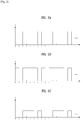
- FIG. 2 illustrates a method for applying DC to the earphone of the portable device according to an embodiment.
- the portable device may apply DC to the earphone through a battery.
- the portable device may change at least one of the generation period, duration, and magnitude of the current supplied to the earphone.
- the vertical axis may represent the magnitude of DC and the horizontal axis may represent time.
- the unit of the vertical axis may be a current unit mA
- the unit of the horizontal axis may be a time unit, msec or a unit time.
- the portable device may generate a DC pattern by applying or blocking DC to the earphone over time, and the coils of the earphone may generate an electromagnetic pattern according to the DC pattern.
- the portable device may generate a first electromagnetic pattern by applying a first DC pattern to the earphone.
- the portable device may repeatedly generate the first DC pattern every 8 unit times.
- the portable device may apply DC to the earphone from unit time 0 to unit time 1, from unit time 2 to unit time 5, and from unit time 6 to unit time 7, while the portable device may block DC to the earphone from unit time 1 to unit time 2, from unit time 5 to unit time 6, and from unit time 7 to unit time 8.
- the portable device may generate the first DC pattern by repeating the DC applying method used for unit time 0 to unit time 8 after unit time 8.
- the generation period of the first DC pattern is 8 unit times and the duration of DC is 1 or 3 unit times in the first DC pattern.
- FIG. 2b illustrates a method for generating a second DC pattern that is different from the first DC pattern in terms of the generation period and duration of DC.
- the portable device may generate a second electromagnetic pattern by applying the second DC pattern to the earphone.
- the portable device may repeatedly generate the second DC pattern every 7 unit times.
- the portable device may apply DC to the earphone from unit time 0 to unit time 1 and from unit time 2 to unit time 6, while the portable device may block DC to the earphone from unit time 1 to unit time 2 and from unit time 6 to unit time 7.
- the portable device may generate the second DC pattern by repeating the DC applying method used for unit time 0 to unit time 7 after unit time 7.
- the generation period of the first DC pattern is 7 unit times and the duration of DC is 1 or 4 unit times in the second DC pattern.
- FIG. 2c illustrates a method for generating a third DC pattern that differs partially from the first DC pattern in terms of the magnitude of DC.
- the portable device may generate a third electromagnetic pattern by applying the third DC pattern to the earphone.
- the portable device may repeatedly generate the third DC pattern every 8 unit times.
- the portable device may apply DC to the earphone from unit time 0 to unit time 2, from unit time 2 to unit time 5, and from unit time 6 to unit time 7.
- the portable device may reduce the magnitude of DC applied from unit time 2 to unit time 5 and from unit time 6 to unit time 7 to a half of the magnitude of DC in the first DC pattern. In this manner, the third DC pattern different from the first DC pattern may be generated.
- the portable device may block DC to the earphone from unit time 1 to unit time 2, from unit time 5 to unit time 6, and from unit time 7 to unit time 8.
- the portable device may generate the third DC pattern by repeating the DC applying method used from unit time 0 to unit time 8 after unit time 8.
- the third DC pattern may partially have a half of the magnitude of DC in the first DC pattern.
- the portable device may generate a different DC pattern by changing at least one of the generation period, duration, and magnitude of DC applied to the earphone. Further, the portable device may generate a different electromagnetic pattern by applying a different DC pattern to a coil of the earphone. If a plurality of portable devices are present, each portable device may provide its ID to an external device by generating a different electromagnetic pattern. The external device may acquire the IDs of the portable devices from different electromagnetic patterns and thus may transmit data to a desired portable device.
- FIG. 3 illustrates a method for recognizing an electromagnetic pattern in a display device and a magnetic field according to an embodiment.
- the portable device may generate an electromagnetic pattern corresponding to its ID for a display device through the earphone connected to the portable device.
- the display device may acquire the ID of the portable device by sensing the electromagnetic pattern generated from the earphone connected to the portable device. Further, the display device may sense the position of the earphone on the display device by sensing a magnetic field of a magnet of the earphone connected to the portable device.
- FIG. 3b illustrates a magnetic field sensed by the display device.
- the earphone 11 connected to the portable device may include a unit 12 and the cable 13.
- the unit 12 of the earphone 11 may include a magnet 31 and a coil 32.
- the portable device may generate an electromagnetic pattern by applying DC to the coil 32 through the cable 13.
- the electromagnetic pattern may correspond to the ID of the portable device.
- the display device 30 may sense the position of the earphone 11 by sensing a magnetic field generated from the magnet 31 of the earphone 11 in the disclosure. The moment the unit 12 of the earphone 11 is brought into contact with a display unit 33, the display device 30 may sense that the unit 12 of the earphone 11 is within a detection area of the display unit 33.
- the display device 30 may acquire the ID of the portable device by sensing an electromagnetic pattern generated from the coil 32 of the earphone 11.
- the display device 30 may include the display unit 33, an electromagnetic pattern sensing unit 34 for sensing the electromagnetic pattern of the portable device, and a sensor unit 35 for sensing the magnetic field of the magnet 31 of the earphone 11.
- the display device 30 may set the sensing coverage of the electromagnetic pattern sensing unit 34 to the entire area of the display unit 33 in order to sense the electromagnetic pattern of the earphone 11 within a detection area of the display unit 33. In another embodiment, the display device 30 may set the sensing coverage of the electromagnetic pattern sensing unit 34 to a partial area of the display unit 33. In addition, the display device 30 may set the sensing coverage of the sensor unit 35 in correspondence with the display unit 33 in order to sense the position of the earphone 11 on the display unit 33. The display device 30 may sense the position of the earphone 11 based on the sensing coverage of the sensor unit 35 corresponding to the area of the display unit 33. The display device 30 may transmit data corresponding to a Graphic User Interface (GUI) displayed at the sensed position of the earphone 11 to the portable device. Data transmitted by the display device will be described later with reference to FIG. 5 .
- GUI Graphic User Interface
- the electromagnetic pattern sensing unit 34 and the sensor unit 35 may be incorporated into a single magnetic sensor unit. If a geomagnetic sensor is included in the display device 30, the display device 30 may sense a magnetic field generated the magnet 31 and an electromagnetic pattern generated from the coil 32 using the geomagnetic sensor.
- FIG. 3b is a graph illustrating changes of a magnetic field sensed by the display device according to an embodiment.
- the vertical axis represents the strength of the magnetic field and the horizontal axis represents time.
- the magnetic field sensed by the display device may get stronger during time period t1.
- the display device may sense a magnetic field generated from a magnet of the earphone. As the distance between the display device and the earphone gets narrower, the display device may sense an increasing strength of the magnetic field.
- the strength of the magnetic field sensed by the display device may be kept constant during time period t2. If the earphone connected to the portable device is apart from the display device by a constant distance, the display device may sense that the strength of the magnetic field is kept constant. For example, when the earphone contacts the display device, the earphone cannot be closer to the display device. Therefore, the magnetic field sensed by the display device has a constant strength.
- the strength of the magnetic field sensed by the display device may increase and decrease alternately during time period t3.
- the display device may sense the electromagnetic pattern.
- the strength of the magnetic field sensed by the display device may increase or decrease according to the direction or magnitude of current applied by the portable device.
- the strength of the magnetic field sensed by the display device may increase.
- the portable device applies a reverse current or decreases a current magnitude the strength of the magnetic field sensed by the display device may decrease.
- the portable device applies current in a constant direction or at a constant magnitude level the strength of the magnetic field sensed by the display device may be kept constant.
- the display device may detect an electromagnetic pattern generated from the earphone by sensing the afore-described increasing and decreasing strength of a magnetic field.
- FIG. 4 illustrates a method for operating the earphone according to an embodiment.
- the portable device 10 may be connected to the earphone 11.
- the portable device 10 may control the output of the earphone 11 adaptively according to the operation state of the earphone 11. If a user wears a unit of the earphone 11 in an ear, the portable device 10 may output sound through the unit of the earphone 11. If a unit of the earphone 11 is removed from the user's ear, the portable device 10 may generate an electromagnetic pattern through the unit of the earphone apart from the ear.
- the portable device 10 may be connected to the earphone 11.
- the portable device 10 may sense whether the units 12-1 and 12-2 of the earphone 11 are worn in the ears 40 of a user or removed from the ears 40 of the user.
- the portable device 10 may sense that the left unit 12-1 of the earphone 11 is worn in an ear 40 of the user by means of the sensor unit.
- the portable device 10 may further sense that the user has removed the right unit 12-2 of the earphone 11 from the ear 40 with his or her hand, by means of the sensor unit.
- the portable device 10 may output sound through the left unit 12-1 worn in the ear 40 of the user by applying AC to the left unit 12-1.
- the portable device 10 may output the left sound of stereo sound through the left unit 12-1.
- the portable device 10 may output both the left and right sounds of the stereo sound in combination through the left unit 12-1. Even though the user wears only the left unit 12-1, the user can hear the left and right sounds of the stereo sound.
- the portable device 10 may generate an electromagnetic pattern by applying DC to the right unit 12-2 removed from the ear 40 of the user.
- the portable device 10 may generate an electromagnetic pattern corresponding to the ID of the portable device 10 through the right unit 12-2.
- the portable device 10 may transmit the ID of the portable device 10 to an external device 42 by the electromagnetic pattern generated through the right unit 12-2.
- the external device 42 may be another portable device or a display device as described before with reference to FIG. 3a .
- the external device 42 may transmit data in response to the acquired ID of the portable device 10.
- the external device 42 may sense the position of the unit 12-2 of the earphone 11 connected to the portable device 10.
- the external device 42 may transmit data corresponding to a GUI touched by the unit 12-2 of the earphone 11 to the portable device 10 according to the sensed position of the earphone 11. For example, if the earphone 11 touches a GUI 43-1 of a music file displayed on the external device 42, the external device 42 may transmit the music file corresponding to the GUI 43-1 to the portable device 10.
- the external device 42 may use streaming in transmitting the music file to the portable device 10.
- the external device 42 may display the graphic effect that the GUI 43-1 of the music file transmitted to the portable device 10 disappears into the touched area of the unit 12-2 of the earphone 11.
- the portable device 10 may receive the data from the external device 42.
- the portable device 10 may display a GUI of the received data. For example, upon receipt of the music file from the external device 42, the portable device 10 may indicate data reception by displaying a GUI 43-2 of the received music file. Or the portable device 10 may display the GUI 43-2 of the received music file on a connector connecting between the portable device 10 and the earphone 11. The portable device 10 may display the graphic effect that the GUI 43-2 of the received music file is being input to the portable device 10 through the earphone connector.
- the portable device 10 may output the data received from the external device 42. For example, if the received data is visual data, the portable device 10 may display the received visual data on a display unit. If the received data is audible data, the portable device 10 may output the audible data through a speaker or the connected earphone. If the received data is tactile data, the portable device 10 may generate a tactile feedback for the received tactile data by means of a tactile feedback unit.
- FIG. 5 illustrates a method for determining transmission data in correspondence with the position of the earphone according to an embodiment.
- a display device may display a GUI.
- the display device may determine transmission data in correspondence with the sensed position of the earphone on the displayed GUI.
- a display device 50 may display GUIs.
- the display device 50 may display the GUIs along with digital content 51 such as a movie or an animation.
- digital content 51 such as a movie or an animation.
- the display device 50 may display GUIs 52 and 53 corresponding to the plurality of language options.
- the display device 50 may provide the first GUI 52 corresponding to Korean and the second GUI 53 corresponding to English as language options for images of the digital content 51.
- the display device 50 may detect a first earphone 54 of a first external device at a displayed position of the first GUI 52.
- the first external device may be the afore-described portable device.
- the display device 50 may sense a first electromagnetic pattern received through the first earphone.
- the display device 50 may acquire the ID of the first external device from the sensed first electromagnetic pattern.
- the display device 50 may determine data to be transmitted to the first external device in correspondence with the GUI displayed at the detected position of the first earphone 54. That is, the display device 50 may transmit Korean data of the digital content 51 to the first external device in correspondence with the first GUI 52 displayed at the detected position of the first earphone 54.
- the display device 50 may adopt streaming in transmitting the Korean data to the first external device. If the digital content 51 does not include the Korean data, the display device 50 may translate data of another language into Korean data and transmit the Korean data. Accordingly, the first external device may output the digital content 51 in a Korean version.
- the display device 50 may detect a second earphone 55 of a second external device at a displayed position of the second GUI 53.
- the second external device may be the afore-described portable device.
- the display device 50 may sense a second electromagnetic pattern received through the second earphone.
- the display device 50 may acquire the ID of the second external device from the sensed second electromagnetic pattern.
- the display device 50 may determine data to be transmitted to the second external device in correspondence with the GUI displayed at the detected position of the second earphone 55. That is, the display device 50 may transmit English data of the digital content 51 to the second external device in correspondence with the second GUI 53 displayed at the detected position of the second earphone 55.
- the display device 50 may adopt streaming in transmitting the English data to the second external device. If the digital content 51 does not include the English data, the display device 50 may translate data of another language into English data and transmit the English data to the second external device. Accordingly, the second external device may receive the English data and output the digital content 51 in an English version.
- the display device 50 may determine the language of data to be transmitted to an external device in correspondence with the detected position of an earphone of an external device. If the display device 50 detects a plurality of earphones, the display device 50 may transmit data in a language corresponding to the detected position of each earphone to a device connected to the earphone. Accordingly, if two users view the digital content 51 on one display device 50, they may view the digital content 51 in different languages.
- FIG. 6 illustrates data transmission between a portable device and a display device according to an embodiment.
- the display device may include a kiosk in the disclosure.
- the display device may take the form of a kiosk to provide guidance on items exhibited in a museum. A user may visit the museum, carrying the portable device 10. To receive guidance on details of exhibited items, the user may touch a display device 61 with the earphone connected to the portable device 10. A method for operating each device in this situation will be described below.
- the portable device 10 may sense removal of the left unit 12-1 of the earphone 11 from an ear of the user.
- the portable device 10 may generate an electromagnetic pattern corresponding to the ID of the portable device 10 by applying DC to the left unit 12-1.
- the display device 61 may display information about an exhibited item 60.
- the display device 61 may detect the left unit 12-1 of the earphone 11 connected to the portable device 10.
- the display device 61 may sense an electromagnetic pattern generated from the left unit 12-1.
- the display device 61 may acquire the ID of the portable device 10 from the sensed electromagnetic pattern.
- the display device 61 may determine data to be transmitted to the portable device 10 in correspondence with a GUI displayed at the detected position of the left unit 12-1 of the earphone 11.
- the display device 61 may transmit the data to the detected ID of the portable device 10.
- the display device 61 may adopt streaming for data transmission.
- the portable device 10 may receive the data from the display device 61 and output the received data.
- the portable device 10 may output the data through the right unit 12-2 of the earphone 11 worn in an ear of the user.
- the user may listen to a description of an exhibited item by touching the display device 61 with one of the units of the earphone worn in the user's ears. Accordingly, the user may listen to the description of the exhibited item using the portable device 10 without the need for using an additional guidance device.
- FIG. 7 is a block diagram of a portable device according to an embodiment.
- the portable device may include a communication unit 101, a sensor unit 102, and a controller 103.
- the communication unit 101 may transmit data to or receive data from an external device by communicating with the external device in conformance to various protocols.
- the communication unit 101 may receive data from the external device by wireless communication.
- the communication unit 101 may receive data from the external device by wireless communication, Wireless Local Area Network (WLAN), Bluetooth, Zigbee, and short-range communication.
- WLAN Wireless Local Area Network
- the communication unit 101 may receive data from a display device in correspondence with the ID of the portable device.
- the portable device may receive the data by streaming.
- the sensor unit 102 may sense whether the earphone connected to the portable device is worn in the ears of the user or removed from the ears of the user.
- the sensor unit 102 may sense whether each of the left and right units of the earphone is apart from an ear of the user by means of a contact sensor included in at least one of the left and right units of the earphone.
- the sensor unit 102 may transmit information indicating the presence or absence of an earphone unit in an ear of the user to the controller 103.
- the controller 103 may receive the information indicating whether an earphone unit has been removed from an ear of the user from the sensor unit 102.
- the controller 103 may apply DC having a pattern to the earphone unit apart from the user's ear. That is, the controller 103 may apply a DC pattern corresponding to the ID of the portable device to the earphone unit removed from the user's ear, as described before with reference to FIG. 2 .
- the controller 103 may generate an electromagnetic pattern corresponding to the ID of the portable device using the coil of the earphone unit.
- the controller 103 may receive data through the communication unit 101.
- the controller 103 may receive data from an external device in correspondence with the ID of the portable device.
- the controller 103 may receive data from a display device through the communication unit 101 in correspondence with the ID of the portable device.
- FIG. 7 is a block diagram according to an embodiment and separately shown blocks are logically distinguished elements of the portable device in FIG. 7 . Therefore, two or more elements of the portable device may be implemented into one or more chips according to the design of the portable device.
- the portable device may further include a display unit, an audio output unit, and a tactile feedback unit. If the portable device receives visual data through the communication unit 101, the portable device may display the visual data on the display unit. If the portable device receives audible data through the communication unit 101, the portable device may output the audible data through the audio output unit. If the portable device receives tactile data through the communication unit 101, the portable device may generate a tactile feedback corresponding to the tactile data through the tactile feedback unit.
- FIG. 8 is a block diagram of a display device according to an embodiment.
- the display device may include a communication unit 201, a sensor unit 202, a display unit 203, an electromagnetic pattern sensing unit 204, and a controller 205.
- the communication unit 201 may transmit data to or receive data from an external device by communicating with the external device in conformance to various protocols.
- the communication unit 201 may receive data from the external device by wireless communication.
- the communication unit 201 may receive data from the external device by wireless communication, WLAN, Bluetooth, Zigbee, and short-range communication.
- the communication unit 201 may transmit data to a portable device in correspondence with the ID of the portable device acquired from an electromagnetic pattern.
- the display device may transmit the data by streaming.
- the sensor unit 202 may sense the position of a unit of an earphone connected to the external device on the display unit 203 by means of a magnetic sensor.
- the sensor unit 202 may sense a magnetic field of a magnet included in the earphone unit.
- the sensor unit 202 may use a geomagnetic sensor to sense the magnetic field of the magnet included in the earphone unit.
- the sensor unit 202 may provide information about the sensed magnetic field of the earphone to the controller 205 and the controller 205 may detect the position of the earphone based on the received information about the magnetic field of the earphone.
- the display unit 203 may display GUIs.
- the earphone of the external device may approach or touch the display unit 203.
- the display unit 203 may include an Organic Light Emitting Diode (OLED), a Liquid Crystal Display (LCD), an electronic ink, and a flexible display.
- OLED Organic Light Emitting Diode
- LCD Liquid Crystal Display
- the controller 205 may sense the position of the earphone connected to the external device on the display unit 203 by means of the sensor unit 202 and the display unit 203 and may detect a GUI displayed at the sensed position of the earphone. Thus, the controller 205 may determine data to be transmitted to the external device based on the GUI displayed at the position of the earphone.
- the electromagnetic pattern sensing unit 204 may sense an electromagnetic pattern generated from the coil of the unit of the earphone connected to the external device.
- the electromagnetic pattern sensing unit 204 may use a geomagnetic sensor in order to sense the electromagnetic pattern of the coil included in the earphone unit.
- the electromagnetic pattern sensing unit 204 may provide information about the sensed electromagnetic pattern to the controller 205 and the controller 205 may acquire the ID of the external device based on the received information about the electromagnetic pattern.
- the electromagnetic pattern sensing unit 204 may be incorporated into the afore-described sensor unit 202 in the display device.
- the controller 205 may display digital content and GUIs on the display unit 203.
- the controller 205 may also sense the position of the earphone approaching the display unit 203 of the display device by means of the sensor unit 202.
- the earphone is connected to the external device.
- the controller 205 may determine data to be transmitted to the external device based on a displayed GUI and the position of the earphone.
- the controller 205 may sense the electromagnetic pattern generated from the earphone by means of the electromagnetic pattern sensing unit 204.
- the controller 205 may acquire the ID of the external device from the sensed electromagnetic pattern.
- the controller 205 may transmit the determined data to the ID of the external device by means of the communication unit 201.
- FIG. 8 is a block diagram according to an embodiment and separately shown blocks are logically distinguished elements of the display device in FIG. 8 . Therefore, two or more elements of the display device may be implemented into one or more chips according to the design of the display device.
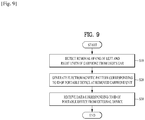
- FIG. 9 is a flowchart illustrating a method for controlling the portable device according to an embodiment.
- the portable device may detect removal of one of the left and right units of the earphone from an ear of the user (S10). As described before with reference to FIG. 4 , the earphone may sense removal of the earphone unit from the user's ear using at least one of a contact sensor, an infrared sensor, and a proximity sensor. The earphone may provide the sensed result to the sensor unit of the portable device through the cable. The portable device may determine whether the unit of the earphone connected to the portable device has been removed from the user's ear.
- the portable device may generate an electromagnetic pattern corresponding to the ID of the portable device at the earphone unit removed from the user's ear by means of the controller (S20).
- the portable device may apply DC to the earphone.
- the portable device may apply DC to the removed earphone unit through the cable of the earphone and the coil of the removed earphone unit may generate an electromagnetic field by the DC.
- the portable device may apply the DC in a pattern.
- the portable device may apply a DC pattern to the earphone so that the removed earphone unit may generate an electromagnetic pattern.
- the portable device may apply the DC pattern in correspondence with the ID of the portable device and thus the removed earphone unit may generate an electromagnetic pattern.
- the portable device may provide its ID to an external device by generating the electromagnetic pattern at the removed unit of the earphone.
- the portable device may output sound by applying AC to a unit of the earphone worn in an ear of the user.
- the portable device may receive data from the external device through the communication unit in correspondence with the ID of the portable device (S30). As described with reference to FIGS. 4 , 5 and 6 , upon receipt of the ID of the portable device by the electromagnetic pattern, the external device may transmit data in correspondence with the ID of the portable device. The portable device may receive the data from the external device and output the received data. If the received data is audible data, the portable device may output the audible data to the earphone unit worn in the user's ear.
- the portable device may output the received audible data to the worn earphone unit by applying AC to the worn earphone unit. If the received audible data is stereo sound, the portable device may output the left and right sounds of the stereo sound in combination to the worn earphone unit. Thus, the portable device may output both the left and right sounds of the stereo sound just through one earphone unit.
- FIG. 10 is a flowchart illustrating a method for controlling a display device according to an embodiment.
- the display device may display GUIs on the display unit (S110). As described before with reference to FIG. 5 , the display device may display digital content on the display unit and may display GUIs according to the digital content on the display unit. The display device may indicate to the user that data can be transmitted and received through an earphone by a displayed GUI.
- the display device may sense an earphone approaching the display unit by means of the sensor unit (S120). As described before with reference to FIG. 3 , when an earphone connected to an external device approaches the display unit, the display device may sense a magnetic field generated from a magnet included in the earphone. The display device may detect the position of the earphone on the display unit by analyzing the sensed magnetic field. The display device may use a geomagnetic sensor to sense the magnetic field of the earphone.
- the display device may sense an electromagnetic pattern of the earphone within a detection area of the display unit by means of the electromagnetic pattern sensing unit (S130). As described before with reference to FIG. 3 , the display device may sense the electromagnetic pattern of the earphone by means of the electromagnetic pattern sensing unit. The display device may sense an electromagnetic field generated from the earphone and a changing pattern of the electromagnetic field, thereby sensing the electromagnetic pattern. Since the electromagnetic pattern is generated in correspondence with the ID of the external device connected to the earphone, the display device may sense a different electromagnetic pattern from an earphone connected to a different external device.
- the display device may acquire the ID of the external device connected to the earphone from the sensed electromagnetic pattern using the controller (S140). As described with reference to FIG. 3 , the display device may acquire the ID of the external device, corresponding to the sensed electromagnetic pattern. In an embodiment, the display device may pre-store the IDs of external devices corresponding to electromagnetic patterns. In another embodiment, the display device may acquire the ID of an external device from a sensed electromagnetic pattern according to a rule of translating an electromagnetic pattern to numbers or characters.
- the display device may transmit data to the external device identified by the acquired ID through the communication unit (S150). As described before with reference to FIGS. 4 and 5 , the display device may determine transmission data in correspondence with the sensed position of the earphone and a GUI displayed at the sensed position of the earphone on the display unit. The display device may transmit the determined transmission data to the acquired ID of the external device. The display device may adopt streaming in transmitting the determined transmission data.
- the portable device and the display device may exchange data with each other through an earphone. That is, the portable device and the display device may be connected to each other and transmit to or receive data from each other just by bringing the earphone connected to the portable device toward the display device, without the need for an additional connection setup between the two devices.
- a portable device can transmit its ID to an external device through an earphone.
- the present invention is totally or partially applicable to electronic devices.
Landscapes
- Engineering & Computer Science (AREA)
- Physics & Mathematics (AREA)
- Theoretical Computer Science (AREA)
- General Engineering & Computer Science (AREA)
- Human Computer Interaction (AREA)
- General Physics & Mathematics (AREA)
- Signal Processing (AREA)
- Acoustics & Sound (AREA)
- Electromagnetism (AREA)
- Computer Networks & Wireless Communication (AREA)
- Telephone Function (AREA)
Claims (15)
- Tragbares Gerät, das mit einem Ohrhörer verbunden ist, der eine Spule aufweist, wobei das tragbare Gerät umfasst:eine Sensoreinheit (102), die dazu konfiguriert ist zu erfassen, ob der Ohrhörer von einem Benutzer getragen wird,eine Kommunikationseinheit (101), die dazu eingerichtet ist, Daten an zumindest ein externes Gerät zu senden und Daten von diesem zu empfangen, undeine Steuereinheit (103), die konfiguriert ist zum:Erfassen eines Entfernens eines ersten Teils des Ohrhörers von einem Ohr des Benutzers, wobei das erste Teil ein linker oder rechter Teil des Ohrhörers ist,Erzeugen eines elektromagnetischen Musters entsprechend einem Identifikator (ID) des tragbaren Geräts an dem ersten Teil des Ohrhörers, um den ID zu einem bestimmten externen Gerät zu übertragen, undEmpfangen von Daten entsprechend dem ID des tragbaren Geräts von dem bestimmten externen Gerät durch die Kommunikationseinheit, wobei das bestimmte externe Gerät den ID des tragbaren Geräts identifiziert.
- Tragbares Gerät nach Anspruch 1, bei dem die Steuereinheit dazu konfiguriert ist, das elektromagnetische Muster zu erzeugen durch Anlegen eines Gleichstroms (DC) an die Spule des Ohrhörers.
- Tragbares Gerät nach Anspruch 2, bei dem die Steuereinheit dazu konfiguriert ist, das elektromagnetische Muster zu erzeugen durch Ändern einer Stärke und/oder einer Aufbringungszeit des DC.
- Tragbares Gerät nach einem der Ansprüche 1 bis 3, bei dem die Steuereinheit ferner dazu konfiguriert ist, die von dem externen Gerät empfangenen Daten auszugeben,
wobei dann, wenn die empfangenen Daten hörbare Daten sind, die Steuereinheit dazu konfiguriert ist, sowohl linke und rechte Schallschwingungen der hörbaren Daten durch ein zweites Teil auszugeben, welches das andere der linken und rechten Teile des Ohrhörers ist, welches in einem Ohr des Benutzers getragen wird. - Tragbares Gerät nach einem der Ansprüche 1 bis 3, ferner umfassend eine Anzeigeeinheit (203), die zum Anzeigen einer grafischen Benutzerschnittstelle (GUI) konfiguriert ist,
wobei die Steuereinheit ferner dazu konfiguriert ist, die von dem externen Gerät empfangenen Daten auszugeben,
wobei dann, wenn die empfangenen Daten bildgebende Daten sind, die Steuereinheit dazu konfiguriert ist, die bildgebenden Daten über die Anzeigeeinheit auszugeben. - Tragbares Gerät nach einem der Ansprüche 1 bis 3, ferner umfassend eine taktile Rückmeldungseinheit, die zum Ausgeben einer taktilen Rückmeldung konfiguriert ist,
wobei die Steuereinheit ferner dazu konfiguriert ist, die von dem externen Gerät empfangenen Daten auszugeben,
wobei dann, wenn die empfangenen Daten taktile Daten sind, die Steuereinheit dazu konfiguriert ist, die taktilen Daten über die taktile Rückmeldungseinheit auszugeben. - Tragbares Gerät nach einem der Ansprüche 1 bis 6, ferner umfassend:einen Verbinder, der dazu konfiguriert ist, ein Einstecken des Ohrhörers zu erlauben, undeine Anzeigeeinheit, die zum Anzeigen einer GUI konfiguriert ist,wobei die Steuereinheit ferner dazu konfiguriert ist, einen Empfangszustand der empfangenen Daten als eine GUI in Übereinstimmung mit einer Stellung des Verbinders anzuzeigen.
- Anzeigevorrichtung, mit:einer Anzeigeeinheit (203), die zum Anzeigen einer grafischen Benutzerschnittstelle (GUI) konfiguriert ist,einer elektromagnetisches Muster-Erfassungseinheit (204), die zum Erfassen eines elektromagnetischen Musters konfiguriert ist,einer Sensoreinheit (202), die zum Erfassen eines Ohrhörers innerhalb eines Erfassungsbereichs der Anzeigeeinheit konfiguriert ist,einer Kommunikationseinheit (201), die dazu konfiguriert ist, Daten an wenigstens ein externes Gerät zu übertragen und Daten von diesem zu empfangen, undeiner Steuereinheit (205), die konfiguriert ist zum:Anzeigen der GUI auf der Anzeigeeinheit,Erfassen des Ohrhörers innerhalb eines Erfassungsbereichs der Anzeigeeinheit mittels der Sensoreinheit,Erfassen eines elektromagnetischen Musters des Ohrhörers innerhalb eines Erfassungsbereichs der Anzeigeeinheit mittels der elektromagnetisches Muster-Erfassungseinheit,Erlangen eines Identifikators (ID) eines bestimmten externen Geräts, das mit dem Ohrhörer verbunden ist, aus dem erfassten elektromagnetischen Muster, undÜbertragen von Daten an das bestimmte externe Gerät, welches mit dem erlangten ID des bestimmten externen Geräts identifiziert wurde, durch die Kommunikationseinheit.
- Anzeigevorrichtung nach Anspruch 8, bei der die Steuereinheit ferner dazu konfiguriert ist, eine Position des Ohrhörers auf der Anzeigeeinheit mittels der Sensoreinheit zu erfassen.
- Anzeigevorrichtung nach Anspruch 9, bei der die Steuereinheit dazu konfiguriert ist, die Position des Ohrhörers durch Erfassen eines Magnetfelds eines in dem Ohrhörer enthaltenen Magnets mittels der Sensoreinheit festzustellen.
- Anzeigevorrichtung nach einem der Ansprüche 9 bis 10, bei der die Steuereinheit dazu konfiguriert ist, der festgestellten Position des Ohrhörers entsprechende Daten an das externe Gerät zu übertragen,
wobei die Steuereinheit dazu konfiguriert ist, Daten an das externe Gerät zu übertragen, die der GUI angezeigt an der festgestellten Position des Ohrhörers entsprechen. - Anzeigevorrichtung nach einem der Ansprüche 9 bis 10, wobei dann, wenn die Daten hörbare Daten sind, die Steuereinheit ferner dazu konfiguriert ist, die hörbaren Daten in eine der festgestellten Position des Ohrhörers entsprechende Sprache zu übersetzen und die übersetzten hörbaren Daten an das externe Gerät zu übertragen.
- Anzeigevorrichtung nach einem der Ansprüche 8 bis 12, bei der die elektromagnetisches Muster-Erfassungseinheit dazu konfiguriert ist, das elektromagnetische Muster des Ohrhörers innerhalb eines Erfassungsbereichs der Anzeigeeinheit unter Benutzung eines geomagnetischen Sensors zu erfassen.
- Anzeigevorrichtung nach einem der Ansprüche 8 bis 12, wobei die Steuereinheit dazu konfiguriert ist festzustellen, dass der Ohrhörer sich innerhalb eines Erfassungsbereichs der Anzeigeeinheit befindet, wenn der Ohrhörer die Anzeigeeinheit berührt.
- Verfahren zum Steuern einer Anzeigevorrichtung, wobei das Verfahren umfasst:Anzeigen einer grafischen Benutzerschnittstelle (GUI) auf einer Anzeigeeinheit,Erfassen eines Ohrhörers innerhalb eines Erfassungsbereichs der Anzeigeeinheit mittels einer Sensoreinheit,Erfassen eines elektromagnetischen Musters des Ohrhörers innerhalb eines Erfassungsbereichs der Anzeigeeinheit mittels einer elektromagnetisches Muster-Erfassungseinheit,Erlangen eines Identifikators (ID) eines mit dem Ohrhörer verbundenen externen Geräts aus dem erfassten elektromagnetischen Muster unter Benutzung einer Steuereinheit, undÜbertragen von Daten an das externe Gerät, welches durch den erlangten ID des externen Geräts identifiziert wurde, mittels einer Kommunikationseinheit.
Applications Claiming Priority (4)
| Application Number | Priority Date | Filing Date | Title |
|---|---|---|---|
| US201361751262P | 2013-01-11 | 2013-01-11 | |
| KR1020130017042A KR102052372B1 (ko) | 2013-01-11 | 2013-02-18 | 이어폰을 이용한 데이터 송수신 디바이스 및 그 제어 방법 |
| US13/856,093 US9030409B2 (en) | 2013-01-11 | 2013-04-03 | Device for transmitting and receiving data using earphone and method for controlling the same |
| PCT/KR2013/003037 WO2014109434A1 (en) | 2013-01-11 | 2013-04-11 | Device for transmitting and receiving data using earphone and method for controlling the same |
Publications (3)
| Publication Number | Publication Date |
|---|---|
| EP2944153A1 EP2944153A1 (de) | 2015-11-18 |
| EP2944153A4 EP2944153A4 (de) | 2016-09-21 |
| EP2944153B1 true EP2944153B1 (de) | 2018-01-10 |
Family
ID=51738625
Family Applications (1)
| Application Number | Title | Priority Date | Filing Date |
|---|---|---|---|
| EP13870419.2A Active EP2944153B1 (de) | 2013-01-11 | 2013-04-11 | Vorrichtung zum übertragen und empfangen von daten mithilfe von ohrhörern und verfahren zur steuerung davon |
Country Status (5)
| Country | Link |
|---|---|
| US (1) | US9030409B2 (de) |
| EP (1) | EP2944153B1 (de) |
| KR (1) | KR102052372B1 (de) |
| CN (1) | CN104919887B (de) |
| WO (1) | WO2014109434A1 (de) |
Families Citing this family (7)
| Publication number | Priority date | Publication date | Assignee | Title |
|---|---|---|---|---|
| US9672208B2 (en) * | 2014-02-28 | 2017-06-06 | Bose Corporation | Automatic selection of language for voice interface |
| KR101720223B1 (ko) * | 2015-12-28 | 2017-03-27 | 한국정보통신주식회사 | 마그네틱 보안 전송을 지원하는 젠더 |
| TWI657702B (zh) * | 2016-02-04 | 2019-04-21 | 美律實業股份有限公司 | 耳機裝置 |
| WO2020087749A1 (zh) * | 2018-10-29 | 2020-05-07 | 歌尔股份有限公司 | 耳机的交互控制方法、装置,耳机和存储介质 |
| KR102669114B1 (ko) * | 2018-12-17 | 2024-05-28 | 삼성전자주식회사 | Em 신호를 발생시킨 외부 전자 장치에 따라 오디오 신호의 경로를 변경하는 전자 장치 및 방법 |
| CN112689051B (zh) * | 2019-10-18 | 2022-05-20 | 北京小米移动软件有限公司 | 音频播放控制方法、装置、移动终端及存储介质 |
| CN112954418B (zh) * | 2021-02-06 | 2022-05-10 | 读书郎教育科技有限公司 | 一种控制平板播放视频的装置及方法 |
Family Cites Families (17)
| Publication number | Priority date | Publication date | Assignee | Title |
|---|---|---|---|---|
| US6772331B1 (en) | 1999-05-21 | 2004-08-03 | International Business Machines Corporation | Method and apparatus for exclusively pairing wireless devices |
| US20030185400A1 (en) * | 2002-03-29 | 2003-10-02 | Hitachi, Ltd. | Sound processing unit, sound processing system, audio output unit and display device |
| JP4228069B2 (ja) | 2002-12-16 | 2009-02-25 | 独立行政法人産業技術総合研究所 | 音声情報支援システム |
| US7577249B2 (en) | 2003-01-06 | 2009-08-18 | Gn Netcom, Inc. | Wireless remote controlled handset lifter system using magnetically coupled ring detection |
| US20040136552A1 (en) * | 2003-01-10 | 2004-07-15 | Rudolf Bendixen | Information handling system earphone storage method and system |
| US7925214B2 (en) * | 2005-12-16 | 2011-04-12 | Sony Ericsson Mobile Communications Ab | Distributed bluetooth system |
| US8193769B2 (en) * | 2007-10-18 | 2012-06-05 | Powermat Technologies, Ltd | Inductively chargeable audio devices |
| US20090128513A1 (en) * | 2007-11-20 | 2009-05-21 | Samsung Electronics Co., Ltd | Device identification method and apparatus, device information provision method and apparatus, and computer-readable recording mediums having recorded thereon programs for executing the device identification method and the device information provision method |
| US8180078B2 (en) * | 2007-12-13 | 2012-05-15 | At&T Intellectual Property I, Lp | Systems and methods employing multiple individual wireless earbuds for a common audio source |
| US20110163944A1 (en) | 2010-01-05 | 2011-07-07 | Apple Inc. | Intuitive, gesture-based communications with physics metaphors |
| US8789131B2 (en) * | 2010-05-14 | 2014-07-22 | Lg Electronics Inc. | Electronic device and method of sharing contents thereof with other devices |
| KR101690232B1 (ko) * | 2010-05-28 | 2016-12-27 | 엘지전자 주식회사 | 전자 기기 및 전자 기기의 제어 방법 |
| US20120114154A1 (en) * | 2010-11-05 | 2012-05-10 | Sony Ericsson Mobile Communications Ab | Using accelerometers for left right detection of headset earpieces |
| KR101142906B1 (ko) | 2010-11-12 | 2012-05-10 | 오영호 | 터치스크린의 신호입력 기능을 갖는 이어폰 |
| US9030422B2 (en) * | 2011-02-15 | 2015-05-12 | Lg Electronics Inc. | Method of transmitting and receiving data and display device using the same |
| US9326058B2 (en) * | 2012-09-26 | 2016-04-26 | Sony Corporation | Control method of mobile terminal apparatus |
| KR101498087B1 (ko) * | 2013-02-21 | 2015-03-03 | 엘지전자 주식회사 | 블루투스 헤드셋 |
-
2013
- 2013-02-18 KR KR1020130017042A patent/KR102052372B1/ko not_active Expired - Fee Related
- 2013-04-03 US US13/856,093 patent/US9030409B2/en active Active
- 2013-04-11 CN CN201380070163.0A patent/CN104919887B/zh active Active
- 2013-04-11 WO PCT/KR2013/003037 patent/WO2014109434A1/en not_active Ceased
- 2013-04-11 EP EP13870419.2A patent/EP2944153B1/de active Active
Non-Patent Citations (1)
| Title |
|---|
| None * |
Also Published As
| Publication number | Publication date |
|---|---|
| CN104919887A (zh) | 2015-09-16 |
| KR102052372B1 (ko) | 2019-12-05 |
| KR20140091425A (ko) | 2014-07-21 |
| WO2014109434A1 (en) | 2014-07-17 |
| EP2944153A4 (de) | 2016-09-21 |
| US9030409B2 (en) | 2015-05-12 |
| US20140198026A1 (en) | 2014-07-17 |
| CN104919887B (zh) | 2019-11-29 |
| EP2944153A1 (de) | 2015-11-18 |
Similar Documents
| Publication | Publication Date | Title |
|---|---|---|
| EP2944153B1 (de) | Vorrichtung zum übertragen und empfangen von daten mithilfe von ohrhörern und verfahren zur steuerung davon | |
| US11546410B2 (en) | Device and method for adaptively changing task-performing subjects | |
| CN105103083B (zh) | 智能手表 | |
| CN109284001B (zh) | 执行设备的功能的方法以及用于执行该方法的设备 | |
| US10459677B2 (en) | Coordination of device operation on wireless charging surface | |
| KR102447438B1 (ko) | 알림 장치 및 알림 장치가 물건의 위치를 알려주는 방법 | |
| KR102288726B1 (ko) | 웨어러블 전자 장치, 메인 전자 장치, 시스템 및 그 제어 방법 | |
| US20150020081A1 (en) | Digital device and method for controlling the same | |
| KR102124481B1 (ko) | 포터블 디바이스, 스마트 와치 및 제어 방법 | |
| US20170359456A1 (en) | Communication system comprising head wearable devices | |
| JP2014512590A (ja) | 対話型表示システムにおける視覚ペアリング | |
| WO2016055317A1 (en) | Docking system | |
| CN107106032A (zh) | 控制可穿戴装置的装置和方法 | |
| KR102191345B1 (ko) | 전자 기기의 입력 장치, 방법 및 시스템 | |
| CN107148647A (zh) | 显示装置、控制程序、图像显示系统、信息提供服务器以及信息提供方法 | |
| US10429939B2 (en) | Apparatus for projecting image and method for operating same | |
| JP2021166094A (ja) | ペアリング方法及び位置検出システム | |
| KR102381434B1 (ko) | 무선 충전용 스탠드 및 그것과 연동되는 전자 장치의 동작 방법 | |
| KR102004986B1 (ko) | 어플리케이션 실행 방법 및 시스템, 단말과 그 기록 매체 | |
| WO2022028290A1 (zh) | 基于指向操作的设备之间的交互方法及电子设备 | |
| US20160112988A1 (en) | Method for indicating alarm by portable terminal and accessory in conjunction with each other, and apparatus and application for the same | |
| KR102353498B1 (ko) | 기능 제공 방법 및 그 전자 장치 | |
| KR20210091662A (ko) | 외부 전자 장치를 제어하기 위한 전자 장치 및 그 방법 | |
| KR20140113314A (ko) | 전자 장치에서 제스처를 인식하는 방법 및 장치 | |
| CN104238988B (zh) | 一种信息处理方法及电子设备 |
Legal Events
| Date | Code | Title | Description |
|---|---|---|---|
| PUAI | Public reference made under article 153(3) epc to a published international application that has entered the european phase |
Free format text: ORIGINAL CODE: 0009012 |
|
| 17P | Request for examination filed |
Effective date: 20150623 |
|
| AK | Designated contracting states |
Kind code of ref document: A1 Designated state(s): AL AT BE BG CH CY CZ DE DK EE ES FI FR GB GR HR HU IE IS IT LI LT LU LV MC MK MT NL NO PL PT RO RS SE SI SK SM TR |
|
| AX | Request for extension of the european patent |
Extension state: BA ME |
|
| DAX | Request for extension of the european patent (deleted) | ||
| REG | Reference to a national code |
Ref country code: DE Ref legal event code: R079 Ref document number: 602013031989 Country of ref document: DE Free format text: PREVIOUS MAIN CLASS: H04W0076020000 Ipc: H04R0001100000 |
|
| A4 | Supplementary search report drawn up and despatched |
Effective date: 20160823 |
|
| RIC1 | Information provided on ipc code assigned before grant |
Ipc: G06F 3/046 20060101ALI20160817BHEP Ipc: G06F 3/0488 20130101ALI20160817BHEP Ipc: G06F 3/0487 20130101ALI20160817BHEP Ipc: G06F 3/048 20060101ALI20160817BHEP Ipc: H04R 1/10 20060101AFI20160817BHEP Ipc: G06F 3/01 20060101ALI20160817BHEP Ipc: G06F 3/03 20060101ALI20160817BHEP Ipc: G06F 3/041 20060101ALI20160817BHEP |
|
| GRAP | Despatch of communication of intention to grant a patent |
Free format text: ORIGINAL CODE: EPIDOSNIGR1 |
|
| STAA | Information on the status of an ep patent application or granted ep patent |
Free format text: STATUS: GRANT OF PATENT IS INTENDED |
|
| INTG | Intention to grant announced |
Effective date: 20170801 |
|
| GRAS | Grant fee paid |
Free format text: ORIGINAL CODE: EPIDOSNIGR3 |
|
| GRAA | (expected) grant |
Free format text: ORIGINAL CODE: 0009210 |
|
| STAA | Information on the status of an ep patent application or granted ep patent |
Free format text: STATUS: THE PATENT HAS BEEN GRANTED |
|
| AK | Designated contracting states |
Kind code of ref document: B1 Designated state(s): AL AT BE BG CH CY CZ DE DK EE ES FI FR GB GR HR HU IE IS IT LI LT LU LV MC MK MT NL NO PL PT RO RS SE SI SK SM TR |
|
| REG | Reference to a national code |
Ref country code: CH Ref legal event code: EP Ref country code: AT Ref legal event code: REF Ref document number: 963672 Country of ref document: AT Kind code of ref document: T Effective date: 20180115 |
|
| REG | Reference to a national code |
Ref country code: IE Ref legal event code: FG4D |
|
| REG | Reference to a national code |
Ref country code: DE Ref legal event code: R096 Ref document number: 602013031989 Country of ref document: DE |
|
| REG | Reference to a national code |
Ref country code: FR Ref legal event code: PLFP Year of fee payment: 6 |
|
| REG | Reference to a national code |
Ref country code: NL Ref legal event code: MP Effective date: 20180110 |
|
| REG | Reference to a national code |
Ref country code: AT Ref legal event code: MK05 Ref document number: 963672 Country of ref document: AT Kind code of ref document: T Effective date: 20180110 |
|
| PG25 | Lapsed in a contracting state [announced via postgrant information from national office to epo] |
Ref country code: NL Free format text: LAPSE BECAUSE OF FAILURE TO SUBMIT A TRANSLATION OF THE DESCRIPTION OR TO PAY THE FEE WITHIN THE PRESCRIBED TIME-LIMIT Effective date: 20180110 |
|
| PG25 | Lapsed in a contracting state [announced via postgrant information from national office to epo] |
Ref country code: HR Free format text: LAPSE BECAUSE OF FAILURE TO SUBMIT A TRANSLATION OF THE DESCRIPTION OR TO PAY THE FEE WITHIN THE PRESCRIBED TIME-LIMIT Effective date: 20180110 Ref country code: CY Free format text: LAPSE BECAUSE OF FAILURE TO SUBMIT A TRANSLATION OF THE DESCRIPTION OR TO PAY THE FEE WITHIN THE PRESCRIBED TIME-LIMIT Effective date: 20180110 Ref country code: ES Free format text: LAPSE BECAUSE OF FAILURE TO SUBMIT A TRANSLATION OF THE DESCRIPTION OR TO PAY THE FEE WITHIN THE PRESCRIBED TIME-LIMIT Effective date: 20180110 Ref country code: LT Free format text: LAPSE BECAUSE OF FAILURE TO SUBMIT A TRANSLATION OF THE DESCRIPTION OR TO PAY THE FEE WITHIN THE PRESCRIBED TIME-LIMIT Effective date: 20180110 Ref country code: NO Free format text: LAPSE BECAUSE OF FAILURE TO SUBMIT A TRANSLATION OF THE DESCRIPTION OR TO PAY THE FEE WITHIN THE PRESCRIBED TIME-LIMIT Effective date: 20180410 Ref country code: FI Free format text: LAPSE BECAUSE OF FAILURE TO SUBMIT A TRANSLATION OF THE DESCRIPTION OR TO PAY THE FEE WITHIN THE PRESCRIBED TIME-LIMIT Effective date: 20180110 |
|
| PG25 | Lapsed in a contracting state [announced via postgrant information from national office to epo] |
Ref country code: LV Free format text: LAPSE BECAUSE OF FAILURE TO SUBMIT A TRANSLATION OF THE DESCRIPTION OR TO PAY THE FEE WITHIN THE PRESCRIBED TIME-LIMIT Effective date: 20180110 Ref country code: SE Free format text: LAPSE BECAUSE OF FAILURE TO SUBMIT A TRANSLATION OF THE DESCRIPTION OR TO PAY THE FEE WITHIN THE PRESCRIBED TIME-LIMIT Effective date: 20180110 Ref country code: AT Free format text: LAPSE BECAUSE OF FAILURE TO SUBMIT A TRANSLATION OF THE DESCRIPTION OR TO PAY THE FEE WITHIN THE PRESCRIBED TIME-LIMIT Effective date: 20180110 Ref country code: PL Free format text: LAPSE BECAUSE OF FAILURE TO SUBMIT A TRANSLATION OF THE DESCRIPTION OR TO PAY THE FEE WITHIN THE PRESCRIBED TIME-LIMIT Effective date: 20180110 Ref country code: GR Free format text: LAPSE BECAUSE OF FAILURE TO SUBMIT A TRANSLATION OF THE DESCRIPTION OR TO PAY THE FEE WITHIN THE PRESCRIBED TIME-LIMIT Effective date: 20180411 Ref country code: IS Free format text: LAPSE BECAUSE OF FAILURE TO SUBMIT A TRANSLATION OF THE DESCRIPTION OR TO PAY THE FEE WITHIN THE PRESCRIBED TIME-LIMIT Effective date: 20180510 Ref country code: RS Free format text: LAPSE BECAUSE OF FAILURE TO SUBMIT A TRANSLATION OF THE DESCRIPTION OR TO PAY THE FEE WITHIN THE PRESCRIBED TIME-LIMIT Effective date: 20180110 Ref country code: BG Free format text: LAPSE BECAUSE OF FAILURE TO SUBMIT A TRANSLATION OF THE DESCRIPTION OR TO PAY THE FEE WITHIN THE PRESCRIBED TIME-LIMIT Effective date: 20180410 |
|
| REG | Reference to a national code |
Ref country code: DE Ref legal event code: R097 Ref document number: 602013031989 Country of ref document: DE |
|
| PG25 | Lapsed in a contracting state [announced via postgrant information from national office to epo] |
Ref country code: AL Free format text: LAPSE BECAUSE OF FAILURE TO SUBMIT A TRANSLATION OF THE DESCRIPTION OR TO PAY THE FEE WITHIN THE PRESCRIBED TIME-LIMIT Effective date: 20180110 Ref country code: EE Free format text: LAPSE BECAUSE OF FAILURE TO SUBMIT A TRANSLATION OF THE DESCRIPTION OR TO PAY THE FEE WITHIN THE PRESCRIBED TIME-LIMIT Effective date: 20180110 Ref country code: IT Free format text: LAPSE BECAUSE OF FAILURE TO SUBMIT A TRANSLATION OF THE DESCRIPTION OR TO PAY THE FEE WITHIN THE PRESCRIBED TIME-LIMIT Effective date: 20180110 Ref country code: RO Free format text: LAPSE BECAUSE OF FAILURE TO SUBMIT A TRANSLATION OF THE DESCRIPTION OR TO PAY THE FEE WITHIN THE PRESCRIBED TIME-LIMIT Effective date: 20180110 |
|
| PLBE | No opposition filed within time limit |
Free format text: ORIGINAL CODE: 0009261 |
|
| STAA | Information on the status of an ep patent application or granted ep patent |
Free format text: STATUS: NO OPPOSITION FILED WITHIN TIME LIMIT |
|
| PG25 | Lapsed in a contracting state [announced via postgrant information from national office to epo] |
Ref country code: SM Free format text: LAPSE BECAUSE OF FAILURE TO SUBMIT A TRANSLATION OF THE DESCRIPTION OR TO PAY THE FEE WITHIN THE PRESCRIBED TIME-LIMIT Effective date: 20180110 Ref country code: CZ Free format text: LAPSE BECAUSE OF FAILURE TO SUBMIT A TRANSLATION OF THE DESCRIPTION OR TO PAY THE FEE WITHIN THE PRESCRIBED TIME-LIMIT Effective date: 20180110 Ref country code: MC Free format text: LAPSE BECAUSE OF FAILURE TO SUBMIT A TRANSLATION OF THE DESCRIPTION OR TO PAY THE FEE WITHIN THE PRESCRIBED TIME-LIMIT Effective date: 20180110 Ref country code: DK Free format text: LAPSE BECAUSE OF FAILURE TO SUBMIT A TRANSLATION OF THE DESCRIPTION OR TO PAY THE FEE WITHIN THE PRESCRIBED TIME-LIMIT Effective date: 20180110 Ref country code: SK Free format text: LAPSE BECAUSE OF FAILURE TO SUBMIT A TRANSLATION OF THE DESCRIPTION OR TO PAY THE FEE WITHIN THE PRESCRIBED TIME-LIMIT Effective date: 20180110 |
|
| REG | Reference to a national code |
Ref country code: CH Ref legal event code: PL |
|
| 26N | No opposition filed |
Effective date: 20181011 |
|
| REG | Reference to a national code |
Ref country code: BE Ref legal event code: MM Effective date: 20180430 |
|
| REG | Reference to a national code |
Ref country code: IE Ref legal event code: MM4A |
|
| PG25 | Lapsed in a contracting state [announced via postgrant information from national office to epo] |
Ref country code: LU Free format text: LAPSE BECAUSE OF NON-PAYMENT OF DUE FEES Effective date: 20180411 |
|
| PG25 | Lapsed in a contracting state [announced via postgrant information from national office to epo] |
Ref country code: LI Free format text: LAPSE BECAUSE OF NON-PAYMENT OF DUE FEES Effective date: 20180430 Ref country code: BE Free format text: LAPSE BECAUSE OF NON-PAYMENT OF DUE FEES Effective date: 20180430 Ref country code: CH Free format text: LAPSE BECAUSE OF NON-PAYMENT OF DUE FEES Effective date: 20180430 Ref country code: SI Free format text: LAPSE BECAUSE OF FAILURE TO SUBMIT A TRANSLATION OF THE DESCRIPTION OR TO PAY THE FEE WITHIN THE PRESCRIBED TIME-LIMIT Effective date: 20180110 |
|
| PG25 | Lapsed in a contracting state [announced via postgrant information from national office to epo] |
Ref country code: IE Free format text: LAPSE BECAUSE OF NON-PAYMENT OF DUE FEES Effective date: 20180411 |
|
| PG25 | Lapsed in a contracting state [announced via postgrant information from national office to epo] |
Ref country code: MT Free format text: LAPSE BECAUSE OF NON-PAYMENT OF DUE FEES Effective date: 20180411 |
|
| PG25 | Lapsed in a contracting state [announced via postgrant information from national office to epo] |
Ref country code: TR Free format text: LAPSE BECAUSE OF FAILURE TO SUBMIT A TRANSLATION OF THE DESCRIPTION OR TO PAY THE FEE WITHIN THE PRESCRIBED TIME-LIMIT Effective date: 20180110 |
|
| PG25 | Lapsed in a contracting state [announced via postgrant information from national office to epo] |
Ref country code: PT Free format text: LAPSE BECAUSE OF FAILURE TO SUBMIT A TRANSLATION OF THE DESCRIPTION OR TO PAY THE FEE WITHIN THE PRESCRIBED TIME-LIMIT Effective date: 20180110 |
|
| PG25 | Lapsed in a contracting state [announced via postgrant information from national office to epo] |
Ref country code: HU Free format text: LAPSE BECAUSE OF FAILURE TO SUBMIT A TRANSLATION OF THE DESCRIPTION OR TO PAY THE FEE WITHIN THE PRESCRIBED TIME-LIMIT; INVALID AB INITIO Effective date: 20130411 Ref country code: MK Free format text: LAPSE BECAUSE OF NON-PAYMENT OF DUE FEES Effective date: 20180110 |
|
| PGFP | Annual fee paid to national office [announced via postgrant information from national office to epo] |
Ref country code: FR Payment date: 20230306 Year of fee payment: 11 |
|
| PGFP | Annual fee paid to national office [announced via postgrant information from national office to epo] |
Ref country code: GB Payment date: 20230306 Year of fee payment: 11 |
|
| GBPC | Gb: european patent ceased through non-payment of renewal fee |
Effective date: 20240411 |
|
| PG25 | Lapsed in a contracting state [announced via postgrant information from national office to epo] |
Ref country code: GB Free format text: LAPSE BECAUSE OF NON-PAYMENT OF DUE FEES Effective date: 20240411 |
|
| PG25 | Lapsed in a contracting state [announced via postgrant information from national office to epo] |
Ref country code: FR Free format text: LAPSE BECAUSE OF NON-PAYMENT OF DUE FEES Effective date: 20240430 |
|
| PG25 | Lapsed in a contracting state [announced via postgrant information from national office to epo] |
Ref country code: GB Free format text: LAPSE BECAUSE OF NON-PAYMENT OF DUE FEES Effective date: 20240411 Ref country code: FR Free format text: LAPSE BECAUSE OF NON-PAYMENT OF DUE FEES Effective date: 20240430 |
|
| PGFP | Annual fee paid to national office [announced via postgrant information from national office to epo] |
Ref country code: DE Payment date: 20250305 Year of fee payment: 13 |