EP2943913B1 - Système et procédé de réduction du volume de transmission de données en tomosynthèse - Google Patents
Système et procédé de réduction du volume de transmission de données en tomosynthèse Download PDFInfo
- Publication number
- EP2943913B1 EP2943913B1 EP14737752.7A EP14737752A EP2943913B1 EP 2943913 B1 EP2943913 B1 EP 2943913B1 EP 14737752 A EP14737752 A EP 14737752A EP 2943913 B1 EP2943913 B1 EP 2943913B1
- Authority
- EP
- European Patent Office
- Prior art keywords
- acquisition system
- user computer
- image data
- image acquisition
- subset
- Prior art date
- Legal status (The legal status is an assumption and is not a legal conclusion. Google has not performed a legal analysis and makes no representation as to the accuracy of the status listed.)
- Active
Links
- 238000000034 method Methods 0.000 title claims description 84
- 230000005540 biological transmission Effects 0.000 title description 11
- 210000000481 breast Anatomy 0.000 claims description 65
- 238000012545 processing Methods 0.000 claims description 33
- 230000008569 process Effects 0.000 claims description 16
- 238000009607 mammography Methods 0.000 claims description 13
- 230000005856 abnormality Effects 0.000 claims description 8
- 230000004044 response Effects 0.000 claims description 6
- 238000012552 review Methods 0.000 description 16
- 238000001514 detection method Methods 0.000 description 10
- 238000003384 imaging method Methods 0.000 description 9
- 238000012512 characterization method Methods 0.000 description 7
- 238000004891 communication Methods 0.000 description 7
- 238000010586 diagram Methods 0.000 description 6
- 230000003993 interaction Effects 0.000 description 6
- 208000004434 Calcinosis Diseases 0.000 description 5
- 230000008901 benefit Effects 0.000 description 5
- 230000002308 calcification Effects 0.000 description 5
- 238000013500 data storage Methods 0.000 description 4
- 230000006870 function Effects 0.000 description 4
- 206010006187 Breast cancer Diseases 0.000 description 2
- 208000026310 Breast neoplasm Diseases 0.000 description 2
- 230000006835 compression Effects 0.000 description 2
- 238000007906 compression Methods 0.000 description 2
- 238000003745 diagnosis Methods 0.000 description 2
- 230000007246 mechanism Effects 0.000 description 2
- 238000012216 screening Methods 0.000 description 2
- 230000000007 visual effect Effects 0.000 description 2
- 230000009471 action Effects 0.000 description 1
- 238000004458 analytical method Methods 0.000 description 1
- 230000008878 coupling Effects 0.000 description 1
- 238000010168 coupling process Methods 0.000 description 1
- 238000005859 coupling reaction Methods 0.000 description 1
- 238000013461 design Methods 0.000 description 1
- 238000011161 development Methods 0.000 description 1
- 238000006073 displacement reaction Methods 0.000 description 1
- 238000005516 engineering process Methods 0.000 description 1
- 230000004424 eye movement Effects 0.000 description 1
- 230000003902 lesion Effects 0.000 description 1
- 230000003211 malignant effect Effects 0.000 description 1
- 238000012986 modification Methods 0.000 description 1
- 230000004048 modification Effects 0.000 description 1
- 238000003672 processing method Methods 0.000 description 1
- 238000000638 solvent extraction Methods 0.000 description 1
- 230000001131 transforming effect Effects 0.000 description 1
- 230000007704 transition Effects 0.000 description 1
Images


Classifications
-
- G—PHYSICS
- G06—COMPUTING; CALCULATING OR COUNTING
- G06T—IMAGE DATA PROCESSING OR GENERATION, IN GENERAL
- G06T11/00—2D [Two Dimensional] image generation
- G06T11/003—Reconstruction from projections, e.g. tomography
- G06T11/006—Inverse problem, transformation from projection-space into object-space, e.g. transform methods, back-projection, algebraic methods
-
- A—HUMAN NECESSITIES
- A61—MEDICAL OR VETERINARY SCIENCE; HYGIENE
- A61B—DIAGNOSIS; SURGERY; IDENTIFICATION
- A61B6/00—Apparatus or devices for radiation diagnosis; Apparatus or devices for radiation diagnosis combined with radiation therapy equipment
- A61B6/02—Arrangements for diagnosis sequentially in different planes; Stereoscopic radiation diagnosis
- A61B6/025—Tomosynthesis
-
- A—HUMAN NECESSITIES
- A61—MEDICAL OR VETERINARY SCIENCE; HYGIENE
- A61B—DIAGNOSIS; SURGERY; IDENTIFICATION
- A61B6/00—Apparatus or devices for radiation diagnosis; Apparatus or devices for radiation diagnosis combined with radiation therapy equipment
- A61B6/46—Arrangements for interfacing with the operator or the patient
- A61B6/461—Displaying means of special interest
- A61B6/463—Displaying means of special interest characterised by displaying multiple images or images and diagnostic data on one display
-
- A—HUMAN NECESSITIES
- A61—MEDICAL OR VETERINARY SCIENCE; HYGIENE
- A61B—DIAGNOSIS; SURGERY; IDENTIFICATION
- A61B6/00—Apparatus or devices for radiation diagnosis; Apparatus or devices for radiation diagnosis combined with radiation therapy equipment
- A61B6/50—Apparatus or devices for radiation diagnosis; Apparatus or devices for radiation diagnosis combined with radiation therapy equipment specially adapted for specific body parts; specially adapted for specific clinical applications
- A61B6/502—Apparatus or devices for radiation diagnosis; Apparatus or devices for radiation diagnosis combined with radiation therapy equipment specially adapted for specific body parts; specially adapted for specific clinical applications for diagnosis of breast, i.e. mammography
-
- A—HUMAN NECESSITIES
- A61—MEDICAL OR VETERINARY SCIENCE; HYGIENE
- A61B—DIAGNOSIS; SURGERY; IDENTIFICATION
- A61B6/00—Apparatus or devices for radiation diagnosis; Apparatus or devices for radiation diagnosis combined with radiation therapy equipment
- A61B6/52—Devices using data or image processing specially adapted for radiation diagnosis
- A61B6/5211—Devices using data or image processing specially adapted for radiation diagnosis involving processing of medical diagnostic data
- A61B6/5217—Devices using data or image processing specially adapted for radiation diagnosis involving processing of medical diagnostic data extracting a diagnostic or physiological parameter from medical diagnostic data
-
- A—HUMAN NECESSITIES
- A61—MEDICAL OR VETERINARY SCIENCE; HYGIENE
- A61B—DIAGNOSIS; SURGERY; IDENTIFICATION
- A61B6/00—Apparatus or devices for radiation diagnosis; Apparatus or devices for radiation diagnosis combined with radiation therapy equipment
- A61B6/56—Details of data transmission or power supply, e.g. use of slip rings
- A61B6/563—Details of data transmission or power supply, e.g. use of slip rings involving image data transmission via a network
-
- G—PHYSICS
- G06—COMPUTING; CALCULATING OR COUNTING
- G06T—IMAGE DATA PROCESSING OR GENERATION, IN GENERAL
- G06T15/00—3D [Three Dimensional] image rendering
- G06T15/08—Volume rendering
-
- G—PHYSICS
- G06—COMPUTING; CALCULATING OR COUNTING
- G06T—IMAGE DATA PROCESSING OR GENERATION, IN GENERAL
- G06T7/00—Image analysis
- G06T7/0002—Inspection of images, e.g. flaw detection
- G06T7/0012—Biomedical image inspection
-
- G—PHYSICS
- G16—INFORMATION AND COMMUNICATION TECHNOLOGY [ICT] SPECIALLY ADAPTED FOR SPECIFIC APPLICATION FIELDS
- G16H—HEALTHCARE INFORMATICS, i.e. INFORMATION AND COMMUNICATION TECHNOLOGY [ICT] SPECIALLY ADAPTED FOR THE HANDLING OR PROCESSING OF MEDICAL OR HEALTHCARE DATA
- G16H50/00—ICT specially adapted for medical diagnosis, medical simulation or medical data mining; ICT specially adapted for detecting, monitoring or modelling epidemics or pandemics
- G16H50/20—ICT specially adapted for medical diagnosis, medical simulation or medical data mining; ICT specially adapted for detecting, monitoring or modelling epidemics or pandemics for computer-aided diagnosis, e.g. based on medical expert systems
-
- G—PHYSICS
- G16—INFORMATION AND COMMUNICATION TECHNOLOGY [ICT] SPECIALLY ADAPTED FOR SPECIFIC APPLICATION FIELDS
- G16H—HEALTHCARE INFORMATICS, i.e. INFORMATION AND COMMUNICATION TECHNOLOGY [ICT] SPECIALLY ADAPTED FOR THE HANDLING OR PROCESSING OF MEDICAL OR HEALTHCARE DATA
- G16H50/00—ICT specially adapted for medical diagnosis, medical simulation or medical data mining; ICT specially adapted for detecting, monitoring or modelling epidemics or pandemics
- G16H50/30—ICT specially adapted for medical diagnosis, medical simulation or medical data mining; ICT specially adapted for detecting, monitoring or modelling epidemics or pandemics for calculating health indices; for individual health risk assessment
-
- A—HUMAN NECESSITIES
- A61—MEDICAL OR VETERINARY SCIENCE; HYGIENE
- A61B—DIAGNOSIS; SURGERY; IDENTIFICATION
- A61B6/00—Apparatus or devices for radiation diagnosis; Apparatus or devices for radiation diagnosis combined with radiation therapy equipment
- A61B6/46—Arrangements for interfacing with the operator or the patient
- A61B6/467—Arrangements for interfacing with the operator or the patient characterised by special input means
- A61B6/469—Arrangements for interfacing with the operator or the patient characterised by special input means for selecting a region of interest [ROI]
-
- A—HUMAN NECESSITIES
- A61—MEDICAL OR VETERINARY SCIENCE; HYGIENE
- A61B—DIAGNOSIS; SURGERY; IDENTIFICATION
- A61B6/00—Apparatus or devices for radiation diagnosis; Apparatus or devices for radiation diagnosis combined with radiation therapy equipment
- A61B6/52—Devices using data or image processing specially adapted for radiation diagnosis
- A61B6/5211—Devices using data or image processing specially adapted for radiation diagnosis involving processing of medical diagnostic data
- A61B6/5223—Devices using data or image processing specially adapted for radiation diagnosis involving processing of medical diagnostic data generating planar views from image data, e.g. extracting a coronal view from a 3D image
-
- G—PHYSICS
- G06—COMPUTING; CALCULATING OR COUNTING
- G06T—IMAGE DATA PROCESSING OR GENERATION, IN GENERAL
- G06T2200/00—Indexing scheme for image data processing or generation, in general
- G06T2200/04—Indexing scheme for image data processing or generation, in general involving 3D image data
-
- G—PHYSICS
- G06—COMPUTING; CALCULATING OR COUNTING
- G06T—IMAGE DATA PROCESSING OR GENERATION, IN GENERAL
- G06T2207/00—Indexing scheme for image analysis or image enhancement
- G06T2207/30—Subject of image; Context of image processing
- G06T2207/30004—Biomedical image processing
- G06T2207/30068—Mammography; Breast
-
- G—PHYSICS
- G06—COMPUTING; CALCULATING OR COUNTING
- G06T—IMAGE DATA PROCESSING OR GENERATION, IN GENERAL
- G06T2207/00—Indexing scheme for image analysis or image enhancement
- G06T2207/30—Subject of image; Context of image processing
- G06T2207/30196—Human being; Person
-
- G—PHYSICS
- G06—COMPUTING; CALCULATING OR COUNTING
- G06T—IMAGE DATA PROCESSING OR GENERATION, IN GENERAL
- G06T2210/00—Indexing scheme for image generation or computer graphics
- G06T2210/41—Medical
-
- G—PHYSICS
- G06—COMPUTING; CALCULATING OR COUNTING
- G06T—IMAGE DATA PROCESSING OR GENERATION, IN GENERAL
- G06T2211/00—Image generation
- G06T2211/40—Computed tomography
- G06T2211/436—Limited angle
Definitions
- the invention disclosed herein pertain to breast imaging using tomosynthesis, and more specifically to systems and methods for obtaining, processing, communicating, and navigating a tomosynthesis data set or a subset thereof.
- Mammography has long been used to screen for breast cancer and other abnormalities.
- mammograms have been formed on x-ray film.
- flat panel digital imagers have been introduced that acquire a mammogram in digital form, and thereby facilitate analysis and storage of the acquired image data, and to also provide other benefits.
- substantial attention and technological development have been dedicated to obtaining three-dimensional images of the breast using methods such as breast tomosynthesis.
- breast tomosynthesis systems construct a 3D image volume from a series of 2D projection images, each projection image obtained at a different angular displacement of an x-ray source relative to the image detector as the x-ray source is scanned over the detector.
- the constructed 3D image volume is typically presented as a plurality of slices of image data, the slices being mathematically reconstructed on planes typically parallel to the imaging detector.
- the reconstructed tomosynthesis slices reduce or eliminate the problems caused by tissue overlap and structure noise present in single slice, two-dimensional mammography imaging, by permitting a user (e.g., a radiologist or other medical professional) to scroll through the image slices to view only the structures in that slice.
- Hologic, Inc. www.hologic.com
- Hologic, Inc. has developed a fused, multimode mammography/tomosynthesis system that acquires one or both types of mammogram and tomosynthesis images, either while the breast remains immobilized or in different compressions of the breast.
- Other companies have proposed the introduction of systems which are dedicated to tomosynthesis imaging; i.e., which do not include the ability to also acquire a mammogram in the same compression.
- U.S. Patent No. 7,760,924 describes a method of generating a synthesized 2D image, which may be displayed along with tomosynthesis projection or reconstructed images, in order to assist in screening and diagnosis.
- WO 2010/023580 A1 discloses a method for transferring volumetric image data from a server to at least one client comprising: transforming said volumetric images into a hierarchical representation comprising a plurality of coefficients, said hierarchical representation comprising a plurality of levels of essentially non-redundant data, wherein a level of said hierarchical representation comprises transform data sufficient to reconstruct said images at a resolution corresponding to said level; partitioning said coefficients into a plurality of voxels, each voxel comprising "n" coefficients in a horizontal direction, "m” coefficients in a vertical direction, and "P" coefficients in a depth direction; requesting, from a client to a server, transform data in the form of voxels from one or more levels of said hierarchical representation necessary to reconstruct at least a portion of said source volume; transferring, from a client to a server, a request for coefficients of at least a portion of said volumetric image; transferring, from said server to said client, at least
- a method for processing and communicating breast tissue image data includes obtaining image data of a patient's breast tissue, processing the image data of the patient's breast tissue to form a first subset thereof, and transmitting the first subset of the image data to a user computer.
- the method also includes receiving a user request for higher resolution images from the user computer based on the one or more lower resolution images, processing the image data of the patient's breast tissue to form a second subset thereof, and transmitting the second subset of the image data to the user computer.
- the second subset of the image data is responsive to the user request.
- the first subset of image data is sufficient to generate one or more lower resolution images of at least a portion of the patient's breast tissue and the second subset of image data is sufficient to generate one or more higher resolution images of the patient's breast tissue,
- a method for processing, displaying and navigating breast tissue image data includes receiving a first subset of image data of a patient's breast tissue from an image acquisition system, processing the first subset of image data to generate one or more lower resolution images of the patient's breast tissue, and displaying the one or more lower resolution images.
- the method also includes receiving a user request for higher resolution images of the patient's breast tissue, transmitting the user request to the image acquisition system, and receiving a second subset of image data of the patient's breast tissue from the image acquisition system, where the second subset of image data is responsive to the user request. Further, the method includes processing the second subset of image data to generate one or more higher resolution images of the patient's breast tissue, and displaying the one or more higher resolution images.
- a system for processing and communicating breast tissue image data includes an image acquisition system configured to communicate with a user computer.
- the image acquisition system is configured to obtain image data of a patient's breast tissue, form a first subset of the image data, and form a second subset of image data of the patient's breast tissue in response to a user command received from the user computer.
- the first subset of image data is sufficient to generate one or more lower resolution images of at least a portion of the patient's breast tissue
- the second subset of image data is sufficient to generate one or more higher resolution images of at least a portion of the patient's breast tissue.
- a system for processing, displaying and navigating breast tissue image data includes a user computer configured to communicate with an image acquisition system, at least one display operatively coupled to the user computer, and a user input device operatively coupled to the user computer.
- the user computer is configured to receive a first subset of image data of a patient's breast tissue from an image acquisition system, process the first subset of image data to generate one or more lower resolution images of the patient's breast tissue, and display the one or more lower resolution images on the display.
- the user computer is also configured to receive a user request for higher resolution images of the patient's breast tissue through the user input device, and transmit the user request to the image acquisition system.
- the user computer is also configured receive a second subset of image data of the patient's breast tissue from the image acquisition system responsive to the user request, process the second subset of image data to generate one or more higher resolution images of the patient's breast tissue, and display the one or more higher resolution images on the display.
- the image data includes acquired or synthesized X,Y coordinate slices at differing z axis locations of the patient's breast.
- a resolution of the one or more lower resolution images may be sufficient to detect a potential abnormality or a region of interest in the patient's breast tissue.
- a resolution of the one or more higher resolution images may be sufficient to characterize a potential abnormality or a region of interest in the patient's breast tissue.
- the resolution of the one or more higher resolution images is in the range of about 50 microns to about 140 microns, in the range of about 50 microns to about 85 microns, and/or about 70 microns.
- the resolution of the one or more higher resolution images may be about 1.5 times to 5 times the image resolution of the one or more lower resolution images.
- the resolution of the one or more higher resolution images may be about double the image resolution of the one or more lower resolution images.
- the image data includes one or more images selected from a group consisting of tomosynthesis projection images, tomosynthesis reconstruction slices, mammography images, contrast enhanced mammography images, synthesized 2D images, and combinations thereof.
- the first subset of the image data may be sufficient to generate one or more lower resolution images of the patient's breast in which a feature, object or region is automatically highlighted.
- the one or more low resolution images may have a characteristic different from the characteristic of the one or more high resolution images.
- the characteristic may be selected from the group consisting of slice thickness, pitch, yaw, and tilt.
- the user request identifies an object or region of interest in the one or more lower resolution images. In some embodiments, the user request identifies one or more lower resolution images.
- an illustrated embodiment of the disclosed inventions needs not have all the aspects or advantages shown.
- An aspect or an advantage described in conjunction with a particular embodiment of the disclosed inventions is not necessarily limited to that embodiment and can be practiced in any other embodiments even if not so illustrated.
- Tp, Tr, Ms and Mp each encompasses information, in whatever form, that is sufficient to describe the respective image for display, further processing, or storage.
- the respective Mp, Ms. Tp and Tr images are typically provided in digital form prior to being displayed, with each image being defined by information that identifies the properties of each pixel in a two-dimensional array of pixels.
- the pixel values typically relate to respective measured, estimated, or computed responses to x rays of corresponding volumes in the breast, i.e., voxels or columns of tissue.
- the geometry of the tomosynthesis images (Tr and Tp), mammography images (Ms and Mp) are matched to a common coordinate system, as described in U.S. Patent No. 7,702,142 .
- generating an image and “transmitting an image” respectively refer to generating and transmitting information that is sufficient to describe the image for display.
- the generated and transmitted information is typically digital information.
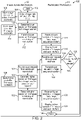
- FIG. 1 depicts a tomosynthesis image processing and review system (“tomosynthesis system”) 10 according to one embodiment.
- the tomosynthesis system 10 includes an image acquisition system 12 operatively coupled to a radiologist workstation 14 by a data connection such as a "network" 16.
- the image acquisition system is also known as a "host computer”
- the radiologist workstation is also known as a "user computer.”
- the "host computer” has more processing power than the "user computer,” and is operatively coupled to a plurality of "user computers” to facilitate simultaneous review by a plurality of users.
- the "host computer” functions as a data server.
- the "user computer” may be a workstation, a personal computer, or a tablet computer.
- the tomosynthesis system 10 also includes a DICOM-compliant Picture Archiving and Communication System (PACS) storage device 24 connected to the image acquisition system 12 and the radiologist workstation 14 through the network 16.
- PPS Picture Archiving and Communication System
- the image acquisition system 12 can include a tomosynthesis image acquisition device (e.g., an X-ray, not shown), or it can be a separate computer optimized for image processing.
- the radiologist workstation 14 includes one or more displays and a user input device 32 to facilitate user interaction with the tomosynthesis data.
- the user may be any trained observer, such as a reader, a technician, or a radiologist.
- the image acquisition system 12 and the radiologist workstation 14 can be located adjacent to each other. Alternatively, the image acquisition system 12 and the radiologist workstation 14 can be separated from each other by a significant distance.
- the data connection / "network" 16 may include two wired or wireless local area networks connected by one or more communication networks traversing large distances. Such multiple network connections 16 can only communicate as fast as the slowest network in the connection 16, taking into account the other traffic on each network.
- the image acquisition system 12 includes an image data processor 18 connected to an input / output module 20 and a memory module 22. While the depicted image acquisition system 12 includes a memory module 22, the memory module 22 may be located outside of the image acquisition system 12. In fact, the memory module 22 may be connected to the image acquisition system 12 by another connection / "network" over a large distance. In such tomosynthesis systems 10, whenever the image acquisition system 12 accesses (reads from and/or writes to) the memory module 22, traffic on this other connection / "network" increases.
- the input / output module 20 is configured to exchange data with another processor through a network 16.
- the image acquisition system 12 can optionally include an image generation module 26 configured to process raw tomosynthesis data into data that can be displayed as an image with a minimal amount of further processing.
- the image acquisition system 12 can also optionally include a computer aided detection (“CAD") module 28.
- the CAD module 28 is configured to process image data and identify FOIs therein. The function of the CAD module 28 is described, for example, in the references cited herein and in PCT patent application number PCT/US2013/025993 .
- the radiologist workstation 14 includes an image data processor 18 connected to an input / output module 20 and a memory module 22. While the depicted radiologist workstation 14 includes a memory module 22, the memory module 22 may be located outside of, and connected by another network, to the radiologist workstation 14.
- the input / output module 20 is configured to exchange data with another processor (for instance, with the image data processor 18 of the image acquisition system 12) through a network 16.
- the radiologist workstation 14 also includes an image generation module configured to process image data to generate an image for display on a display 30 of the radiologist workstation 14.
- the display 30 preferably includes more than one screen to present visual data to a user.
- the display 30 is also configured to present user interface objects to the user.
- the display 30 may be part of a standard acquisition workstation, or of a standard (multidisplay) review station that is physically remote from the acquisition system (not shown).
- a display 30 connected via a communication network may be used, for example, a display of a personal computer or of a so-called tablet, smart phone or other handheld device.
- the display 30 of the radiologist workstation 14 is preferably able to display tomosynthesis images concurrently, e.g., in separate side-by-side monitors. However, some embodiments may still be implemented with a single display monitor, by toggling between images.
- the radiologist workstation 14 also includes a user input device 32, such as, but not limited to, a pointing device (e.g., a mouse or a trackball), a touchscreen, a voice recognition device, and/or an eye movement sensing device.
- a user input device 32 such as, but not limited to, a pointing device (e.g., a mouse or a trackball), a touchscreen, a voice recognition device, and/or an eye movement sensing device.
- FIG. 2 illustrates the steps of a tomosynthesis data processing and review method 100, which incorporates the presently disclosed tomosynthesis system. It should be understood that, while FIG. 2 illustrates a particular embodiment of a flow diagram with certain processes taking place in a particular serial order or in parallel, various other embodiments are not limited to the performance of the image processing and display steps in any particular order, unless so specified.
- the illustrated method 100 is carried out on an image acquisition system 12 and a radiologist workstation 14.
- This method 100 provides the most advantages in embodiments where the image acquisition system 12 and the radiologist workstation 14 reside in respective distant locations.
- the computers 12, 14 are connected by one or more networks 16 (e.g., two wired or wireless local area networks connected by one or more communication networks traversing large distances).
- the illustrated method begins at the "start" icon 102 on the flow chart ( FIG. 2 ). In other embodiments, the method begins when a user at the radiologist workstation 14 initiates a review process. In still other embodiments, the method begins when the image acquisition system 12 is notified about available image data.
- the image acquisition system 12 obtains an image data set at step 104.
- the image data set represents the results of one or more tomosynthesis scans on one patient.
- the image data set can be Tp or Mp data.
- the image data set can be obtained directly from a tomosynthesis imaging device or from a memory module in which previously obtained image data has been stored.
- the image acquisition system 12 can obtain image data from legacy mammogram images in a storage device, such as a DICOM-compliant Picture Archiving and Communication System (PACS) storage device 17 connected to the image acquisition system 12 through a network 16.
- PPS Picture Archiving and Communication System
- the image acquisition system 12 can optionally store the obtained image data set or a selected subset thereof in a memory module 22 at step 106.
- the image data set is stored for an amount of time sufficient for a user to review and revisit the data (e.g., two months).
- the image data set is not typically stored indefinitely and may be purged to make room for new data after sufficient time has elapsed. Locating the tomosynthesis imaging device, the image acquisition system 12, and the memory module 22 within the same local area network increases the speed of image data communication on the image acquisition side of the method.
- some embodiments include memory modules that are separated from the tomosynthesis imaging device and the image acquisition system 12 by large distances. In such embodiments, any obtained or stored image data must travel through another network, slowing the review process.
- the image acquisition system 12 generates lower resolution images from the image data set. For instance, obtained Tp images can be reconstructed into reconstructed image "slabs" Tr, representing breast slices of selected thickness and at selected orientations, as disclosed in the above-incorporated patents and application publications.
- the method may also include highlighting FOI in the generated lower resolution images.
- a feature or object of interest in a source image may be considered a "most relevant" feature based upon the application of one or more CAD algorithms to the collective source images, wherein the CAD algorithms assign numerical values, weights or thresholds, to pixels or regions of the respective source images based upon identified/detected objects and features of interest within the respective region or between features.
- the pixel value, weight or other threshold associated with a pixel or region of the image may include, for example, spiculated lesions, calcifications, and the like.
- Various systems and methods are currently well known for computerized detection of abnormalities in radiographic images, such as those disclosed by Giger et al. in RadioGraphics, May 1993, pp. 647-656 ; Giger et al. in Proceedings of SPIE, Vol. 1445 (1991), pp. 101-103 ; U.S. Patent Nos. 4,907,156 , 5,133,020 , 5,343,390 , and 5,491,627 .
- “Generating a lower resolution image” refers to generating information that is sufficient to describe the lower resolution image for display and does not require actually displaying a lower resolution image.
- the resolution of lower resolution images varies depending on the capabilities of the image acquisition device and system. Typically, the lower resolution images have about 2/3 to about 1/5, and preferably about half the image resolution of higher resolution images (described below).
- the image resolution is inversely proportional to the resolution measured in pixel size (microns), such that doubling the image resolution is equal to halving the pixel size (microns).
- these lower resolution Tr images have a resolution of about 100 ⁇ m to about 280 ⁇ m, preferably about 100 ⁇ m to about 170 ⁇ m, and more preferably about 100 ⁇ m.
- Lower resolution Tr images are suitable for detection of FOIs because the smallest objects that should be detected, examined, and characterized, according to current standards of care for mammography, range from 150 ⁇ m to 500 ⁇ m in size.
- FOI include objects or regions of interest and are potential abnormalities such as calcifications and masses.
- the goal of the detection phase of image data review is to enable the user to notice or observe these small objects / FOIs. Therefore, the lower resolution Tr images are also called "detection images.” While the illustrated embodiment includes generating Tr images, the claims are not so limited. The claims encompass methods involving any images that are sufficient for detection of clinically relevant FOIs in accordance with the standard of care for mammography.
- the image acquisition system 12 can optionally store the lower resolution images in a memory module 22 at step 110.
- the lower resolution images are stored for an amount of time consistent with applicable rules and regulations in the jurisdiction, up to, and including, indefinitely.
- the smaller size of the lower resolution images reduces the amount of data storage space and the amount of network traffic required to comply with the rules and regulations, when compared to storing higher resolution images of the entire tomosynthesis volume.
- the image acquisition system 12 transmits the generated lower resolution images to the radiologist workstation 14.
- This transmission step uses a smaller amount of bandwidth in the multiple network connection 16 between the image acquisition system 12 and the radiologist workstation 14, when compared to transmitting higher resolution images of the entire tomosynthesis volume, because the transmitted images have a lower resolution than the maximum resolution allowed by the obtained image data set.
- the radiologist workstation 14 receives the transmitted lower resolution images from the image acquisition system 12. While the illustrated embodiment includes transmission and reception of images, the claims are not so limited. The claims encompass methods involving transmission and reception of image data from which images may be generated.
- the radiologist workstation 14 displays the lower resolution images, along with a user interface, on a display 30 to facilitate user interaction with the lower resolution image.
- This user interaction may involve other user input devices 32 (e.g., a mouse or a trackball) that are elements of the radiologist workstation 14.
- tomosynthesis image review continues with the characterization phase.
- the goal of the characterization phase is to facilitate user identification and categorization of the small objects previously noticed or observed in the detection phase.
- the lower resolution Tr images may be clinically sufficient to not only detect, but also to characterize the FOIs. For instance, benign calcifications are typically rounder and larger than malignant calcifications. In some cases, a 100 ⁇ m resolution image will be sufficient to make that clinical determination (in accordance with the standard of care for mammography) that a large and round calcification is benign. In such cases, no higher resolution image data is required.
- additional (higher resolution) images are required to characterize the detected FOIs.
- the user can interact with the displayed user interface and the user input device 32 to provide user requests to the radiologist workstation.
- Users may request higher resolution images of a specified subset of the tomosynthesis volume or the entire volume. These higher resolution images may correspond to some or all of the lower resolution images.
- the user request may be communicated in the form of 3D Cartesian coordinates or a point in 3D space and a radius, for instance.
- the user request may also include yaw/pitch/tilt information that connotes reconstruction in different planes with more degrees of freedom. Accordingly, the requested higher resolution images may differ from the displayed lower resolution images in slice thickness, pitch, yaw, and/or tilt.
- the user can communicate the user request by pointing to, hovering over, or otherwise indicating, one or more lower resolution images, or one or more FOIs (highlighted or not) on a lower resolution image.
- the selection of a region or area within a low resolution image may include a selection of a CAD mark, or alternatively a selection of a particular feature of interest to the reviewer.
- the CAD overlay may include CAD marks derived from the obtained image data.
- CAD marks derived from 3D data generally include, as part of the data object associated with the mark, identifiers of one or more slices which contributed to the generation of the 3D mark.
- selection of the CAD mark results in the generation and retrieval of higher resolution images corresponding to the series of slices that contributed to the mark, or may be limited to the portion of those high resolution slices that span the detected region within each image slice.
- the central image slice is first displayed; in alternate embodiments, the image slice having the highest weight is first displayed; in further alternate embodiments, the image slice having the sharpest image features is first displayed; and in a still further alternate embodiment, the image slice having the least visual noise (i.e., the clearest image) is first displayed.
- a mechanism for allowing a user to select any object or location on a low resolution image, for example, a feature of interest, such as any abnormality or irregularity in the image.
- the user or system may select a region, using for example a mouse click for a single pixel area, or a click and drag action to select a larger region.
- the user may be provided with a selection of graphical frames of various or variable sizes, and have the ability to move the frame to different locations within a lower resolution image to select areas when it is desired to view higher resolution image slices that display the features of interest.
- the radiologist workstation 14 receives the provided user request through the user interface at step 118.
- the radiologist workstation 14 determines whether it has received a user request for one or more higher resolution images. If the radiologist workstation 14 did not receive such a request, the illustrated method concludes at the "finish" icon 136 on the flow chart. If the radiologist workstation did receive a request for higher resolution images, the radiologist workstation 14 transmits the user request calling for higher resolution images to the image acquisition system 12 at step 122.
- the user request is transmitted through the multiple network connection 16 between the radiologist workstation 14 and the image acquisition system 12. Transmission of the user request uses a very small amount of bandwidth in the multiple network connection 16 because the user request is a small list of commands.
- the image acquisition system 12 receives the user request at step 124.
- the image acquisition system 12 generates the requested higher resolution images from the image data set based on the received user request.
- the resolution of higher resolution images varies depending on the capabilities of the image acquisition device and system.
- the higher resolution images have about 1.5 to about 5 times, and preferably about twice the image resolution of lower resolution images (described above).
- these higher resolution images can be Tr images at a resolution of about 50 ⁇ m to about 140 ⁇ m, preferably about 50 ⁇ m to about 85 ⁇ m, and more preferably about 70 ⁇ m, but are not limited to either Tr images, specific ratios of higher to lower resolutions, or specific resolutions.
- Higher resolution Tr images are suitable for characterization of the detected FOIs, because the resolution of the images allows them to clearly depict the FOIs and their features, which are used for characterization (e.g., border shape, inclusions, etc.) Therefore, the higher resolution Tr images are also called "characterization images.”
- the lower and higher resolution images may be actual images, reconstructed images, and/or a combination of the two.
- the method may also include highlighting FOI in the generated higher resolution images.
- the image acquisition system 12 can optionally store the higher resolution images in a memory module 22 at step 128.
- the lower resolution images are stored for an amount of time for an amount of time consistent with applicable rules and regulations, up to, and including, indefinitely.
- Embodiments in which the user requests only a subset of the tomosynthesis volume reduce the amount of data storage space required to comply with the rules and regulations, compared to storing higher resolution images of the entire tomosynthesis volume.
- the image acquisition system 12 transmits the generated higher resolution images, in accordance with the user request, to the radiologist workstation 14.
- the user requests only a subset of the tomosynthesis volume reduce the amount of bandwidth used for data transmission compared to transmitting higher resolution images of the entire tomosynthesis volume.
- the amount of data stored and the amount of data transmitted in steps 128 and 130, respectively, can be further reduced by avoiding storage and/or transmission of higher resolution image data that is duplicative of other higher resolution image data that either will be or already has been stored and/or transmitted. Accordingly, when higher resolution Tr images are generated in step 126, portions of the higher resolution Tr images that are duplicative of portions of other higher resolution Tr images previously generated will be replaced with data calls that identify the duplicated portions of the previously generated higher resolution Tr images. In this manner, the volume of the higher resolution Tr images to be generated, transmitted, and/or stored is reduced in size.
- the volume of the higher resolution Tr images depends on the user input received at step 118, and may include up to all image slices in the image data set.
- the radiologist workstation 14 receives the transmitted higher resolution images from the image acquisition system 12. While the illustrated embodiment includes transmission and reception of images, the claims are not so limited. The claims encompass methods involving transmission and reception of less processed image data from which images may be generated with additional processing.
- the radiologist workstation 14 displays the higher resolution images, along with a user interface, on a display 30 to facilitate user interaction with the higher resolution images. Using the displayed user interface and user input devices 32, the user can make additional user requests for more higher resolution images, including, and up to, higher resolution images of the entire tomosynthesis volume.
- the radiologist workstation 14 receives the user request at step 118. If the radiologist workstation 14 determines whether it has received a user request for one or more higher resolution images at step 120, the higher resolution image generation, transmission, and display steps are repeated at steps 122, 124, 126, 128, 130, 132, and 134, until no further user requests are received. At that time, the illustrated method concludes at the "finish" icon 136 on the flow chart ( FIG. 2 ).
- the image acquisition system 12 generates a complete set of higher resolution Tr images after the image data set is obtained at step 104. In still other embodiments, the image acquisition system 12 generates a set of higher resolution Tr images that contain CAD identified FOIs after the image data set is obtained at step 104. These embodiments are suitable for tomosynthesis systems 10 with powerful image data processors 18 and large memory module 22 for temporary storage of the generated higher resolution Tr images. Such embodiments conserve bandwidth on the networks 16 coupling the image acquisition system 12 to the radiologist workstation 14 by sending higher resolution Tr images to the radiologist workstation 14 only after a user reviews lower resolution Tr images and sends a user request through the radiologist workstation 14. The lower resolution Tr images may also include CAD markers identifying the FOIs to facilitate review. Pregenerating higher resolution Tr images accelerates system response time and the review process.
- the image acquisition system 12 generates a set of higher resolution Tr images that contain CAD identified FOIs after the image data set is obtained at step 104. These FOI containing higher resolution Tr images are transmitted to the radiologist workstation 14, for user review. After reviewing the FOI containing higher resolution Tr images, the user can send a user request for additional higher resolution Tr images. This embodiment partially reduces the amount of data generated, stored, and transmitted by generating higher resolution Tr images of only image slices containing CAD identified FOIs. Generating and transmitting FOI containing higher resolution Tr images further accelerates system response time and the review process.
- FIG. 3 illustrates a method 200 for generating and reviewing a tomosynthesis data set according to another embodiment.
- the illustrated method 200 is similar to the method depicted in FIG. 2 .
- the radiologist workstation 14 carries out more of the image processing for display. This method is suitable for radiologist workstations 14 with more robust image processors.
- the illustrated method begins at the "start" icon 202 on the flow chart.
- the image acquisition system 12 obtains an image data set at step 204.
- the image acquisition system 12 can optionally store the obtained image data set or a selected subset thereof in a memory module 22 at step 206. While no other storage of image data is depicted in FIG. 3 , any of the subsets of image data can be stored in a memory module 22.
- the image acquisition system 12 processes the obtained image data set to form (generate) a first image data subset.
- This first image data subset is sufficient to describe one or more lower resolution images for display. However, the first image data subset generated at step 208 cannot be displayed without further processing.
- the image acquisition system 12 transmits the generated first image data subset to the radiologist workstation 14.
- the radiologist workstation receives the transmitted first image data subset from the image acquisition system 12.
- the radiologist workstation 14 processes the first image data subset to form one or more lower resolution images.
- the radiologist workstation 14 displays the generated one or more lower resolution images, along with a user interface, on a display 30 to facilitate user interaction with the lower resolution image (detection images).
- the user can provide a user request to the radiologist workstation 14.
- the radiologist workstation 14 receives the provided user request through the user interface at step 218.
- the radiologist workstation 14 determines whether it has received a user request for one or more higher resolution images. If the radiologist workstation 14 did not receive such a request, the illustrated method concludes at the "finish" icon 236 on the flow chart. If the radiologist workstation 14 did receive a request for higher resolution images, the radiologist workstation 14 transmits the user request calling for higher resolution images to the image acquisition system 12 at step 222.
- the image acquisition system 12 receives the user request at step 224.
- the image acquisition system 12 generates a second image data subset from the image data set obtained in step 204 based on the received user request. Like the first image data subset, the second image data subset generated at step 226 cannot be displayed without further processing.
- the image acquisition system 12 transmits the generated second image data subset, in accordance with the user request, to the radiologist workstation 14.
- the radiologist workstation 14 receives the transmitted second image data subset from the image acquisition system 12.
- the radiologist workstation 14 processes the second image data subset to form one or more higher resolution images.
- the radiologist workstation 14 displays the higher resolution images, along with a user interface, on a display to facilitate user interaction with the higher resolution image.
- the user can make additional user requests for more higher resolution images, including, and up to, higher resolution images of the entire tomosynthesis volume.
- the radiologist workstation receives the user request at step 218. If the radiologist workstation determines whether it has received a user request for one or more higher resolution images at step 220, the higher resolution image generation, transmission, and display steps are repeated at steps 222, 224, 226, 228, 230, 232, and 234, until no further user requests are received. At that time, the illustrated method concludes at the "finish" icon 236 on the flow chart.
- the method depicted in FIG. 3 can also include highlighting of FOI during the generation of the first and second image data subsets.
Landscapes
- Engineering & Computer Science (AREA)
- Health & Medical Sciences (AREA)
- Life Sciences & Earth Sciences (AREA)
- Medical Informatics (AREA)
- Physics & Mathematics (AREA)
- Public Health (AREA)
- General Health & Medical Sciences (AREA)
- Biomedical Technology (AREA)
- Pathology (AREA)
- Nuclear Medicine, Radiotherapy & Molecular Imaging (AREA)
- Radiology & Medical Imaging (AREA)
- Animal Behavior & Ethology (AREA)
- Biophysics (AREA)
- Optics & Photonics (AREA)
- Veterinary Medicine (AREA)
- High Energy & Nuclear Physics (AREA)
- Heart & Thoracic Surgery (AREA)
- Molecular Biology (AREA)
- Surgery (AREA)
- General Physics & Mathematics (AREA)
- Theoretical Computer Science (AREA)
- Computer Vision & Pattern Recognition (AREA)
- Human Computer Interaction (AREA)
- Algebra (AREA)
- Dentistry (AREA)
- Pure & Applied Mathematics (AREA)
- Computer Networks & Wireless Communication (AREA)
- Mathematical Physics (AREA)
- Mathematical Optimization (AREA)
- Oral & Maxillofacial Surgery (AREA)
- Mathematical Analysis (AREA)
- Physiology (AREA)
- Epidemiology (AREA)
- Primary Health Care (AREA)
- Databases & Information Systems (AREA)
- Data Mining & Analysis (AREA)
- Quality & Reliability (AREA)
- Computer Graphics (AREA)
- Apparatus For Radiation Diagnosis (AREA)
Claims (15)
- Procédé mis en œuvre par ordinateur dans un système d'acquisition d'images (12) destiné au traitement et à la communication de données d'images de tissu mammaire, comprenant :l'obtention (104, 204) de données d'image du tissu mammaire d'une patiente ;le traitement (108, 208) des données d'image du tissu mammaire de la patiente pour former un premier sous-ensemble de celles-ci, le premier sous-ensemble de données d'image étant suffisant pour générer une ou plusieurs images à résolution inférieure d'au moins une partie du tissu mammaire de la patiente ;la transmission (112, 210) du premier sous-ensemble de données d'image à un ordinateur d'utilisateur (14) ;la réception (124, 224) d'une demande d'utilisateur pour des images à résolution supérieure à partir de l'ordinateur d'utilisateur en fonction de la ou des images à résolution inférieure ;le traitement (126, 226) des données d'image du tissu mammaire de la patiente pour former un second sous-ensemble de celles-ci, le second sous-ensemble de données d'image répondant à la demande d'utilisateur, et le second sous-ensemble de données d'image étant suffisant pour générer une ou plusieurs images à résolution supérieure du tissu mammaire de la patiente ; etla transmission (130, 228) du second sous-ensemble de données d'image à l'ordinateur d'utilisateur.
- Procédé dans un ordinateur d'utilisateur (14) destiné au traitement, à l'affichage et à la navigation des données d'images de tissu mammaire, comprenant :la réception (114, 212) d'un premier sous-ensemble de données d'image du tissu mammaire d'une patiente à partir d'un système d'acquisition d'images (12) ;le traitement (114, 214) du premier sous-ensemble de données d'images pour générer une ou plusieurs images à résolution inférieure du tissu mammaire de la patiente ;l'affichage (116, 216) de la ou des images à résolution inférieure ;la réception (118, 218) d'une demande d'utilisateur pour des images à résolution supérieure du tissu mammaire de la patiente ;la transmission (122, 222) de la demande d'utilisateur au système d'acquisition d'images ;la réception (132, 230) d'un second sous-ensemble de données d'image du tissu mammaire de la patiente à partir du système d'acquisition d'images, le second sous-ensemble de données d'image répondant à la demande d'utilisateur ; etle traitement (132, 232) du second sous-ensemble de données d'images pour générer une ou plusieurs images à résolution supérieure du tissu mammaire de la patiente ;l'affichage (134, 234) de la ou des images à résolution supérieure.
- Système d'acquisition d'images (12) destiné à être utilisé dans un système (10) destiné au traitement de données d'images de tissu mammaire,le système d'acquisition d'images étant configuré pour communiquer avec un ordinateur d'utilisateur (14),le système d'acquisition d'images étant configuré pour obtenir des données d'image du tissu mammaire d'une patiente,le système d'acquisition d'images étant en outre configuré pour former un premier sous-ensemble de données d'image, et transmettre le premier sous-ensemble de données d'image à un ordinateur d'utilisateur (14),le premier sous-ensemble de données d'image étant suffisant pour générer une ou plusieurs images à résolution inférieure d'au moins une partie du tissu mammaire de la patiente,le système d'acquisition d'images étant en outre configuré pour former un second sous-ensemble de données d'image du tissu mammaire de la patiente en réponse à une commande d'utilisateur reçue à partir de l'ordinateur d'utilisateur, et transmettre le second sous-ensemble de données d'image à un ordinateur d'utilisateur (14),le second sous-ensemble de données d'image étant suffisant pour générer une ou plusieurs images à résolution supérieure d'au moins une partie du tissu mammaire de la patiente.
- Ordinateur d'utilisateur (14) destiné à être utilisé dans un système (10) destiné au traitement de données d'images de tissu mammaire,l'ordinateur d'utilisateur étant configuré pour communiquer avec un système d'acquisition d'images (12) ;au moins un dispositif d'affichage (30) couplé fonctionnellement à l'ordinateur d'utilisateur ; etun dispositif d'entrée utilisateur (32) couplé fonctionnellement à l'ordinateur d'utilisateur,l'ordinateur d'utilisateur étant configuré pour recevoir un premier sous-ensemble de données d'image du tissu mammaire d'une patiente à partir du système d'acquisition d'images,l'ordinateur d'utilisateur étant en outre configuré pour traiter le premier sous-ensemble de données d'image pour générer une ou plusieurs images à résolution inférieure du tissu mammaire de la patiente,l'ordinateur d'utilisateur étant en outre configuré pour afficher la ou les images à résolution inférieure sur le dispositif d'affichage,l'ordinateur d'utilisateur étant en outre configuré pour recevoir une demande d'utilisateur pour des images à résolution supérieure du tissu mammaire de la patiente par le biais du dispositif d'entrée utilisateur,l'ordinateur d'utilisateur étant en outre configuré pour transmettre la demande d'utilisateur au système d'acquisition d'images,l'ordinateur d'utilisateur étant en outre configuré pour recevoir un second sous-ensemble de données d'image du tissu mammaire de la patiente à partir du système d'acquisition d'images,le second sous-ensemble de données d'image répondant à la demande d'utilisateur, etl'ordinateur d'utilisateur étant en outre configuré pour traiter le second sous-ensemble de données d'image pour générer une ou plusieurs images à résolution supérieure du tissu mammaire de la patiente, etl'ordinateur d'utilisateur étant en outre configuré pour afficher la ou les images à résolution supérieure sur le dispositif d'affichage.
- Procédé dans le système d'acquisition d'images selon la revendication 1, procédé dans l'ordinateur d'utilisateur selon la revendication 2, système d'acquisition d'images selon la revendication 3, ou ordinateur d'utilisateur selon la revendication 4, les données d'image comprenant :- des coupes de coordonnées X, Y acquises ou synthétisées à différents emplacements de l'axe z du sein de la patiente ; et/ou- une ou plusieurs images sélectionnées dans un groupe constitué d'images de projection de tomosynthèse, de coupes de reconstruction de tomosynthèse, d'images de mammographie, d'images de mammographie améliorée par contraste, d'images 2D synthétisées et leurs combinaisons.
- Procédé dans le système d'acquisition d'images selon la revendication 1 ou 5, procédé dans l'ordinateur d'utilisateur selon la revendication 2 ou 5, système d'acquisition d'images selon la revendication 3 ou 5, ou ordinateur d'utilisateur selon la revendication 4 ou 5, une résolution de la ou des images à résolution inférieure étant suffisante pour détecter une anomalie potentielle ou une région d'intérêt dans le tissu mammaire de la patiente.
- Procédé dans le système d'acquisition d'images selon la revendication 1 ou l'une quelconque des revendications 5 à 6, procédé dans l'ordinateur d'utilisateur selon la revendication 2 ou l'une quelconque des revendications 5 à 6, système d'acquisition d'images selon la revendication 3 ou l'une quelconque des revendications 5 à 6, ou ordinateur d'utilisateur selon la revendication 4 ou l'une quelconque des revendications 5 à 6, une résolution de la ou des images à résolution supérieure étant suffisante pour caractériser une anomalie potentielle ou une région d'intérêt dans le tissu mammaire de la patiente.
- Procédé dans le système d'acquisition d'images selon la revendication 1 ou l'une quelconque des revendications 5 à 7, procédé dans l'ordinateur d'utilisateur selon la revendication 2 ou l'une quelconque des revendications 5 à 7, système d'acquisition d'images selon la revendication 3 ou l'une quelconque des revendications 5 à 7, ou ordinateur d'utilisateur selon la revendication 4 ou l'une quelconque des revendications 5 à 7, la résolution de la ou des images à résolution supérieure étant comprise dans la plage d'environ 50 microns à environ 140 microns.
- Procédé dans le système d'acquisition d'images selon la revendication 8, procédé dans l'ordinateur d'utilisateur selon la revendication 8, système d'acquisition d'images selon la revendication 8, ou ordinateur d'utilisateur selon la revendication 8, la résolution de la ou des images à résolution supérieure étant comprise dans la plage d'environ 50 microns à environ 85 microns.
- Procédé dans le système d'acquisition d'images selon la revendication 9, procédé dans l'ordinateur d'utilisateur selon la revendication 9, système d'acquisition d'images selon la revendication 9, ou ordinateur d'utilisateur selon la revendication 9, la résolution de la ou des images à résolution supérieure étant d'environ 70 microns.
- Procédé dans le système d'acquisition d'images selon la revendication 1 ou l'une quelconque des revendications 5 à 10, procédé dans l'ordinateur d'utilisateur selon la revendication 2 ou l'une quelconque des revendications 5 à 10, système d'acquisition d'images selon la revendication 3 ou l'une quelconque des revendications 5 à 10, ou ordinateur d'utilisateur selon la revendication 4 ou l'une quelconque des revendications 5 à 10, la résolution de la ou des images à résolution supérieure étant d'environ 1,5 fois à 5 fois la résolution d'image de la ou des images à résolution inférieure.
- Procédé dans le système d'acquisition d'images selon la revendication 11, procédé dans l'ordinateur d'utilisateur selon la revendication 11, système d'acquisition d'images selon la revendication 11, ou ordinateur d'utilisateur selon la revendication 11, la résolution de la ou des images à résolution supérieure étant d'environ le double de la résolution d'image de la ou des images à résolution inférieure.
- Procédé dans le système d'acquisition d'images selon la revendication 1 ou l'une quelconque des revendications 5 à 12, procédé dans l'ordinateur d'utilisateur selon la revendication 2 ou l'une quelconque des revendications 5 à 12, système d'acquisition d'images selon la revendication 3 ou l'une quelconque des revendications 5 à 12, ou ordinateur d'utilisateur selon la revendication 4 ou l'une quelconque des revendications 5 à 12, le premier sous-ensemble de données d'image étant suffisant pour générer une ou plusieurs images à résolution inférieure du sein de la patiente dans lesquelles une caractéristique, un objet ou une région est automatiquement mis en évidence.
- Procédé dans le système d'acquisition d'images selon la revendication 1 ou l'une quelconque des revendications 5 à 13, procédé dans l'ordinateur d'utilisateur selon la revendication 2 ou l'une quelconque des revendications 5 à 13, système d'acquisition d'images selon la revendication 3 ou l'une quelconque des revendications 5 à 13, ou ordinateur d'utilisateur selon la revendication 4 ou l'une quelconque des revendications 5 à 13, la ou les images à basse résolution ayant une caractéristique différente de la caractéristique de la ou des images à haute résolution, et la caractéristique étant choisie dans le groupe constitué par l'épaisseur, le tangage, le lacet et l'inclinaison de la coupe.
- Procédé dans le système d'acquisition d'images selon la revendication 1 ou l'une quelconque des revendications 5 à 14, procédé dans l'ordinateur d'utilisateur selon la revendication 2 ou l'une quelconque des revendications 5 à 14, système d'acquisition d'images selon la revendication 3 ou l'une quelconque des revendications 5 à 14, ou ordinateur d'utilisateur selon la revendication 4 ou l'une quelconque des revendications 5 à 14, la demande d'utilisateur identifiant :- un objet ou une région d'intérêt dans la ou les images à résolution inférieure ; et/ou- une ou plusieurs images à résolution inférieure.
Applications Claiming Priority (2)
| Application Number | Priority Date | Filing Date | Title |
|---|---|---|---|
| US201361750840P | 2013-01-10 | 2013-01-10 | |
| PCT/US2014/010911 WO2014110283A1 (fr) | 2013-01-10 | 2014-01-09 | Système et procédé de réduction du volume de transmission de données en tomosynthèse |
Publications (3)
| Publication Number | Publication Date |
|---|---|
| EP2943913A1 EP2943913A1 (fr) | 2015-11-18 |
| EP2943913A4 EP2943913A4 (fr) | 2016-09-14 |
| EP2943913B1 true EP2943913B1 (fr) | 2022-07-13 |
Family
ID=51167375
Family Applications (1)
| Application Number | Title | Priority Date | Filing Date |
|---|---|---|---|
| EP14737752.7A Active EP2943913B1 (fr) | 2013-01-10 | 2014-01-09 | Système et procédé de réduction du volume de transmission de données en tomosynthèse |
Country Status (4)
| Country | Link |
|---|---|
| US (1) | US9940738B2 (fr) |
| EP (1) | EP2943913B1 (fr) |
| JP (1) | JP6360495B2 (fr) |
| WO (1) | WO2014110283A1 (fr) |
Families Citing this family (7)
| Publication number | Priority date | Publication date | Assignee | Title |
|---|---|---|---|---|
| JP6360495B2 (ja) | 2013-01-10 | 2018-07-18 | ホロジック, インコーポレイテッドHologic, Inc. | トモシンセシスにおけるデータ伝送ボリュームを低減するための方法 |
| US10372876B2 (en) * | 2017-01-20 | 2019-08-06 | Agfa Healthcare Inc. | System and method for providing breast image data |
| EP3518182B1 (fr) * | 2018-01-26 | 2022-05-18 | Siemens Healthcare GmbH | Tranches inclinées en dbt |
| US11382594B2 (en) * | 2018-12-31 | 2022-07-12 | General Electric Company | Systems and methods for interventional radiology with remote processing |
| WO2021157182A1 (fr) * | 2020-02-04 | 2021-08-12 | 富士フイルム株式会社 | Dispositif, procédé et programme de réglage d'image |
| JP7270781B2 (ja) | 2020-02-04 | 2023-05-10 | 富士フイルム株式会社 | 画像設定装置、画像設定装置の作動方法および画像設定プログラム |
| EP4101386A4 (fr) | 2020-02-04 | 2023-07-12 | FUJIFILM Corporation | Dispositif de réglage d'image, procédé et programme |
Family Cites Families (24)
| Publication number | Priority date | Publication date | Assignee | Title |
|---|---|---|---|---|
| US4907156A (en) | 1987-06-30 | 1990-03-06 | University Of Chicago | Method and system for enhancement and detection of abnormal anatomic regions in a digital image |
| US5133020A (en) | 1989-07-21 | 1992-07-21 | Arch Development Corporation | Automated method and system for the detection and classification of abnormal lesions and parenchymal distortions in digital medical images |
| US5343390A (en) | 1992-02-28 | 1994-08-30 | Arch Development Corporation | Method and system for automated selection of regions of interest and detection of septal lines in digital chest radiographs |
| US5491627A (en) | 1993-05-13 | 1996-02-13 | Arch Development Corporation | Method and system for the detection of microcalcifications in digital mammograms |
| US6847729B1 (en) | 1999-04-21 | 2005-01-25 | Fairfield Imaging Limited | Microscopy |
| US6421454B1 (en) | 1999-05-27 | 2002-07-16 | Litton Systems, Inc. | Optical correlator assisted detection of calcifications for breast biopsy |
| US7577282B2 (en) | 2002-11-27 | 2009-08-18 | Hologic, Inc. | Image handling and display in X-ray mammography and tomosynthesis |
| US8571289B2 (en) | 2002-11-27 | 2013-10-29 | Hologic, Inc. | System and method for generating a 2D image from a tomosynthesis data set |
| US7760924B2 (en) | 2002-11-27 | 2010-07-20 | Hologic, Inc. | System and method for generating a 2D image from a tomosynthesis data set |
| US7660488B2 (en) * | 2004-11-04 | 2010-02-09 | Dr Systems, Inc. | Systems and methods for viewing medical images |
| EP1815388B1 (fr) | 2004-11-15 | 2013-03-06 | Hologic, Inc. | Generation et affichage geometriques de mise en correspondance de cliches mammaires et d'images de tomosynthese |
| JP2006223449A (ja) | 2005-02-16 | 2006-08-31 | Fuji Photo Film Co Ltd | 断面表示装置、及び、そのプログラム |
| US7606801B2 (en) | 2005-06-07 | 2009-10-20 | Varonis Inc. | Automatic management of storage access control |
| US20070242868A1 (en) | 2005-11-09 | 2007-10-18 | Dexela Limited | Methods and apparatus for displaying images |
| US7515682B2 (en) * | 2006-02-02 | 2009-04-07 | General Electric Company | Method and system to generate object image slices |
| US7511723B2 (en) * | 2006-03-31 | 2009-03-31 | Research In Motion Limited | Method for requesting and viewing an attachment image on a portable electronic device |
| EP2036003B1 (fr) * | 2006-06-30 | 2017-05-03 | Leica Biosystems Imaging, Inc. | Procédé de stockage et de récuperation de grandes images par dicom |
| JP2009066306A (ja) | 2007-09-14 | 2009-04-02 | Fujifilm Corp | 画像表示方法及び画像表示システム |
| US8126226B2 (en) | 2007-09-20 | 2012-02-28 | General Electric Company | System and method to generate a selected visualization of a radiological image of an imaged subject |
| US8948496B2 (en) * | 2008-08-29 | 2015-02-03 | Koninklijke Philips N.V. | Dynamic transfer of three-dimensional image data |
| US8296359B2 (en) | 2010-07-12 | 2012-10-23 | Opus Medicus, Inc. | Systems and methods for networked, in-context, high resolution image viewing |
| US20120324397A1 (en) | 2011-06-20 | 2012-12-20 | Tabb Alan Patz | System and method for wireless interaction with medical image data |
| CN104135935A (zh) | 2012-02-13 | 2014-11-05 | 霍罗吉克公司 | 用于利用合成图像数据导航层析堆的系统和方法 |
| JP6360495B2 (ja) | 2013-01-10 | 2018-07-18 | ホロジック, インコーポレイテッドHologic, Inc. | トモシンセシスにおけるデータ伝送ボリュームを低減するための方法 |
-
2014
- 2014-01-09 JP JP2015552780A patent/JP6360495B2/ja active Active
- 2014-01-09 WO PCT/US2014/010911 patent/WO2014110283A1/fr active Application Filing
- 2014-01-09 EP EP14737752.7A patent/EP2943913B1/fr active Active
- 2014-01-09 US US14/760,035 patent/US9940738B2/en active Active
Also Published As
| Publication number | Publication date |
|---|---|
| US9940738B2 (en) | 2018-04-10 |
| JP2016502917A (ja) | 2016-02-01 |
| EP2943913A4 (fr) | 2016-09-14 |
| WO2014110283A1 (fr) | 2014-07-17 |
| US20150356757A1 (en) | 2015-12-10 |
| JP6360495B2 (ja) | 2018-07-18 |
| EP2943913A1 (fr) | 2015-11-18 |
Similar Documents
| Publication | Publication Date | Title |
|---|---|---|
| EP2943913B1 (fr) | Système et procédé de réduction du volume de transmission de données en tomosynthèse | |
| CN109791692B (zh) | 使用来自感兴趣区域的不同视角的多个图像进行计算机辅助检测以提高检测准确度的系统和方法 | |
| US11801025B2 (en) | System and method for generating and displaying tomosynthesis image slabs | |
| US11983799B2 (en) | System and method for synthesizing low-dimensional image data from high-dimensional image data using an object grid enhancement | |
| JP6208731B2 (ja) | トモシンセシスデータセットから2d画像を生成するためのシステムおよび方法 | |
| WO2018183548A1 (fr) | Système et procédé de synthèse et de représentation d'image de caractéristique multiniveau hiérarchique | |
| EP3315072A1 (fr) | Système et procédé pour naviguer dans une pile de tomosynthèse par utilisation de données d'images synthétisées | |
| US20150139518A1 (en) | Image processing apparatus | |
| EP2967473A1 (fr) | Système et procédé pour explorer une pile de tomosynthèse comprenant une mise au point automatique | |
| KR102545008B1 (ko) | 초음파 영상 장치 및 그 제어 방법 | |
| KR20180086773A (ko) | 평면 보간 기반 2차원 의료 영상을 생성하는 방법 및 장치 |
Legal Events
| Date | Code | Title | Description |
|---|---|---|---|
| PUAI | Public reference made under article 153(3) epc to a published international application that has entered the european phase |
Free format text: ORIGINAL CODE: 0009012 |
|
| 17P | Request for examination filed |
Effective date: 20150807 |
|
| AK | Designated contracting states |
Kind code of ref document: A1 Designated state(s): AL AT BE BG CH CY CZ DE DK EE ES FI FR GB GR HR HU IE IS IT LI LT LU LV MC MK MT NL NO PL PT RO RS SE SI SK SM TR |
|
| AX | Request for extension of the european patent |
Extension state: BA ME |
|
| DAX | Request for extension of the european patent (deleted) | ||
| A4 | Supplementary search report drawn up and despatched |
Effective date: 20160811 |
|
| RIC1 | Information provided on ipc code assigned before grant |
Ipc: G06T 7/00 20060101ALI20160805BHEP Ipc: A61B 6/00 20060101ALI20160805BHEP Ipc: G06K 9/36 20060101AFI20160805BHEP Ipc: G06F 19/00 20110101ALI20160805BHEP |
|
| RAP1 | Party data changed (applicant data changed or rights of an application transferred) |
Owner name: HOLOGIC INC. |
|
| STAA | Information on the status of an ep patent application or granted ep patent |
Free format text: STATUS: EXAMINATION IS IN PROGRESS |
|
| 17Q | First examination report despatched |
Effective date: 20190612 |
|
| RAP1 | Party data changed (applicant data changed or rights of an application transferred) |
Owner name: HOLOGIC, INC. |
|
| STAA | Information on the status of an ep patent application or granted ep patent |
Free format text: STATUS: EXAMINATION IS IN PROGRESS |
|
| REG | Reference to a national code |
Ref country code: DE Ref legal event code: R079 Ref document number: 602014084283 Country of ref document: DE Free format text: PREVIOUS MAIN CLASS: G06K0009360000 Ipc: G06K0009000000 |
|
| GRAP | Despatch of communication of intention to grant a patent |
Free format text: ORIGINAL CODE: EPIDOSNIGR1 |
|
| STAA | Information on the status of an ep patent application or granted ep patent |
Free format text: STATUS: GRANT OF PATENT IS INTENDED |
|
| RIC1 | Information provided on ipc code assigned before grant |
Ipc: G06T 7/00 20170101ALI20211220BHEP Ipc: A61B 6/00 20060101ALI20211220BHEP Ipc: G06K 9/36 20060101AFI20211220BHEP |
|
| INTG | Intention to grant announced |
Effective date: 20220126 |
|
| RIC1 | Information provided on ipc code assigned before grant |
Ipc: G06T 7/00 20060101ALI20220121BHEP Ipc: A61B 6/00 20060101ALI20220121BHEP Ipc: G06K 9/00 20060101AFI20220121BHEP |
|
| GRAS | Grant fee paid |
Free format text: ORIGINAL CODE: EPIDOSNIGR3 |
|
| GRAA | (expected) grant |
Free format text: ORIGINAL CODE: 0009210 |
|
| STAA | Information on the status of an ep patent application or granted ep patent |
Free format text: STATUS: THE PATENT HAS BEEN GRANTED |
|
| AK | Designated contracting states |
Kind code of ref document: B1 Designated state(s): AL AT BE BG CH CY CZ DE DK EE ES FI FR GB GR HR HU IE IS IT LI LT LU LV MC MK MT NL NO PL PT RO RS SE SI SK SM TR |
|
| REG | Reference to a national code |
Ref country code: GB Ref legal event code: FG4D |
|
| REG | Reference to a national code |
Ref country code: CH Ref legal event code: EP |
|
| REG | Reference to a national code |
Ref country code: IE Ref legal event code: FG4D |
|
| REG | Reference to a national code |
Ref country code: DE Ref legal event code: R096 Ref document number: 602014084283 Country of ref document: DE |
|
| REG | Reference to a national code |
Ref country code: AT Ref legal event code: REF Ref document number: 1504647 Country of ref document: AT Kind code of ref document: T Effective date: 20220815 |
|
| REG | Reference to a national code |
Ref country code: LT Ref legal event code: MG9D |
|
| REG | Reference to a national code |
Ref country code: NL Ref legal event code: MP Effective date: 20220713 |
|
| REG | Reference to a national code |
Ref country code: DE Ref legal event code: R079 Ref document number: 602014084283 Country of ref document: DE Free format text: PREVIOUS MAIN CLASS: G06K0009000000 Ipc: G06V0010000000 |
|
| PG25 | Lapsed in a contracting state [announced via postgrant information from national office to epo] |
Ref country code: SE Free format text: LAPSE BECAUSE OF FAILURE TO SUBMIT A TRANSLATION OF THE DESCRIPTION OR TO PAY THE FEE WITHIN THE PRESCRIBED TIME-LIMIT Effective date: 20220713 Ref country code: RS Free format text: LAPSE BECAUSE OF FAILURE TO SUBMIT A TRANSLATION OF THE DESCRIPTION OR TO PAY THE FEE WITHIN THE PRESCRIBED TIME-LIMIT Effective date: 20220713 Ref country code: PT Free format text: LAPSE BECAUSE OF FAILURE TO SUBMIT A TRANSLATION OF THE DESCRIPTION OR TO PAY THE FEE WITHIN THE PRESCRIBED TIME-LIMIT Effective date: 20221114 Ref country code: NO Free format text: LAPSE BECAUSE OF FAILURE TO SUBMIT A TRANSLATION OF THE DESCRIPTION OR TO PAY THE FEE WITHIN THE PRESCRIBED TIME-LIMIT Effective date: 20221013 Ref country code: NL Free format text: LAPSE BECAUSE OF FAILURE TO SUBMIT A TRANSLATION OF THE DESCRIPTION OR TO PAY THE FEE WITHIN THE PRESCRIBED TIME-LIMIT Effective date: 20220713 Ref country code: LV Free format text: LAPSE BECAUSE OF FAILURE TO SUBMIT A TRANSLATION OF THE DESCRIPTION OR TO PAY THE FEE WITHIN THE PRESCRIBED TIME-LIMIT Effective date: 20220713 Ref country code: LT Free format text: LAPSE BECAUSE OF FAILURE TO SUBMIT A TRANSLATION OF THE DESCRIPTION OR TO PAY THE FEE WITHIN THE PRESCRIBED TIME-LIMIT Effective date: 20220713 Ref country code: FI Free format text: LAPSE BECAUSE OF FAILURE TO SUBMIT A TRANSLATION OF THE DESCRIPTION OR TO PAY THE FEE WITHIN THE PRESCRIBED TIME-LIMIT Effective date: 20220713 Ref country code: ES Free format text: LAPSE BECAUSE OF FAILURE TO SUBMIT A TRANSLATION OF THE DESCRIPTION OR TO PAY THE FEE WITHIN THE PRESCRIBED TIME-LIMIT Effective date: 20220713 |
|
| REG | Reference to a national code |
Ref country code: AT Ref legal event code: MK05 Ref document number: 1504647 Country of ref document: AT Kind code of ref document: T Effective date: 20220713 |
|
| PG25 | Lapsed in a contracting state [announced via postgrant information from national office to epo] |
Ref country code: PL Free format text: LAPSE BECAUSE OF FAILURE TO SUBMIT A TRANSLATION OF THE DESCRIPTION OR TO PAY THE FEE WITHIN THE PRESCRIBED TIME-LIMIT Effective date: 20220713 Ref country code: IS Free format text: LAPSE BECAUSE OF FAILURE TO SUBMIT A TRANSLATION OF THE DESCRIPTION OR TO PAY THE FEE WITHIN THE PRESCRIBED TIME-LIMIT Effective date: 20221113 Ref country code: HR Free format text: LAPSE BECAUSE OF FAILURE TO SUBMIT A TRANSLATION OF THE DESCRIPTION OR TO PAY THE FEE WITHIN THE PRESCRIBED TIME-LIMIT Effective date: 20220713 Ref country code: GR Free format text: LAPSE BECAUSE OF FAILURE TO SUBMIT A TRANSLATION OF THE DESCRIPTION OR TO PAY THE FEE WITHIN THE PRESCRIBED TIME-LIMIT Effective date: 20221014 |
|
| REG | Reference to a national code |
Ref country code: DE Ref legal event code: R097 Ref document number: 602014084283 Country of ref document: DE |
|
| PG25 | Lapsed in a contracting state [announced via postgrant information from national office to epo] |
Ref country code: SM Free format text: LAPSE BECAUSE OF FAILURE TO SUBMIT A TRANSLATION OF THE DESCRIPTION OR TO PAY THE FEE WITHIN THE PRESCRIBED TIME-LIMIT Effective date: 20220713 Ref country code: RO Free format text: LAPSE BECAUSE OF FAILURE TO SUBMIT A TRANSLATION OF THE DESCRIPTION OR TO PAY THE FEE WITHIN THE PRESCRIBED TIME-LIMIT Effective date: 20220713 Ref country code: DK Free format text: LAPSE BECAUSE OF FAILURE TO SUBMIT A TRANSLATION OF THE DESCRIPTION OR TO PAY THE FEE WITHIN THE PRESCRIBED TIME-LIMIT Effective date: 20220713 Ref country code: CZ Free format text: LAPSE BECAUSE OF FAILURE TO SUBMIT A TRANSLATION OF THE DESCRIPTION OR TO PAY THE FEE WITHIN THE PRESCRIBED TIME-LIMIT Effective date: 20220713 Ref country code: AT Free format text: LAPSE BECAUSE OF FAILURE TO SUBMIT A TRANSLATION OF THE DESCRIPTION OR TO PAY THE FEE WITHIN THE PRESCRIBED TIME-LIMIT Effective date: 20220713 |
|
| PGFP | Annual fee paid to national office [announced via postgrant information from national office to epo] |
Ref country code: FR Payment date: 20230125 Year of fee payment: 10 |
|
| PLBE | No opposition filed within time limit |
Free format text: ORIGINAL CODE: 0009261 |
|
| STAA | Information on the status of an ep patent application or granted ep patent |
Free format text: STATUS: NO OPPOSITION FILED WITHIN TIME LIMIT |
|
| PG25 | Lapsed in a contracting state [announced via postgrant information from national office to epo] |
Ref country code: SK Free format text: LAPSE BECAUSE OF FAILURE TO SUBMIT A TRANSLATION OF THE DESCRIPTION OR TO PAY THE FEE WITHIN THE PRESCRIBED TIME-LIMIT Effective date: 20220713 Ref country code: EE Free format text: LAPSE BECAUSE OF FAILURE TO SUBMIT A TRANSLATION OF THE DESCRIPTION OR TO PAY THE FEE WITHIN THE PRESCRIBED TIME-LIMIT Effective date: 20220713 |
|
| 26N | No opposition filed |
Effective date: 20230414 |
|
| PG25 | Lapsed in a contracting state [announced via postgrant information from national office to epo] |
Ref country code: AL Free format text: LAPSE BECAUSE OF FAILURE TO SUBMIT A TRANSLATION OF THE DESCRIPTION OR TO PAY THE FEE WITHIN THE PRESCRIBED TIME-LIMIT Effective date: 20220713 |
|
| P01 | Opt-out of the competence of the unified patent court (upc) registered |
Effective date: 20230526 |
|
| PG25 | Lapsed in a contracting state [announced via postgrant information from national office to epo] |
Ref country code: SI Free format text: LAPSE BECAUSE OF FAILURE TO SUBMIT A TRANSLATION OF THE DESCRIPTION OR TO PAY THE FEE WITHIN THE PRESCRIBED TIME-LIMIT Effective date: 20220713 |
|
| REG | Reference to a national code |
Ref country code: CH Ref legal event code: PL |
|
| PG25 | Lapsed in a contracting state [announced via postgrant information from national office to epo] |
Ref country code: LU Free format text: LAPSE BECAUSE OF NON-PAYMENT OF DUE FEES Effective date: 20230109 |
|
| REG | Reference to a national code |
Ref country code: BE Ref legal event code: MM Effective date: 20230131 |
|
| PG25 | Lapsed in a contracting state [announced via postgrant information from national office to epo] |
Ref country code: LI Free format text: LAPSE BECAUSE OF NON-PAYMENT OF DUE FEES Effective date: 20230131 Ref country code: CH Free format text: LAPSE BECAUSE OF NON-PAYMENT OF DUE FEES Effective date: 20230131 |
|
| PG25 | Lapsed in a contracting state [announced via postgrant information from national office to epo] |
Ref country code: BE Free format text: LAPSE BECAUSE OF NON-PAYMENT OF DUE FEES Effective date: 20230131 |
|
| PG25 | Lapsed in a contracting state [announced via postgrant information from national office to epo] |
Ref country code: IT Free format text: LAPSE BECAUSE OF FAILURE TO SUBMIT A TRANSLATION OF THE DESCRIPTION OR TO PAY THE FEE WITHIN THE PRESCRIBED TIME-LIMIT Effective date: 20220713 Ref country code: IE Free format text: LAPSE BECAUSE OF NON-PAYMENT OF DUE FEES Effective date: 20230109 |
|
| PGFP | Annual fee paid to national office [announced via postgrant information from national office to epo] |
Ref country code: DE Payment date: 20240129 Year of fee payment: 11 Ref country code: GB Payment date: 20240129 Year of fee payment: 11 |