EP2942897B1 - Procédé et appareil de transmission de signaux de liaison montante dans un système de communication sans fil - Google Patents
Procédé et appareil de transmission de signaux de liaison montante dans un système de communication sans fil Download PDFInfo
- Publication number
- EP2942897B1 EP2942897B1 EP14735393.2A EP14735393A EP2942897B1 EP 2942897 B1 EP2942897 B1 EP 2942897B1 EP 14735393 A EP14735393 A EP 14735393A EP 2942897 B1 EP2942897 B1 EP 2942897B1
- Authority
- EP
- European Patent Office
- Prior art keywords
- cell
- ack
- transmission
- nack
- pucch
- Prior art date
- Legal status (The legal status is an assumption and is not a legal conclusion. Google has not performed a legal analysis and makes no representation as to the accuracy of the status listed.)
- Active
Links
Images


Classifications
-
- H—ELECTRICITY
- H04—ELECTRIC COMMUNICATION TECHNIQUE
- H04W—WIRELESS COMMUNICATION NETWORKS
- H04W52/00—Power management, e.g. TPC [Transmission Power Control], power saving or power classes
- H04W52/04—TPC
- H04W52/06—TPC algorithms
- H04W52/14—Separate analysis of uplink or downlink
- H04W52/146—Uplink power control
-
- H—ELECTRICITY
- H04—ELECTRIC COMMUNICATION TECHNIQUE
- H04L—TRANSMISSION OF DIGITAL INFORMATION, e.g. TELEGRAPHIC COMMUNICATION
- H04L1/00—Arrangements for detecting or preventing errors in the information received
- H04L1/12—Arrangements for detecting or preventing errors in the information received by using return channel
- H04L1/16—Arrangements for detecting or preventing errors in the information received by using return channel in which the return channel carries supervisory signals, e.g. repetition request signals
- H04L1/18—Automatic repetition systems, e.g. Van Duuren systems
- H04L1/1829—Arrangements specially adapted for the receiver end
- H04L1/1854—Scheduling and prioritising arrangements
-
- H—ELECTRICITY
- H04—ELECTRIC COMMUNICATION TECHNIQUE
- H04L—TRANSMISSION OF DIGITAL INFORMATION, e.g. TELEGRAPHIC COMMUNICATION
- H04L1/00—Arrangements for detecting or preventing errors in the information received
- H04L1/12—Arrangements for detecting or preventing errors in the information received by using return channel
- H04L1/16—Arrangements for detecting or preventing errors in the information received by using return channel in which the return channel carries supervisory signals, e.g. repetition request signals
- H04L1/18—Automatic repetition systems, e.g. Van Duuren systems
- H04L1/1829—Arrangements specially adapted for the receiver end
- H04L1/1861—Physical mapping arrangements
-
- H—ELECTRICITY
- H04—ELECTRIC COMMUNICATION TECHNIQUE
- H04L—TRANSMISSION OF DIGITAL INFORMATION, e.g. TELEGRAPHIC COMMUNICATION
- H04L27/00—Modulated-carrier systems
- H04L27/26—Systems using multi-frequency codes
- H04L27/2601—Multicarrier modulation systems
- H04L27/2602—Signal structure
- H04L27/2605—Symbol extensions, e.g. Zero Tail, Unique Word [UW]
- H04L27/2607—Cyclic extensions
-
- H—ELECTRICITY
- H04—ELECTRIC COMMUNICATION TECHNIQUE
- H04L—TRANSMISSION OF DIGITAL INFORMATION, e.g. TELEGRAPHIC COMMUNICATION
- H04L5/00—Arrangements affording multiple use of the transmission path
-
- H—ELECTRICITY
- H04—ELECTRIC COMMUNICATION TECHNIQUE
- H04L—TRANSMISSION OF DIGITAL INFORMATION, e.g. TELEGRAPHIC COMMUNICATION
- H04L5/00—Arrangements affording multiple use of the transmission path
- H04L5/0001—Arrangements for dividing the transmission path
- H04L5/0003—Two-dimensional division
- H04L5/0005—Time-frequency
- H04L5/0007—Time-frequency the frequencies being orthogonal, e.g. OFDM(A), DMT
- H04L5/001—Time-frequency the frequencies being orthogonal, e.g. OFDM(A), DMT the frequencies being arranged in component carriers
-
- H—ELECTRICITY
- H04—ELECTRIC COMMUNICATION TECHNIQUE
- H04L—TRANSMISSION OF DIGITAL INFORMATION, e.g. TELEGRAPHIC COMMUNICATION
- H04L5/00—Arrangements affording multiple use of the transmission path
- H04L5/003—Arrangements for allocating sub-channels of the transmission path
- H04L5/0053—Allocation of signaling, i.e. of overhead other than pilot signals
- H04L5/0055—Physical resource allocation for ACK/NACK
-
- H—ELECTRICITY
- H04—ELECTRIC COMMUNICATION TECHNIQUE
- H04L—TRANSMISSION OF DIGITAL INFORMATION, e.g. TELEGRAPHIC COMMUNICATION
- H04L5/00—Arrangements affording multiple use of the transmission path
- H04L5/14—Two-way operation using the same type of signal, i.e. duplex
-
- H—ELECTRICITY
- H04—ELECTRIC COMMUNICATION TECHNIQUE
- H04W—WIRELESS COMMUNICATION NETWORKS
- H04W52/00—Power management, e.g. TPC [Transmission Power Control], power saving or power classes
- H04W52/04—TPC
- H04W52/18—TPC being performed according to specific parameters
- H04W52/28—TPC being performed according to specific parameters using user profile, e.g. mobile speed, priority or network state, e.g. standby, idle or non transmission
- H04W52/281—TPC being performed according to specific parameters using user profile, e.g. mobile speed, priority or network state, e.g. standby, idle or non transmission taking into account user or data type priority
-
- H—ELECTRICITY
- H04—ELECTRIC COMMUNICATION TECHNIQUE
- H04W—WIRELESS COMMUNICATION NETWORKS
- H04W52/00—Power management, e.g. TPC [Transmission Power Control], power saving or power classes
- H04W52/04—TPC
- H04W52/30—TPC using constraints in the total amount of available transmission power
- H04W52/32—TPC of broadcast or control channels
- H04W52/325—Power control of control or pilot channels
-
- H—ELECTRICITY
- H04—ELECTRIC COMMUNICATION TECHNIQUE
- H04W—WIRELESS COMMUNICATION NETWORKS
- H04W52/00—Power management, e.g. TPC [Transmission Power Control], power saving or power classes
- H04W52/04—TPC
- H04W52/30—TPC using constraints in the total amount of available transmission power
- H04W52/36—TPC using constraints in the total amount of available transmission power with a discrete range or set of values, e.g. step size, ramping or offsets
- H04W52/367—Power values between minimum and maximum limits, e.g. dynamic range
-
- H—ELECTRICITY
- H04—ELECTRIC COMMUNICATION TECHNIQUE
- H04W—WIRELESS COMMUNICATION NETWORKS
- H04W52/00—Power management, e.g. TPC [Transmission Power Control], power saving or power classes
- H04W52/04—TPC
- H04W52/38—TPC being performed in particular situations
- H04W52/50—TPC being performed in particular situations at the moment of starting communication in a multiple access environment
-
- H—ELECTRICITY
- H04—ELECTRIC COMMUNICATION TECHNIQUE
- H04W—WIRELESS COMMUNICATION NETWORKS
- H04W52/00—Power management, e.g. TPC [Transmission Power Control], power saving or power classes
- H04W52/04—TPC
- H04W52/54—Signalisation aspects of the TPC commands, e.g. frame structure
- H04W52/58—Format of the TPC bits
-
- H—ELECTRICITY
- H04—ELECTRIC COMMUNICATION TECHNIQUE
- H04W—WIRELESS COMMUNICATION NETWORKS
- H04W72/00—Local resource management
- H04W72/04—Wireless resource allocation
- H04W72/044—Wireless resource allocation based on the type of the allocated resource
- H04W72/0453—Resources in frequency domain, e.g. a carrier in FDMA
-
- H—ELECTRICITY
- H04—ELECTRIC COMMUNICATION TECHNIQUE
- H04W—WIRELESS COMMUNICATION NETWORKS
- H04W72/00—Local resource management
- H04W72/20—Control channels or signalling for resource management
-
- H—ELECTRICITY
- H04—ELECTRIC COMMUNICATION TECHNIQUE
- H04W—WIRELESS COMMUNICATION NETWORKS
- H04W72/00—Local resource management
- H04W72/20—Control channels or signalling for resource management
- H04W72/21—Control channels or signalling for resource management in the uplink direction of a wireless link, i.e. towards the network
-
- H—ELECTRICITY
- H04—ELECTRIC COMMUNICATION TECHNIQUE
- H04L—TRANSMISSION OF DIGITAL INFORMATION, e.g. TELEGRAPHIC COMMUNICATION
- H04L1/00—Arrangements for detecting or preventing errors in the information received
- H04L1/12—Arrangements for detecting or preventing errors in the information received by using return channel
- H04L1/16—Arrangements for detecting or preventing errors in the information received by using return channel in which the return channel carries supervisory signals, e.g. repetition request signals
- H04L1/1607—Details of the supervisory signal
- H04L1/1671—Details of the supervisory signal the supervisory signal being transmitted together with control information
-
- H—ELECTRICITY
- H04—ELECTRIC COMMUNICATION TECHNIQUE
- H04W—WIRELESS COMMUNICATION NETWORKS
- H04W52/00—Power management, e.g. TPC [Transmission Power Control], power saving or power classes
- H04W52/04—TPC
- H04W52/30—TPC using constraints in the total amount of available transmission power
- H04W52/34—TPC management, i.e. sharing limited amount of power among users or channels or data types, e.g. cell loading
-
- H—ELECTRICITY
- H04—ELECTRIC COMMUNICATION TECHNIQUE
- H04W—WIRELESS COMMUNICATION NETWORKS
- H04W52/00—Power management, e.g. TPC [Transmission Power Control], power saving or power classes
- H04W52/04—TPC
- H04W52/30—TPC using constraints in the total amount of available transmission power
- H04W52/36—TPC using constraints in the total amount of available transmission power with a discrete range or set of values, e.g. step size, ramping or offsets
- H04W52/365—Power headroom reporting
-
- H—ELECTRICITY
- H04—ELECTRIC COMMUNICATION TECHNIQUE
- H04W—WIRELESS COMMUNICATION NETWORKS
- H04W52/00—Power management, e.g. TPC [Transmission Power Control], power saving or power classes
- H04W52/04—TPC
- H04W52/38—TPC being performed in particular situations
- H04W52/40—TPC being performed in particular situations during macro-diversity or soft handoff
-
- H—ELECTRICITY
- H04—ELECTRIC COMMUNICATION TECHNIQUE
- H04W—WIRELESS COMMUNICATION NETWORKS
- H04W72/00—Local resource management
- H04W72/04—Wireless resource allocation
- H04W72/044—Wireless resource allocation based on the type of the allocated resource
- H04W72/0446—Resources in time domain, e.g. slots or frames
-
- H—ELECTRICITY
- H04—ELECTRIC COMMUNICATION TECHNIQUE
- H04W—WIRELESS COMMUNICATION NETWORKS
- H04W76/00—Connection management
- H04W76/10—Connection setup
- H04W76/15—Setup of multiple wireless link connections
-
- H—ELECTRICITY
- H04—ELECTRIC COMMUNICATION TECHNIQUE
- H04W—WIRELESS COMMUNICATION NETWORKS
- H04W88/00—Devices specially adapted for wireless communication networks, e.g. terminals, base stations or access point devices
- H04W88/02—Terminal devices
Definitions
- the present invention relates to a wireless communication system and, more particularly, to a method and an apparatus for transmitting uplink signals in a carrier aggregation (CA)-based wireless communication system.
- CA carrier aggregation
- a wireless communication system is developing to diversely cover a wide range to provide such a communication service as an audio communication service, a data communication service and the like.
- the wireless communication is a sort of a multiple access system capable of supporting communications with multiple users by sharing available system resources (e.g., bandwidth, transmit power, etc.).
- the multiple access system may include one of CDMA (code division multiple access) system, FDMA (frequency division multiple access) system, TDMA (time division multiple access) system, OFDMA (orthogonal frequency division multiple access) system, SC-FDMA (single carrier frequency division multiple access) system and the like.
- An object of the present invention is to provide a method and an apparatus for efficiently transmitting/receiving uplink signals in a CA-based wireless communication system. Specifically, the present invention provides a method for efficiently transmitting/receiving uplink signals in inter-site carrier aggregation (CA) and an apparatus therefor.
- CA carrier aggregation
- a method for transmitting, by a UE, acknowledgement/negative acknowledgement (ACK/NACK) information in a carrier aggregation based wireless communication system is provided in accordance with claim 1.
- Embodiments of the method are further defined in claims 2-5.
- a UE configured to transmit acknowledgement/negative acknowledgement (ACK/NACK) information in a carrier aggregation based wireless communication system is provided in accordance with claim 6.
- ACK/NACK acknowledgement/negative acknowledgement
- Embodiments of the UE are further defined in claims 7-10.
- the present invention it is possible to efficiently transmit/receive uplink signals in a CA-based wireless communication system. Specifically, it is possible to efficiently transmit/receive uplink signals in inter-site CA.
- CDMA code division multiple access
- FDMA frequency division multiple access
- TDMA time division multiple access
- OFDMA orthogonal frequency division multiple access
- SC-FDMA single carrier frequency division multiple access
- CDMA can be implemented with such a radio technology as UTRA (universal terrestrial radio access), CDMA 2000 and the like.
- TDMA can be implemented with such a radio technology as GSM/GPRS/EDGE (Global System for Mobile communications)/General Packet Radio Service/Enhanced Data Rates for GSM Evolution).
- OFDMA can be implemented with such a radio technology as IEEE 802.11 (Wi-Fi), IEEE 802.16 (WiMAX), IEEE 802.20, E-UTRA (Evolved UTRA), etc.
- UTRA is a part of UMTS (Universal Mobile Telecommunications System).
- 3GPP (3rd Generation Partnership Project) LTE (long term evolution) is a part of E-UMTS (Evolved UMTS) that uses E-UTRA and employs OFDMA in downlink and SC-FDMA in uplink.
- LTE-A LTE-Advanced
- 3GPP LTE LTE-Advanced
- 3GPP LTE system or 3GPP LTE-A system, by which the technical idea of the present invention may be non-limited.
- specific terminologies used in the following description are provided to help the present invention to be understood.
- the specific terminologies can be modified into a different form within a range not deviating from a technical idea of the present invention.
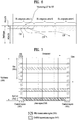
- FIGS. 1A and 1B illustrate a conventional carrier aggregation (CA)-based wireless communication system.
- LTE supports only one DL/UL frequency block
- LTE-A provides a wider frequency band by aggregating a plurality of UL/DL frequency blocks.
- Each frequency block is transmitted using a component carrier (CC).
- a CC refers to a carrier frequency (or center carrier or center frequency) of a frequency block.
- a plurality of DL/UL CCs managed by one eNB can be aggregated for one UE.
- CCs may be contiguous or non-contiguous.
- the bandwidth of each CC can be independently determined.
- Asymmetrical carrier aggregation in which the number of UL CCs differs from the number of DL CCs is possible. Even when the entire system bandwidth corresponds to N CCs, a frequency band that can be used by a specific UE can be limited to L ( ⁇ N) CCs.
- Various parameters with respect to carrier aggregation can be set cell-specifically, UE group-specifically or UE-specifically.
- Control information can be set such that the control information is transmitted and received only through a specific CC.
- a specific CC may be referred to as a primary CC (PCC) (or anchor CC) and the remaining CCs may be referred to as secondary CCs (SCCs).
- PCC primary CC
- SCCs secondary CCs Since UCI is transmitted only on the PCC, a plurality of PUCCHs is not transmitted through a plurality of UL CCs and transmission of a plurality of PUCCHs on the PCC is not permitted for UE power management. Accordingly, only one PUCCH can be transmitted in one UL subframe in a conventional CA system.
- LTE(-A) uses the concept of the cell for radio resource management.
- the cell is defined as a combination of DL resources and UL resources.
- the UL resources are not mandatory. Accordingly, the cell can be composed of DL resources only or DL resources and UL resources.
- linkage between a carrier frequency of a DL resource (or DL CC) and a carrier frequency of a UL resource (or UL CC) can be indicated by system information.
- a cell operating at a primary frequency (or on a PCC)
- a cell operating at a secondary frequency or on an SCC
- SCell secondary cell
- the PCell is used to perform initial radio resource control connection establishment or RRC connection reconfiguration.
- the PCell may refer to a cell indicated during a handover procedure.
- the SCell can be configured after RRC (Radio Resource Control) connection is established between an eNB and a UE and used to provide additional radio resources.
- the PCell and the SCell may be commonly called a serving cell.
- CC in the following description may be replaced with a serving CC, serving carrier, cell, serving cell, etc.
- FIG. 2 illustrates the structure of a radio frame.
- FIG. 2(a) illustrates the structure of a type-1 radio frame for frequency division duplex (FDD).
- a radio frame includes a plurality of (e.g., 10) subframes, and each subframe includes a plurality of (e.g., 2) slots in the time domain.
- Each subframe may have a length of 1ms and each slot may have a length of 0.5ms.
- a slot includes a plurality of OFDM/SC-FDMA symbols in the time domain and includes a plurality of resource blocks (RBs) in the frequency domain.
- RBs resource blocks
- FIG. 2(b) illustrates the structure of a type-2 radio frame for time division duplex (TDD).
- the type-2 radio frame includes 2 half frames, and each half frame includes 5 subframes.
- One subframe includes 2 slots.
- Table 1 shows uplink-downlink configurations (UL-DL Cfgs) of subframes in a radio frame in a TDD mode.
- UD-cfg is signaled through system information (e.g., a system information block (SIB)).
- SIB system information block
- SIB-cfg UD-cfg, which is set through the SIB for a TDD cell, is referred to as SIB-cfg.
- D denotes a DL subframe
- U denotes a UL subframe
- S denotes a special subframe.
- the special subframe includes a downlink pilot time slot (DwPTS), a guard period (GP), and an uplink pilot time slot (UpPTS).
- DwPTS is a time period reserved for downlink transmission
- the UpPTS is a time period reserved for uplink transmission.
- FIG. 3 illustrates a resource grid of a DL slot.
- a DL slot includes a plurality of OFDMA (or OFDM) symbols in the time domain.
- One DL slot may include 7(6) OFDMA symbols, and one resource block (RB) may include 12 subcarriers in the frequency domain.
- Each element on the resource grid is referred to as a resource element (RE).
- One RB includes 12 ⁇ 7(6) REs.
- the number N RB of RBs included in the DL slot depends on a downlink transmit bandwidth.
- the structure of a UL slot may be same as that of the DL slot except that OFDMA symbols are replaced by SC-FDMA symbols.
- FIG. 4 illustrates the structure of a DL subframe.
- up to 3(4) OFDMA symbols located in a front portion of a first slot within a subframe correspond to a control region to which a control channel is allocated.
- the remaining OFDMA symbols correspond to a data region to which a physical downlink shared chancel (PDSCH) is allocated.
- Examples of downlink control channels include a physical control format indicator channel (PCFICH), a physical downlink control channel (PDCCH), a physical HARQ indicator channel (PHICH), etc.
- the PCFICH is transmitted at a first OFDM symbol of a sub frame and carries information regarding the number of OFDMA symbols used for transmission of control channels within the subframe.
- the PHICH is a response to uplink transmission and carries a HARQ acknowledgement (ACK)/negative acknowledgement (NACK) signal.
- ACK HARQ acknowledgement
- NACK negative acknowledgement
- a PDCCH may carry a transmission format and resource allocation information of a downlink shared channel (DL-SCH), a transmission format and resource allocation information of an uplink shared channel (UL-SCH), paging information on a paging channel (PCH), system information on the DL-SCH, resource allocation information of an upper-layer control message such as a random access response transmitted on the PDSCH, a set of Tx power control commands on individual UEs within an arbitrary UE group, a Tx power control command, information on activation of a voice over IP (VoIP), etc.
- DL-SCH downlink shared channel
- UL-SCH uplink shared channel
- PCH paging information on a paging channel
- system information on the DL-SCH resource allocation information of an upper-layer control message such as a random access response transmitted on the PDSCH, a set of Tx power control commands on individual UEs within an arbitrary UE group, a Tx power control command, information on activation of a voice over IP (VoIP),
- Downlink control information is transmitted on a PDCCH.
- DCI formats 0/4 (hereinafter referred to as UL DCI formats) is defined for UL scheduling (or UL grant), and DCI format 1/1A/1B/1C/1D/2/2A/2B/2C (hereinafter referred to as DL DCI format) is defined for DL scheduling.
- the DCI format selectively includes information such as hopping flag, RB allocation information, modulation coding scheme (MCS), redundancy version (RV), new data indicator (NDI), transmit power control (TPC), demodulation reference signal (DMRS) cyclic shift, depending on its use.
- DCI formats 3/3A (referred to as TPC DCI formats hereinafter) are defined for uplink signal power control.
- the TPC DCI formats include bitmap information for a plurality of UEs, and 2-bit information (DCI format 3) or 1-bit information (DCI format 3A) in a bitmap indicates a TPC command for a PUCCH and a PUSCH of a corresponding UE.
- a plurality of PDCCHs may be transmitted within a control region.
- a UE may monitor the PDCCHs in every subframe to check a PDCCH designated to the UE.
- the PDCCH is transmitted on an aggregation of one or several consecutive control channel elements (CCEs).
- the CCE is a logical allocation unit used to provide the PDCCH with a coding rate based on a state of a radio channel.
- the CCE corresponds to a plurality of resource element groups (REGs).
- a PDCCH coding rate may be controlled according to the number of CCEs (i.e., CCE aggregation level) used for PDCCH transmission.
- the CCE includes a plurality of resource element groups (REGs).
- a format of the PDCCH and the number of PDCCH bits are determined according to the number of CCEs.
- a BS determines a PDCCH format according to DCI to be transmitted to the UE, and attaches a cyclic redundancy check (CRC) to control information.
- the CRC is masked with an identifier (e.g., radio network temporary identifier (RNTI)) according to an owner or usage of the PDCCH.
- RNTI radio network temporary identifier
- an identifier e.g., cell-RNTI (C-RNTI) of the UE may be masked to the CRC.
- a paging identifier e.g., paging-RNTI (P-RNTI)
- P-RNTI paging-RNTI
- SI-RNTI system information RNTI
- RA-RNTI random access-RNTI
- FIG. 5 illustrates an EPDCCH.
- the EPDCCH is a channel additionally introduced in LTE-A.
- a PDCCH (for convenience, legacy PDCCH or L-PDCCH) according to legacy LTE/LTE-A may be allocated to a control region (see FIG. 4 ) of a subframe.
- the L-PDCCH region means a region to which a legacy PDCCH may be allocated.
- a PDCCH may be further allocated to the data region (e.g., a resource region for a PDSCH).
- a PDCCH allocated to the data region is referred to as an E-PDCCH.
- control channel resources may be further acquired via the E-PDCCH to mitigate a scheduling restriction due to restricted control channel resources of the L-PDCCH region.
- the E-PDCCH carries DCI.
- the E-PDCCH may carry downlink scheduling information and uplink scheduling information.
- the UE may receive the E-PDCCH and receive data/control information via a PDSCH corresponding to the E-PDCCH.
- the UE may receive the E-PDCCH and transmit data/control information via a PUSCH corresponding to the E-PDCCH.
- the E-PDCCH/PDSCH may be allocated starting from a first OFDM symbol of the subframe, according to cell type.
- the non-cross-carrier scheduling (or self scheduling) scheme is the same as the legacy LTE scheduling scheme.
- a DL grant PDCCH may be transmitted in DL CC#0, and a corresponding PDSCH may be transmitted in DL CC#2.
- a UL grant PDCCH may be transmitted in DL CC#0, and a corresponding physical uplink shared channel (PUSCH) may be transmitted in UL CC#4.
- a carrier indicator field is used for cross-carrier scheduling. Whether a CIF is present in a PDCCH may be determined through higher layer signaling (e.g., RRC signaling) using semi-static and UE-specific (or UE-group-specific) schemes.
- Scheduling according to whether a CIF is set may be defined as described below.
- a BS may allocate one or more PDCCH monitoring DL CCs (hereinafter referred to as monitoring CCs (MCCs)) to a UE.
- MCCs monitoring CCs
- the UE may detect/decode a PDCCH in the MCCs. That is, if the BS schedules a PDSCH/PUSCH to the UE, a PDCCH is transmitted only in the MCCs.
- the MCCs may be set using UE-specific, UE-group-specific, or cell-specific scheme.
- the MCCs include a PCC.
- FIG. 6 illustrates cross-carrier scheduling. Although DL scheduling is illustrated in FIG. 5 , the illustrated scheme is equally applied to UL scheduling.
- 3 DL CCs may be configured for a UE, and DL CC A may be set as a PDCCH monitoring DL CC (i.e., MCC). If a CIF is disabled, each DL CC may transmit a PDCCH for scheduling its PDSCH without the CIF according to the LTE PDCCH rules. On the other hand, if a CIF is enabled, DL CC A (i.e., MCC) may transmit not only a PDCCH for scheduling its PDSCH but also PDCCHs for scheduling PDSCHs of other CCs, using the CIF. In this example, DL CC B/C transmits no PDCCH.
- MCC PDCCH monitoring DL CC
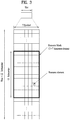
- FIG. 7 is a diagram showing the structure of an uplink subframe.
- a subframe having a length of 1 ms includes two of slots each having a length of 0.5 ms.
- the slot may include SC-FDMA symbols, the number of which is changed according to CP length.
- the slot includes seven SC-FDMA symbols in a normal CP case and includes six SC-FDMA symbols in an extended CP case.
- a resource block 503 is a resource allocation unit corresponding to 12 subcarriers in a frequency domain and one slot in a time domain.
- the structure of the uplink subframe may be divided into a control region 504 and a data region 505.
- the data region includes a PUSCH and is used to transmit a data signal such as voice.
- the control region includes a PUCCH and is used to transmit uplink control information (UCI).
- the PUCCH includes an RB pair located at both ends of the data region on a frequency axis and is hopped at a slot boundary.
- An SRS Sounding Reference Signal
- the SRS may be transmitted periodically or aperiodically at the request of an eNB. Periodic SRS transmission is defined by a cell-specific parameter and a UE-specific parameter.
- the cell-specific parameter indicates all subframe sets (referred to as cell-specific SRS subframe sets hereinafter) in which the SRS can be transmitted in a cell and the UE-specific parameter indicates a subframe subset (referred to as a UE-specific SRS subframe set hereinafter) that is actually allocated to a UE within all subframe sets.
- the PUCCH can be used to transmit the following control information.
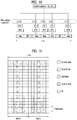
- Table 2 shows the mapping relationship between a PUCCH format (PF) and UCI in LTE(-A).
- FIG. 8 illustrates the structures of PUCCH formats 1a and 1b in a slot level.
- PUCCH formats 1a and 1b the same control information is repeated on a slot basis in a subframe.
- Each UE transmits an ACK/NACK signal in different resources configured by a different cyclic shift (CS) (frequency-domain code) and a different orthogonal cover code (OCC) (time-domain spreading code) of a computer-generated constant amplitude zero auto correlation (CG-CAZAC) sequence.
- An OCC includes a Walsh/DFT orthogonal code. If the number of CSs is 6 and the number of OCs is 3, ACK/NACK signals of 18 UEs may be multiplexed into the same physical resource block (PRB).
- PRB physical resource block
- FIG. 9 is a diagram showing PUCCH format 2.
- PUCCH format 2/2a/2b includes five QPSK data symbols and two RS symbols at a slot level. If an extended CP is configured, PUCCH format 2/2a/2b includes five QPSK data symbols and one RS symbol at a slot level. If an extended CP is configured, an RS symbol is located at a fourth SC-FDMA symbol of each slot. Accordingly, PUCCH format 2/2a/2b may carry a total of 10 QPSK data symbols. Each QPSK symbol is spread in the frequency domain by a CS and then is mapped to an SC-FDMA symbol. The RS may be multiplexed by code division multiplexing (CDM) using a CS.
- CDM code division multiplexing
- A/N is embedded in the second RS of each slot (e.g., A/N is multiplied by the RS) in PUCCH format 2a/2b.
- A/N and CSI are joint-coded and then transmitted through PUCCH format 2.
- FIG. 10 illustrates the structure of PUCCH format 3 in a slot level.
- PUCCH format 3 is used to transmit a plurality of ACK/NACK information, and information such as CSI and/or SR may be transmitted together.
- one symbol sequence is transmitted over the frequency domain, and OCC-based time-domain spreading is applied to the symbol sequence.
- Control signals of a plurality of UEs may be multiplexed into the same RB using OCCs.
- 5 SC-FDMA symbols i.e. a UCI data part
- the symbol sequence ⁇ d1, d2, ... ⁇ maybe a modulation symbol sequence or a codeword bit sequence.
- the symbol sequence ⁇ d1, d2, ... ⁇ may be generated by performing joint coding (e.g., Reed-Muller coding, tail-biting convolutional coding, etc.), block-spreading, and SC-FDMA modulation on a plurality of ACK/NACK information.
- joint coding e.g., Reed-Muller coding, tail-biting convolutional coding, etc.
- block-spreading e.g., SC-FDMA modulation
- FIG. 11 illustrates a method for transmitting UCI on a PUSCH.
- a subframe which requires UCI transmission has PUSCH assignment, UCI may be transmitted on a PUSCH (PUSCH piggyback).
- PUSCH data i.e., UL-SCH data
- information e.g, coded symbol
- ACK/NACK is inserted into part of SC-FMDA resources to which the UL-SCH data is mapped through puncturing.
- UCI can be scheduled to be transmitted on a PUSCH without the UL-SCH data.
- a UE When a UE needs to transmit a PUCCH in a cell-specific SRS subframe set, the UE does not use the last SC-FDMA symbol of the second slot to transmit the PUCCH in order to protect the SRS thereof/SRSs of other UEs.
- a PUCCH format in which all SC-FDMA symbols of a subframe are used for PUCCH transmission is referred to as a normal PUCCH format and a PUCCH format in which the last SC-FDMA symbol of the second slot is not used for PUCCH transmission is referred to as a shortened PUCCH format.
- PUSCH data i.e. UL-SCH data
- coded symbol is rate-matching in consideration of the quantity of resource of the last SC-FDMA symbol.
- a PUSCH, which is transmitted using all SC-FDMA symbols of a subframe is referred to as a normal PUSCH and a PUSCH, which is transmitted without using the last SC-FDMA symbol of the second slot, is referred to as a rate-matched PUSCH.
- FIGS. 12 to 17 illustrate the ACK/NACK transmission procedure and the signal transmission timing thereof on the basis of a TDD CC (or cell) and timing for an FDD CC (or cell) will be additionally described.
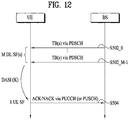
- FIGS. 12 and 13 illustrate ACK/NACK (A/N) timing (or HARQ timing).
- a UE may receive one or more PDSCH signals in M DL subframes (SFs) (S502_0 to S502_M-1) (M ⁇ 1).
- Each PDSCH signal may include one or more (e.g., 2) transport blocks (TBs) according to a transmission mode.
- a PDCCH signal indicating SPS release may also be received in steps S502_0 to S502_M-1.
- the UE transmits an ACK/NACK in one UL subframe corresponding to the M DL subframes through a procedure for ACK/NACK transmission (e.g.
- the ACK/NACK includes acknowledgement information on the PDSCH signal and/or SPS release PDCCH signal of steps S502_0 to S502_M-1.
- the ACK/NACK is basically transmitted on a PUCCH, if there is PUSCH transmission at ACK/NACK transmission timing, the ACK/NACK is transmitted on a PUSCH. If a plurality of CCs is configured for the UE, the PUCCH is transmitted only in a PCC, and the PUSCH is transmitted in a scheduled CC.
- a variety of PUCCH formats shown in Table 2 may be used for ACK/NACK transmission.
- a variety of schemes such as ACK/NACK bundling, ACK/NACK channel selection (CHSel), etc. may be used to reduce the number of ACK/NACK bits to be transmitted.
- M 1 in FDD and M is an integer equal to or greater than 1 in TDD.
- TDD Time Division Duplex Time Division Duplex
- DASI Downlink Association Set Index
- Table 3 shows a DASI (K: ⁇ k 0 ,k 1 ,...k M-1 ⁇ ) defined in LTE(-A).
- DASI K: ⁇ k 0 ,k 1 ,...k M-1 ⁇
- a PDCCH that indicates PDSCH transmission and/or SPS (Semi-Persistent Scheduling) release is present in subframe n-k (k ⁇ K)
- a UE transmits ACK/NACK in subframe n.
- a UE needs to transmit one or more A/N signals for DL transmission (e.g., PDSCH), received through M DL SFs, through one UL SF.
- A/N signals for DL transmission e.g., PDSCH
- M DL SFs e.g., M DL SFs
- UL SF e.g., DL SFs
- Methods for transmitting A/N for a plurality of DL SFs through one UL SF are will now be described.
- an ACK/NACK transmission resource scheduled by a DL grant L-PDCCH can be determined as a PUCCH resource linked to a specific ECCE index (e.g., minimum ECCE index) corresponding to an ECCE constituting the DL grant L-PDCCH (implicit PUCCH resource).
- n (1) PUCCH indicates a resource index of PF1 for ACK/NACK/DTX transmission
- N (1) PUCCH indicates a signaling value received from a higher layer (e.g., Radio Resource Control (RRC))
- n CCE indicates a smallest value from among CCE indices used for L-PDCCH transmission.
- RRC Radio Resource Control
- a CS Cyclic Shift
- an OC Orthogonal Code
- PRB Physical Resource Block
- PF3 resource index from among a plurality of PF3 resource indices (n (3) PUCCH ) allocated by a higher layer (e.g., RRC) can be indicated by an ARI (ACK/NACK Resource Indicator) of the DL grant L-PDCCH (explicit PUCCH resource).
- the ARI is transmitted through a TPC field of an L-PDCCH that schedules a PDSCH of an SCell.
- An OC and a PRB for PF3 are obtained from n (3) PUCCH .
- an ACK/NACK transmission resource for DL data scheduled by a DL grant EPDCCH can be determined as a PUCCH resource linked to a specific ECCE index (e.g., minimum ECCE index) corresponding to an ECCE constituting the DL grant EPDCCH or an ECCE index obtained by adding a specific offset value to the specific ECCE index.
- An ACK/NACK feedback transmission resource can be determined as a PUCCH resource linked to a specific ECCE index (e.g., minimum ECCE index) corresponding to an ECCE constituting the DL grant EPDCCH or an ECCE index obtained by adding a specific offset value to the specific ECCE index.
- the specific offset value can be determined by a value, which is directly signaled through an ARO (ACK/NACK Resource Offset) field in the DL grant EPDCCH, and/or a value designated per AP (Antenna Port).
- ARO ACK/NACK Resource Offset
- information signaled through the TPC field and the ARO field in the DL grant EPDCCH according to frame structure type (e.g., FDD or TDD) and feedback transmission method (e.g., PF3 or CHsel) can be configured as follows.
- TPC value an offset value added when an implicit PUCCH index is determined is defined as "ARO value”
- ARO value an offset value added when an implicit PUCCH index is determined
- ARI value an ARI that indicates a specific one of a plurality of PF3 indices or a plurality of PF1 indices (groups) allocated through RRC is defined as "ARI value”.
- a fixed value e.g., "0" that is inserted (for virtual CRC or the like) without containing no information is defined as "fixed value”.
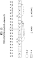
- FIG. 13 illustrates A/N timing applied to a CC having UL-DL Cfg #1.
- SF#0 to SF#9, and SF#10 to SF#19 correspond to radio frames.
- the numeral in a box denotes a DL subframe associated with a UL subframe.
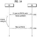
- FIGS. 14 and 15 illustrate UL grant (UG)/PHICH-PUSCH timing.
- a PUSCH may be transmitted in response to a PDCCH (UL grant) and/or PHICH (NACK).
- a UE may receive a PDCCH (UL grant) and/or PHICH (NACK) (S702).
- the NACK corresponds to an ACK/NACK response to previous PUSCH transmission.
- the UE may initially transmit or retransmit one or more TBs on a PUSCH after k subframes through a procedure for PUSCH transmission (e.g., TB coding, TB-CW swapping, PUSCH resource allocation, etc.) (S704).
- a procedure for PUSCH transmission e.g., TB coding, TB-CW swapping, PUSCH resource allocation, etc.
- This example assumes a normal HARQ operation in which a PUSCH is transmitted once.
- a PHICH/UL grant corresponding to PUSCH transmission is present in the same subframe.
- a UL grant/ PHICH corresponding to PUSCH transmission may be present in different subframes.
- Table 4 shows an uplink association index (UAI) (k) for PUSCH transmission in LTE(-A).
- UAI uplink association index
- Table 4 shows the interval between a DL subframe in which a PHICH/UL grant is detected, and a UL subframe associated with the DL subframe. Specifically, if a PHICH/UL grant is detected in subframe n, a UE may transmit a PUSCH in subframe n+k.
- UAI(i.e., k) 4.
- FIG. 15 illustrates PUSCH transmission timing when UL-DL Cfg #1 is set.
- SF#0 to SF#9, and SF#10 to SF#19 correspond to radio frames.
- the numeral in a box denotes a UL subframe associated with a DL subframe.
- FIGS. 16 and 17 illustrate PUSCH-UL grant (UG)/PHICH timing.
- a PHICH is used to transmit a DL ACK/NACK.
- the DL ACK/NACK is a response to UL data (e.g., PUSCH) and refers to an ACK/NACK transmitted in downlink.
- a UE transmits a PUSCH signal to a BS (S902).
- the PUSCH signal is used to transmit one or more (e.g., 2) TBs according to a transmission mode.
- the BS may transmit an ACK/NACK to the UE on a PHICH after k subframes through a procedure for ACK/NACK transmission (e.g., ACK/NACK generation, ACK/NACK resource allocation, etc.) (S904).
- the ACK/NACK includes acknowledgement information on the PUSCH signal of step S902.
- the BS may transmit a UL grant PDCCH for retransmitting the PUSCH, to the UE after k subframes (S904).
- This example assumes a normal HARQ operation in which a PUSCH is transmitted once.
- a UL grant/PHICH corresponding to PUSCH transmission may be transmitted in the same subframe.
- a UL grant/ PHICH corresponding to PUSCH transmission may be transmitted in different subframes.
- Table 5 shows PHICH timing defined for TDD.
- a UE determines corresponding PHICH resources in subframe #(n+k PHICH ).
- k PHICH 4.
- TDD UL-DL Configuration UL subframe index n 0 1 2 3 4 5 6 7 8 9 0 4 7 6 4 7 6 1 4 6 4 6 2 6 6 3 6 6 6 4 6 6 5 6 6 4 6 6 4 7
- FIG. 17 illustrates UL grant/PHICH transmission timing when UL-DL Cfg #1 is set.
- SF#0 to SF#9, and SF#10 to SF#19 correspond to radio frames.
- the numeral in a box denotes a DL subframe associated with a UL subframe.
- a UE when a UE transmits an ACK/NACK signal to a BS, if the UE has missed a part of PDCCH(s) transmitted from the BS in a period of a plurality of subframes, the UE does not even know that a PDSCH corresponding to the missed PDCCH was transmitted to the UE and thus an error may occur in generating ACK/NACK.
- a DL grant PDCCH/SPS release PDCCH for a TDD CC includes a DAI field (i.e., DL DAI field).
- the value of DL DAI field designates an cumulative value (i.e., count) of PDCCH(s) corresponding to PDSCH(s) and PDCCH(s) indicating downlink SPS release to a current subframe within DL subframe(s) n-k (k ⁇ K).
- PDSCHs transmitted in a period of 3 DL subframes are sequentially indexed (i.e., sequentially counted) and the index (or count) is delivered on a PDCCH for scheduling the PDSCHs.
- the UE may determine whether a previous PDCCH is appropriately received, by checking DAI information of the PDCCH.
- FIG. 18 illustrates an ACK/NACK transmission procedure using a DL DAI.
- This example assumes a TDD system configured by 3 DL subframes: 1 UL subframe. It is assumed for convenience that a UE transmits ACK/NACK using PUSCH resources.
- ACK/NACK is transmitted on a PUSCH, 1-bit or 2-bit bundled ACK/NACK is transmitted.
- the UE may know that the second PDCCH is missed. In this case, the UE may process an ACK/NACK response to the second PDCCH as a NACK (or NACK/DTX).
- the UE may not recognize that the last PDCCH is missed (i.e., DTX).
- a UL grant PDCCH also includes a DAI field (i.e., UL DAI field).
- the UL DAI field is a 2-bit field and includes information about the number of scheduled PDCCHs.
- Table 6 shows values (V DL DAI , V UL DAI ) indicated by a DAI field in a DCI format.
- V DL DAI denotes a DL DAI value
- V UL DAI denotes a UL DAI value.
- V DL DAI denotes the value of DAI field in DCI format 1/1A/1B/1D/2/2A/2B/2C/2D for UL-DL Cfgs #0 to #6.
- V UL DAI denotes the value of DAI field in DCI format 0/4 (i) if one CC (or cell) having UL-DL Cfgs #1 to #6 is configured, or (ii) if a UE is configured not to use PUCCH format 3.
- Table 7 shows a value (W UL DAI ) indicated by a DAI field in DCI format 0/4.
- W UL DAI denotes the value of DAI field in DCI format 0/4 (i) if a plurality of CCs (or cells) having UL-DL Cfgs #1 to #6 are configured, or (ii) if one CC (or cell) having UL-DL Cfgs #1 to #6 is configured and a UE is configured to use PUCCH format 3.
- DL DAI is referred to as V
- UL DAI is referred to as W.
- DAI is used in various ways in an ACK/NACK transmission procedure.
- a DAI may be used for DTX detection as illustrated in FIG. 16 , or used in an ACK/NACK payload generating procedure (e.g., determination of the size of ACK/NACK payload and the location of ACK/NACK information in the ACK/NACK payload) or ACK/NACK resource allocation procedure.
- DTX detection using a DAI a description is now given of DTX detection using a DAI.
- V DAI UL ⁇ U DAI + N SPS ⁇ 1 mod 4 + 1 it is assumed that at least one DL assignment is missed (i.e., DTX occurs), and a UE generates a NACK of all codewords according to a bundling procedure.
- U DAI denotes a total number of DL grant PDCCHs and SPS release PDCCHs detected in subframe n-k (k ⁇ K) (see Table 3).
- N SPS denotes the number of SPS PDSCHs and is 0 or 1.
- ACK/NACK payload generation using a DAI It is assumed for convenience that PUCCH format 3 is configured.
- ACK/NACK payloads for PUCCH format 3 are configured per cell, and arranged in the order of cell indices.
- HARQ-ACK feedback bits for a c-th serving cell are given as o c ,0 ACK o c ,0 ACK , ... , o c , O c ACK ⁇ 1 ACK (c ⁇ 0).
- O ACK c denotes the number of bits (i.e., size) of HARQ-ACK payload of the c-th serving cell.
- O ACK c B DL c .
- B DL c M.
- M denotes the number of elements in set K defined in Table 3.
- W UL DAI denotes a value indicated by a UL DAI field in a UL grant PDCCH (Table 7), and is simply referred to as W.
- B c DL W DAI UL + 4 ⁇ U ⁇ W DAI UL / 4 ⁇ .
- U denotes a maximum value among Ucs
- Uc denotes a total number of PDSCH(s) received and PDCCHs indicating (downlink) SPS release in subframe n-k in the c-th serving cell.
- Subframe n is a subframe for transmitting the HARQ-ACK feedback bits.
- ⁇ ⁇ denotes a ceiling function.
- the location of each ACK/NACK in HARQ-ACK payload of the serving cell is given as o c , DAI k ⁇ 1 ACK .
- DAI(k) denotes a DL DAI value of a PDCCH detected in DL subframe n-k.
- the location of each ACK/NACK in HARQ-ACK payload of the serving cell is given as o c ,2 ⁇ DAI k ⁇ 2 ACK and o c ,2 ⁇ DAI k ⁇ 1 ACK .
- o c ,2 ⁇ DAI k ⁇ 2 ACK denotes HARQ-ACK for codeword
- o c ,2 ⁇ DAI k ⁇ 1 ACK denotes HARQ-ACK for codeword 1.
- Codeword 0 and codeword 1 may respectively correspond to TB0 and TB1, or TB1 and TB0 according to swapping. If PUCCH format 3 is transmitted in a subframe configured for SR transmission, PUCCH format 3 transmits ACK/NACK bits and a 1-bit SR together.
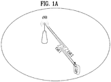
- LTE-A assume that aggregation (that is, CA) of a plurality of cells is supported and a plurality of cells aggregated for one UE is managed by one eNB (intra-site CA) (see, FIG. 1 ).
- intra-site CA since all cells are managed by one eNB, signaling related to various RRC configurations/reports and MAC commands/messages may be performed via any one of all aggregated cells. For example, signaling involved in a procedure of adding or releasing a specific SCell to or from a CA cell set, a procedure of changing a transmission mode (TM) of a specific cell, a procedure of performing radio resource management (RRM) measurement reporting associated with a specific cell, etc.
- TM transmission mode
- RRM radio resource management
- a per-cell power headroom report (PHR) for UL power control, a per-timing advanced group (TAG) timing advance command (TAC) for UL synchronization control, etc. may be signaled via any cell of the CA cell set.
- a plurality of cells having small coverage may be deployed in a cell (e.g., a macro cell) having large coverage, for traffic optimization.
- a macro cell and a micro cell may be aggregated for one UE, the macro cell may be mainly used for mobility management (e.g., PCell) and the micro cell may be mainly used for throughput boosting (e.g., SCell).
- the cells aggregated for one UE may have different coverages and may be respectively managed by different eNBs (or nodes (e.g., relays) corresponding thereto) which are geographically separated from each other (inter-site CA).
- FIG. 19 is a diagram showing inter-site carrier aggregation (CA).
- CA inter-site carrier aggregation
- BH backhaul
- a wired X2 interface or a wireless backhaul link e.g., a wired X2 interface or a wireless backhaul link
- a PCell e.g., CC1 (group) and an SCell (e.g., CC2) (group) aggregated for one UE are respectively managed by eNB-1 and eNB-2
- the eNB that is, eNB-1 for managing the PCell is responsible for managing/performing an RRC function associated with the UE corresponding thereto.
- eNB-2 may deliver the RRM measurement report to eNB-1 via the BH.
- RRM radio resource management
- eNB-1 sends an RRC reconfiguration command for releasing the SCell from the CA cell set to the UE via the PCell (e.g., a PDSCH)
- the UE may transmit a confirmation response to the RRC reconfiguration command via the SCell (e.g., a PUSCH) instead of the PCell.
- eNB-2 may deliver the confirmation response to eNB-1 via the BH, etc. Accordingly, in inter-site CA, considerable latency may be caused in an inter-cell (that is, inter-eNB) signaling procedure. Thus, misalignment between the eNB and the UE for CA cell set interpretation may occur and stable/efficient cell resource management and control may not be facilitated.
- inter-cell that is, inter-eNB
- per-cell PHRs of all cells may be transmitted via the PCell (e.g., the PUSCH).
- eNB-1 for managing the PCell
- eNB-2 for managing the SCell
- eNB-2 may deliver all PHRs or a PHR corresponding to the PCell to eNB-1 via the BH, etc.
- stable/efficient UL power control and adaptive UL data scheduling/transmission based thereon may not be facilitated due to latency caused by inter-eNB signaling.
- DL/UL data scheduling and UCI may be performed per cell (group) belonging to the same eNB.
- a PCell and an SCell which are aggregated for one UE, respectively belong to eNB-1 and eNB-2
- a DL/UL grant which schedules DL/UL data transmitted through the PCell, and ACK/NACK feedback for the DL/UL data
- a DL/UL grant which schedules DL/UL data transmitted through the SCell, and ACK/NACK feedback for the DL/UL data can be transmitted through the SCell.
- aperiodic CSI (a-CSI)/periodic CSI (p-CSI) reports and SR signaling with respect to the PCell can be transmitted through the PCell
- CSI report and SR signaling with respect to the SCell can be transmitted through the SCell.
- simultaneous transmission of multiple PUCCHs includes simultaneous transmission of multiple PUCCHs in multiple cells (i.e. simultaneous transmission of PUCCHs for respective cells).
- a parameter that indicates whether simultaneous transmission of PUCCHs is permitted is defined as "multi-PUCCH".
- the multi-PUCCH When the multi-PUCCH is set to ON, a UE can perform simultaneous transmission of multiple PUCCHs within one UL subframe.
- the multi-PUCCH is set to OFF, the UE cannot perform simultaneous transmission of multiple PUCCHs within one UL subframe. That is, when the multi-PUCCH is OFF, simultaneous transmission of multiple PUCCHs within one UL subframe is not permitted and only transmission of a single PUCCH can be permitted in one UL subframe (in a single cell).
- whether to permit simultaneous transmission of an SRS and UCI can be independently set per cell or cell group through higher layer signaling (e.g., RRC signaling).
- RRC signaling e.g., RRC signaling.
- the shortened PUCCH format can be used when simultaneous transmission of the SRS and UCI is permitted, whereas the normal PUCCH format can be used when simultaneous transmission of the SRS and UCI is not permitted.
- PUCCH transmission per cell can be configured such that PUCCH transmissions for respective cells are performed at different timings, that is, in a TDM manner in the case of multi-PUCCH OFF.
- UCI transmission timing (e.g., ACK/NACK transmission timing) may need to be changed according to setting of PUCCH transmission timing per cell.
- the UCI transmission timing per cell may depend on a frame structure type (i.e., FDD or TDD) of a cell constituting CA, a subframe configuration form (e.g., UD-cfg) and the like.
- a description will be given of an ACK/NACK transmission timing setting method and an ACK/NACK feedback configuration/transmission method according to CA on the basis of ACK/NACK.
- a cell group includes one or more cells. Accordingly, a cell group can be composed of only one cell or a plurality of cells. Respective cell groups may belong to different eNBs. Specifically, a PCell group and an SCell group can be aggregated for one UE, the PCell group can belong to eNB-1 (e.g. macro eNB) and the SCell group can belong to eNB-2 (e.g. micro eNB).
- the PCell group refers to a cell group including a PCell.
- the PCell group is composed of the PCell alone or includes the PCell and one or more SCells.
- the SCell group refers to a cell group composed of SCells only and includes one or more SCells. However, this is exemplary and the present invention can be equally/similarly applied to a case in which three or more cell groups (e.g. one PCell group and two or more SCell groups) are aggregated for one UE.
- the present invention provides methods for setting ACK/NACK transmission timing and configuring/transmitting ACK/NACK feedback when multiple cell groups are aggregated for one UE and UCI transmission is performed per cell group (i.e., when UCI with respect to/corresponding to each cell group is transmitted through a specific cell within the corresponding cell group) (or in the case of PUCCH transmission per cell). Accordingly, although the following description focuses on a case in which multiple cell groups belonging to different eNBs are aggregated for one UE, this is exemplary and the present invention can also be equally/similarly applied to a case in which multiple cell groups belonging to one eNB are aggregated for one UE.
- a PUCCH may be transmitted through a PCell in the PCell group and the PUCCH may be transmitted through a specific SCell in the SCell group according to the present invention.
- the SCell configured to transmit the PUCCH in the SCell group is referred to as an ACell.
- the PCell group and the SCell group may belong to different eNBs (e.g. PCell - macro eNB, SCell - micro eNB) or
- the PCell group and the SCell group may belong to the same eNB.
- the ACell can be determined as a cell having a lowest cell index (e.g., ServCell index or SCell index) from among cells configured (as scheduling cells) to transmit a PDCCH/EPDCCH (through cross-CC scheduling) in one cell group.
- a lowest cell index e.g., ServCell index or SCell index
- the present invention proposes setting of the starting index of implicit PUCCH resources linked to an EPDCCH set (ECCE resources constituting the same) or a PUCCH index offset by which the starting index can be inferred for an EPDCCH set configured in the ACell (distinguished from a conventional scheme in which the starting index or the PUCCH index offset is set only for an EPDCCH set configured in the PCell).
- the present invention proposes provision/activation of signaling information (e.g. TPC/ARO/ARI values), which is necessary to control/determine an A/N transmission PUCCH resource through a specific field (e.g. TPC/ARO) within a DL grant EPDCCH, even for a DL grant EPDCCH corresponding/transmitted to/in the ACell.
- signaling information e.g. TPC/ARO/ARI values
- information signaled through the TPC/ARO field within the DL grant EPDCCH can be configured per cell according to frame structure type (FDD or TDD) and A/N feedback transmission method (PF3 or CHsel).
- an SCell can refer to a normal SCell other than the PCell and the ACell.
- A/N feedback for an arbitrary cell group is configured to be transmitted through a specific ACell (here, the cell group can include the ACell), ARIs (to be applied to the same A/N transmission timing) signaled through all DL grant EPDCCHs and/or all DL grant PDCCHs (scheduling the corresponding cell group and/or transmitted through the corresponding cell group) for the corresponding cell group may have the same value. That is, a UE can operate on the assumption that ARIs in all DL grant PDCCHs have the same value.
- an ARI can have an independent value per cell group.
- an ARI with respect to a cell group to which a PCell belongs and an ARI with respect to a cell group to which an ACell belongs can have the same value or different values (for the same A/N transmission timing).
- an A/N payload in PUCCH format 3 can be configured in such a manner that an A/N bit corresponding to the ACell is placed at the side of the MSB.
- an ACK/NACK feedback transmission scheme using "PUCCH format 3” is referred to as “PF3” and an ACK/NACK feedback transmission scheme according to "PUCCH format 1b with channel selection” is referred to as "CHsel”.
- an ACK/NACK feedback transmission scheme using "PUCCH format 1a/1b” is referred to as "PF1".
- the PDCCH includes both the L-PDCCH and the EPDCCH.
- A/N timing refers to the relationship between DL data (that is, a PDSCH or an SPS release PDCCH) timing and HARQ-ACK timing corresponding thereto (refer to FIGS. 12 and 13 ). Since a special SF can be regarded to be the same as a DL SF from the viewpoint of A/N, and thus the DL SF includes both the DL SF and the special SF with respect to A/N.
- UCI transmission cells i.e., a PCell and an ACell
- a cell can be extended to a cell group.
- A/N transmission method based on TDM of cells in CA of FDD cells is considered as follows.
- A/N corresponding to cell 1 may be transmitted through cell 1 in N UL SFs (e.g., SF #k to SF #(k+N-1)) (referred to as First part_ul, hereinafter) and A/N corresponding to cell 2 may be transmitted through cell 2 in the next M UL SFs [e.g., SF #(k+N) to SF #(k+N+M-1)] (referred to as Second part_ul, hereinafter) (N ⁇ 1, M ⁇ 1).
- DL data scheduling in DL SFs i.e., SF #(k+N-d F ) to SF #(k+N+M-1-d F )
- Second part_dl DL data scheduling in DL SFs
- First part ul and Second part ul are configured as above.
- the first DL SF (i.e., SF #(k+N-d F )) of Second part_dl is defined as "last SF”
- First part_dl + Last SF i.e., SF #(k-d F ) to SF #(k+N-d F )
- Entire duration i.e., SF #(k-d F ) to SF #(k+N-d F )
- First part ul and Second part ul may be configured as a plurality of non-consecutive SFs.
- a UE may operate on the assumption that DL data scheduling/transmission with respect to cell 2 is not permitted or present in First part dl (i.e., DL SF #(k-d F ) to DL SF #(k+N-1-d F )). For example, in DL SF #(k-d F ) to DL SF #(k+N-1-d F ), the UE may not perform monitoring (e.g. blind decoding) for a PDCCH carrying a DL DCI format, which schedules DL data of cell 2, or may ignore the PDCCH carrying the DL DCI format (may not perform PDSCH decoding) when the PDCCH is detected.
- monitoring e.g. blind decoding
- the UE can perform normal operation (e.g., PDCCH monitoring and PUSCH transmission) for a UL DCI format. Accordingly, A/N feedback and timing corresponding to First part dl may not be defined/set in cell 2. Therefore, only A/N corresponding to DL data, received in Second part_dl (i.e., DL SF #(k+N-d F ) to DL SF #(k+N+M-1-d F )) through cell 2, can be transmitted in Second part_ul (i.e., UL SF #(k+N) to UL SF #(k+N+M-1)) through cell 2 on the basis of A/N timing.
- Second part_ul i.e., UL SF #(k+N) to UL SF #(k+N+M-1)
- the UE may apply PF3 or CHsel based on multiple SFs to A/N corresponding to DL data received in First part_dl + Last SF (i.e., SF #(k-d F ) to SF #(k+N-1-d F ) + SF #(k+N-d F )) through cell 2.
- PF3 or CHsel based on multiple SFs refer to a method of transmitting multiple A/N information on DL data received in multiple SFs through PF3 or using CHsel.
- multiple A/N information corresponding to First part_dl + Last SF can be transmitted in the first UL SF (i.e., UL SF #(k+N)) of Second part_ul through cell 2 on the basis of PF3/CHsel.
- A/N corresponding to the DL data can be transmitted using an implicit PF1 resource linked to a DL grant PDCCH that has scheduled the DL data (i.e., single A/N fallback).
- A/N feedback corresponding to the entire duration can be transmitted using a PF3 resource indicated by a DL grant PDCCH that has scheduled the DL data.
- a TPC command for PUCCH power control may be signaled on a DL grant PDCCH that schedules the last SF and an ARI value indicating the PF3 resource may be signaled on a DL grant PDCCH that schedules First part dl.
- ARI values can be set to the same value.
- A/N bits are arranged in PF3 in SF order (e.g., A/N bit(s) corresponding to a preceding or lagging SF(s) is placed at the side of the MSB).
- cell 2 is a specific cell (e.g., a PCell or ACell) in a cell group composed of a plurality of cells
- a specific cell e.g., a PCell or ACell
- A/N corresponding to the DL data can be transmitted using an implicit PF1 resource linked to a DL grant PDCCH that has scheduled the DL data.
- A/N can be transmitted using PF3 as described above.
- ARI values indicating PF3 resources can be signaled on all DL grant PDCCHs that schedule First part dl and the last SF.
- an implicit PF1 resource linked to a DL grant PDCCH that schedules the corresponding SF can be allocated.
- An explicit PF1 resource reserved through RRC signaling can be allocated as a PUCCH resource corresponding to First part dl.
- a TPC command for PUCCH power control can be signaled on the DL grant PDCCH that schedules the last SF, and an ARI value indicating the explicit PF1 resource can be signaled in a DL grant PDCCH that schedules First part_dl.
- A/N may be arranged in A/N state in SF order (e.g., A/N corresponding to a preceding or lagging SF is placed at the side of the MSB).
- SF bundling and/or CW bundling can be applied to A/N corresponding to DL data received in the entire duration (i.e., SF #(k-d F ) to SF #(k+N-d F ) through cell 2.
- SF bundling refers to application of A/N bundling to all or some DL subframes in each DL CC.
- CW bundling refers to application of A/N bundling per DL CC in each DL SF.
- A/N bundling refers to a logic-AND operation of A/N results.
- bundling based A/N feedback can be transmitted in UL SF #(k+N) through cell 2.
- Bundled A/N feedback can be transmitted using an implicit PF1 resource linked to a DL grant PDCCH that schedules DL data lastly received in the entire duration or an explicit PF1 resource reserved through RRC signaling.
- a DAI indicating a time sequence (or accumulation value) of scheduled DL data (or DL grants) and/or an ARI value indicating the explicit PF1 resource can be signaled on a DL grant PDCCH that schedules the entire duration.
- A/N corresponding to the entire duration can be transmitted in a UL SF (i.e., Last SF + d F ) corresponding to the last SF through PF3, CHsel, bundling and the like in each cell.
- timing advance (TA) values i.e., UL transmission timing of a UL radio frame with respect to DL radio frame
- TA timing advance
- A/N transmission signals e.g., PUCCHs
- PUCCHs Physical Uplink Control Channel
- a UL operation frequency needs to be dynamically switched between neighboring UL SFs in order to apply the TDM-based A/N (PUCCH) transmission method between cells.
- A/N transmission signals e.g., PUCCHs
- PUCCHs PUCCHs
- the present invention proposes provision of an SF gap between contiguously configured A/N transmission timings of different cells in order to maintain single carrier property of UL signals.
- the SF gap refers to an SF in which UL transmission is limited.
- transmission of at least one of UCI (e.g., A/N), a PUCCH, a PUSCH, an SRS and a PRACH may not be performed/defined in the SF gap.
- the SF gap can be designated/set as an SF in which transmission of UCI (e.g. A/N) and/or a PUCCH is not performed/defined, or as an SF in which UL data and/or PUSCH scheduling/transmission are not performed/defined (in the case of a UL non-CA UE).
- A/N feedback corresponding to cell 1 can be transmitted in N UL SFs (e.g., SF #k to SF #(k+N-1)) (First part_ul) through cell 1, the following UL SF (e.g., SF #(k+N)) can be set as an SF gap, A/N feedback corresponding to cell 2 can be transmitted in the following M UL SFs (e.g., SF #(k+N+1) to SF #(k+N+M)) (Second part_ul) through cell 2, and the next UL SF (e.g., SF #(k+N+M+1)) can be set as an SF gap.
- N UL SFs e.g., SF #k to SF #(k+N-1)
- M UL SFs e.g., SF #(k+N+1) to SF #(k+N+M)
- the next UL SF e.g., SF #(k
- the aforementioned proposed method (Sol 1 to 3) can be applied in a state that a DL SF corresponding to an SF gap has been added as the last SF that constitutes First part_dl or Second part_dl.
- DL SF #(k+N-d F ) can be added to First part-dl and DL SF #(k+N+M+1-d F ) can be added to Second part-dl.
- the aforementioned SF gap based method can be equally/similarly applied to an FDD cell when the FDD cell and a TDD cell are aggregated.
- the following two methods are proposed for A/N transmission based on TDM of cells when an FDD cell and a TDD cell are aggregated.
- A/N feedback configuration/transmission can be performed using A/N timing defined in UD-cfg of the TDD cell.
- an SF interval which is set to A/N transmission SFs in the TDD cell, can be regarded as an SF interval that is not set to A/N transmission SFs, that is, First part ul in the FDD cell and Sol 1 to 3 can be applied.
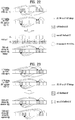
- FIG. 21 illustrates an A/N transmission method according to this method. Referring to FIG. 21 , A/N timing according to SIB-cfg is applied to the TDD cell, and Sol 2 is applied to the FDD cell in a state that a UL SF interval of the TDD cell is regarded as First part_ul.
- A/N timing defined in UD-cfg of the TDD cell can be applied.
- the original A/N timing based on FDD A/N delay d F can be applied.
- A/N for both the FDD cell and the TDD cell can be transmitted in an SF designated as A/N transmission timing of the TDD cell through the TDD cell, and only A/N for the FDD cell can be transmitted in the remaining SFs (i.e., SFs which do not correspond to A/N transmission timing of the TDD cell) through the FDD cell.
- DL superset-cfg refers to UD-cfg (i.e., UD-cfg in which a larger number of DL SFs, which includes DL SFs of SIB-cfg, than those of SIB-cfg are configured) in which DL SFs are configured for a superset of DL SFs that constitute SIB-cfg (refer to Table 1).
- DL superset-cfg is equivalent to UL subset-cfg.
- UL subset-cfg refers to UD-cfg (i.e. UD-cfg in which a smaller number of UL SFs, which are included in UL SFs of SIB-cfg, than those of SIB-cfg are configured) in which UL SFs are configured for a superset of UL SFs that constitute SIB-cfg.
- an SF interval which is set to an A/N transmission SF in DL superset-cfg, is regarded as First part ul and Sol 1 to 3 can be applied.
- FIG. 22 illustrates an A/N transmission according to this method.
- A/N timing according to DL superset-cfg is applied to the TDD cell
- Sol 2 is applied to the FDD cell in a state that a UL SF interval according to DL superset-cfg is regarded as First part_ul.
- SIB-cfg of the TDD cell is UD-cfg #1
- A/N feedback configuration/transmission can be performed using A/N timing defined in one of UD-cfg #2, #4 and #5 which are DL superset-cfg of UD-cfg #1 in the case of the TDD cell.
- Sol 1 to 3 can be applied to the FDD cell by regarding SF #2 and SF #7 configured as A/N transmission SFs in UD-cfg #2 as First part_ul.
- A/N timing is applied to the TDD cell based on Alt 1-2
- application of A/N timing of DL superset-cfg (and execution of DL data detection/reception operation) and corresponding A/N signal/bit configuration can be set/defined only for DL SFs (i.e., DL SFs (and S SF) in SIB-cfg) of the TDD cell.
- A/N timing of DL superset-cfg (and DL data detection/reception operation) and corresponding A/N signal/bit configuration may not be set/applied for UL SFs (i.e., UL SFs in SIB-cfg) of the TDD cell.
- UL SFs i.e., UL SFs in SIB-cfg
- Kc includes values of k sp ⁇ K sp and specifically includes only a k sp value that allows subframe #n-k sp to actually correspond to a DL SF or an S SF in the TDD cell.
- K sp indicates a DASI value of DL superset-cfg (refer to Table 3).
- A/N timing defined in DL superset-cfg may differ from A/N timing defined in SIB-cfg of the TDD cell. Accordingly, implicit PF1 linkage based on A/N timing of SIB-cfg (i.e., implicit PF1 resource indices linked to DL SFs) may not be applied. To solve this problem, only explicit PF1 resources reserved through RRC signaling may be used for CHsel.
- PF3 when PF3 is set for A/N transmission, if only DL data corresponding to single A/N fallback (i.e., data corresponding to a PDCCH having a DAI initial value (e.g., 1) or an SPS release PDCCH having the DAI initial value (e.g., 1)) is received, explicit PF1 resources reserved through RRC signaling can be used for A/N transmission.
- ARIs indicating explicit PF1 resources can be signaled through all DL grant PDCCHs.
- an ARI indicating an explicit PF1 resource can be signaled through a DL grant PDCCH having a DAI initial value (e.g., 1).
- A/N feedback configuration/transmission can be performed using A/N timing defined in DL superset-cfg 1with respect to SIB-cfg of cell 1 on the basis of Alt 1-2.
- A/N feedback configuration/transmission can be performed on the basis of A/N timing defined in DL superset-cfg 2 with respect to SIB-cfg of cell 2.
- UL SF timing of DL superset-cfg 2 can be (cyclically) SF-shifted such that A/N transmission timing of cell 1 differs from A/N transmission timing of cell 2.
- DL superset-cfg whose UL SF timing has been SF-shifted is referred to as SF-shifted DL superset-cfg.
- DL superset-cfg 1 and DL superset-cfg 2 may be identical to or different from each other.
- DL superset-cfg per cell may be set such that UL SF timing (i.e., A/N transmission timing) determined on the basis of DL superset-cfg 1 differs from that determined on the basis of SF-shifted DL superset-cfg 2.
- UL SF timing i.e., A/N transmission timing
- SIB-cfg is UD-cfg #3
- DL superset-cfg is UD-cfg #4, #5.
- both SIB-cfgs of two cells are UD-cfg #1.
- A/N feedback configuration/transmission can be performed using A/N timing defined in UD-cfg #2 corresponding to DL superset-cfg for UD-cfg #1 in the case of cell 1 (that is, SF #2 and SF #7 are configured as A/N transmission SFs in cell 1).
- A/N feedback configuration/transmission can be performed by applying A/N timing on the basis of UL SF timing which has been shifted by 1 SF to the right in UD-cfg #2 corresponding to DL superset-cfg 2.
- SFs i.e., SF #3 and SF #8 other than SF #2 and SF #7 can be configured as A/N transmission SFs in cell 2.
- DASI that determines A/N timing can be determined through the following two methods.
- the original DASI (based on Table 3) before SF-shift is applied to an SF-shifted UL SF.
- DASI corresponding to UL SF #n before application of SF-shift (by k SFs) can be applied to SF-shifted UL SF #(n+k).
- a DASI value defined in SF #2 of UD-cfg #2 can be applied to SF #2 in the case of cell 1
- a DASI value defined in SF #2 of UD-cfg #2 can be applied to SF #3 in the case of cell 2.
- FIG. 23 illustrates an A/N transmission method according to this method.
- This method applies a value, which is obtained by adding the number of shifted SFs (k (SFs)) to the original DASI (based on Table 3), to a shifted UL SF.
- a value which is obtained by adding k to DASI corresponding to UL SF #n before application of SF-shift, can be applied to SF-shifted UL SF #(n+k).
- a DASI value defined in SF #2 of UD-cfg #2 can be applied to SF #2 in the case of cell 1.
- a value (i.e. DASI + 1) obtained by adding an SF offset corresponding to 1 SF shift to the right i.e.
- A/N timing is applied to the TDD cell on the basis of SF-shifted DL superset-cfg (e.g., Opt 1 or Opt 2)
- application of A/N timing of SF-shifted DL superset-cfg (and execution of DL data detection/reception operation) and corresponding A/N signal/bit configuration can be defined/set only for DL SFs (i.e., DL SFs in SIB-cfg) of the TDD cell.
- A/N timing of SF-shifted DL superset-cfg (and DL data detection/reception operation) and corresponding A/N signal/bit configuration may not be set/applied to UL SFs (i.e., UL SFs in SIB-cfg) of the TDD cell.
- UL SFs i.e., UL SFs in SIB-cfg
- Kc includes values of k sp ⁇ K sp and includes only k sp value that allows subframe #n-k sp to actually correspond to a DL SF or an S SF in the TDD cell.
- K sp indicates a DASI value of DL superset-cfg (refer to Table 3).
- A/N timing defined in SF-shifted DL superset-cfg may differ from A/N timing defined in SIB-cfg of the TDD cell. Accordingly, implicit PF1 linkage based on A/N timing of SIB-cfg (i.e., implicit PF1 resource indices linked to DL SFs) may not be applied. To solve this problem, only explicit PF1 resources reserved through RRC signaling may be used for CHsel.
- PF3 when PF3 is set for A/N transmission, if only DL data corresponding to single A/N fallback (i.e., data corresponding to a PDCCH having a DAI initial value (e.g., 1) or an SPS release PDCCH having the DAI initial value (e.g., 1)) is received, explicit PF1 resources reserved through RRC signaling can be used for A/N transmission.
- ARIs indicating explicit PF1 resources can be signaled through all DL grant PDCCHs.
- an ARI indicating an explicit PF1 resource can be signaled through a DL grant PDCCH having a DAI initial value (e.g., 1).
- A/N transmission signals e.g., PUCCHs
- PUCCHs PUCCHs
- a UL operation frequency needs to be dynamically switched between neighboring UL SFs in order to apply the TDM-based A/N (PUCCH) transmission method between cells.
- PUCCH TDM-based A/N
- DL superset-cfg and/or SF-shifted DL superset-cfg are selected/applied such that A/N transmission SF timings of different cells are separately set in a front part (e.g., SF #0 to SF #4) and a rear part (e.g., SF #5 to SF #9) of a radio frame.
- SF #2 and SF #3 corresponding to the front part of the radio frame are configured as A/N transmission SFs of cell 1 and SF #7 and SF #8 corresponding to the rear part of the radio frame are configured as A/N transmission SFs of cell 2.
- DL superset-cfg and/or SF-shifted DL superset-cfg suitable to allow a UL SF gap e.g., an SF in which A/N feedback (and/or UCI/PUCCH and/or UL data/PUSCH) transmission is not performed/defined
- a UL SF gap e.g., an SF in which A/N feedback (and/or UCI/PUCCH and/or UL data/PUSCH) transmission is not performed/defined
- the aforementioned methods e.g., the SF gap based method and the method of separating the front and rear parts of a radio frame
- the aforementioned methods can be equally/similarly applied to a case in which TDD cells having different UD-cfgs are aggregated.
- A/N feedback configuration/transmission can be performed using A/N timing defined in SIB-cfg of cell 1.
- A/N timing can be applied and A/N feedback configuration/transmission can be performed on the basis of DL superset-cfg with respect to SIB-cfg of cell 2.
- UL SF timing of DL superset-cfg can be (cyclically) SF-shifted such that A/N transmission timing of cell 1 differs from A/N transmission timing of cell 2.
- This method can prevent an A/N feedback delay/size increase with respect to a specific cell by keeping the original A/N timing of the specific cell.
- FIG. 24 illustrates an A/N transmission method according to this method. Referring to FIG. 24 , A/N timing according to SIB-cfg is applied to TDD cell 1 and A/N timing according to SF-shifted DL superset-cfg is applied to TDD cell 2.
- SIB-cfg of cell 1 and DL superset-cfg of cell 2 may be identical to or different from each other.
- DL superset-cfg of cell 2 may be limited such that UL SF timing (i.e., A/N transmission timing) determined on the basis of SIB-cfg of cell 1 differs from that determined on the basis of SF-shifted DL superset-cfg of cell 2.
- UL SF timing i.e., A/N transmission timing
- SIB-cfg of cell 1 and SIB-cfg of cell 2 are respectively UD-cfgs #4 and #1
- DL superset-cfg of cell 2 can be limited to UD-cfg #4 or #5.
- SIB-cfg of cell 1 and SIB-cfg of cell 2 are respectively UD-cfgs #4 and #3
- DL superset-cfg of cell 2 can be limited to UD-cfg #5.
- A/N for cells may be transmitted through a specific cell (e.g., cell 1) in an SF designated as A/N transmission timing of the specific cell (e.g., cell 1) and transmitted through the other cell (e.g., cell 2) in the remaining SFs (i.e., SFs other than the A/N transmission timing of the specific cell) when A/N timings defined in SIB-cfgs of cell 1 and cell 2 are applied to cell 1 and cell 2.
- the specific cell may be set to a PCell, an ACell or a cell having a smaller/larger number of SFs designated as A/N transmission timing.
- A/N for cell 1 or A/N for both cell 1 and cell 2 can be transmitted in an SF designated as A/N transmission timing of cell 1 (through cell 1).
- the remaining SFs i.e., SFs other than the A/N transmission timing of cell 1
- only A/N for cell 2 can be transmitted (through cell 2).
- This method decreases an A/N feedback delay/size increase which occurs only in cell 2 in Alt 2-1.
- A/N feedback configuration/transmission can be performed using A/N timing defined in DL superset-cfg 1 with respect to SIB-cfg of cell 1.
- A/N feedback configuration/transmission can be performed on the basis of A/N timing defined in DL superset-cfg 2 with respect to SIB-cfg of cell 2.
- UL SF timing of DL superset-cfg 2 can be (cyclically) SF-shifted such that A/N transmission timing of cell 1 differs from that of cell 2.
- FIG. 25 illustrates an A/N transmission method according to this method. Referring to FIG. 25 , A/N timing according to DL superset-cfg is applied to TDD cell 1 and A/N timing according to SF-shifted DL superset-cfg is applied to TDD cell 2.
- DL superset-cfg 1 and DL superset-cfg 2 may be identical or different.
- DL superset-cfg per cell may be limited such that UL SF timing (i.e., A/N transmission timing) determined on the basis of DL superset-cfg 1 differs from that determined on the basis of SF-shifted DL superset-cfg 2.
- UL SF timing i.e., A/N transmission timing
- SIB-cfg of cell 1 and SIB-cfg of cell 2 are respectively set to UD-cfgs #3 and #1
- DL superset-cfg 1 can be UD-cfgs #4 and #5. In this case, the following combinations are possible.
- the aforementioned A/N timing setting method, PUCCH resource allocation method and DASI determination method (Opt 1 or Opt 2) for application of DL superset-cfg and SF-shifted DL superset-cfg can be equally/similarly applied to this example.
- an A/N transmission SF interval per cell may be set on the basis of a radio frame or a multiple of the radio frame in order to use the original A/N timing defined per cell.
- one or more radio frames used as the unit of the A/N transmission SF interval per cell are defined as a radio frame group (RFG).
- the A/N transmission SF interval per cell may be set on an RFG basis in consideration of a UL HARQ process/timeline (e.g., UL grant-to-PUSCH and PUSCH-to-PHICH) for PUSCH transmission.
- a UL HARQ process/timeline e.g., UL grant-to-PUSCH and PUSCH-to-PHICH
- the number of radio frames constituting an RFG can be set to 4 in the case of FDD, and 5 for UD-cfgs #1 to #5, 6 for UD-cfg #6 and 7 for UD-cfg #0 in the case of TDD.
- RFG based A/N transmission SF intervals can be alternately set between cells such that N RFGs are set to an A/N transmission SF interval corresponding to cell 1, the following M RFGs are set to an A/N transmission SF interval corresponding to cell 2 and the next L RFGs are set to the A/N transmission SF interval corresponding to cell 1 (N ⁇ 1, M ⁇ 1 an d L ⁇ 1).
- the original A/N timing defined per cell can be applied to the A/N transmission SF (RFG) interval of each cell.
- the RFG based method and the SF (group) based method may be alternatively applied in such a manner that N RFGs are set to the A/N transmission SF interval corresponding to cell 1, the following M RFGs are set to the aforementioned SF (group) based A/N transmission SF interval per cell and the next L RFGs are set to the A/N transmission SF interval corresponding to cell 1 (or cell 2).
- the original A/N timing of a cell configured to perform A/N transmission in the corresponding RFGs can be applied.
- a cell-dedicated A/N transmission RFG interval and a cell-common A/N transmission RFG interval may be alternately set in such a manner that N RFGs are set to the A/N transmission SF interval corresponding to cell 1, the following M RFGs are set to an A/N transmission SF interval corresponding to both cell 1 and cell 2 and the next L RFGs are set to the A/N transmission SF interval corresponding to cell 1 (or cell 2).
- the original A/N timing defined per cell can be applied to the A/N transmission RFG interval commonly corresponding to both the cells and collision between A/N PUCCHs of the cells, which may occur due to application of the original A/N timing, may be preferably prevented/mitigated through appropriate scheduling in eNB(s).
- a UE may operate on the assumption that simultaneous transmission of multiple A/N PUCCHs (corresponding to multiple cells and/or on the multiple cells) through one SF within the cell-common A/N transmission RFG interval is not required.
- the UE can transmit only one PUCCH and drop transmission of the remaining PUCCH(s) according to a specific rule (e.g., UCI priority) or drop all PUCCH transmissions.
- a specific rule e.g., UCI priority
- A/N timing per cell may be set to be different from the original timing (d F in the case of FDD and DASI according to SIB-cfg in the case of TDD).
- A/N timing inconsistency between the UE and the eNB may occur in reconfiguration intervals which involve RRC signaling and the like.
- the original A/N timing of a cell is applied (exceptionally) to only A/N feedback corresponding to DL data scheduled through a specific SF, a specific search space (CCE resources occupied by the corresponding region), a specific PDCCH candidate and/or a specific DCI format in the cell.
- the specific search space may be a common search space and the specific DCI format may be DCI format 1A.
- PUCCH transmission timing per cell may be set only within A/N transmission timing per cell.
- transmission timing of UCI, such as p-CSI and SR, per cell can be set to an A/N transmission SF (or a subset thereof) determined on the basis of the aforementioned methods.
- transmission timing of periodic UCI e.g., p-CSI and SR
- transmission of periodic UCI can be dropped.
- An A/N feedback transmission method may be independently set per cell (group), per SF (group), per cell (group)/SF (group) combination and/or per frame structure type (e.g., FDD or TDD).
- all UCI PUCCHs corresponding to respective cells may be transmitted through only UL of a PCell as in the conventional method, distinguished from the aforementioned method in which a UCI PUCCH corresponding to a specific cell is independently transmitted through UL of the specific cell.
- SF #N can be set to UCI PUCCH transmission timing corresponding to a PCell and SF #(N+k) can be set to a UCI PUCCH transmission timing corresponding to an SCell.
- a UCI PUCCH corresponding to the PCell can be transmitted in SF #N (which is defined as "PCell UCI-PUCCH SF") through UL of the PCell, and a UCI PUCCH corresponding to the SCell can be transmitted in SF #(N+k) (which is defined as "SCell UCI-PUCCH SF") through UL of the PCell.
- SF #N which is defined as "PCell UCI-PUCCH SF”
- SCell UCI-PUCCH SF which is defined as "SCell UCI-PUCCH SF”
- an eNB that manages/controls the SCell in view of a UE may have capability of overhearing, i.e. detecting/receiving, the UCI PUCCH corresponding to the SCell through a carrier corresponding to the PCell of the UE, that is, a frequency band.
- an A/N transmission PUCCH resource corresponding to the PCell can be allocated as an implicit PUCCH linked to a DL grant that schedules the PCell, whereas) an A/N transmission PUCCH resource corresponding to the SCell can use an explicit PUCCH predetermined (through RRC signaling and the like).
- a TA value set to the SCell may be used or (when UL corresponding to the SCell is not present in respect to the UE) an additional TA value to be applied to only transmission of the UCI PUCCH corresponding to the SCell may be set.
- TPC signaled through a DL grant that schedules the PCell may be applied to only the PCell UCI-PUCCH SF and TPC signaled through a DL grant that schedules the SCell may be applied to only the SCell UCI-PUCCH SF.
- UCI corresponding to a specific cell (group) is preferably piggybacked only on a PUSCH transmitted through the specific cell (group). Accordingly, when only a PUSCH transmitted through the PCell in the SCell UCI-PUCCH SF (generalized to an SF set to a timing when the UCI PUCCH corresponding to the SCell is transmitted)/PUSCH is scheduled, the following methods can be considered.
- method 2) can be applied when the UCI corresponding to the SCell is A/N or an SR and method 3) can be applied when the UCI is CSI.
- method 3) can be exceptionally applied when the A/N corresponding to the SCell is composed of NACK or DTX only or the SR is negative, and method 2) can be exceptionally applied when the CSI corresponding to the SCell includes RI information.
- the aforementioned operations/methods may be applied when the PCell and the SCell are respectively replaced by different cells (cell groups) 1 and 2, and methods 1) to 5) may be applied depending on whether simultaneous transmission of multiple UL channels (e.g., a PUCCH and a PUSCH) is permitted.
- multiple UL channels e.g., a PUCCH and a PUSCH
- subcarriers (corresponding to REs) in SC-FDMA symbols constituting a conventional PUCCH (i.e., legacy PUCCH) resource may be divided into even indices (i.e., even-comb) and odd indices (i.e., odd-comb) and PUCCHs corresponding to cells (UCI of the cells) may be transmitted using different combs.
- a PUCCH corresponding to cell 1 (UCI of the corresponding cell) can use even-comb and a PUCCH corresponding to cell 2 (UCI of the corresponding cell) can use odd-comb in a legacy PUCCH resource region.
- SC-FDMA symbols constituting a legacy PUCCH resource may be divided into even indices (i.e., even-symbol) and odd indices (i.e., odd-symbol) and PUCCHs corresponding to cells (UCI of the cells) may be transmitted using different symbols.
- the PUCCH corresponding to cell 1 (UCI of the corresponding cell) can use the even-symbol and the PUCCH corresponding to cell 2 (UCI of the corresponding cell) can use the odd-symbol in a legacy PUCCH resource region.
- Such method may be applied to only SC-FDMA symbols through which a DMRS is transmitted (i.e., the remaining SC-FDMA symbols are configured as in the legacy PUCCH) or applied to all SC-FDMA symbols irrespective of whether the DMRS is transmitted. It is possible to perform simultaneous transmission of multiple PUCCHS through one cell as in an overhearing case or to perform simultaneous transmission of multiple PUCCHs through multiple cells while using the original A/N timing defined per cell without inter-cell TDM by using the aforementioned methods.
- FIG. 26 is a diagram for an example of a base station and a user equipment applicable to the present invention.
- a system includes a relay
- the base station or the user equipment can be replaced by the relay.
- a wireless communication system includes a base station (BS) 110 and a user equipment (UE) 120.
- the base station 110 includes a processor 112, a memory 114 and a radio frequency (RF) unit 116.
- the processor 112 can be configured to implement the procedure and/or methods proposed by the present invention.
- the memory 114 is connected to the processor 112 and configured to store various information related to the operation of the processor 112.
- the RF unit 116 is connected to the processor 112 and configured to transmit and/or receive a radio signal.
- the user equipment 120 includes a processor 122, a memory 124 and a radio frequency (RF) unit 126.
- the processor 122 can be configured to implement the procedure and/or methods proposed by the present invention.
- the memory 124 is connected to the processor 122 and configured to store various information related to the operation of the processor 122.
- the RF unit 126 is connected to the processor 122 and configured to transmit and/or receive a radio signal.
- the base station 110 and/or the user equipment 120 may have a single antenna or multiple antennas.
- a specific operation explained as performed by a base station can be occasionally performed by an upper node of the base station.
- various operations performed for communication with a user equipment can be performed by a base station or other networks except the base station.
- 'base station' can be replaced by such a terminology as a fixed station, a Node B, an eNode B (eNB), an access point, and the like.
- eNB eNode B
- 'user equipment' can be replaced by such a terminology as a user equipment (UE), a mobile station (MS), a mobile subscriber station (MSS) and the like.
- Embodiments of the present invention can be implemented using various means. For instance, embodiments of the present invention can be implemented using hardware, firmware, software and/or any combinations thereof. In case of the implementation by hardware, one embodiment of the present invention can be implemented by at least one selected from the group consisting of ASICs (application specific integrated circuits), DSPs (digital signal processors), DSPDs (digital signal processing devices), PLDs (programmable logic devices), FPGAs (field programmable gate arrays), processor, controller, microcontroller, microprocessor and the like.
- ASICs application specific integrated circuits
- DSPs digital signal processors
- DSPDs digital signal processing devices
- PLDs programmable logic devices
- FPGAs field programmable gate arrays
- processor controller, microcontroller, microprocessor and the like.
- one embodiment of the present invention can be implemented by modules, procedures, and/or functions for performing the above-explained functions or operations.
- Software code is stored in a memory unit and is then drivable by a processor.
- the memory unit is provided within or outside the processor to exchange data with the processor through the means well-known to the public.
- the present invention can be used by such a wireless communication device as a user equipment device, a relay, a base station, and the like.
Claims (10)
- Procédé d'émission, par un équipement utilisateur, UE («user equipment »), d'informations d'accusé de réception/d'accusé de réception négatif, ACK/NACK («acknowledgement/negative acknowledgement »), dans un système de communication sans fil à base d'agrégation de porteuses, comprenant :recevoir un ou plusieurs signaux de canal physique descendant de contrôle, PDCCH («physical downlink control channel »), dans un intervalle de sous-trame, SF («subframe »), d'une cellule à duplexage par répartition en fréquence, FDD («frequency division duplex »), dans lequel l'intervalle de SF comprend une ou plusieurs premières SF de liaison descendante, DL («downlink »), et une dernière deuxième SF DL ;recevoir un ou plusieurs signaux de canal physique descendant partagé, PDSCH («physical downlink shared channel »), indiqués par l'un ou plusieurs signaux de PDCCH dans l'intervalle de SF de la cellule FDD ; etémettre des informations d'ACK/NACK correspondant à l'un ou plusieurs signaux de PDSCH par l'intermédiaire d'un canal physique montant de contrôle, PUCCH («physical uplink control channel »), dans une deuxième SF de liaison montante, UL («uplink »), de la cellule FDD correspondant à la dernière deuxième SF DL, dans lequel une ou plusieurs premières SF UL correspondant à l'une ou plusieurs premières SF DL sont utilisées pour une émission d'ACK/NACK pour une autre cellule FDD et ne sont pas utilisées pour une émission d'ACK/NACK pour la cellule FDD,dans lequel, quand au moins un signal de PDSCH est reçu dans l'une ou plusieurs premières SF DL de la cellule FDD, les informations d'ACK/NACK comprennent des réponses ACK/NACK pour toutes les SF DL de l'intervalle de SF et sont émises dans la deuxième SF UL de la cellule FDD en utilisant une ressource PUCCH allouée par une couche supérieure,dans lequel, quand un signal de PDSCH est reçu seulement dans la dernière deuxième SF DL de la cellule FDD, les informations d'ACK/NACK comprennent une réponse ACK/NACK seulement pour la dernière deuxième SF DL et sont émises dans la deuxième SF UL de la cellule FDD en utilisant une ressource PUCCH liée à un indice d'une ressource par l'intermédiaire de laquelle un signal de PDCCH correspondant au signal de PDSCH est émis.
- Procédé selon la revendication 1, dans lequel, quand au moins un signal de PDSCH est reçu dans l'une ou plusieurs premières SF, les informations d'ACK/NACK sont émises en utilisant une ressource PUCCH indiquée par une valeur d'un champ de contrôle de puissance d'émission, TPC («transmission power control »), d'au moins un signal de PDCCH correspondant,
dans lequel la valeur de champ TPC indique une ressource parmi une pluralité de ressources PUCCH allouées par la couche supérieure. - Procédé selon la revendication 2, dans lequel, quand au moins un signal de PDSCH est reçu dans l'une ou plusieurs premières SF, les informations d'ACK/NACK sont émises en utilisant un format PUCCH 3.
- Procédé selon la revendication 1, dans lequel, quand un signal de PDSCH est reçu seulement dans la deuxième SF, les informations d'ACK/NACK sont émises en utilisant une ressource PUCCH acquise en utilisant le premier indice d'élément de canal de contrôle, CCE («control channel element »), parmi un ou plusieurs indices de CCE correspondant à un ou plusieurs CCE utilisés pour émettre un signal de PDCCH correspondant.
- Procédé selon la revendication 4, dans lequel, quand un signal de PDSCH est reçu seulement dans la deuxième SF, les informations d'ACK/NACK sont émises en utilisant un format PUCCH la ou un format PUCCH 1b.
- Équipement utilisateur, UE («user equipment »), configuré pour émettre des informations d'accusé de réception/d'accusé de réception négatif, ACK/NACK («acknowledgement/negative acknowledgement »), dans un système de communication sans fil à base d'agrégation de porteuses, l'UE (120) comprenant :une unité radiofréquence, RF, (126) ; etun processeur (122),dans lequel le processeur (122) est configuré pour recevoir un ou plusieurs signaux de canal physique descendant de contrôle, PDCCH («physical downlink control channel »), dans un intervalle de sous-trame, SF («subframe »), d'une cellule à duplexage par répartition en fréquence, FDD («frequency division duplex »), dans lequel l'intervalle de SF comprend une ou plusieurs premières SF de liaison descendante, DL («downlink »), et une dernière deuxième SF DL, pour recevoir un ou plusieurs signaux de canal physique descendant partagé, PDSCH («physical downlink shared channel ») indiqués par l'un ou plusieurs signaux de PDCCH dans l'intervalle de SF de la cellule FDD, et pour émettre des informations d'ACK/NACK correspondant à l'un ou plusieurs signaux de PDSCH par l'intermédiaire d'un canal physique montant de contrôle, PUCCH («physical uplink control channel »), dans une deuxième SF de liaison montante, UL («uplink »), de la cellule FDD correspondant à la dernière deuxième SF DL, dans lequel une ou plusieurs premières SF UL correspondant à l'une ou plusieurs SF DL sont utilisées pour une émission d'ACK/NACK pour une autre cellule FDD et ne sont pas utilisées pour une émission d'ACK/NACK pour la cellule FDD,dans lequel, quand le processeur reçoit au moins un signal de PDSCH dans l'une ou plusieurs premières SF DL de la cellule FDD, le processeur est configuré pour inclure dans les informations d'ACK/NACK des réponses ACK/NACK pour toutes les SF DL de l'intervalle SF et pour émettre les informations d'ACK/NACK dans la deuxième SF UL de la cellule FDD en utilisant une ressource PUCCH allouée par une couche supérieure,dans lequel, quand le processeur reçoit un signal de PDSCH seulement dans la dernière deuxième SF DL de la cellule FDD, le processeur est configuré pour inclure dans les informations d'ACK/NACK une réponse ACK/NACK seulement pour la dernière deuxième SF DL et pour émettre les informations d'ACK/NACK dans la deuxième SF UL de la cellule FDD en utilisant une ressource PUCCH liée à un indice d'une ressource par l'intermédiaire de laquelle un signal de PDCCH correspondant au signal de PDSCH est émis.
- UE selon la revendication 6, dans lequel, quand le processeur reçoit au moins un signal de PDSCH dans l'une ou plusieurs premières SF, le processeur est configuré pour émettre les informations d'ACK/NACK en utilisant une ressource PUCCH indiquée par une valeur d'un champ contrôle de puissance d'émission, TPC («transmission power control »), d'au moins un signal de PDCCH correspondant,
dans lequel la valeur de champ TPC indique une ressource parmi une pluralité de ressources PUCCH allouées par la couche supérieure. - UE selon la revendication 7, dans lequel, quand le processeur reçoit un signal de PDSCH dans l'une ou plusieurs premières SF, le processeur est configuré pour émettre les informations d'ACK/NACK en utilisant un format PUCCH 3.
- UE selon la revendication 6, dans lequel, quand le processeur reçoit un signal de PDSCH seulement dans la deuxième SF, le processeur est configuré pour émettre les informations d'ACK/NACK en utilisant une ressource PUCCH acquise en utilisant le premier indice d'élément de canal de contrôle, CCE («control channel element »), parmi un ou plusieurs indices de CCE correspondant à un ou plusieurs CCE utilisés pour émettre un signal de PDCCH correspondant.
- UE selon la revendication 9, dans lequel, quand le processeur reçoit un signal de PDSCH seulement dans la deuxième SF, le processeur est configuré pour émettre les informations d'ACK/NACK en utilisant un format PUCCH la ou un format PUCCH 1b.
Applications Claiming Priority (11)
| Application Number | Priority Date | Filing Date | Title |
|---|---|---|---|
| US201361748720P | 2013-01-03 | 2013-01-03 | |
| US201361750307P | 2013-01-08 | 2013-01-08 | |
| US201361808614P | 2013-04-04 | 2013-04-04 | |
| US201361817341P | 2013-04-30 | 2013-04-30 | |
| US201361836176P | 2013-06-18 | 2013-06-18 | |
| US201361838350P | 2013-06-24 | 2013-06-24 | |
| US201361866555P | 2013-08-16 | 2013-08-16 | |
| US201361872858P | 2013-09-03 | 2013-09-03 | |
| US201361890347P | 2013-10-14 | 2013-10-14 | |
| US201361897202P | 2013-10-29 | 2013-10-29 | |
| PCT/KR2014/000059 WO2014107052A1 (fr) | 2013-01-03 | 2014-01-03 | Procédé et appareil de transmission de signaux de liaison montante dans un système de communication sans fil |
Publications (3)
| Publication Number | Publication Date |
|---|---|
| EP2942897A1 EP2942897A1 (fr) | 2015-11-11 |
| EP2942897A4 EP2942897A4 (fr) | 2016-08-24 |
| EP2942897B1 true EP2942897B1 (fr) | 2019-03-06 |
Family
ID=51062330
Family Applications (7)
| Application Number | Title | Priority Date | Filing Date |
|---|---|---|---|
| EP14735251.2A Active EP2943020B1 (fr) | 2013-01-03 | 2014-01-03 | Procédé et appareil de transmission de signaux de liaison montante dans un système de communication sans fil |
| EP19197163.9A Active EP3598809B1 (fr) | 2013-01-03 | 2014-01-03 | Procédé et appareil permettant de transmettre des signaux de liaison montante dans un système de communication sans fil |
| EP19163948.3A Active EP3522669B1 (fr) | 2013-01-03 | 2014-01-03 | Procédé, processeur et équipement utilisateur de transmission de signaux montants dans un système de communication sans fil |
| EP14735104.3A Active EP2943022B1 (fr) | 2013-01-03 | 2014-01-03 | Procédé et appareil permettant de transmettre des signaux de liaison montante dans un système de communication sans fil |
| EP19163947.5A Withdrawn EP3550897A1 (fr) | 2013-01-03 | 2014-01-03 | Procédé et appareil de transmission de signaux montants dans un système de communication sans fil |
| EP14735347.8A Ceased EP2942896A4 (fr) | 2013-01-03 | 2014-01-03 | Procédé et appareil de transmission de signaux de liaison montante dans un système de communication sans fil |
| EP14735393.2A Active EP2942897B1 (fr) | 2013-01-03 | 2014-01-03 | Procédé et appareil de transmission de signaux de liaison montante dans un système de communication sans fil |
Family Applications Before (6)
| Application Number | Title | Priority Date | Filing Date |
|---|---|---|---|
| EP14735251.2A Active EP2943020B1 (fr) | 2013-01-03 | 2014-01-03 | Procédé et appareil de transmission de signaux de liaison montante dans un système de communication sans fil |
| EP19197163.9A Active EP3598809B1 (fr) | 2013-01-03 | 2014-01-03 | Procédé et appareil permettant de transmettre des signaux de liaison montante dans un système de communication sans fil |
| EP19163948.3A Active EP3522669B1 (fr) | 2013-01-03 | 2014-01-03 | Procédé, processeur et équipement utilisateur de transmission de signaux montants dans un système de communication sans fil |
| EP14735104.3A Active EP2943022B1 (fr) | 2013-01-03 | 2014-01-03 | Procédé et appareil permettant de transmettre des signaux de liaison montante dans un système de communication sans fil |
| EP19163947.5A Withdrawn EP3550897A1 (fr) | 2013-01-03 | 2014-01-03 | Procédé et appareil de transmission de signaux montants dans un système de communication sans fil |
| EP14735347.8A Ceased EP2942896A4 (fr) | 2013-01-03 | 2014-01-03 | Procédé et appareil de transmission de signaux de liaison montante dans un système de communication sans fil |
Country Status (7)
| Country | Link |
|---|---|
| US (14) | US9813219B2 (fr) |
| EP (7) | EP2943020B1 (fr) |
| JP (3) | JP6027270B2 (fr) |
| KR (2) | KR20150105353A (fr) |
| CN (2) | CN104904154B (fr) |
| ES (1) | ES2797398T3 (fr) |
| WO (4) | WO2014107052A1 (fr) |
Families Citing this family (149)
| Publication number | Priority date | Publication date | Assignee | Title |
|---|---|---|---|---|
| EP3525523A1 (fr) * | 2011-11-04 | 2019-08-14 | Interdigital Patent Holdings, Inc. | Procédé et dispositif de commande de puissance pour transmissions sans fil sur porteuses composantes multiples associées à de multiples avances de synchronisation |
| EP2943020B1 (fr) | 2013-01-03 | 2019-05-01 | LG Electronics Inc. | Procédé et appareil de transmission de signaux de liaison montante dans un système de communication sans fil |
| EP2944133B1 (fr) * | 2013-01-10 | 2022-09-07 | Telefonaktiebolaget LM Ericsson (publ) | Équipement utilisateur et procédé pour réguler la puissance de transmissions de liaison montante |
| CN103929800B (zh) * | 2013-01-11 | 2017-09-29 | 电信科学技术研究院 | 一种pucch功率控制方法及装置 |
| US9271242B2 (en) * | 2013-01-14 | 2016-02-23 | Intel IP Corporation | Energy-harvesting devices in wireless networks |
| CN104956749B (zh) | 2013-01-29 | 2019-08-16 | 太阳专利托管公司 | 基站、终端以及通信方法 |
| US10326569B2 (en) | 2013-02-12 | 2019-06-18 | Altiostar Networks, Inc. | Inter-site carrier aggregation with physical uplink control channel monitoring |
| WO2014127054A1 (fr) | 2013-02-12 | 2014-08-21 | Altiostar Networks, Inc. | Réseau d'accès radio à évolution à long terme |
| US9820278B2 (en) * | 2013-03-14 | 2017-11-14 | Sharp Kabushiki Kaisha | Terminal apparatus, base station apparatus, communication system, communication method and integrated circuit |
| WO2014163163A1 (fr) * | 2013-04-04 | 2014-10-09 | シャープ株式会社 | Appareil terminal, procédé de communication et circuit intégré |
| CN104244349B (zh) * | 2013-06-18 | 2021-06-15 | 索尼公司 | 通信装置和通信方法 |
| US9559817B2 (en) * | 2013-07-19 | 2017-01-31 | Sharp Kabushiki Kaisha | Systems and methods for carrier aggregation |
| US10237020B2 (en) | 2013-07-19 | 2019-03-19 | Sharp Kabushiki Kaisha | Systems and methods for carrier aggregation |
| CN104519561B (zh) * | 2013-09-26 | 2019-02-12 | 中兴通讯股份有限公司 | 上行功率削减处理方法、装置、终端及基站 |
| CN110831137B (zh) | 2013-10-31 | 2022-11-01 | 日本电气株式会社 | 无线电站、无线电终端、及其控制方法 |
| WO2015079971A1 (fr) * | 2013-11-29 | 2015-06-04 | シャープ株式会社 | Dispositif de terminal, dispositif de station de base, circuit intégré et procédé de communication |
| US9900844B2 (en) * | 2014-01-13 | 2018-02-20 | Samsung Electronics Co., Ltd. | Uplink transmissions for dual connectivity |
| KR102284453B1 (ko) * | 2014-01-29 | 2021-08-02 | 삼성전자 주식회사 | 셀룰러 이동 통신 시스템에서 상향링크 제어 정보 전송 방법 및 장치 |
| US9985756B2 (en) * | 2014-01-29 | 2018-05-29 | Samsung Electronics Co., Ltd. | Multicarrier-based data transmission method and apparatus in mobile communication system |
| EP3100529B1 (fr) * | 2014-01-31 | 2020-05-27 | Nokia Solutions and Networks Oy | Procédé, appareil et programme d'ordinateur |
| US9706532B2 (en) * | 2014-02-21 | 2017-07-11 | Blackberry Limited | TDD and FDD joint carrier aggregation enhancements in LTE-advanced |
| JP2015179993A (ja) * | 2014-03-19 | 2015-10-08 | 株式会社Nttドコモ | 無線基地局、ユーザ端末及び無線通信方法 |
| KR102184585B1 (ko) * | 2014-03-21 | 2020-11-30 | 후아웨이 테크놀러지 컴퍼니 리미티드 | 이중 연결을 고려한 전력 제한 상황에서의 pusch/pucch 전력 스케일링 방법 및 그 장치 |
| KR102298357B1 (ko) | 2014-03-21 | 2021-09-07 | 삼성전자 주식회사 | 무선통신 시스템에서 다중 기지국과 랜덤 엑세스 수행 방법 및 장치 |
| JP6193481B2 (ja) * | 2014-05-09 | 2017-09-06 | 株式会社Nttドコモ | ユーザ装置、及び送信制御方法 |
| US10142945B2 (en) * | 2014-06-05 | 2018-11-27 | Samsung Electronics Co., Ltd. | Power control for transmission of uplink control information on two cells in carrier aggregation |
| JP6272483B2 (ja) * | 2014-07-11 | 2018-01-31 | 株式会社Nttドコモ | ユーザ端末および無線通信方法 |
| US9769771B2 (en) * | 2014-07-18 | 2017-09-19 | Sharp Kabushiki Kaisha | Terminal device, base station device, and communication method |
| US10033505B2 (en) | 2014-07-31 | 2018-07-24 | Qualcomm Incorporated | Transmission of uplink control channels over an unlicensed radio frequency spectrum band |
| JP6586091B2 (ja) * | 2014-08-04 | 2019-10-02 | シャープ株式会社 | 端末装置および方法 |
| JP2017175174A (ja) * | 2014-08-08 | 2017-09-28 | シャープ株式会社 | 端末装置、基地局装置および方法 |
| US9420584B2 (en) * | 2014-09-17 | 2016-08-16 | Telefonaktiebolaget Lm Ericsson (Publ) | Uplink sounding reference signals for machine type communications (MTC) user equipment (UE) |
| JP2017208582A (ja) * | 2014-09-26 | 2017-11-24 | シャープ株式会社 | 端末装置、基地局装置、および通信方法 |
| WO2016049821A1 (fr) * | 2014-09-29 | 2016-04-07 | 华为技术有限公司 | Procédé de communication sans fil, processeur et terminal sans fil |
| EP3217747B1 (fr) * | 2014-11-06 | 2022-11-23 | Ntt Docomo, Inc. | Terminal utilisateur, station de base sans fil, système de communication sans fil, et procédé de communication sans fil d'émission et réception ack/nack |
| CN106063346A (zh) * | 2014-12-30 | 2016-10-26 | 华为技术有限公司 | 一种控制信息的传输方法和装置 |
| WO2016108674A1 (fr) | 2014-12-31 | 2016-07-07 | 엘지전자 주식회사 | Procédé d'émission de signal de liaison montante et équipement d'utilisateur, et procédé de réception de signal de liaison montante et station de base |
| WO2016111599A1 (fr) | 2015-01-09 | 2016-07-14 | 엘지전자 주식회사 | Procédé pour transmettre des informations de commande, et appareil associé |
| US20170366306A1 (en) * | 2015-01-16 | 2017-12-21 | Lg Electronics Inc. | Method for selecting pucch transmission in a carrier aggregation system and a device therefor |
| CN105871525B (zh) * | 2015-01-19 | 2020-09-15 | 夏普株式会社 | 基站、用户设备及其方法 |
| US9906337B2 (en) * | 2015-01-20 | 2018-02-27 | Htc Corporation | Network apparatus and communication device for aggregated component carriers |
| CN107155408B (zh) * | 2015-01-20 | 2019-11-19 | 华为技术有限公司 | 一种信息传输方法、设备及系统 |
| CA2975306C (fr) | 2015-01-29 | 2019-10-08 | Huawei Technologies Co., Ltd. | Methode de configuration pucch et appareil |
| EP3734891B1 (fr) * | 2015-01-30 | 2023-06-07 | Telefonaktiebolaget LM Ericsson (publ) | Communication de données de commande dans un réseau de communications sans fil |
| KR101987525B1 (ko) * | 2015-03-09 | 2019-06-12 | 주식회사 케이티 | 채널상태정보 전송 방법 및 그 장치 |
| US9871572B2 (en) * | 2015-03-09 | 2018-01-16 | Ofinno Technologies, Llc | Uplink control channel in a wireless network |
| US20160301513A1 (en) * | 2015-04-08 | 2016-10-13 | Intel IP Corporation | Systems, methods, and devices for component carrier management in carrier aggregation systems |
| CN106257856B (zh) | 2015-06-19 | 2021-02-02 | 北京三星通信技术研究有限公司 | 一种传输上行控制信息的方法 |
| CN112615707B (zh) | 2015-06-19 | 2024-04-23 | 北京三星通信技术研究有限公司 | 一种传输上行控制信息的方法 |
| CN107113820B (zh) * | 2015-09-22 | 2020-10-16 | 华为技术有限公司 | 载波聚合下的上行控制信息传输方法及装置 |
| JP6125590B2 (ja) * | 2015-09-24 | 2017-05-10 | 株式会社Nttドコモ | ユーザ端末、無線基地局及び無線通信方法 |
| CN106817769B (zh) * | 2015-11-27 | 2019-09-17 | 普天信息技术有限公司 | 无线通信系统上行多子带资源分配方法、装置及用户设备 |
| WO2017106711A1 (fr) * | 2015-12-17 | 2017-06-22 | Altiostar Networks, Inc. | Agrégation de porteuses inter-sites au moyen d'une surveillance de canal de commande de liaison montante physique |
| WO2017119921A1 (fr) * | 2016-01-04 | 2017-07-13 | Intel IP Corporation | Détermination d'une ressource physique de canal de contrôle montant avancé |
| WO2017123064A1 (fr) * | 2016-01-15 | 2017-07-20 | 엘지전자 주식회사 | Procédé pour émettre/recevoir des signaux, et dispositif associé |
| US10177875B2 (en) * | 2016-02-01 | 2019-01-08 | Ofinno Technologies, Llc | Downlink control signaling for uplink transmission in a wireless network |
| JP2019054314A (ja) * | 2016-02-02 | 2019-04-04 | シャープ株式会社 | 端末装置および方法 |
| US10009856B2 (en) * | 2016-02-08 | 2018-06-26 | Motorola Mobility Llc | Method and apparatus for transmitting PUCCH with a lower A-MPR |
| WO2017150944A1 (fr) * | 2016-03-03 | 2017-09-08 | 엘지전자 주식회사 | Procédé et appareil d'émission-réception de signal sans fil dans un système de communication sans fil |
| US10499413B2 (en) | 2016-04-08 | 2019-12-03 | Altiostar Networks, Inc. | Wireless data priority services |
| US10791481B2 (en) | 2016-04-08 | 2020-09-29 | Altiostar Networks, Inc. | Dual connectivity |
| JP6759695B2 (ja) * | 2016-05-11 | 2020-09-23 | ソニー株式会社 | 端末装置、基地局装置、通信方法、及びプログラム |
| US10757687B2 (en) * | 2016-05-12 | 2020-08-25 | Qualcomm Incorporated | Techniques for communicating feedback in low latency wireless communications |
| JP2019125821A (ja) * | 2016-05-13 | 2019-07-25 | シャープ株式会社 | 端末装置および方法 |
| RU2705227C1 (ru) * | 2016-06-15 | 2019-11-06 | ЭлДжи ЭЛЕКТРОНИКС ИНК. | Способ и устройство для передачи и приема беспроводного сигнала в системе беспроводной связи |
| RU2722419C1 (ru) | 2016-07-07 | 2020-05-29 | Фраунхофер-Гезелльшафт Цур Фердерунг Дер Ангевандтен Форшунг Е.Ф. | Передача данных в системе беспроводной связи с уменьшенной задержкой |
| CN107682923B (zh) * | 2016-08-01 | 2023-05-12 | 北京三星通信技术研究有限公司 | 功率余量上报的方法及相应的用户设备 |
| EP3499992A4 (fr) * | 2016-08-10 | 2020-03-25 | NTT DoCoMo, Inc. | Dispositif d'utilisateur, et procédé de communication |
| CN107769896B (zh) * | 2016-08-18 | 2020-10-16 | 上海诺基亚贝尔股份有限公司 | 无线网络中向用户设备提供接收反馈的方法、装置和基站 |
| US11483805B2 (en) * | 2016-08-18 | 2022-10-25 | Samsung Electronics Co., Ltd. | Method and device for transmitting and receiving uplink control information in wireless communication system |
| US20190200349A1 (en) * | 2016-09-09 | 2019-06-27 | Ntt Docomo, Inc. | User terminal and radio communication method |
| CN109716698A (zh) * | 2016-09-16 | 2019-05-03 | 株式会社Ntt都科摩 | 用户终端以及无线通信方法 |
| US11265132B2 (en) | 2016-09-21 | 2022-03-01 | Kyocera Corporation | Enhancing utilization efficiency of radio resources in MBMS |
| CN107889247B (zh) * | 2016-09-30 | 2022-12-30 | 中兴通讯股份有限公司 | 上行控制信息传输/配置指示方法、装置、终端及基站 |
| US11234220B2 (en) | 2016-10-05 | 2022-01-25 | Nokia Solutions And Networks Oy | Allocation of resources in physical uplink control channels |
| EP3319252A1 (fr) * | 2016-11-04 | 2018-05-09 | Panasonic Intellectual Property Corporation of America | Multiplexage efficace d'informations de commande dans un bloc de transport |
| US11240785B2 (en) * | 2016-11-16 | 2022-02-01 | Kt Corporation | Method and apparatus for transmitting and receiving uplink control data in next generation wireless network |
| US10624034B2 (en) | 2016-12-13 | 2020-04-14 | Altiostar Networks, Inc. | Power control in wireless communications |
| KR102188152B1 (ko) * | 2017-01-07 | 2020-12-07 | 엘지전자 주식회사 | 무선 통신 시스템에서 사운딩 참조 신호의 송수신 방법 및 상기 방법을 이용하는 통신 장치 |
| CN108306720B (zh) | 2017-01-13 | 2022-06-21 | 北京三星通信技术研究有限公司 | 一种传输uci信息的方法和设备 |
| WO2018131937A1 (fr) * | 2017-01-13 | 2018-07-19 | Samsung Electronics Co., Ltd. | Procédé et appareil de transmission d'informations de commande de liaison montante dans un système de communication sans fil |
| US10530528B2 (en) * | 2017-02-05 | 2020-01-07 | Lg Electronics Inc. | Method of transmitting uplink control information by user equipment in wireless communication system and device for supporting same |
| CN117042177A (zh) * | 2017-03-22 | 2023-11-10 | 索尼公司 | 终端设备、基站设备、通信方法和存储介质 |
| CN108632966B (zh) * | 2017-03-23 | 2022-05-06 | 华为技术有限公司 | 发射功率控制方法、装置、设备和存储介质 |
| US20190239215A1 (en) * | 2017-03-24 | 2019-08-01 | Guangdong Oppo Mobile Telecommunications Corp., Ltd | Communication method, terminal and network device |
| US11206646B2 (en) | 2017-04-01 | 2021-12-21 | Lg Electronics Inc. | Method and apparatus for transmitting or receiving uplink signal for terminal supporting short TTI in wireless communication system |
| EP3596984B1 (fr) | 2017-04-17 | 2022-07-20 | Samsung Electronics Co., Ltd. | Procédé et dispositif de régulation de puissance de liaison montante |
| CN109219120B (zh) * | 2017-07-03 | 2021-10-26 | 北京三星通信技术研究有限公司 | 一种上行功率控制的方法和设备 |
| EP4096141A1 (fr) * | 2017-04-17 | 2022-11-30 | Samsung Electronics Co., Ltd. | Procédé et dispositif de contrôle de puissance de liaison montante |
| US11696287B2 (en) * | 2017-04-27 | 2023-07-04 | Ntt Docomo, Inc. | User terminal and radio communication method |
| WO2018203401A1 (fr) * | 2017-05-02 | 2018-11-08 | 株式会社Nttドコモ | Terminal utilisateur et procédé de communication sans fil |
| US11012944B2 (en) | 2017-05-04 | 2021-05-18 | Lg Electronics Inc. | Method for transmitting uplink signal in wireless communication system and device therefor |
| CN110034861A (zh) * | 2018-01-11 | 2019-07-19 | 北京三星通信技术研究有限公司 | 一种harq-ack信息反馈方法和设备 |
| KR20220051415A (ko) | 2017-05-31 | 2022-04-26 | 광동 오포 모바일 텔레커뮤니케이션즈 코포레이션 리미티드 | 무선 통신 방법 및 디바이스 |
| US10959247B2 (en) * | 2017-06-08 | 2021-03-23 | Qualcomm Incorporated | Transmission of uplink control information in new radio |
| CN109257150B (zh) * | 2017-07-14 | 2021-08-17 | 维沃移动通信有限公司 | 资源映射方法、网络设备、终端及计算机可读存储介质 |
| CN109392168B (zh) * | 2017-08-04 | 2021-04-02 | 维沃移动通信有限公司 | 一种数据传输方法及终端 |
| KR102369471B1 (ko) | 2017-08-07 | 2022-03-03 | 삼성전자 주식회사 | 무선 통신 시스템에서 추가적인 상향링크 주파수를 지원하기 위한 방법 및 장치 |
| SG11201911377UA (en) * | 2017-08-09 | 2020-01-30 | Guangdong Oppo Mobile Telecommunications Corp Ltd | Uplink transmission method and terminal device |
| EP3668170A4 (fr) * | 2017-08-10 | 2021-03-24 | Ntt Docomo, Inc. | Terminal utilisateur et procédé de communication radio |
| WO2019031950A1 (fr) * | 2017-08-11 | 2019-02-14 | 엘지전자 주식회사 | Procédé et dispositif permettant à un terminal d'établir une puissance de transmission pour une pluralité de cc pendant une agrégation de porteuses dans un système de communication sans fil |
| CN108134659B (zh) * | 2017-08-11 | 2021-01-15 | 中兴通讯股份有限公司 | 参数配置、功率确定方法及装置、通信节点 |
| US10873912B2 (en) | 2017-09-07 | 2020-12-22 | Ofinno, Llc | Uplink beam management |
| US11043993B2 (en) * | 2017-09-08 | 2021-06-22 | Lg Electronics Inc. | Method and apparatus for transmitting and receiving wireless signal in wireless communication system |
| CN117651335A (zh) * | 2017-09-30 | 2024-03-05 | 华为技术有限公司 | 信息传输方法和装置 |
| US10681652B2 (en) * | 2017-11-28 | 2020-06-09 | Qualcomm Incorporated | Power control for dual radio access technology (RAT) communication |
| US11265923B2 (en) * | 2017-12-29 | 2022-03-01 | Nokia Technologies Oy | Method and device for NPRACH detection |
| CN114885419A (zh) * | 2018-01-12 | 2022-08-09 | 华为技术有限公司 | 一种上行控制信息的传输方法、接入网设备以及终端设备 |
| CN110034900B (zh) * | 2018-01-12 | 2021-07-20 | 华为技术有限公司 | 一种通信方法及装置 |
| CN110035544B (zh) * | 2018-01-12 | 2020-09-25 | 中国信息通信研究院 | 一种上行控制信息传输方法及设备 |
| US11399388B2 (en) * | 2018-01-17 | 2022-07-26 | Lg Electronics Inc. | Method and device for transmitting uplink signal in wireless communication system |
| US10973038B2 (en) * | 2018-01-19 | 2021-04-06 | Qualcomm Incorporated | UCI transmission for overlapping uplink resource assignments with repetition |
| CN111955025A (zh) * | 2018-02-15 | 2020-11-17 | 夏普株式会社 | 用于5g nr中的多时隙长pucch的pucch冲突处理 |
| JP6878694B2 (ja) * | 2018-02-21 | 2021-06-02 | エルジー エレクトロニクス インコーポレイティド | 無線通信システムにおけるサウンディング参照信号を送受信する方法及びその装置 |
| CN110225587B (zh) * | 2018-03-01 | 2022-05-10 | 大唐移动通信设备有限公司 | 上行控制信息的传输方法、接收方法、终端、基站及装置 |
| WO2019194228A1 (fr) * | 2018-04-05 | 2019-10-10 | 株式会社Nttドコモ | Dispositif d'utilisateur et dispositif station de base |
| KR102475094B1 (ko) | 2018-04-13 | 2022-12-07 | 광동 오포 모바일 텔레커뮤니케이션즈 코포레이션 리미티드 | 상향 전력 제어 방법, 단말기 디바이스 및 네트워크 디바이스 |
| JP7313376B2 (ja) | 2018-04-28 | 2023-07-24 | 北京小米移動軟件有限公司 | アップリンク伝送方法及び装置 |
| WO2019216612A1 (fr) * | 2018-05-11 | 2019-11-14 | 삼성전자 주식회사 | Procédé et appareil de commande de puissance de transmission en liaison montante par un terminal à des fins de double connectivité dans un système de communication sans fil |
| KR20190129674A (ko) | 2018-05-11 | 2019-11-20 | 삼성전자주식회사 | 무선 통신 시스템에서 이중 접속을 위한 단말의 상향 전송 전력 제어 방법 및 장치 |
| WO2020008645A1 (fr) * | 2018-07-06 | 2020-01-09 | 株式会社Nttドコモ | Équipement utilisateur et station de base |
| US20200022144A1 (en) * | 2018-07-09 | 2020-01-16 | Samsung Electronics Co., Ltd. | Overhead reduction and reliability enhancements for dl control signaling |
| EP3820231A4 (fr) * | 2018-08-10 | 2021-09-08 | LG Electronics Inc. | Procédé et appareil d'émission ou de réception de signal dans un système de communication sans fil |
| WO2020034066A1 (fr) * | 2018-08-13 | 2020-02-20 | Nokia Shanghai Bell Co., Ltd. | Appareil, procédé et programme informatique |
| CN110858996B (zh) * | 2018-08-23 | 2022-02-25 | 维沃移动通信有限公司 | 一种功率控制方法、终端及网络设备 |
| CN209462415U (zh) * | 2018-09-07 | 2019-10-01 | Oppo广东移动通信有限公司 | 移动终端 |
| CN112703780A (zh) * | 2018-09-20 | 2021-04-23 | 株式会社Ntt都科摩 | 用户装置以及发送功率控制方法 |
| WO2020060365A1 (fr) * | 2018-09-21 | 2020-03-26 | 엘지전자 주식회사 | Procédé et appareil pour émettre ou recevoir un signal sans fil dans un système de communication sans fil |
| CN110958589B (zh) * | 2018-09-26 | 2021-08-03 | 华为技术有限公司 | 数据传输方法、装置及存储介质 |
| WO2020064651A1 (fr) * | 2018-09-27 | 2020-04-02 | Fraunhofer-Gesellschaft zur Förderung der angewandten Forschung e.V. | Gestion d'emplacement avec liste de zone de suivi dynamique pour mobilité élevée |
| WO2020087353A1 (fr) * | 2018-10-31 | 2020-05-07 | Oppo广东移动通信有限公司 | Procédé de communication sans fil, dispositif terminal et dispositif de réseau |
| CA3122297A1 (fr) * | 2019-01-08 | 2020-07-16 | Ofinno, Llc | Mecanisme d'economie d'energie |
| US11172495B2 (en) * | 2019-01-11 | 2021-11-09 | Qualcomm Incorporated | Collision handling |
| KR102595154B1 (ko) * | 2019-02-11 | 2023-10-27 | 삼성전자 주식회사 | 무선 통신 시스템에서 하향링크 제어정보 송수신 방법 및 장치 |
| CN111585722B (zh) * | 2019-02-15 | 2022-05-24 | 大唐移动通信设备有限公司 | 物理上行共享信道的传输方法、终端及网络设备 |
| CN111586844B (zh) * | 2019-02-15 | 2024-01-05 | 华为技术有限公司 | 一种通信方法及装置 |
| CN111756508B (zh) * | 2019-03-29 | 2023-04-18 | 华为技术有限公司 | 一种通信方法及装置 |
| CN111278057B (zh) * | 2019-04-26 | 2022-03-25 | 维沃移动通信有限公司 | 上行传输方法、终端和网络侧设备 |
| US20220201680A1 (en) * | 2019-04-30 | 2022-06-23 | Lenovo (Beijing) Limited | Apparatus and method of pucch transmission and reception |
| US11490398B2 (en) * | 2019-05-02 | 2022-11-01 | Qualcomm Incorporated | Cell-based transmission priority |
| US11240829B2 (en) * | 2019-07-26 | 2022-02-01 | Hannibal Ip Llc | Methods and apparatuses for scheduling request resource prioritization for beam failure recovery |
| CN110880963B (zh) * | 2019-11-07 | 2022-03-11 | 北京紫光展锐通信技术有限公司 | 上行控制信息的传输方法及相关装置 |
| US11546864B2 (en) | 2020-02-14 | 2023-01-03 | Samsung Electronics Co., Ltd. | Uplink power control in dual connectivity |
| CN115669044A (zh) * | 2020-03-19 | 2023-01-31 | 株式会社Ntt都科摩 | 终端、无线通信方法以及基站 |
| JP2022063065A (ja) * | 2020-10-09 | 2022-04-21 | Kddi株式会社 | 非アクティブ状態のセカンダリセルにおける上りリンクのタイミング制御を行う端末装置、基地局装置、制御方法、およびプログラム |
| KR20220094594A (ko) * | 2020-12-29 | 2022-07-06 | 삼성전자주식회사 | 전자 장치 및 캐리어 어그리게이션을 지원하는 전자 장치에서 송신 전력을 제어하는 방법 |
| CN113489566B (zh) * | 2021-03-31 | 2022-11-25 | 上海移远通信技术股份有限公司 | 一种用于无线通信的节点中的方法和装置 |
| CN116325969A (zh) * | 2021-09-02 | 2023-06-23 | 上海推络通信科技合伙企业(有限合伙) | 一种被用于无线通信的节点中的方法和装置 |
| WO2023053098A1 (fr) * | 2021-10-01 | 2023-04-06 | Telefonaktiebolaget Lm Ericsson (Publ) | Commande améliorée de la puissance de pucch lors du mélange d'uci de différentes priorités |
Family Cites Families (96)
| Publication number | Priority date | Publication date | Assignee | Title |
|---|---|---|---|---|
| GB2412541B (en) * | 2004-02-11 | 2006-08-16 | Samsung Electronics Co Ltd | Method of operating TDD/virtual FDD hierarchical cellular telecommunication system |
| EP2248294B1 (fr) | 2008-03-16 | 2018-05-02 | LG Electronics Inc. | Procédé permettant d'effectuer une demande de répétition automatique hybride (h-arq) dans un système de communication sans fil |
| KR20100073992A (ko) | 2008-12-23 | 2010-07-01 | 엘지전자 주식회사 | 반송파 집성 환경에서의 상향링크 전송 |
| US9247532B2 (en) | 2009-01-02 | 2016-01-26 | Lg Electronics Inc. | Effective method for transmitting control information during the combination of multiple carriers for wideband support |
| JP5302417B2 (ja) | 2009-01-29 | 2013-10-02 | エルジー エレクトロニクス インコーポレイティド | 伝送電力を制御する方法及び伝送電力を制御する装置 |
| KR101674940B1 (ko) * | 2009-01-29 | 2016-11-10 | 엘지전자 주식회사 | 전송 전력을 제어하는 방법 및 이를 위한 장치 |
| RU2565030C2 (ru) | 2009-02-09 | 2015-10-10 | Интердиджитал Пэйтент Холдингз, Инк. | Устройство и способ управления мощностью восходящей линии связи для беспроводного приемопередатчика, использующего множество несущих |
| KR101607333B1 (ko) | 2009-03-05 | 2016-03-30 | 엘지전자 주식회사 | 중계국의 제어신호 전송 방법 및 장치 |
| US8305986B2 (en) * | 2009-03-09 | 2012-11-06 | Samsung Electronics Co., Ltd. | Method and apparatus for uplink transmissions and CQI reports with carrier aggregation |
| EP2408129B1 (fr) * | 2009-03-10 | 2021-05-19 | Sharp Kabushiki Kaisha | Système de radiocommunication, dispositif de transmission radio et procédé de transmission radio |
| US20100254329A1 (en) | 2009-03-13 | 2010-10-07 | Interdigital Patent Holdings, Inc. | Uplink grant, downlink assignment and search space method and apparatus in carrier aggregation |
| CN201780605U (zh) | 2009-04-22 | 2011-03-30 | 万信电子科技有限公司 | 服装试穿系统 |
| EP2244515A1 (fr) | 2009-04-23 | 2010-10-27 | Panasonic Corporation | Procédure de priorisation de canal logique pour générer plusieurs blocs de transport de liaison montante |
| KR101753029B1 (ko) | 2009-10-02 | 2017-07-03 | 인터디지탈 패튼 홀딩스, 인크 | 하나보다 많은 컴포넌트 캐리어 상의 전송의 전송 전력을 제어하기 위한 방법 및 장치 |
| US9763197B2 (en) | 2009-10-05 | 2017-09-12 | Qualcomm Incorporated | Component carrier power control in multi-carrier wireless network |
| US20120224553A1 (en) * | 2009-10-29 | 2012-09-06 | Dong Cheol Kim | Apparatus and method for transceiving uplink transmission power control information in a multi-carrier communication system |
| EP2317815A1 (fr) | 2009-11-02 | 2011-05-04 | Panasonic Corporation | Rapport de limite de puissance dans un système de communication utilisant une agrégation de support |
| US8478258B2 (en) | 2010-03-05 | 2013-07-02 | Intel Corporation | Techniques to reduce false detection of control channel messages in a wireless network |
| US8873439B2 (en) | 2010-03-25 | 2014-10-28 | Qualcomm Incorporated | Subframe dependent physical uplink control channel (PUCCH) region design |
| CN101827444B (zh) | 2010-03-31 | 2015-03-25 | 中兴通讯股份有限公司 | 一种测量参考信号的信令配置系统及方法 |
| KR101366335B1 (ko) | 2010-04-01 | 2014-03-12 | 엘지전자 주식회사 | 무선 접속 시스템에서 상향링크 전력 제어 방법 및 장치 |
| CA2793703C (fr) * | 2010-04-01 | 2020-06-30 | Panasonic Corporation | Commande de puissance de transmission pour des canaux d'acces aleatoire physiques |
| KR101697597B1 (ko) | 2010-04-01 | 2017-01-18 | 엘지전자 주식회사 | 송신 파워를 제어하는 방법 및 이를 위한 장치 |
| LT2760241T (lt) | 2010-04-01 | 2018-09-10 | Sun Patent Trust | Perduodamos galios valdymas fiziniams atsitiktinės prieigos kanalams |
| WO2011125319A1 (fr) | 2010-04-05 | 2011-10-13 | パナソニック株式会社 | Dispositif d'émission, procédé de commande de puissance d'émission et procédé de détermination d'émission |
| JP5165721B2 (ja) | 2010-04-09 | 2013-03-21 | 株式会社エヌ・ティ・ティ・ドコモ | ユーザ端末及び基地局装置 |
| US8489100B2 (en) * | 2010-04-13 | 2013-07-16 | Qualcomm Incorporated | Uplink power control in long term evolution networks |
| US20110268045A1 (en) | 2010-04-30 | 2011-11-03 | Youn Hyoung Heo | System and method for uplink control information transmission in carrier aggregation |
| US20120113910A1 (en) | 2010-05-06 | 2012-05-10 | Yu-Chih Jen | Method of Handling a Physical Uplink Control Channel Transmission and Related Communication Device |
| KR101829831B1 (ko) | 2010-05-06 | 2018-02-19 | 엘지전자 주식회사 | 무선 통신 시스템에서 제어 정보의 전송 방법 및 장치 |
| US8965442B2 (en) * | 2010-05-07 | 2015-02-24 | Qualcomm Incorporated | Uplink power control in aggregated carrier communication systems |
| ES2910368T3 (es) | 2010-06-16 | 2022-05-12 | Lg Electronics Inc | Método para transmitir información de control y dispositivo para el mismo |
| US20130114562A1 (en) * | 2010-07-16 | 2013-05-09 | Lg Electronics Inc. | Method and apparatus for controlling uplink transmission power in wireless communication system |
| JP4852166B1 (ja) | 2010-08-04 | 2012-01-11 | シャープ株式会社 | 移動局装置、通信システム、通信方法および集積回路 |
| WO2012020990A2 (fr) | 2010-08-10 | 2012-02-16 | 엘지전자 주식회사 | Procédé et appareil de commande de la puissance de transmission dans un système de communication sans fil |
| US9106419B2 (en) | 2010-08-16 | 2015-08-11 | Qualcomm Incorporated | ACK/NACK transmission for multi-carrier operation with downlink assignment index |
| EP2421191A3 (fr) | 2010-08-19 | 2012-08-08 | HTC Corporation | Procédé de traitement de déclenchement de rapport de liaison montante et configuration et dispositif de communication associé |
| KR101470265B1 (ko) * | 2010-09-17 | 2014-12-05 | 엘지전자 주식회사 | 무선통신 시스템에서 복수의 수신 확인 정보 전송 방법 및 장치 |
| EP2622915B1 (fr) | 2010-09-30 | 2018-04-25 | Panasonic Intellectual Property Corporation of America | Configuration d'avance de synchronisation pour de multiples porteuses composantes de liaison montante |
| AU2011321124B2 (en) | 2010-10-28 | 2013-11-14 | Lg Electronics Inc. | Method and apparatus for transmitting control information |
| CN103190100B (zh) | 2010-10-28 | 2016-06-15 | Lg电子株式会社 | 发送探测基准信号的方法和设备 |
| JP5388369B2 (ja) * | 2010-11-08 | 2014-01-15 | 株式会社Nttドコモ | 移動端末装置及び通信制御方法 |
| US8582518B2 (en) | 2010-11-09 | 2013-11-12 | Telefonaktiebolaget L M Ericsson (Publ) | Power control for ACK/NACK formats with carrier aggregation |
| US8675558B2 (en) * | 2011-01-07 | 2014-03-18 | Intel Corporation | CQI definition for transmission mode 9 in LTE-advanced |
| US8861391B1 (en) | 2011-03-02 | 2014-10-14 | Marvell International Ltd. | Channel feedback for TDM scheduling in heterogeneous networks having multiple cell classes |
| WO2012119626A1 (fr) | 2011-03-08 | 2012-09-13 | Panasonic Corporation | Signalement de différences de retards de propagation pour des porteuses à composantes multiples |
| CN103444118B (zh) | 2011-03-14 | 2016-05-18 | Lg电子株式会社 | 在无线通信系统中发射ack/nack的方法和设备 |
| KR101925030B1 (ko) * | 2011-03-18 | 2018-12-04 | 엘지전자 주식회사 | 무선통신 시스템에서의 제어정보의 전송 방법 및 장치 |
| KR101548067B1 (ko) | 2011-03-21 | 2015-08-27 | 엘지전자 주식회사 | Tdd 기반 무선 통신 시스템에서 harq 수행 방법 및 장치 |
| JP2012216968A (ja) | 2011-03-31 | 2012-11-08 | Ntt Docomo Inc | 移動局及び無線通信システムに使用される方法 |
| WO2012131612A1 (fr) * | 2011-03-31 | 2012-10-04 | Marvell World Trade Ltd. | Retour de canal pour transmission multipoint coopérative |
| CN102752089B (zh) | 2011-04-22 | 2017-02-08 | 北京三星通信技术研究有限公司 | 反馈ack/nack的方法 |
| EP2709299B1 (fr) * | 2011-05-12 | 2016-04-13 | LG Electronics Inc. | Procédé et dispositif pour la transmission de données de contrôle |
| KR101820742B1 (ko) | 2011-05-30 | 2018-01-22 | 삼성전자 주식회사 | 이동 통신 시스템 및 그 시스템에서 데이터 전송 방법 |
| KR101556174B1 (ko) | 2011-06-10 | 2015-10-13 | 엘지전자 주식회사 | 제어 정보를 전송하는 방법 및 이를 위한 장치 |
| EP2721881A1 (fr) | 2011-06-17 | 2014-04-23 | Telefonaktiebolaget LM Ericsson (PUBL) | Dispositif sans fil, n ud de réseau et procédés associés |
| US9137804B2 (en) | 2011-06-21 | 2015-09-15 | Mediatek Inc. | Systems and methods for different TDD configurations in carrier aggregation |
| US9144035B2 (en) | 2011-07-29 | 2015-09-22 | Lg Electronics Inc. | Terminal equipment and method for controlling uplink transmission power |
| WO2013025005A2 (fr) | 2011-08-12 | 2013-02-21 | 엘지전자 주식회사 | Procédé et dispositif d'acquisition de ressource pour canal de commande de liaison montante dans un système de communication sans fil |
| CN102938693B (zh) * | 2011-08-15 | 2015-09-23 | 普天信息技术研究院有限公司 | Lte-a tdd不同上下行配比的反馈方法 |
| US8797966B2 (en) | 2011-09-23 | 2014-08-05 | Ofinno Technologies, Llc | Channel state information transmission |
| CN102348269B (zh) * | 2011-09-27 | 2015-01-28 | 电信科学技术研究院 | 一种上行功率控制的方法和设备 |
| KR101306404B1 (ko) | 2011-09-29 | 2013-09-09 | 엘지전자 주식회사 | 상향링크 전송 방법 및 이를 이용한 무선기기 |
| JP5813444B2 (ja) | 2011-09-30 | 2015-11-17 | シャープ株式会社 | 基地局、端末、通信システムおよび通信方法 |
| JP5990815B2 (ja) | 2011-11-07 | 2016-09-14 | シャープ株式会社 | 基地局、端末、通信システムおよび通信方法 |
| CN103959868B (zh) | 2011-11-12 | 2018-04-06 | Lg电子株式会社 | 用于在无线通信系统中允许终端确定上行链路传输功率的方法及其装置 |
| KR101867314B1 (ko) | 2011-11-15 | 2018-06-15 | 주식회사 골드피크이노베이션즈 | 다중 요소 반송파 시스템에서 상향링크 전송전력의 제어장치 및 방법 |
| US8902842B1 (en) | 2012-01-11 | 2014-12-02 | Marvell International Ltd | Control signaling and resource mapping for coordinated transmission |
| CN103312470B (zh) | 2012-03-09 | 2016-05-11 | 电信科学技术研究院 | 一种harq反馈的实现方法及装置 |
| CN103368707B (zh) * | 2012-03-26 | 2016-07-20 | 电信科学技术研究院 | 一种harq反馈的实现方法、上行子帧分配方法及装置 |
| US8971280B2 (en) | 2012-04-20 | 2015-03-03 | Ofinno Technologies, Llc | Uplink transmissions in a wireless device |
| US8958342B2 (en) | 2012-04-17 | 2015-02-17 | Ofinno Technologies, Llc | Uplink transmission power in a multicarrier wireless device |
| CN103384188B (zh) * | 2012-05-04 | 2017-03-01 | 电信科学技术研究院 | 载波聚合反馈方法、装置及系统 |
| US9125096B2 (en) | 2012-05-04 | 2015-09-01 | Qualcomm Incorporated | Method and apparatus for reducing interference in a wireless system |
| CN103516499B (zh) * | 2012-06-19 | 2017-06-13 | 电信科学技术研究院 | 一种ack/nack反馈比特数确定方法及装置 |
| US9615360B2 (en) | 2012-07-27 | 2017-04-04 | Futurewei Technologies, Inc. | System and method for multiple point communications |
| KR102088022B1 (ko) | 2012-08-01 | 2020-03-11 | 엘지전자 주식회사 | 제어 정보를 시그널링 하는 방법 및 이를 위한 장치 |
| WO2014022690A2 (fr) * | 2012-08-02 | 2014-02-06 | Blackberry Limited | Attribution de ressource de canal de commande de liaison montante pour un canal de commande de liaison descendante amélioré d'un système de communication mobile |
| US9699779B2 (en) | 2012-08-23 | 2017-07-04 | Interdigital Patent Holdings, Inc. | Physical layer operation for multi-layer operation in a wireless system |
| EP2893747B1 (fr) | 2012-09-10 | 2019-12-04 | Avago Technologies International Sales Pte. Limited | Commande de configuration et de transmission de liaison montante dans l'agrégation de porteuses inter-sites |
| WO2014046374A1 (fr) | 2012-09-19 | 2014-03-27 | 엘지전자 주식회사 | Procédé et dispositif de transmission d'informations de commande de liaison montante |
| US9398480B2 (en) * | 2012-11-02 | 2016-07-19 | Telefonaktiebolaget L M Ericsson (Publ) | Methods of obtaining measurements in the presence of strong and/or highly varying interference |
| US9503216B2 (en) | 2012-11-02 | 2016-11-22 | Telefonaktiebolaget L M Ericsson (Publ) | Methods and devices related to effective measurements |
| US9220070B2 (en) * | 2012-11-05 | 2015-12-22 | Google Technology Holdings LLC | Method and system for managing transmit power on a wireless communication network |
| EP2943020B1 (fr) | 2013-01-03 | 2019-05-01 | LG Electronics Inc. | Procédé et appareil de transmission de signaux de liaison montante dans un système de communication sans fil |
| CN110086588B (zh) * | 2013-01-10 | 2021-11-02 | 韩国电子通信研究院 | 载波聚合方法 |
| US9986511B2 (en) | 2014-01-22 | 2018-05-29 | Lg Electronics Inc. | Method and device for transmitting uplink signal in wireless communication system |
| US9985756B2 (en) * | 2014-01-29 | 2018-05-29 | Samsung Electronics Co., Ltd. | Multicarrier-based data transmission method and apparatus in mobile communication system |
| US20150327243A1 (en) * | 2014-05-08 | 2015-11-12 | Sharp Laboratories Of America, Inc. | Systems and methods for dual-connectivity operation |
| US10142945B2 (en) * | 2014-06-05 | 2018-11-27 | Samsung Electronics Co., Ltd. | Power control for transmission of uplink control information on two cells in carrier aggregation |
| EP3160195B1 (fr) * | 2014-06-20 | 2019-11-13 | Sharp Kabushiki Kaisha | Dispositif terminal, dispositif de station de base et procédé de communication |
| JP6586091B2 (ja) * | 2014-08-04 | 2019-10-02 | シャープ株式会社 | 端末装置および方法 |
| US9867146B2 (en) * | 2014-08-06 | 2018-01-09 | Sharp Kabushiki Kaisha | Systems and methods for dual-connectivity operation |
| US9424012B1 (en) | 2016-01-04 | 2016-08-23 | International Business Machines Corporation | Programmable code fingerprint |
| JP6774367B2 (ja) | 2017-04-11 | 2020-10-21 | 富士フイルム株式会社 | ヘッドマウントディスプレイの制御装置とその作動方法および作動プログラム、並びに画像表示システム |
| US10582454B2 (en) * | 2017-09-27 | 2020-03-03 | Ofinno, Llc | Power control for uplink control channel |
-
2014
- 2014-01-03 EP EP14735251.2A patent/EP2943020B1/fr active Active
- 2014-01-03 EP EP19197163.9A patent/EP3598809B1/fr active Active
- 2014-01-03 US US14/759,177 patent/US9813219B2/en not_active Expired - Fee Related
- 2014-01-03 CN CN201480003962.0A patent/CN104904154B/zh not_active Expired - Fee Related
- 2014-01-03 EP EP19163948.3A patent/EP3522669B1/fr active Active
- 2014-01-03 JP JP2015551604A patent/JP6027270B2/ja not_active Expired - Fee Related
- 2014-01-03 WO PCT/KR2014/000059 patent/WO2014107052A1/fr active Application Filing
- 2014-01-03 ES ES14735104T patent/ES2797398T3/es active Active
- 2014-01-03 EP EP14735104.3A patent/EP2943022B1/fr active Active
- 2014-01-03 WO PCT/KR2014/000060 patent/WO2014107053A1/fr active Application Filing
- 2014-01-03 WO PCT/KR2014/000057 patent/WO2014107050A1/fr active Application Filing
- 2014-01-03 WO PCT/KR2014/000058 patent/WO2014107051A1/fr active Application Filing
- 2014-01-03 CN CN201480003965.4A patent/CN104885534B/zh active Active
- 2014-01-03 KR KR1020157019127A patent/KR20150105353A/ko active IP Right Grant
- 2014-01-03 EP EP19163947.5A patent/EP3550897A1/fr not_active Withdrawn
- 2014-01-03 US US14/759,161 patent/US9820237B2/en active Active
- 2014-01-03 JP JP2015551603A patent/JP6078661B2/ja active Active
- 2014-01-03 EP EP14735347.8A patent/EP2942896A4/fr not_active Ceased
- 2014-01-03 KR KR1020157019126A patent/KR102254896B1/ko active IP Right Grant
- 2014-01-03 EP EP14735393.2A patent/EP2942897B1/fr active Active
- 2014-01-03 US US14/759,170 patent/US9584300B2/en active Active
- 2014-01-03 US US14/759,164 patent/US9520984B2/en active Active
-
2016
- 2016-11-15 US US15/352,369 patent/US9801141B2/en active Active
- 2016-11-15 US US15/352,403 patent/US9867138B2/en active Active
-
2017
- 2017-01-13 JP JP2017004303A patent/JP6306224B2/ja active Active
- 2017-07-06 US US15/643,089 patent/US9980234B2/en active Active
- 2017-09-14 US US15/704,956 patent/US10142941B2/en active Active
-
2018
- 2018-03-26 US US15/935,901 patent/US10172096B2/en active Active
- 2018-11-20 US US16/196,968 patent/US10531398B2/en active Active
- 2018-11-20 US US16/196,942 patent/US10455515B2/en active Active
-
2019
- 2019-10-02 US US16/591,321 patent/US10736047B2/en active Active
- 2019-10-04 US US16/593,538 patent/US10887841B2/en active Active
-
2020
- 2020-07-17 US US16/932,485 patent/US11076362B2/en active Active
Non-Patent Citations (1)
| Title |
|---|
| None * |
Also Published As
Similar Documents
| Publication | Publication Date | Title |
|---|---|---|
| EP2942897B1 (fr) | Procédé et appareil de transmission de signaux de liaison montante dans un système de communication sans fil | |
| US10630433B2 (en) | Method for transmitting uplink signal and apparatus therefor | |
| US9848413B2 (en) | Method for transmitting control information and apparatus for same | |
| KR102008819B1 (ko) | 제어 정보를 전송하는 방법 및 이를 위한 장치 | |
| US9124408B2 (en) | Method and apparatus for transmitting control information in wireless communication system | |
| US10476653B2 (en) | Method and apparatus for transmitting control information in wireless communication system | |
| US9066342B2 (en) | Method and apparatus for transmitting control information in wireless communication system | |
| US9648608B2 (en) | Method and apparatus for transmitting control information in wireless communication system | |
| US8897187B2 (en) | Method for transmitting control information and apparatus for same | |
| US9444568B2 (en) | Method for transmitting control information and apparatus for same | |
| US10038521B2 (en) | Method for transmitting control information and an apparatus therefor | |
| US10397903B2 (en) | Method for transmitting HARQ-ACK information in multi-cell environment, and apparatus therefor |
Legal Events
| Date | Code | Title | Description |
|---|---|---|---|
| PUAI | Public reference made under article 153(3) epc to a published international application that has entered the european phase |
Free format text: ORIGINAL CODE: 0009012 |
|
| 17P | Request for examination filed |
Effective date: 20150729 |
|
| AK | Designated contracting states |
Kind code of ref document: A1 Designated state(s): AL AT BE BG CH CY CZ DE DK EE ES FI FR GB GR HR HU IE IS IT LI LT LU LV MC MK MT NL NO PL PT RO RS SE SI SK SM TR |
|
| AX | Request for extension of the european patent |
Extension state: BA ME |
|
| DAX | Request for extension of the european patent (deleted) | ||
| A4 | Supplementary search report drawn up and despatched |
Effective date: 20160727 |
|
| RIC1 | Information provided on ipc code assigned before grant |
Ipc: H04W 52/14 20090101ALI20160721BHEP Ipc: H04L 1/18 20060101AFI20160721BHEP Ipc: H04W 52/32 20090101ALN20160721BHEP Ipc: H04L 5/00 20060101ALI20160721BHEP Ipc: H04B 7/26 20060101ALI20160721BHEP Ipc: H04L 5/14 20060101ALI20160721BHEP Ipc: H04W 52/34 20090101ALI20160721BHEP Ipc: H04W 72/04 20090101ALI20160721BHEP Ipc: H04W 88/02 20090101ALI20160721BHEP |
|
| GRAP | Despatch of communication of intention to grant a patent |
Free format text: ORIGINAL CODE: EPIDOSNIGR1 |
|
| STAA | Information on the status of an ep patent application or granted ep patent |
Free format text: STATUS: GRANT OF PATENT IS INTENDED |
|
| RIC1 | Information provided on ipc code assigned before grant |
Ipc: H04L 5/14 20060101ALI20180130BHEP Ipc: H04W 52/34 20090101ALI20180130BHEP Ipc: H04L 5/00 20060101ALI20180130BHEP Ipc: H04W 52/28 20090101ALI20180130BHEP Ipc: H04W 88/02 20090101ALI20180130BHEP Ipc: H04W 72/04 20090101ALI20180130BHEP Ipc: H04L 1/16 20060101ALI20180130BHEP Ipc: H04B 7/26 20060101ALI20180130BHEP Ipc: H04W 52/14 20090101ALI20180130BHEP Ipc: H04W 52/32 20090101ALN20180130BHEP Ipc: H04W 52/58 20090101ALI20180130BHEP Ipc: H04W 52/36 20090101ALI20180130BHEP Ipc: H04L 1/18 20060101AFI20180130BHEP |
|
| INTG | Intention to grant announced |
Effective date: 20180212 |
|
| GRAS | Grant fee paid |
Free format text: ORIGINAL CODE: EPIDOSNIGR3 |
|
| GRAJ | Information related to disapproval of communication of intention to grant by the applicant or resumption of examination proceedings by the epo deleted |
Free format text: ORIGINAL CODE: EPIDOSDIGR1 |
|
| GRAL | Information related to payment of fee for publishing/printing deleted |
Free format text: ORIGINAL CODE: EPIDOSDIGR3 |
|
| STAA | Information on the status of an ep patent application or granted ep patent |
Free format text: STATUS: REQUEST FOR EXAMINATION WAS MADE |
|
| STAA | Information on the status of an ep patent application or granted ep patent |
Free format text: STATUS: EXAMINATION IS IN PROGRESS |
|
| INTC | Intention to grant announced (deleted) | ||
| RAP1 | Party data changed (applicant data changed or rights of an application transferred) |
Owner name: LG ELECTRONICS INC. |
|
| GRAJ | Information related to disapproval of communication of intention to grant by the applicant or resumption of examination proceedings by the epo deleted |
Free format text: ORIGINAL CODE: EPIDOSDIGR1 |
|
| GRAL | Information related to payment of fee for publishing/printing deleted |
Free format text: ORIGINAL CODE: EPIDOSDIGR3 |
|
| GRAP | Despatch of communication of intention to grant a patent |
Free format text: ORIGINAL CODE: EPIDOSNIGR1 |
|
| 17Q | First examination report despatched |
Effective date: 20180620 |
|
| GRAJ | Information related to disapproval of communication of intention to grant by the applicant or resumption of examination proceedings by the epo deleted |
Free format text: ORIGINAL CODE: EPIDOSDIGR1 |
|
| GRAP | Despatch of communication of intention to grant a patent |
Free format text: ORIGINAL CODE: EPIDOSNIGR1 |
|
| STAA | Information on the status of an ep patent application or granted ep patent |
Free format text: STATUS: GRANT OF PATENT IS INTENDED |
|
| RIC1 | Information provided on ipc code assigned before grant |
Ipc: H04W 52/32 20090101ALN20180710BHEP Ipc: H04W 52/34 20090101ALI20180710BHEP Ipc: H04L 5/14 20060101ALI20180710BHEP Ipc: H04W 52/58 20090101ALI20180710BHEP Ipc: H04L 1/16 20060101ALI20180710BHEP Ipc: H04L 5/00 20060101ALI20180710BHEP Ipc: H04B 7/26 20060101ALI20180710BHEP Ipc: H04W 52/36 20090101ALI20180710BHEP Ipc: H04W 72/04 20090101ALI20180710BHEP Ipc: H04W 88/02 20090101ALI20180710BHEP Ipc: H04W 52/14 20090101ALI20180710BHEP Ipc: H04L 1/18 20060101AFI20180710BHEP Ipc: H04W 52/28 20090101ALI20180710BHEP |
|
| RIC1 | Information provided on ipc code assigned before grant |
Ipc: H04L 5/14 20060101ALI20180716BHEP Ipc: H04W 88/02 20090101ALI20180716BHEP Ipc: H04W 52/32 20090101ALN20180716BHEP Ipc: H04W 52/34 20090101ALI20180716BHEP Ipc: H04L 5/00 20060101ALI20180716BHEP Ipc: H04B 7/26 20060101ALI20180716BHEP Ipc: H04W 72/04 20090101ALI20180716BHEP Ipc: H04W 52/36 20090101ALI20180716BHEP Ipc: H04L 1/16 20060101ALI20180716BHEP Ipc: H04W 52/58 20090101ALI20180716BHEP Ipc: H04W 52/28 20090101ALI20180716BHEP Ipc: H04L 1/18 20060101AFI20180716BHEP Ipc: H04W 52/14 20090101ALI20180716BHEP |
|
| INTC | Intention to grant announced (deleted) | ||
| INTG | Intention to grant announced |
Effective date: 20180808 |
|
| RIC1 | Information provided on ipc code assigned before grant |
Ipc: H04W 52/36 20090101ALI20180731BHEP Ipc: H04W 72/04 20090101ALI20180731BHEP Ipc: H04L 5/00 20060101ALI20180731BHEP Ipc: H04B 7/26 20060101ALI20180731BHEP Ipc: H04L 1/16 20060101ALI20180731BHEP Ipc: H04W 52/28 20090101ALI20180731BHEP Ipc: H04L 1/18 20060101AFI20180731BHEP Ipc: H04W 88/02 20090101ALI20180731BHEP Ipc: H04W 52/14 20090101ALI20180731BHEP Ipc: H04L 5/14 20060101ALI20180731BHEP Ipc: H04W 52/34 20090101ALI20180731BHEP Ipc: H04W 52/32 20090101ALN20180731BHEP Ipc: H04W 52/58 20090101ALI20180731BHEP |
|
| GRAS | Grant fee paid |
Free format text: ORIGINAL CODE: EPIDOSNIGR3 |
|
| GRAA | (expected) grant |
Free format text: ORIGINAL CODE: 0009210 |
|
| STAA | Information on the status of an ep patent application or granted ep patent |
Free format text: STATUS: THE PATENT HAS BEEN GRANTED |
|
| AK | Designated contracting states |
Kind code of ref document: B1 Designated state(s): AL AT BE BG CH CY CZ DE DK EE ES FI FR GB GR HR HU IE IS IT LI LT LU LV MC MK MT NL NO PL PT RO RS SE SI SK SM TR |
|
| REG | Reference to a national code |
Ref country code: GB Ref legal event code: FG4D |
|
| REG | Reference to a national code |
Ref country code: AT Ref legal event code: REF Ref document number: 1106014 Country of ref document: AT Kind code of ref document: T Effective date: 20190315 Ref country code: CH Ref legal event code: EP |
|
| REG | Reference to a national code |
Ref country code: DE Ref legal event code: R096 Ref document number: 602014042318 Country of ref document: DE |
|
| REG | Reference to a national code |
Ref country code: IE Ref legal event code: FG4D |
|
| REG | Reference to a national code |
Ref country code: NL Ref legal event code: MP Effective date: 20190306 |
|
| REG | Reference to a national code |
Ref country code: LT Ref legal event code: MG4D |
|
| PG25 | Lapsed in a contracting state [announced via postgrant information from national office to epo] |
Ref country code: LT Free format text: LAPSE BECAUSE OF FAILURE TO SUBMIT A TRANSLATION OF THE DESCRIPTION OR TO PAY THE FEE WITHIN THE PRESCRIBED TIME-LIMIT Effective date: 20190306 Ref country code: NO Free format text: LAPSE BECAUSE OF FAILURE TO SUBMIT A TRANSLATION OF THE DESCRIPTION OR TO PAY THE FEE WITHIN THE PRESCRIBED TIME-LIMIT Effective date: 20190606 Ref country code: FI Free format text: LAPSE BECAUSE OF FAILURE TO SUBMIT A TRANSLATION OF THE DESCRIPTION OR TO PAY THE FEE WITHIN THE PRESCRIBED TIME-LIMIT Effective date: 20190306 Ref country code: SE Free format text: LAPSE BECAUSE OF FAILURE TO SUBMIT A TRANSLATION OF THE DESCRIPTION OR TO PAY THE FEE WITHIN THE PRESCRIBED TIME-LIMIT Effective date: 20190306 |
|
| PG25 | Lapsed in a contracting state [announced via postgrant information from national office to epo] |
Ref country code: BG Free format text: LAPSE BECAUSE OF FAILURE TO SUBMIT A TRANSLATION OF THE DESCRIPTION OR TO PAY THE FEE WITHIN THE PRESCRIBED TIME-LIMIT Effective date: 20190606 Ref country code: RS Free format text: LAPSE BECAUSE OF FAILURE TO SUBMIT A TRANSLATION OF THE DESCRIPTION OR TO PAY THE FEE WITHIN THE PRESCRIBED TIME-LIMIT Effective date: 20190306 Ref country code: LV Free format text: LAPSE BECAUSE OF FAILURE TO SUBMIT A TRANSLATION OF THE DESCRIPTION OR TO PAY THE FEE WITHIN THE PRESCRIBED TIME-LIMIT Effective date: 20190306 Ref country code: NL Free format text: LAPSE BECAUSE OF FAILURE TO SUBMIT A TRANSLATION OF THE DESCRIPTION OR TO PAY THE FEE WITHIN THE PRESCRIBED TIME-LIMIT Effective date: 20190306 Ref country code: HR Free format text: LAPSE BECAUSE OF FAILURE TO SUBMIT A TRANSLATION OF THE DESCRIPTION OR TO PAY THE FEE WITHIN THE PRESCRIBED TIME-LIMIT Effective date: 20190306 Ref country code: GR Free format text: LAPSE BECAUSE OF FAILURE TO SUBMIT A TRANSLATION OF THE DESCRIPTION OR TO PAY THE FEE WITHIN THE PRESCRIBED TIME-LIMIT Effective date: 20190607 |
|
| REG | Reference to a national code |
Ref country code: AT Ref legal event code: MK05 Ref document number: 1106014 Country of ref document: AT Kind code of ref document: T Effective date: 20190306 |
|
| PG25 | Lapsed in a contracting state [announced via postgrant information from national office to epo] |
Ref country code: PT Free format text: LAPSE BECAUSE OF FAILURE TO SUBMIT A TRANSLATION OF THE DESCRIPTION OR TO PAY THE FEE WITHIN THE PRESCRIBED TIME-LIMIT Effective date: 20190706 Ref country code: SK Free format text: LAPSE BECAUSE OF FAILURE TO SUBMIT A TRANSLATION OF THE DESCRIPTION OR TO PAY THE FEE WITHIN THE PRESCRIBED TIME-LIMIT Effective date: 20190306 Ref country code: AL Free format text: LAPSE BECAUSE OF FAILURE TO SUBMIT A TRANSLATION OF THE DESCRIPTION OR TO PAY THE FEE WITHIN THE PRESCRIBED TIME-LIMIT Effective date: 20190306 Ref country code: ES Free format text: LAPSE BECAUSE OF FAILURE TO SUBMIT A TRANSLATION OF THE DESCRIPTION OR TO PAY THE FEE WITHIN THE PRESCRIBED TIME-LIMIT Effective date: 20190306 Ref country code: EE Free format text: LAPSE BECAUSE OF FAILURE TO SUBMIT A TRANSLATION OF THE DESCRIPTION OR TO PAY THE FEE WITHIN THE PRESCRIBED TIME-LIMIT Effective date: 20190306 Ref country code: CZ Free format text: LAPSE BECAUSE OF FAILURE TO SUBMIT A TRANSLATION OF THE DESCRIPTION OR TO PAY THE FEE WITHIN THE PRESCRIBED TIME-LIMIT Effective date: 20190306 Ref country code: IT Free format text: LAPSE BECAUSE OF FAILURE TO SUBMIT A TRANSLATION OF THE DESCRIPTION OR TO PAY THE FEE WITHIN THE PRESCRIBED TIME-LIMIT Effective date: 20190306 Ref country code: RO Free format text: LAPSE BECAUSE OF FAILURE TO SUBMIT A TRANSLATION OF THE DESCRIPTION OR TO PAY THE FEE WITHIN THE PRESCRIBED TIME-LIMIT Effective date: 20190306 |
|
| PG25 | Lapsed in a contracting state [announced via postgrant information from national office to epo] |
Ref country code: SM Free format text: LAPSE BECAUSE OF FAILURE TO SUBMIT A TRANSLATION OF THE DESCRIPTION OR TO PAY THE FEE WITHIN THE PRESCRIBED TIME-LIMIT Effective date: 20190306 Ref country code: PL Free format text: LAPSE BECAUSE OF FAILURE TO SUBMIT A TRANSLATION OF THE DESCRIPTION OR TO PAY THE FEE WITHIN THE PRESCRIBED TIME-LIMIT Effective date: 20190306 |
|
| REG | Reference to a national code |
Ref country code: DE Ref legal event code: R097 Ref document number: 602014042318 Country of ref document: DE |
|
| PG25 | Lapsed in a contracting state [announced via postgrant information from national office to epo] |
Ref country code: IS Free format text: LAPSE BECAUSE OF FAILURE TO SUBMIT A TRANSLATION OF THE DESCRIPTION OR TO PAY THE FEE WITHIN THE PRESCRIBED TIME-LIMIT Effective date: 20190706 Ref country code: AT Free format text: LAPSE BECAUSE OF FAILURE TO SUBMIT A TRANSLATION OF THE DESCRIPTION OR TO PAY THE FEE WITHIN THE PRESCRIBED TIME-LIMIT Effective date: 20190306 |
|
| PLBE | No opposition filed within time limit |
Free format text: ORIGINAL CODE: 0009261 |
|
| STAA | Information on the status of an ep patent application or granted ep patent |
Free format text: STATUS: NO OPPOSITION FILED WITHIN TIME LIMIT |
|
| PG25 | Lapsed in a contracting state [announced via postgrant information from national office to epo] |
Ref country code: DK Free format text: LAPSE BECAUSE OF FAILURE TO SUBMIT A TRANSLATION OF THE DESCRIPTION OR TO PAY THE FEE WITHIN THE PRESCRIBED TIME-LIMIT Effective date: 20190306 |
|
| 26N | No opposition filed |
Effective date: 20191209 |
|
| PG25 | Lapsed in a contracting state [announced via postgrant information from national office to epo] |
Ref country code: SI Free format text: LAPSE BECAUSE OF FAILURE TO SUBMIT A TRANSLATION OF THE DESCRIPTION OR TO PAY THE FEE WITHIN THE PRESCRIBED TIME-LIMIT Effective date: 20190306 |
|
| PG25 | Lapsed in a contracting state [announced via postgrant information from national office to epo] |
Ref country code: TR Free format text: LAPSE BECAUSE OF FAILURE TO SUBMIT A TRANSLATION OF THE DESCRIPTION OR TO PAY THE FEE WITHIN THE PRESCRIBED TIME-LIMIT Effective date: 20190306 |
|
| PGFP | Annual fee paid to national office [announced via postgrant information from national office to epo] |
Ref country code: DE Payment date: 20191205 Year of fee payment: 7 |
|
| PG25 | Lapsed in a contracting state [announced via postgrant information from national office to epo] |
Ref country code: MC Free format text: LAPSE BECAUSE OF FAILURE TO SUBMIT A TRANSLATION OF THE DESCRIPTION OR TO PAY THE FEE WITHIN THE PRESCRIBED TIME-LIMIT Effective date: 20190306 |
|
| REG | Reference to a national code |
Ref country code: CH Ref legal event code: PL |
|
| GBPC | Gb: european patent ceased through non-payment of renewal fee |
Effective date: 20200103 |
|
| REG | Reference to a national code |
Ref country code: BE Ref legal event code: MM Effective date: 20200131 |
|
| PG25 | Lapsed in a contracting state [announced via postgrant information from national office to epo] |
Ref country code: LU Free format text: LAPSE BECAUSE OF NON-PAYMENT OF DUE FEES Effective date: 20200103 Ref country code: GB Free format text: LAPSE BECAUSE OF NON-PAYMENT OF DUE FEES Effective date: 20200103 Ref country code: FR Free format text: LAPSE BECAUSE OF NON-PAYMENT OF DUE FEES Effective date: 20200131 |
|
| PG25 | Lapsed in a contracting state [announced via postgrant information from national office to epo] |
Ref country code: BE Free format text: LAPSE BECAUSE OF NON-PAYMENT OF DUE FEES Effective date: 20200131 Ref country code: CH Free format text: LAPSE BECAUSE OF NON-PAYMENT OF DUE FEES Effective date: 20200131 Ref country code: LI Free format text: LAPSE BECAUSE OF NON-PAYMENT OF DUE FEES Effective date: 20200131 |
|
| PG25 | Lapsed in a contracting state [announced via postgrant information from national office to epo] |
Ref country code: IE Free format text: LAPSE BECAUSE OF NON-PAYMENT OF DUE FEES Effective date: 20200103 |
|
| REG | Reference to a national code |
Ref country code: DE Ref legal event code: R119 Ref document number: 602014042318 Country of ref document: DE |
|
| PG25 | Lapsed in a contracting state [announced via postgrant information from national office to epo] |
Ref country code: DE Free format text: LAPSE BECAUSE OF NON-PAYMENT OF DUE FEES Effective date: 20210803 |
|
| PG25 | Lapsed in a contracting state [announced via postgrant information from national office to epo] |
Ref country code: MT Free format text: LAPSE BECAUSE OF FAILURE TO SUBMIT A TRANSLATION OF THE DESCRIPTION OR TO PAY THE FEE WITHIN THE PRESCRIBED TIME-LIMIT Effective date: 20190306 Ref country code: CY Free format text: LAPSE BECAUSE OF FAILURE TO SUBMIT A TRANSLATION OF THE DESCRIPTION OR TO PAY THE FEE WITHIN THE PRESCRIBED TIME-LIMIT Effective date: 20190306 |
|
| PG25 | Lapsed in a contracting state [announced via postgrant information from national office to epo] |
Ref country code: MK Free format text: LAPSE BECAUSE OF FAILURE TO SUBMIT A TRANSLATION OF THE DESCRIPTION OR TO PAY THE FEE WITHIN THE PRESCRIBED TIME-LIMIT Effective date: 20190306 |