EP2942613B1 - Darcian flux meter of water exchange at surface water/sediment interface - Google Patents
Darcian flux meter of water exchange at surface water/sediment interface Download PDFInfo
- Publication number
- EP2942613B1 EP2942613B1 EP15166209.5A EP15166209A EP2942613B1 EP 2942613 B1 EP2942613 B1 EP 2942613B1 EP 15166209 A EP15166209 A EP 15166209A EP 2942613 B1 EP2942613 B1 EP 2942613B1
- Authority
- EP
- European Patent Office
- Prior art keywords
- chamber
- vertical hydraulic
- water
- measuring
- sediment
- Prior art date
- Legal status (The legal status is an assumption and is not a legal conclusion. Google has not performed a legal analysis and makes no representation as to the accuracy of the status listed.)
- Active
Links
Images







Classifications
-
- G—PHYSICS
- G01—MEASURING; TESTING
- G01F—MEASURING VOLUME, VOLUME FLOW, MASS FLOW OR LIQUID LEVEL; METERING BY VOLUME
- G01F3/00—Measuring the volume flow of fluids or fluent solid material wherein the fluid passes through the meter in successive and more or less isolated quantities, the meter being driven by the flow
- G01F3/36—Measuring the volume flow of fluids or fluent solid material wherein the fluid passes through the meter in successive and more or less isolated quantities, the meter being driven by the flow with stationary measuring chambers having constant volume during measurement
- G01F3/38—Measuring the volume flow of fluids or fluent solid material wherein the fluid passes through the meter in successive and more or less isolated quantities, the meter being driven by the flow with stationary measuring chambers having constant volume during measurement having only one measuring chamber
-
- G—PHYSICS
- G01—MEASURING; TESTING
- G01N—INVESTIGATING OR ANALYSING MATERIALS BY DETERMINING THEIR CHEMICAL OR PHYSICAL PROPERTIES
- G01N15/00—Investigating characteristics of particles; Investigating permeability, pore-volume or surface-area of porous materials
- G01N15/08—Investigating permeability, pore-volume, or surface area of porous materials
-
- E—FIXED CONSTRUCTIONS
- E21—EARTH OR ROCK DRILLING; MINING
- E21B—EARTH OR ROCK DRILLING; OBTAINING OIL, GAS, WATER, SOLUBLE OR MELTABLE MATERIALS OR A SLURRY OF MINERALS FROM WELLS
- E21B49/00—Testing the nature of borehole walls; Formation testing; Methods or apparatus for obtaining samples of soil or well fluids, specially adapted to earth drilling or wells
-
- E—FIXED CONSTRUCTIONS
- E02—HYDRAULIC ENGINEERING; FOUNDATIONS; SOIL SHIFTING
- E02D—FOUNDATIONS; EXCAVATIONS; EMBANKMENTS; UNDERGROUND OR UNDERWATER STRUCTURES
- E02D1/00—Investigation of foundation soil in situ
- E02D1/02—Investigation of foundation soil in situ before construction work
-
- G—PHYSICS
- G01—MEASURING; TESTING
- G01N—INVESTIGATING OR ANALYSING MATERIALS BY DETERMINING THEIR CHEMICAL OR PHYSICAL PROPERTIES
- G01N33/00—Investigating or analysing materials by specific methods not covered by groups G01N1/00 - G01N31/00
- G01N33/24—Earth materials
-
- G—PHYSICS
- G01—MEASURING; TESTING
- G01N—INVESTIGATING OR ANALYSING MATERIALS BY DETERMINING THEIR CHEMICAL OR PHYSICAL PROPERTIES
- G01N15/00—Investigating characteristics of particles; Investigating permeability, pore-volume or surface-area of porous materials
- G01N15/08—Investigating permeability, pore-volume, or surface area of porous materials
- G01N15/082—Investigating permeability by forcing a fluid through a sample
- G01N15/0826—Investigating permeability by forcing a fluid through a sample and measuring fluid flow rate, i.e. permeation rate or pressure change
Definitions
- the present invention relates to a measuring device of water exchange at surface water/sediment interface by measuring a vertical hydraulic conductivity (K) and a vertical hydraulic gradient (i) in relation to the sediment beneath the surface water/sediment interface. More particularly, the present invention relates to a water exchange meter at surface water/sediment interface, which is given by laying a cylindrical chamber, open at its bottom but closed at its top, into the sediment beneath the surface water/sediment interface, and being capable of automatically and continuously measuring the water exchange at the surface water/sediment interface by measuring a saturated vertical hydraulic conductivity of the sediment inside the chamber, and while maintaining the chamber, by measuring a vertical hydraulic gradient between two different level elevations of the chamber.
- K vertical hydraulic conductivity
- i vertical hydraulic gradient
- Surface water and ground-water interaction is very active and mutually communicated with each other, while physical and chemical changes in either one influence to the other one.
- surface water and groundwater have been recognized as one interplaying resource.
- Surface water and groundwater interaction is the subject essentially required to research and verify in many aspects such as analysis of hydrological balance, finding of transfer paths of nutrients and contaminants, research and development of groundwater movement systems, securing and planning of water resources, and so on.
- Surface water and groundwater interaction includes the discharge of water from aquifer (water bearing layer) to surface water layer or recharge of water from surface water layer to water bearing layer. It is urgent required to develop the methods and the means of directly or indirectly measuring the water exchange amount at the surface water/sediment interface in order to quantitatively analyze the discharge and the recharge of water at the surface water/sediment interface.
- the seepage meter was used in 1940s and 1950s in order to measure water loss amount in irrigation ditches (Israelson and Reeve, 1944), and Lee (1977) designed a half-barrel seepage meter and used for the interaction research and evaluation of groundwater and stream water.
- Lee (1977) designed a half-barrel seepage meter and used for the interaction research and evaluation of groundwater and stream water.
- seepage meters enabled to continuously and automatically measure the water exchange by using various methods, such as Heat pulse (Taniguchi and Fukuo, 1993), Continuous heat pulse (Taniguchi and Iwakawa, 2001), Ultrasonic (Paulsen et al.,2001), Dye-dilution (Sholkovitz et al., 2003), and so on.
- the Darcian flux calculation as above is the method of calculating Oarcian flux (q) from a vertical hydraulic conductivity of the sediment at the surface water interface and a vertical hydraulic gradient.
- the correctness and preciseness of the measurement results by the Darcian flux depends on the reliability of the values of the vertical hydraulic conductivity and the vertical hydraulic gradient. However, errors occurred when the measurement locations of the vertical hydraulic conductivity and the vertical hydraulic gradient are varied are still raised as problems to be solved.
- the above and other aspects can be accomplished by measuring the vertical hydraulic conductivity of the sediment filled inside the chamber 10 by using the permeameter for in-situ measurements of saturated hydraulic conductivity (registration No. 10-1366057) by the inventor of the present invention and then, by disconnecting a connection line 40 connecting a storage pipe 25 and the chamber 10 so that one end of the connection line 40 to the chamber 10 is open and placed inside water to freely come in and out, or by opening the top and bottom end of the chamber 10 so that the water through the sediment filling the chamber 10 is freely flowed in the vertical direction, and then by installing a vertical hydraulic gradient measuring unit 50 detachably and respectively at both sides to the chamber 10 and to communicate with the chamber 10 via the upper and lower portions of the chamber 10, so as to continuously measure a vertical hydraulic gradient between upper and lower portions of the chamber 10 distanced apart from each other.
- the Darcy's law which is used in the present invention is a phenomenologically derived equation which describes the flow of a fluid through a porous medium such as sand layer, and is formulated based on the results that the water in the porous medium flows from higher hydraulic head to lower hydraulic head, and the flow of the water through the porous medium is proportional to a vertical hydraulic conductivity and a vertical hydraulic gradient (Equation 1).
- the Equation 1 describes Darcian flux (q), which is the discharge per area and per time of fluid at the surface water/sediment interface, derived by achieving the vertical hydraulic gradient (i) based on experiments, and then, multiplying a vertical hydraulic conductivity (K) to the vertical hydraulic gradient (i). Therefore, the water exchange at the surface water/sediment interface is calculated by multiplying the cross-section area (A) of a chamber 10 and the measured times (t) to the Darcian flux (q).
- q ⁇ Ki
- the water exchange at the surface water/sediment interface can be automatically and continuously measured by which a saturated vertical hydraulic conductivity of the sediment where the measurement takes place is measured and then, while the meter of the present invention is maintained, a vertical hydraulic gradient between two different level upper and lower elevations inside the chamber is continuously measured.
- connection line 12 level bar 20: measuring unit of vertical hydraulic conductivity 21: first hydraulic head measurement line 22: second hydraulic head measurement line 23: manometer 24: hand vacuum pump 25: storage pipe 26: insertion part 27: inlet 28: pressing part 29: pressure means 30: first automatic water level measurer 40: connection line 50: vertical hydraulic gradient measuring unit 51: first pipe 52: second pipe 53: communicater 54a, 55b: second automatic level measurers
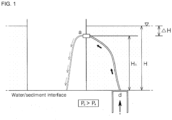
- FIG. 1 is a view conceptually showing the measurement of a saturated vertical hydraulic conductivity and a chamber is inserted into a stream bed deposit and an empty barrel is provided in the stream bed and a tube is installed between the chamber and the barrel.
- the height of the inlet of the empty barrel which is connected to the chamber by the tube, is located as low as ⁇ H lower than the water surface.
- the hydraulic head (Pd) inside the chamber 10 is ⁇ gH equal to the height of the water surface.
- the hydraulic head (Pa) of the connect point of the tube with the empty barrel is ⁇ gH1.
- the hydraulic head of the chamber is higher as long as ⁇ g ⁇ H than the hydraulic head of tube connect point at the inlet of the barrel.
- the groundwater of saturation zone is moving upwardly by the hydraulic head difference through the chamber so as to finally gather in the empty barrel.
- the hydraulic head difference is increased so that water flow passing through the chamber is increased.
- the vertical hydraulic conductivity of the sediment inside the chamber is calculated by the ratio of the hydraulic head difference between the two points inside the chamber and the water flow discharged to the empty barrel.
- FIG. 2 illustrating the meter for measuring the saturated vertical hydraulic conductivity by a chamber 10 and a measuring unit of vertical hydraulic conductivity 20
- the chamber 10 and a storage pipe 25 are installed with distanced apart from each other and their ends put into the bottom of stream, and rise perpendicularly out of water and sediment interface, and the chamber 10 and the storage pipe 25 are connected to each other by a connection line 40.
- the chamber 10 is embedded, the top end of the chamber 10 should be slowly pressed for the sediment not to be disturbed.
- the placing depth of the storage pipe 25 is determined so that an inlet 27 is placed lower than the water surface.
- the saturated vertical hydraulic conductivity (K) of the sand sediment by using the chamber 10 and the measuring unit of vertical hydraulic conductivity 20, can be measured by measuring the water exchange discharged according to the vertical hydraulic gradient artificially induced, and by analyzing the relation of the vertical hydraulic gradient and Darcian flux.
- the water exchange Darcian flux meter includes the chamber 10, the first and second hydraulic head measurement lines 21 and 22, the connection line 40, and the storage pipe 25.
- the chamber 10 is a cylindrical shape with empty there inside and its bottom open, and is perpendicularly embedded upright into the sediment at the surface water/sediment interface by slowly pressing the top end of the chamber 10.
- the chamber 10 is filled with the sediment of saturation zone, such as sand through the open bottom end.
- An extension line 11 is provided on the top end of the chamber 10 to be extended out of the water surface, and a level bar 12 is provided at the top end of the extension line 11 to be perpendicular to the extension line 11 so that it is determined whether the chamber 10 is perpendicularly embedded into the water surface/sediment interface through the level state of the level bar 12.
- the level bar 12 is also used as handle when installing or removing the chamber 10.
- a cover detachably placed at the top of the chamber 10 can be removed and then, the vertical hydraulic gradient can be measured with the top end and the bottom end of the chamber 10 are open. At this case, the extension line 11 and the level bar 12 of the extension line 11 can be also removed.
- the first and second hydraulic head measurement lines 21 and 22 are provided such that their respective one ends are connected at the upper and lower outer circumferences of the chamber 10 and the other ends are placed to protrude out of the surface water.
- the first hydraulic head measurement line 21 is connected to the upper circumference of the chamber 10 and the second hydraulic head measurement line 22 is connected to the lower circumference of the chamber 10 (relatively lower than the position of the first hydraulic head measurement line 21).
- the first and second hydraulic head measurement lines 21 and 22 are provided to measure the hydraulic head difference ( ⁇ h) due to the hydraulic head loss at the two different points in the chamber 10 as the water inside the chamber 10 is flowed from the lower portion to the upper portion of the chamber 10 (ex: manometer 23 and hand vacuum pump 24).
- the ends of the first and second hydraulic head measurement lines 21 and 22, which are connected to the chamber 10, are provided with mesh in order to prevent the sediment inside the chamber 10 induced into the lines 21 and 22.
- connection line 40 is made of a flexible tube, and its one end is connected to the top of the chamber 10 to be communicated with each other, and the other end of the connection line 40 is connected to the inlet 27 at the outer circumference of the storage pipe 25 to be communicated with each other.
- the water passing through the chamber 10 is induced into the inlet 27 of the storage pipe 25 through the connection line 40, (a nozzle is installed at the inlet 27 to be communicated with the connection line 40) so as to fill the storage pipe 25.
- the storage pipe 25 is a long and hollow tube, and has a circular shape in its cross section.
- the top end of the storage pipe 25 is open, and the other end thereof is pointed to form an insertion part 26 so that the storage pipe 25 can be firmly driven into the sediment.
- the storage pipe 25 is fixed to stand upright with a predetermined distance away from the chamber 10.
- the storage pipe 25 is fixed to the bottom of stream by pushing the sharp end of the insertion part 26 of the storage pipe 25 into the bottom of the stream.
- the open top end of the storage pipe 25 is directed upwardly to the opposite and the upper portion of the storage pipe 25 is out of the top surface of the stream upto a predetermined length so that the water of the stream is not inflowed into the storage pipe 25 through the top end of the storage pipe 25.
- the depth of the storage pipe 25 under the surface of the stream 25 is controlled by hitting a pressing part 28 which is protruded outwardly from the circumference of the storage pipe 25 by using a pressure means 29, a slide hammer.
- the storage pipe 25 is a cylindrical pipe of constant cross section, and it may be determined whether the amount of water and inflow rate of water are constant by detecting the change of the level of water induced into the storage pipe 25.
- the level of the water inside the storage pipe 25 is increased linearly. Therefore, Darcian flux can be calculated by selecting the linear block in which the water level is changed, and from the time period for the selected block, the total amount of inflow water, and the cross section area of the chamber 10.
- the level change of the water inside the storage pipe 25 can be measured by using a first automatic water level measurer 30 which is located at the bottom inside the storage pipe 25.
- Darcian flux and the hydraulic head difference ( ⁇ h) between the upper and lower portions inside the chamber 10 yields saturated vertical hydraulic conductivity of the sediment by the formula (1).
- the inlet 27 is placed on the outer circumference of the storage pipe 25, and the other end of the connection line 40 described above is connected to the inlet 27 to communicate with each other.
- the hydraulic head difference ( ⁇ H) between the storage pipe 25 and the chamber 10 can be controlled by varying the location of the inlet 27 of the storage pipe 25, that is, the location of the other end of the connection line 40 to communicate to the storage pipe 25.
- the inner diameter of the chamber 10 installed to stand straight on the sediment is 13.4cm
- the length of the chamber 10 is 40.0cm
- the clearance between the first and the second hydraulic head measuring lines 21, 22 connected to the chamber 10 is 20.0cm
- the first and the second hydraulic head measuring lines 21, 22 are respectively distanced with 10.0cm from the upper and lower portions of the chamber 10.
- the first and second hydraulic head measuring lines 21 and 22 and the storage pipe 25 are separated, and a vertical hydraulic gradient measuring unit 50 is connected in order to measure the vertical hydraulic gradient between the upper and lower portions, two points inside the chamber 10.
- the vertical hydraulic gradient measuring unit 50 includes first and second pipes 51 and 52, and second automatic level measurers 55a and 55b.
- connection line 40 When the storage pipe 25 is disconnected, the connection line 40 one end of which was connected to the storage pipe 25 is placed inside water, its one end being open inside water, the connection line 40 should be placed with distanced apart from the sediment with a predetermined length, so that the sediment is not to be induced into the chamber 10 through the connection line 40.
- the first and second pipes 51 and 52 are pipes having circular shape in cross section, its one bottom end being closed and its top end being open.
- the first and second pipes 51 and 52 are placed to stand right in face to each other with the chamber 10 placed between them.
- the first pipe 51 is placed in the left side of the outer circumference of the chamber 10, the upper portion of which is communicated with the first pipe 51.
- the second pipe 52 is placed in the right side of the outer circumference of the chamber 10, the lower portion of which is communicated with the second pipe 52.
- the lower portions of the first and second pipes 51 and 52 are gradually sharp-pointed so that the first and second pipes 51 and 52 and the chamber 10 are easily put into the sediment, and the upper portions of the first and second pipes 51 and 52 are exposed out of water with a predetermined length (the length of the first and second pipes 51 and 52 can be variously employed in advance by considering the changes of surface level of water).
- the automatic level measurers are installed inside the lowest of the first and second pipes 51 and 52 respectively at the same height so as to automatically and continuously measure the hydraulic head difference between the two portions of the chamber 10 (upper and lower portions respectively communicating with the first and second pipes 51 and 52).
- the water exchange through the chamber 10 can be achieved by multiplying the vertical hydraulic gradient value by the saturated vertical hydraulic conductivity value of the sediment inside the chamber 10.
- the experiment and measurement of the water exchange at the surface water/sediment interface by using the water exchange meter at surface water/sediment interface according to the present invention was performed at the Bangdu Bay (Hwang, 2002) located at the east of Jeju Island where the vertical flow of water at the surface water/sediment interface is clearly seen and the tide at the surface of the sea is highly fluctuating.
- the first and second pipes 51 and 52 are installed to stand right on both sides of the chamber 10, and distanced with a predetermined length apart from the chamber 10, which is inserted perpendicularly into the interface sediment (40cm in length and 13.4cm in diameter).
- the first and second pipes 51 and 52 are connected respectively to the chamber 10 to communicate with by two ports, at upper and lower portions of the chamber 10, and include the automatic level measurers 55a and 55b respectively at their lower sides there inside.
- a vertical hydraulic conductivity of the sand sediment filled inside the chamber 10 was measured by three times during the time when the tidal height changed from low to high before the hydraulic head difference inside the chamber 10 was measured.
- FIG. 9 shows an in-situ testing photograph where the water exchange was being measured by using the water exchange meter at the surface water/sediment interface according to the present invention.
- the first and second pipes 51 and 52 vertically standing as shown in the center of the photograph are a kind of a manometer for measuring the hydraulic head of two points of the chamber 10 which are distanced away from.
- the automatic level measurers 55a and 55b are respectively installed in the bottom of the first and second pipes 51 and 52 so as to measure the hydraulic head variance at each measurement location.
- the vertical hydraulic conductivity of the sand sediment inside the chamber 10 measured by three times are 0.032, 0.036, and 0.041 cm/sec, which are almost the same and thus indicate that the measurement values of the vertical hydraulic conductivity are highly correct because the correlation coefficient between the vertical hydraulic gradient and Darcian flux is 0.99 or higher.
- the vertical hydraulic conductivity obtained by using the measurement values of the vertical hydraulic gradient and Darcian flux is 0.034 cm/sec.
- the saturated vertical hydraulic conductivity in the calculation of the water exchange in the embodiment of the present invention is 0.034 cm/sec.
- FIGs. 11 and 12 show the head variance measured at upper and lower ports of the chamber 10.
- FIG. 13 shows the vertical hydraulic gradient variance calculated by subtracting the hydraulic head value at the upper port from the hydraulic head value at the lower port of the chamber 10, and dividing the hydraulic head difference between upper and lower ports of the chamber 10 by the vertical distance length (L) between the upper and lower ports.
- FIG. 14 shows Darcian flux (q) variance at measurement location obtained by multiplying the vertical hydraulic conductivity (K) at the measurement location by the vertical hydraulic gradient (i).
- FIG. 15 shows the water exchange variance at the surface water/sediment interface at the measurement location obtained by multiplying Darcian flux at the measurement location by the cross-section area of the chamber 10 and elapsed time.
- the hydraulic head measurement at two points of the chamber 10 uses the second automatic level measurers 55a and 55b which are commercialized, and the functions of the automatic level measurers 55a and 55b such as resolution of time measurements, measurement time period and so on can be maximized for use.
Landscapes
- Life Sciences & Earth Sciences (AREA)
- Chemical & Material Sciences (AREA)
- Engineering & Computer Science (AREA)
- Physics & Mathematics (AREA)
- General Physics & Mathematics (AREA)
- Geology (AREA)
- Mining & Mineral Resources (AREA)
- Analytical Chemistry (AREA)
- Health & Medical Sciences (AREA)
- Immunology (AREA)
- General Life Sciences & Earth Sciences (AREA)
- Biochemistry (AREA)
- General Health & Medical Sciences (AREA)
- Pathology (AREA)
- Fluid Mechanics (AREA)
- Dispersion Chemistry (AREA)
- Environmental & Geological Engineering (AREA)
- Geochemistry & Mineralogy (AREA)
- Food Science & Technology (AREA)
- Remote Sensing (AREA)
- Medicinal Chemistry (AREA)
- Soil Sciences (AREA)
- Paleontology (AREA)
- Civil Engineering (AREA)
- General Engineering & Computer Science (AREA)
- Structural Engineering (AREA)
- Investigating Or Analyzing Materials By The Use Of Electric Means (AREA)
- Investigation Of Foundation Soil And Reinforcement Of Foundation Soil By Compacting Or Drainage (AREA)
Description
- The present invention relates to a measuring device of water exchange at surface water/sediment interface by measuring a vertical hydraulic conductivity (K) and a vertical hydraulic gradient (i) in relation to the sediment beneath the surface water/sediment interface. More particularly, the present invention relates to a water exchange meter at surface water/sediment interface, which is given by laying a cylindrical chamber, open at its bottom but closed at its top, into the sediment beneath the surface water/sediment interface, and being capable of automatically and continuously measuring the water exchange at the surface water/sediment interface by measuring a saturated vertical hydraulic conductivity of the sediment inside the chamber, and while maintaining the chamber, by measuring a vertical hydraulic gradient between two different level elevations of the chamber.
- Surface water and ground-water interaction is very active and mutually communicated with each other, while physical and chemical changes in either one influence to the other one. Thus, surface water and groundwater have been recognized as one interplaying resource. Surface water and groundwater interaction is the subject essentially required to research and verify in many aspects such as analysis of hydrological balance, finding of transfer paths of nutrients and contaminants, research and development of groundwater movement systems, securing and planning of water resources, and so on. Surface water and groundwater interaction includes the discharge of water from aquifer (water bearing layer) to surface water layer or recharge of water from surface water layer to water bearing layer. It is desperately required to develop the methods and the means of directly or indirectly measuring the water exchange amount at the surface water/sediment interface in order to quantitatively analyze the discharge and the recharge of water at the surface water/sediment interface.
- Until now, various methods have been proposed and employed in order to directly or indirectly measure the mutual interaction and water exchange amount of surface water and groundwater, for example, the method based on modeling, natural tracer, seepage meter, and temperature profiling, or (as known e.g. from
EP 2 725 340 A2 ) the method of calculating the water exchange by measuring a vertical hydraulic gradient and a vertical hydraulic conductivity (Burnett et al., 2006). Among them, the seepage meter which is normally applied for water exchange measuring means in the search field except for natural tracer, and Darcian flux calculation of measuring water exchange amount by using a vertical hydraulic gradient and a vertical hydraulic conductivity (Mulligan and Charette, 2006) are mostly used. The seepage meter was used in 1940s and 1950s in order to measure water loss amount in irrigation ditches (Israelson and Reeve, 1944), and Lee (1977) designed a half-barrel seepage meter and used for the interaction research and evaluation of groundwater and stream water. As the efforts to solve and overcome the problems and disadvantages raised in the seepage meter by Lee (1977), there have been proposed seepage meters enabled to continuously and automatically measure the water exchange by using various methods, such as Heat pulse (Taniguchi and Fukuo, 1993), Continuous heat pulse (Taniguchi and Iwakawa, 2001), Ultrasonic (Paulsen et al.,2001), Dye-dilution (Sholkovitz et al., 2003), and so on. However, the automatic seepage meters as above are not commercialized yet, and thus, many researchers still use the seepage meter by the method of Lee (1977) for now, but the problem due to low reliability in the measured values by the Lee type seepage meter is still remained (Belanger and Montgomery, 1992). - The Darcian flux calculation as above is the method of calculating Oarcian flux (q) from a vertical hydraulic conductivity of the sediment at the surface water interface and a vertical hydraulic gradient. The correctness and preciseness of the measurement results by the Darcian flux depends on the reliability of the values of the vertical hydraulic conductivity and the vertical hydraulic gradient. However, errors occurred when the measurement locations of the vertical hydraulic conductivity and the vertical hydraulic gradient are varied are still raised as problems to be solved.
- Therefore, research and development of the means for measuring water exchange at the surface water/sediment interface by the Darcian flux calculation method in order to solve the above problems has been desperately required.
- Therefore, the present invention has been made to solve the above problems. The invention is set out in the appended set of claims.
- In accordance with the present invention, the above and other aspects can be accomplished by measuring the vertical hydraulic conductivity of the sediment filled inside the
chamber 10 by using the permeameter for in-situ measurements of saturated hydraulic conductivity (registration No. 10-1366057) by the inventor of the present invention and then, by disconnecting aconnection line 40 connecting astorage pipe 25 and thechamber 10 so that one end of theconnection line 40 to thechamber 10 is open and placed inside water to freely come in and out, or by opening the top and bottom end of thechamber 10 so that the water through the sediment filling thechamber 10 is freely flowed in the vertical direction, and then by installing a vertical hydraulicgradient measuring unit 50 detachably and respectively at both sides to thechamber 10 and to communicate with thechamber 10 via the upper and lower portions of thechamber 10, so as to continuously measure a vertical hydraulic gradient between upper and lower portions of thechamber 10 distanced apart from each other. - The Darcy's law which is used in the present invention is a phenomenologically derived equation which describes the flow of a fluid through a porous medium such as sand layer, and is formulated based on the results that the water in the porous medium flows from higher hydraulic head to lower hydraulic head, and the flow of the water through the porous medium is proportional to a vertical hydraulic conductivity and a vertical hydraulic gradient (Equation 1). The
Equation 1 describes Darcian flux (q), which is the discharge per area and per time of fluid at the surface water/sediment interface, derived by achieving the vertical hydraulic gradient (i) based on experiments, and then, multiplying a vertical hydraulic conductivity (K) to the vertical hydraulic gradient (i). Therefore, the water exchange at the surface water/sediment interface is calculated by multiplying the cross-section area (A) of achamber 10 and the measured times (t) to the Darcian flux (q).
- As described above, in accordance with the present invention, the water exchange at the surface water/sediment interface can be automatically and continuously measured by which a saturated vertical hydraulic conductivity of the sediment where the measurement takes place is measured and then, while the meter of the present invention is maintained, a vertical hydraulic gradient between two different level upper and lower elevations inside the chamber is continuously measured.
- These and other aspects and advantages of the present invention will become apparent and more readily appreciated from the following description of the embodiments, taken in conjunction with the accompanying drawings, in which:
-
FIG. 1 is a schematic view conceptually showing the measurement of a saturated vertical hydraulic conductivity by using the hydraulic head difference between astorage pipe 25 and achamber 10; -
FIG. 2 is a schematic view conceptually showing the configuration of the meter for measuring a vertical hydraulic conductivity (permeameter for in-situ measurements of saturated hydraulic conductivity; registration No. 10-1366057); -
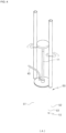
FIG. 3 is a schematic view conceptually showing the configuration of the meter for measuring a vertical hydraulic gradient inside a chamber according to the present invention; -
FIG. 4 is a perspective view ofFIG. 3 ; -
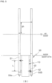
FIG. 5 is a schematic view showing the configuration of the meter for measuring a vertical hydraulic gradient with the top of thechamber 10 being open; -
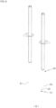
FIG. 6 is a perspective view ofFIG. 5 ; -
FIG. 7 is a view of showing in-situ testing location; -
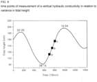
FIG. 8 is a view showing the time points of measurement of a vertical hydraulic conductivity in relation to variance in tidal height; -
FIG. 9 is an in-situ testing photograph showing the meter; -
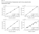
FIG. 10 is a view of the graphs showing the values of the vertical hydraulic conductivity (a, b, c) at time points of measurement, and the vertical hydraulic conductivity (d) by using the entire measurement values; -
FIG. 11 is a graph showing head variance measured at upper port of the chamber; -
FIG. 12 is a graph showing head variance measured at lower port of the chamber; -
FIG. 13 is a graph showing vertical hydraulic gradient variance between upper and lower ports of the chamber by using difference in head between vertically distal two points of the chamber and the distance between upper and lower ports of the chamber; -
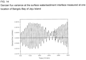
FIG. 14 is a graph showing Darcian flux variance at measurement location obtained by applying the vertical hydraulic conductivity (0.034 cm/sec) at the measurement location and the vertical hydraulic gradient to Darcy's law (Equation (1)); and -
FIG. 15 is a graph showing the water exchange variance per time (10 minutes) at the measurement location obtained by multiplying Darcian flux at the measurement location and the cross-section area of thechamber 10 by elapsed time. -
10: chamber 11: connection line 12: level bar 20: measuring unit of vertical hydraulic conductivity 21: first hydraulic head measurement line 22: second hydraulic head measurement line 23: manometer 24: hand vacuum pump 25: storage pipe 26: insertion part 27: inlet 28: pressing part 29: pressure means 30: first automatic water level measurer 40: connection line 50: vertical hydraulic gradient measuring unit 51: first pipe 52: second pipe 53: communicater 54a, 55b: second automatic level measurers - The present invention will now be described more fully hereinafter with reference to the accompanying drawings.
-
FIG. 1 is a view conceptually showing the measurement of a saturated vertical hydraulic conductivity and a chamber is inserted into a stream bed deposit and an empty barrel is provided in the stream bed and a tube is installed between the chamber and the barrel. The height of the inlet of the empty barrel which is connected to the chamber by the tube, is located as low as ΔH lower than the water surface. When ignoring the interaction of surface water and sediment such as gain stream or loss stream, the hydraulic head (Pd) inside thechamber 10 is ρ gH equal to the height of the water surface. The hydraulic head (Pa) of the connect point of the tube with the empty barrel is ρ gH1. The hydraulic head of the chamber is higher as long as ρ g△H than the hydraulic head of tube connect point at the inlet of the barrel. The groundwater of saturation zone is moving upwardly by the hydraulic head difference through the chamber so as to finally gather in the empty barrel. As △H is increased, the hydraulic head difference is increased so that water flow passing through the chamber is increased. At this time, the vertical hydraulic conductivity of the sediment inside the chamber is calculated by the ratio of the hydraulic head difference between the two points inside the chamber and the water flow discharged to the empty barrel. - As shown in
FIG. 2 illustrating the meter for measuring the saturated vertical hydraulic conductivity by achamber 10 and a measuring unit of verticalhydraulic conductivity 20, thechamber 10 and astorage pipe 25 are installed with distanced apart from each other and their ends put into the bottom of stream, and rise perpendicularly out of water and sediment interface, and thechamber 10 and thestorage pipe 25 are connected to each other by aconnection line 40. As thechamber 10 is embedded, the top end of thechamber 10 should be slowly pressed for the sediment not to be disturbed. The placing depth of thestorage pipe 25 is determined so that aninlet 27 is placed lower than the water surface. As thestorage pipe 25 is embedded into the sediment to rise perpendicularly so that theinlet 27 of thestorage pipe 25 is placed lower than the water surface, the hydraulic head difference between theinlet 27 and thechamber 10 is generated, and due to this hydraulic head difference (△H), water is flowed from thechamber 10 to theinlet 27 of thestorage pipe 25. The groundwater around thechamber 10 is induced into thechamber 10 so as to cause the water flow from the lower portion to the upper portion of thechamber 10 and incur the hydraulic head difference (△h) between the lower portion and the upper portion of thechamber 10. As the placing depth of theinlet 27 of thestorage pipe 25 under the water surface is fixed, the water flow passing through thechamber 10 and the hydraulic head difference (△h) between the lower and the upper portion of thechamber 10 are constant. Thus, the ratio of these values of the measurement is calculated which is vertical hydraulic conductivity (the vertical hydraulic conductivity in Darcy's law is ratio of Darcian flux to hydraulic gradient.) - Hereinafter, referring to
FIGs. 2 to 15 , the measurement of the saturated vertical hydraulic conductivity by using the meter of measuring water exchange at the surface water/sediment interface according to one embodiment of the present invention will be described in detail. - As illustrated in
FIG. 2 showing the water exchange Darcian flux meter at the surface water/sediment interface according to one embodiment of the present invention, the saturated vertical hydraulic conductivity (K) of the sand sediment by using thechamber 10 and the measuring unit of verticalhydraulic conductivity 20, can be measured by measuring the water exchange discharged according to the vertical hydraulic gradient artificially induced, and by analyzing the relation of the vertical hydraulic gradient and Darcian flux. The water exchange Darcian flux meter includes thechamber 10, the first and second hydraulichead measurement lines connection line 40, and thestorage pipe 25. - The
chamber 10 is a cylindrical shape with empty there inside and its bottom open, and is perpendicularly embedded upright into the sediment at the surface water/sediment interface by slowly pressing the top end of thechamber 10. Thechamber 10 is filled with the sediment of saturation zone, such as sand through the open bottom end. Anextension line 11 is provided on the top end of thechamber 10 to be extended out of the water surface, and alevel bar 12 is provided at the top end of theextension line 11 to be perpendicular to theextension line 11 so that it is determined whether thechamber 10 is perpendicularly embedded into the water surface/sediment interface through the level state of thelevel bar 12. Thelevel bar 12 is also used as handle when installing or removing thechamber 10. A cover detachably placed at the top of thechamber 10 can be removed and then, the vertical hydraulic gradient can be measured with the top end and the bottom end of thechamber 10 are open. At this case, theextension line 11 and thelevel bar 12 of theextension line 11 can be also removed. - The first and second hydraulic
head measurement lines chamber 10 and the other ends are placed to protrude out of the surface water. The first hydraulichead measurement line 21 is connected to the upper circumference of thechamber 10 and the second hydraulichead measurement line 22 is connected to the lower circumference of the chamber 10 (relatively lower than the position of the first hydraulic head measurement line 21). The first and second hydraulichead measurement lines chamber 10 as the water inside thechamber 10 is flowed from the lower portion to the upper portion of the chamber 10 (ex:manometer 23 and hand vacuum pump 24). The ends of the first and second hydraulichead measurement lines chamber 10, are provided with mesh in order to prevent the sediment inside thechamber 10 induced into thelines - The
connection line 40 is made of a flexible tube, and its one end is connected to the top of thechamber 10 to be communicated with each other, and the other end of theconnection line 40 is connected to theinlet 27 at the outer circumference of thestorage pipe 25 to be communicated with each other. Thus, the water passing through thechamber 10 is induced into theinlet 27 of thestorage pipe 25 through theconnection line 40, (a nozzle is installed at theinlet 27 to be communicated with the connection line 40) so as to fill thestorage pipe 25. - The
storage pipe 25 is a long and hollow tube, and has a circular shape in its cross section. The top end of thestorage pipe 25 is open, and the other end thereof is pointed to form aninsertion part 26 so that thestorage pipe 25 can be firmly driven into the sediment. Thestorage pipe 25 is fixed to stand upright with a predetermined distance away from thechamber 10. Thestorage pipe 25 is fixed to the bottom of stream by pushing the sharp end of theinsertion part 26 of thestorage pipe 25 into the bottom of the stream. The open top end of thestorage pipe 25 is directed upwardly to the opposite and the upper portion of thestorage pipe 25 is out of the top surface of the stream upto a predetermined length so that the water of the stream is not inflowed into thestorage pipe 25 through the top end of thestorage pipe 25. The depth of thestorage pipe 25 under the surface of thestream 25 is controlled by hitting apressing part 28 which is protruded outwardly from the circumference of thestorage pipe 25 by using a pressure means 29, a slide hammer. - The
storage pipe 25 is a cylindrical pipe of constant cross section, and it may be determined whether the amount of water and inflow rate of water are constant by detecting the change of the level of water induced into thestorage pipe 25. When the inflow rate of water induced into thestorage pipe 25 is constant, the level of the water inside thestorage pipe 25 is increased linearly. Therefore, Darcian flux can be calculated by selecting the linear block in which the water level is changed, and from the time period for the selected block, the total amount of inflow water, and the cross section area of thechamber 10. The level change of the water inside thestorage pipe 25 can be measured by using a first automaticwater level measurer 30 which is located at the bottom inside thestorage pipe 25. Darcian flux and the hydraulic head difference (△h) between the upper and lower portions inside thechamber 10 yields saturated vertical hydraulic conductivity of the sediment by the formula (1). - The
inlet 27 is placed on the outer circumference of thestorage pipe 25, and the other end of theconnection line 40 described above is connected to theinlet 27 to communicate with each other. The hydraulic head difference (△H) between thestorage pipe 25 and thechamber 10 can be controlled by varying the location of theinlet 27 of thestorage pipe 25, that is, the location of the other end of theconnection line 40 to communicate to thestorage pipe 25. The lower theinlet 27 to which theconnection line 40 is connected to becomes inside water stream (theinlet 27 is directed to the other end of the storage pipe 25), the hydraulic head difference (△H) between thestorage pipe 25 and thechamber 10 is increased, and so, the amount of water Q which is induced into thestorage pipe 25 is also increased. With variance of the location of theinlet 27 of thestorage pipe 25 by intervals, Darcian flux in each interval which is induced and stored from thechamber 10 into thestorage pipe 25, and the hydraulic head difference (6h) between the upper and lower portions of thechamber 10 are measured, so as to calculate saturated vertical hydraulic conductivity of the sediments to be concerned in each interval. As the vertical hydraulic conductivity of the porous medium inside thechamber 10 to be measured is unique constant in each medium, and if the vertical hydraulic conductivity in each interval is correctly measured, the values of vertical hydraulic conductivity in all intervals must be same so that the vertical hydraulic gradient in each interval and Darcian flux must show a linear function relation. That is, it is possible to verify the accuracy of the vertical hydraulic conductivity obtained by the meter of the present invention by either way of simply comparing the vertical hydraulic conductivity in each interval, or seeing whether vertical hydraulic gradient in each interval and Darcian flux must show a linear function relation, or by determining whether the straight line leaning of the linear function of the relation is equal to the vertical hydraulic conductivity pre-known or not. - The inner diameter of the
chamber 10 installed to stand straight on the sediment is 13.4cm, the length of thechamber 10 is 40.0cm, and the clearance between the first and the second hydraulichead measuring lines chamber 10 is 20.0cm, and the first and the second hydraulichead measuring lines chamber 10. - After measuring the saturated vertical hydraulic conductivity as described above, now it will be described below one embodiment of the present invention in order to measure the water exchange at the surface water/sediment interface by continuously measuring the hydraulic head difference between the two portions of the chamber 10 (upper and lower portions) in the water exchange meter at the surface water/sediment interface according to the present invention.
- As shown in
FIGs. 3 to 6 , in the structure of the measuring unit of verticalhydraulic conductivity 20 which was used to measure the saturated vertical hydraulic conductivity as described, the first and second hydraulichead measuring lines storage pipe 25 are separated, and a vertical hydraulicgradient measuring unit 50 is connected in order to measure the vertical hydraulic gradient between the upper and lower portions, two points inside thechamber 10. The vertical hydraulicgradient measuring unit 50 includes first andsecond pipes automatic level measurers 55a and 55b. - When the
storage pipe 25 is disconnected, theconnection line 40 one end of which was connected to thestorage pipe 25 is placed inside water, its one end being open inside water, theconnection line 40 should be placed with distanced apart from the sediment with a predetermined length, so that the sediment is not to be induced into thechamber 10 through theconnection line 40. - The first and
second pipes second pipes chamber 10 placed between them. Thefirst pipe 51 is placed in the left side of the outer circumference of thechamber 10, the upper portion of which is communicated with thefirst pipe 51. Thesecond pipe 52 is placed in the right side of the outer circumference of thechamber 10, the lower portion of which is communicated with thesecond pipe 52. - The lower portions of the first and
second pipes second pipes chamber 10 are easily put into the sediment, and the upper portions of the first andsecond pipes second pipes - The automatic level measurers are installed inside the lowest of the first and
second pipes second pipes 51 and 52). - By hydraulic head difference (Ah) obtained from the two hydraulic heads of the
chamber 10 which are communicated with the first andsecond pipes - Thus, the water exchange through the
chamber 10 can be achieved by multiplying the vertical hydraulic gradient value by the saturated vertical hydraulic conductivity value of the sediment inside thechamber 10. - The experiment and measurement of the water exchange at the surface water/sediment interface by using the water exchange meter at surface water/sediment interface according to the present invention was performed at the Bangdu Bay (Hwang, 2002) located at the east of Jeju Island where the vertical flow of water at the surface water/sediment interface is clearly seen and the tide at the surface of the sea is highly fluctuating.
- The first and
second pipes chamber 10, and distanced with a predetermined length apart from thechamber 10, which is inserted perpendicularly into the interface sediment (40cm in length and 13.4cm in diameter). The first andsecond pipes chamber 10 to communicate with by two ports, at upper and lower portions of thechamber 10, and include theautomatic level measurers 55a and 55b respectively at their lower sides there inside. - As illustrated in
FIG. 8 , a vertical hydraulic conductivity of the sand sediment filled inside thechamber 10 was measured by three times during the time when the tidal height changed from low to high before the hydraulic head difference inside thechamber 10 was measured. -
FIG. 9 shows an in-situ testing photograph where the water exchange was being measured by using the water exchange meter at the surface water/sediment interface according to the present invention. The first andsecond pipes chamber 10 which are distanced away from. Theautomatic level measurers 55a and 55b are respectively installed in the bottom of the first andsecond pipes - As shown in
FIG. 10 , the vertical hydraulic conductivity of the sand sediment inside thechamber 10 measured by three times are 0.032, 0.036, and 0.041 cm/sec, which are almost the same and thus indicate that the measurement values of the vertical hydraulic conductivity are highly correct because the correlation coefficient between the vertical hydraulic gradient and Darcian flux is 0.99 or higher. The vertical hydraulic conductivity obtained by using the measurement values of the vertical hydraulic gradient and Darcian flux is 0.034 cm/sec. The saturated vertical hydraulic conductivity in the calculation of the water exchange in the embodiment of the present invention is 0.034 cm/sec. -
FIGs. 11 and 12 show the head variance measured at upper and lower ports of thechamber 10.FIG. 13 shows the vertical hydraulic gradient variance calculated by subtracting the hydraulic head value at the upper port from the hydraulic head value at the lower port of thechamber 10, and dividing the hydraulic head difference between upper and lower ports of thechamber 10 by the vertical distance length (L) between the upper and lower ports.FIG. 14 shows Darcian flux (q) variance at measurement location obtained by multiplying the vertical hydraulic conductivity (K) at the measurement location by the vertical hydraulic gradient (i).FIG. 15 shows the water exchange variance at the surface water/sediment interface at the measurement location obtained by multiplying Darcian flux at the measurement location by the cross-section area of thechamber 10 and elapsed time. - The disadvantages, such as errors of values, caused by the existing measurement devices in which the locations where measurement tests are performed to measure the vertical hydraulic conductivity and the vertical hydraulic gradient are different can be removed to the utmost according to the water exchange meter of the present invention because the vertical hydraulic conductivity and the vertical hydraulic gradient are measured at the same place.
- The hydraulic head measurement at two points of the
chamber 10 uses the secondautomatic level measurers 55a and 55b which are commercialized, and the functions of theautomatic level measurers 55a and 55b such as resolution of time measurements, measurement time period and so on can be maximized for use. -
- Belanger and Montgomery, 1992, Seepage meter errors. Limnol. Oceanogr.. 37(8), 1787-1795.
- Burnett W.C., Aggarwal P.K., Aureli H., Bokuniewicz, Cable J.E., M.A. Charette f, E. Kontar g, S. Krupa h, K.M. Kulkarni b, A. Loveless i, W.S. Moore j, J.A. Oberdorfer k, J. Oliveira I, N. Ozyurt m, P. Povinec n,1, A.M.G. Privitera o, R. Rajar p, R.T. Ramessur q, J. Scholten n, T. Stieglitz r,s, M. Taniguchi t, J.V. Turner, 2006, Quantifying submarine groundwater discharge in the coastal zone via multiple methods. Science of the total environment. doi:10.1016/j.scitotenv.2006.05.009
- Israelsen O.W,, Reeve R.C.. 1944, Canal lining experiments in the delta area, Utah. Utah Agr Exp Sta Tech Bull 313 52pp
- Lee D.R., 1977, A device for measuring seepage flux in lakes and estuaries. .
- Mulligan, A. E. and Charette, M. A., 2006, Intercomparison of submarine groundwater discharge estimates from a sandy unconfined aquifer. Journal of hydrology, 327, 411-425.
- Paulsen RJ, Smith CF, O'Rourke D, Wong T., 2001, Development and evaluation of an ultrasonic ground water seepage meter. Ground Water 39:904-.11.
- Sholkovitz E.R., Herbold C. and Charette M.A.., 2003, An automated dye-dilution based seepage meter for the time-series measurement of submarine groundwater discharge. Limnol Oceanogr Methods 1:17-.29.
- Taniguchi M and Fukuo Y., 1993, Continuous measurements of ground-water seepage using an automatic seepage meter. Ground Water 31:675-.9.
- Taniguchi M and Iwakawa H., 2001, Measurements of submarine groundwater discharge rates by a continuous heat-type automated seepage meter in Osaka Bay, Japan. J Groundw Hydrol 43:271-.7.
Claims (2)
- A water exchange meter for measuring the water exchange at surface water/sediment interface comprisinga chamber (10) with an open bottom end and configured to be inserted into streambed sediment at the bottom of a stream such that the inside of the chamber (10) is filled with the sediment medium; a connection line (40);a measuring unit of vertical hydraulic conductivity (20) to be removably connected with the chamber (10), wherein the measuring unit of vertical hydraulic conductivity (20) includes a storage pipe (25) with an inlet (27) to communicate with the chamber (10) by the connection line (40) and wherein, in use, when the inlet (27) is placed lower than the water surface, there is a hydraulic head difference generated between the inlet (27) and the chamber (10) and wherein the measuring unit of hydraulic conductivity is configured to measure the amount of the water induced to flow into the storage pipe (25) from the chamber (10) and to measure the flow rate of the water so as to obtain a saturated vertical hydraulic conductivity of the sediment medium, and wherein the water exchange meter further includes a manometer (23) and first and second hydraulic head measuring lines (21,22) for measuring a hydraulic head difference within the chamber and wherein the first and second hydraulic head measuring lines (21, 22) are connected to the manometer (23) at their respective one ends, wherein their other ends are to be removably connected at the upper and lower outer circumference of the chamber, respectively,characterized in that the water exchange meter further comprisesa vertical hydraulic gradient measuring unit (50) that is to be connected to the chamber after the saturated vertical hydraulic conductivity is measured and the measuring unit of vertical hydraulic conductivity is removed from the chamber, wherein the vertical hydraulic gradient measuring unit (50) is communicatedly connected to the chamber (10) through upper and lower portions of the chamber (10) for continuously measuring the vertical hydraulic gradient between the upper and lower portions of the chamber (10) after removing first and second hydraulic head measuring lines (21,22) and after removing the storage pipe (25); whereinthe vertical hydraulic gradient measuring unit (50) is to be detachably connected with the chamber (10), and comprises:first and second pipes (51, 52) for installing upright on the bottom of the stream with the chamber (10) placed between them, one of the pipes (51, 52) being connected communicatingly with the upper portion of the chamber (10), and the other pipe (51, 52) being connected communicatingly with the lower portion of the chamber (10), wherein both pipes (51, 52) have open top ends, andautomatic level measurers (55a, 55b) that are respectively installed inside the bottom of the first and second pipes (51, 52) so as to continuously measure said vertical hydraulic gradient, wherein, in use, by multiplying the vertical hydraulic gradient and the saturated vertical hydraulic conductivity, the water exchange through the chamber can be derived.
- Use of the water exchange meter according to claim 1, wherein, after removing the measuring unit of vertical hydraulic conductivity (20) from the chamber (10), the vertical hydraulic gradient measuring unit (50) is connected to said chamber (10) to measure vertical hydraulic conductivity and hydraulic gradient at the same place.
Applications Claiming Priority (1)
| Application Number | Priority Date | Filing Date | Title |
|---|---|---|---|
| KR1020140055104A KR101541342B1 (en) | 2014-05-08 | 2014-05-08 | Darcian flux meter |
Publications (2)
| Publication Number | Publication Date |
|---|---|
| EP2942613A1 EP2942613A1 (en) | 2015-11-11 |
| EP2942613B1 true EP2942613B1 (en) | 2023-07-05 |
Family
ID=53180534
Family Applications (1)
| Application Number | Title | Priority Date | Filing Date |
|---|---|---|---|
| EP15166209.5A Active EP2942613B1 (en) | 2014-05-08 | 2015-05-04 | Darcian flux meter of water exchange at surface water/sediment interface |
Country Status (3)
| Country | Link |
|---|---|
| US (1) | US9658093B2 (en) |
| EP (1) | EP2942613B1 (en) |
| KR (1) | KR101541342B1 (en) |
Families Citing this family (6)
| Publication number | Priority date | Publication date | Assignee | Title |
|---|---|---|---|---|
| US10208585B2 (en) | 2015-08-11 | 2019-02-19 | Intrasen, LLC | Groundwater monitoring system and method |
| CN109682950B (en) * | 2019-02-11 | 2021-06-08 | 河海大学 | Method for determining hydraulic slope value of fault zone nonlinear flow infiltration damage |
| CN110749415B (en) * | 2019-09-25 | 2021-08-31 | 河海大学 | A lateral undercurrent exchange experimental device for simulating river bank undulation conditions and using method |
| CN111323548B (en) * | 2020-04-14 | 2022-09-16 | 吕笑非 | Incubator for sea-land staggered zone ecological system, control method and application |
| KR102225911B1 (en) * | 2021-01-25 | 2021-03-11 | 한국지질자원연구원 | Falling head test method and apparatus for measuring saturated hydraulic conductivity of soils |
| CN113358426B (en) * | 2021-06-11 | 2022-05-06 | 重庆师范大学 | Acquisition device and method for measuring emission contribution of endogenous greenhouse gases in shallow water body |
Family Cites Families (5)
| Publication number | Priority date | Publication date | Assignee | Title |
|---|---|---|---|---|
| GB990591A (en) * | 1962-11-13 | 1965-04-28 | Nat Res Dev | Apparatus for investigating seepage of liquids through the beds of reservoirs and the like |
| US6571605B2 (en) * | 2001-01-19 | 2003-06-03 | Larry Keith Johnson | Constant-head soil permeameter for determining the hydraulic conductivity of earthen materials |
| US8825430B2 (en) * | 2008-11-03 | 2014-09-02 | Ann E. Mulligan | Differential pressure systems and methods for measuring hydraulic parameters across surface water-aquifer interfaces |
| KR101252136B1 (en) * | 2011-07-12 | 2013-04-08 | 한국지질자원연구원 | automated seepage meter for groundwater discharge and recharge |
| KR101366057B1 (en) * | 2012-10-26 | 2014-02-26 | 한국지질자원연구원 | Permeameter for in-situ measurements of saturated hydraulic conductivity |
-
2014
- 2014-05-08 KR KR1020140055104A patent/KR101541342B1/en active Active
-
2015
- 2015-04-30 US US14/700,727 patent/US9658093B2/en not_active Expired - Fee Related
- 2015-05-04 EP EP15166209.5A patent/EP2942613B1/en active Active
Also Published As
| Publication number | Publication date |
|---|---|
| KR101541342B1 (en) | 2015-08-04 |
| US9658093B2 (en) | 2017-05-23 |
| US20150323363A1 (en) | 2015-11-12 |
| EP2942613A1 (en) | 2015-11-11 |
Similar Documents
| Publication | Publication Date | Title |
|---|---|---|
| EP2942613A1 (en) | Darcian flux meter of water exchange at surface water/sediment interface | |
| KR101366057B1 (en) | Permeameter for in-situ measurements of saturated hydraulic conductivity | |
| Kluge et al. | Tracing and quantifying groundwater inflow into lakes using a simple method for radon-222 analysis | |
| CN102483342B (en) | A method and soil moisture sensor for determining ground elevation | |
| Boersma | Field measurement of hydraulic conductivity below a water table | |
| RU2533318C2 (en) | Flow meter system, and measuring method of amount of liquid in multiphase flow with large content of gaseous phase | |
| CN106645639B (en) | Observation device and method for quantitatively measuring moisture supply amount from sand dune to inter-dune land | |
| CN101738356B (en) | Method for measuring and calculating soil wetting front suction | |
| KR101652370B1 (en) | Flux meter for measuring exchanges of water and mass across groundwater-surface water interface | |
| CN106018239A (en) | Method and device for measuring permeability coefficients of stratums at different depths in field | |
| KR102225911B1 (en) | Falling head test method and apparatus for measuring saturated hydraulic conductivity of soils | |
| US7141982B2 (en) | Estimation of leakage rates using voltage measurements | |
| CN112033848B (en) | Detection management method and device for lysimeter and detection management equipment | |
| US6810755B1 (en) | Permeameter system and method to determine soil hydraulic capacity for onsite wastewater systems | |
| CN117055127A (en) | A method for detecting groundwater connection channel types | |
| CN105095669B (en) | The evaluation method of slope ground surface roughness and infiltration parameter under the conditions of current scour | |
| WO2008081468A1 (en) | Tritium injection technique for the estimation of natural groundwater recharge | |
| CN106198347A (en) | Rock seepage rate Auto-Test System and method of testing | |
| KR101603077B1 (en) | Modified method of advective velocity and effective porosity in convergent radial flow tracer test | |
| CN109932300B (en) | A self-starting negative pressure drainage test device | |
| CN207351836U (en) | For salt-soda soil and there is the Weighing Lysimeter that the desalinization of soil by flooding or leaching is circulated in moisture | |
| HU206758B (en) | Method for determining the probable dimensions of groundwater sources | |
| CA2424112A1 (en) | A method and apparatus for combined nmr and formation testing for assessing relative permeability with formation testing and nuclear magnetic resonance testing | |
| RU2018157C1 (en) | Method of determination of parameters of underground space | |
| CN114878096A (en) | Test device and method for determining river leakage |
Legal Events
| Date | Code | Title | Description |
|---|---|---|---|
| PUAI | Public reference made under article 153(3) epc to a published international application that has entered the european phase |
Free format text: ORIGINAL CODE: 0009012 |
|
| 17P | Request for examination filed |
Effective date: 20150518 |
|
| AK | Designated contracting states |
Kind code of ref document: A1 Designated state(s): AL AT BE BG CH CY CZ DE DK EE ES FI FR GB GR HR HU IE IS IT LI LT LU LV MC MK MT NL NO PL PT RO RS SE SI SK SM TR |
|
| AX | Request for extension of the european patent |
Extension state: BA ME |
|
| RBV | Designated contracting states (corrected) |
Designated state(s): AL AT BE BG CH CY CZ DE DK EE ES FI FR GB GR HR HU IE IS IT LI LT LU LV MC MK MT NL NO PL PT RO RS SE SI SK SM TR |
|
| STAA | Information on the status of an ep patent application or granted ep patent |
Free format text: STATUS: EXAMINATION IS IN PROGRESS |
|
| 17Q | First examination report despatched |
Effective date: 20200423 |
|
| REG | Reference to a national code |
Ref country code: DE Ref legal event code: R079 Ref document number: 602015084411 Country of ref document: DE Free format text: PREVIOUS MAIN CLASS: G01N0015080000 Ipc: E21B0049000000 Ref country code: DE Ref legal event code: R079 Free format text: PREVIOUS MAIN CLASS: G01N0015080000 Ipc: E21B0049000000 |
|
| RIC1 | Information provided on ipc code assigned before grant |
Ipc: G01N 15/08 20060101ALI20221214BHEP Ipc: E21B 49/00 20060101AFI20221214BHEP |
|
| GRAP | Despatch of communication of intention to grant a patent |
Free format text: ORIGINAL CODE: EPIDOSNIGR1 |
|
| STAA | Information on the status of an ep patent application or granted ep patent |
Free format text: STATUS: GRANT OF PATENT IS INTENDED |
|
| INTG | Intention to grant announced |
Effective date: 20230120 |
|
| RAP3 | Party data changed (applicant data changed or rights of an application transferred) |
Owner name: KOREA INSTITUTE OF GEOSCIENCE AND MINERAL RESOURCES |
|
| GRAS | Grant fee paid |
Free format text: ORIGINAL CODE: EPIDOSNIGR3 |
|
| GRAA | (expected) grant |
Free format text: ORIGINAL CODE: 0009210 |
|
| STAA | Information on the status of an ep patent application or granted ep patent |
Free format text: STATUS: THE PATENT HAS BEEN GRANTED |
|
| AK | Designated contracting states |
Kind code of ref document: B1 Designated state(s): AL AT BE BG CH CY CZ DE DK EE ES FI FR GB GR HR HU IE IS IT LI LT LU LV MC MK MT NL NO PL PT RO RS SE SI SK SM TR |
|
| REG | Reference to a national code |
Ref country code: CH Ref legal event code: EP |
|
| REG | Reference to a national code |
Ref country code: AT Ref legal event code: REF Ref document number: 1585030 Country of ref document: AT Kind code of ref document: T Effective date: 20230715 |
|
| REG | Reference to a national code |
Ref country code: DE Ref legal event code: R096 Ref document number: 602015084411 Country of ref document: DE |
|
| REG | Reference to a national code |
Ref country code: IE Ref legal event code: FG4D |
|
| REG | Reference to a national code |
Ref country code: LT Ref legal event code: MG9D |
|
| REG | Reference to a national code |
Ref country code: NL Ref legal event code: MP Effective date: 20230705 |
|
| REG | Reference to a national code |
Ref country code: AT Ref legal event code: MK05 Ref document number: 1585030 Country of ref document: AT Kind code of ref document: T Effective date: 20230705 |
|
| PG25 | Lapsed in a contracting state [announced via postgrant information from national office to epo] |
Ref country code: NL Free format text: LAPSE BECAUSE OF FAILURE TO SUBMIT A TRANSLATION OF THE DESCRIPTION OR TO PAY THE FEE WITHIN THE PRESCRIBED TIME-LIMIT Effective date: 20230705 |
|
| PG25 | Lapsed in a contracting state [announced via postgrant information from national office to epo] |
Ref country code: GR Free format text: LAPSE BECAUSE OF FAILURE TO SUBMIT A TRANSLATION OF THE DESCRIPTION OR TO PAY THE FEE WITHIN THE PRESCRIBED TIME-LIMIT Effective date: 20231006 |
|
| PG25 | Lapsed in a contracting state [announced via postgrant information from national office to epo] |
Ref country code: ES Free format text: LAPSE BECAUSE OF FAILURE TO SUBMIT A TRANSLATION OF THE DESCRIPTION OR TO PAY THE FEE WITHIN THE PRESCRIBED TIME-LIMIT Effective date: 20230705 |
|
| PG25 | Lapsed in a contracting state [announced via postgrant information from national office to epo] |
Ref country code: IS Free format text: LAPSE BECAUSE OF FAILURE TO SUBMIT A TRANSLATION OF THE DESCRIPTION OR TO PAY THE FEE WITHIN THE PRESCRIBED TIME-LIMIT Effective date: 20231105 |
|
| PG25 | Lapsed in a contracting state [announced via postgrant information from national office to epo] |
Ref country code: SE Free format text: LAPSE BECAUSE OF FAILURE TO SUBMIT A TRANSLATION OF THE DESCRIPTION OR TO PAY THE FEE WITHIN THE PRESCRIBED TIME-LIMIT Effective date: 20230705 Ref country code: RS Free format text: LAPSE BECAUSE OF FAILURE TO SUBMIT A TRANSLATION OF THE DESCRIPTION OR TO PAY THE FEE WITHIN THE PRESCRIBED TIME-LIMIT Effective date: 20230705 Ref country code: PT Free format text: LAPSE BECAUSE OF FAILURE TO SUBMIT A TRANSLATION OF THE DESCRIPTION OR TO PAY THE FEE WITHIN THE PRESCRIBED TIME-LIMIT Effective date: 20231106 Ref country code: NO Free format text: LAPSE BECAUSE OF FAILURE TO SUBMIT A TRANSLATION OF THE DESCRIPTION OR TO PAY THE FEE WITHIN THE PRESCRIBED TIME-LIMIT Effective date: 20231005 Ref country code: LV Free format text: LAPSE BECAUSE OF FAILURE TO SUBMIT A TRANSLATION OF THE DESCRIPTION OR TO PAY THE FEE WITHIN THE PRESCRIBED TIME-LIMIT Effective date: 20230705 Ref country code: LT Free format text: LAPSE BECAUSE OF FAILURE TO SUBMIT A TRANSLATION OF THE DESCRIPTION OR TO PAY THE FEE WITHIN THE PRESCRIBED TIME-LIMIT Effective date: 20230705 Ref country code: IS Free format text: LAPSE BECAUSE OF FAILURE TO SUBMIT A TRANSLATION OF THE DESCRIPTION OR TO PAY THE FEE WITHIN THE PRESCRIBED TIME-LIMIT Effective date: 20231105 Ref country code: HR Free format text: LAPSE BECAUSE OF FAILURE TO SUBMIT A TRANSLATION OF THE DESCRIPTION OR TO PAY THE FEE WITHIN THE PRESCRIBED TIME-LIMIT Effective date: 20230705 Ref country code: GR Free format text: LAPSE BECAUSE OF FAILURE TO SUBMIT A TRANSLATION OF THE DESCRIPTION OR TO PAY THE FEE WITHIN THE PRESCRIBED TIME-LIMIT Effective date: 20231006 Ref country code: FI Free format text: LAPSE BECAUSE OF FAILURE TO SUBMIT A TRANSLATION OF THE DESCRIPTION OR TO PAY THE FEE WITHIN THE PRESCRIBED TIME-LIMIT Effective date: 20230705 Ref country code: ES Free format text: LAPSE BECAUSE OF FAILURE TO SUBMIT A TRANSLATION OF THE DESCRIPTION OR TO PAY THE FEE WITHIN THE PRESCRIBED TIME-LIMIT Effective date: 20230705 Ref country code: AT Free format text: LAPSE BECAUSE OF FAILURE TO SUBMIT A TRANSLATION OF THE DESCRIPTION OR TO PAY THE FEE WITHIN THE PRESCRIBED TIME-LIMIT Effective date: 20230705 |
|
| PG25 | Lapsed in a contracting state [announced via postgrant information from national office to epo] |
Ref country code: PL Free format text: LAPSE BECAUSE OF FAILURE TO SUBMIT A TRANSLATION OF THE DESCRIPTION OR TO PAY THE FEE WITHIN THE PRESCRIBED TIME-LIMIT Effective date: 20230705 |
|
| REG | Reference to a national code |
Ref country code: DE Ref legal event code: R097 Ref document number: 602015084411 Country of ref document: DE |
|
| PG25 | Lapsed in a contracting state [announced via postgrant information from national office to epo] |
Ref country code: SM Free format text: LAPSE BECAUSE OF FAILURE TO SUBMIT A TRANSLATION OF THE DESCRIPTION OR TO PAY THE FEE WITHIN THE PRESCRIBED TIME-LIMIT Effective date: 20230705 Ref country code: RO Free format text: LAPSE BECAUSE OF FAILURE TO SUBMIT A TRANSLATION OF THE DESCRIPTION OR TO PAY THE FEE WITHIN THE PRESCRIBED TIME-LIMIT Effective date: 20230705 Ref country code: EE Free format text: LAPSE BECAUSE OF FAILURE TO SUBMIT A TRANSLATION OF THE DESCRIPTION OR TO PAY THE FEE WITHIN THE PRESCRIBED TIME-LIMIT Effective date: 20230705 Ref country code: DK Free format text: LAPSE BECAUSE OF FAILURE TO SUBMIT A TRANSLATION OF THE DESCRIPTION OR TO PAY THE FEE WITHIN THE PRESCRIBED TIME-LIMIT Effective date: 20230705 Ref country code: CZ Free format text: LAPSE BECAUSE OF FAILURE TO SUBMIT A TRANSLATION OF THE DESCRIPTION OR TO PAY THE FEE WITHIN THE PRESCRIBED TIME-LIMIT Effective date: 20230705 Ref country code: SK Free format text: LAPSE BECAUSE OF FAILURE TO SUBMIT A TRANSLATION OF THE DESCRIPTION OR TO PAY THE FEE WITHIN THE PRESCRIBED TIME-LIMIT Effective date: 20230705 |
|
| PLBE | No opposition filed within time limit |
Free format text: ORIGINAL CODE: 0009261 |
|
| STAA | Information on the status of an ep patent application or granted ep patent |
Free format text: STATUS: NO OPPOSITION FILED WITHIN TIME LIMIT |
|
| PG25 | Lapsed in a contracting state [announced via postgrant information from national office to epo] |
Ref country code: IT Free format text: LAPSE BECAUSE OF FAILURE TO SUBMIT A TRANSLATION OF THE DESCRIPTION OR TO PAY THE FEE WITHIN THE PRESCRIBED TIME-LIMIT Effective date: 20230705 |
|
| 26N | No opposition filed |
Effective date: 20240408 |
|
| PGFP | Annual fee paid to national office [announced via postgrant information from national office to epo] |
Ref country code: DE Payment date: 20240521 Year of fee payment: 10 |
|
| PG25 | Lapsed in a contracting state [announced via postgrant information from national office to epo] |
Ref country code: SI Free format text: LAPSE BECAUSE OF FAILURE TO SUBMIT A TRANSLATION OF THE DESCRIPTION OR TO PAY THE FEE WITHIN THE PRESCRIBED TIME-LIMIT Effective date: 20230705 |
|
| PG25 | Lapsed in a contracting state [announced via postgrant information from national office to epo] |
Ref country code: BG Free format text: LAPSE BECAUSE OF FAILURE TO SUBMIT A TRANSLATION OF THE DESCRIPTION OR TO PAY THE FEE WITHIN THE PRESCRIBED TIME-LIMIT Effective date: 20230705 |
|
| PG25 | Lapsed in a contracting state [announced via postgrant information from national office to epo] |
Ref country code: BG Free format text: LAPSE BECAUSE OF FAILURE TO SUBMIT A TRANSLATION OF THE DESCRIPTION OR TO PAY THE FEE WITHIN THE PRESCRIBED TIME-LIMIT Effective date: 20230705 |
|
| REG | Reference to a national code |
Ref country code: CH Ref legal event code: PL |
|
| PG25 | Lapsed in a contracting state [announced via postgrant information from national office to epo] |
Ref country code: MC Free format text: LAPSE BECAUSE OF FAILURE TO SUBMIT A TRANSLATION OF THE DESCRIPTION OR TO PAY THE FEE WITHIN THE PRESCRIBED TIME-LIMIT Effective date: 20230705 |
|
| PG25 | Lapsed in a contracting state [announced via postgrant information from national office to epo] |
Ref country code: LU Free format text: LAPSE BECAUSE OF NON-PAYMENT OF DUE FEES Effective date: 20240504 |
|
| GBPC | Gb: european patent ceased through non-payment of renewal fee |
Effective date: 20240504 |
|
| PG25 | Lapsed in a contracting state [announced via postgrant information from national office to epo] |
Ref country code: MC Free format text: LAPSE BECAUSE OF FAILURE TO SUBMIT A TRANSLATION OF THE DESCRIPTION OR TO PAY THE FEE WITHIN THE PRESCRIBED TIME-LIMIT Effective date: 20230705 Ref country code: LU Free format text: LAPSE BECAUSE OF NON-PAYMENT OF DUE FEES Effective date: 20240504 Ref country code: CH Free format text: LAPSE BECAUSE OF NON-PAYMENT OF DUE FEES Effective date: 20240531 |
|
| REG | Reference to a national code |
Ref country code: BE Ref legal event code: MM Effective date: 20240531 |
|
| PG25 | Lapsed in a contracting state [announced via postgrant information from national office to epo] |
Ref country code: IE Free format text: LAPSE BECAUSE OF NON-PAYMENT OF DUE FEES Effective date: 20240504 |
|
| PG25 | Lapsed in a contracting state [announced via postgrant information from national office to epo] |
Ref country code: BE Free format text: LAPSE BECAUSE OF NON-PAYMENT OF DUE FEES Effective date: 20240531 |
|
| PG25 | Lapsed in a contracting state [announced via postgrant information from national office to epo] |
Ref country code: FR Free format text: LAPSE BECAUSE OF NON-PAYMENT OF DUE FEES Effective date: 20240531 |
|
| PG25 | Lapsed in a contracting state [announced via postgrant information from national office to epo] |
Ref country code: GB Free format text: LAPSE BECAUSE OF NON-PAYMENT OF DUE FEES Effective date: 20240504 |
|
| PG25 | Lapsed in a contracting state [announced via postgrant information from national office to epo] |
Ref country code: CY Free format text: LAPSE BECAUSE OF FAILURE TO SUBMIT A TRANSLATION OF THE DESCRIPTION OR TO PAY THE FEE WITHIN THE PRESCRIBED TIME-LIMIT; INVALID AB INITIO Effective date: 20150504 |
|
| PG25 | Lapsed in a contracting state [announced via postgrant information from national office to epo] |
Ref country code: HU Free format text: LAPSE BECAUSE OF FAILURE TO SUBMIT A TRANSLATION OF THE DESCRIPTION OR TO PAY THE FEE WITHIN THE PRESCRIBED TIME-LIMIT; INVALID AB INITIO Effective date: 20150504 |
|
| REG | Reference to a national code |
Ref country code: DE Ref legal event code: R119 Ref document number: 602015084411 Country of ref document: DE |
|
| PG25 | Lapsed in a contracting state [announced via postgrant information from national office to epo] |
Ref country code: DE Free format text: LAPSE BECAUSE OF NON-PAYMENT OF DUE FEES Effective date: 20251202 |