EP2942568A1 - Pot support with elastic foot and method for fixing elastic foot to a pot support - Google Patents
Pot support with elastic foot and method for fixing elastic foot to a pot support Download PDFInfo
- Publication number
- EP2942568A1 EP2942568A1 EP14167282.4A EP14167282A EP2942568A1 EP 2942568 A1 EP2942568 A1 EP 2942568A1 EP 14167282 A EP14167282 A EP 14167282A EP 2942568 A1 EP2942568 A1 EP 2942568A1
- Authority
- EP
- European Patent Office
- Prior art keywords
- foot
- pot support
- cavity
- pot
- elastic
- Prior art date
- Legal status (The legal status is an assumption and is not a legal conclusion. Google has not performed a legal analysis and makes no representation as to the accuracy of the status listed.)
- Granted
Links
Images


Classifications
-
- F—MECHANICAL ENGINEERING; LIGHTING; HEATING; WEAPONS; BLASTING
- F24—HEATING; RANGES; VENTILATING
- F24C—DOMESTIC STOVES OR RANGES ; DETAILS OF DOMESTIC STOVES OR RANGES, OF GENERAL APPLICATION
- F24C15/00—Details
- F24C15/10—Tops, e.g. hot plates; Rings
- F24C15/107—Pan supports or grates therefor
-
- A—HUMAN NECESSITIES
- A47—FURNITURE; DOMESTIC ARTICLES OR APPLIANCES; COFFEE MILLS; SPICE MILLS; SUCTION CLEANERS IN GENERAL
- A47B—TABLES; DESKS; OFFICE FURNITURE; CABINETS; DRAWERS; GENERAL DETAILS OF FURNITURE
- A47B91/00—Feet for furniture in general
- A47B91/04—Elastic supports
Definitions
- pot supports usually made of cast iron material in order to keep a predetermined distance between a pot or a pan to be supported above a gas burner.
- Those supports usually secure the proper distance between the bottom of the cooking vessel and the flame while at the same time promoting a proper placement of the pot regarding efficiency of the gas distribution underneath it.
- pot supports are usually centered around a gas burner and supported on a surface of a range or a hob or a workplate by elastic feet.
- the elastic feet provide proper dampening and rigid support of the pot support as well as thermal isolation between the surface on which they are positioned and the heat that is guided along the cast iron material of the pot support.
- the elastic feet of a pot support are mounted to it by using a glue.
- the glue connection deteriorates over time. This leads to a problem that after some time the feet are no more properly maintained within the pot support. This on the other hand leads to a deteriorated quality impression by the customer.
- the German publication DE 10 2005 046589 A1 shows a pot support having foot elements which are consisting of rubber and are inserted into a bore of a basic body of the pot support.
- the invention is based on the problem to improve the quality impression of a pot support and in particular the fixing of a foot of a pot support.
- the pot support according to an embodiment of the present invention makes use of an expansion body that is inserted within an elastic foot in order to create a higher friction force between a cavity provided in the support structure and the elastic material of which the foot consists.
- a secure connection between an elastic foot and the support structure of a pot support can be established without using glue.
- This has the advantage of a long-term stability of the mechanical connection as no chemical aging process takes place when such a structure is exposed to thermal stress. This is the case when a kitchen hob is used and a pot support is frequently heated and cooled down again due to the different thermal expansion coefficients of the elastic material and the usually used cast iron material of the support structure of the pot support.
- the elastic foot cooperates with a bore or a stud hole having a different diameter.
- the first diameter of the stud hole of the bore being smaller than the second diameter of the elastic foot. In this manner, it is possible to secure an initial friction force between the walls of the bore respectively hole and the elastic foot that is then further increased by the expansion body.
- the expansion body is larger than the hollow space in a manner that creates the press fit at least between the expansion body and the elastic material next to the hollow space.
- the friction force between an elastic foot and a support structure can be increased, e.g. adjusted to a value that guarantees a secure fixture of the elastic foot within or to the support structure.
- the expansion body has the shape of a bolt.
- Bolts can easily be manufactured to a predefined diameter and are used in many industrial applications, which makes them cheap and reliable and widely available on the market. This renders them particularly suitable for an application in the household environment, which demands for reliability and availability as well as price performance.
- the expansion body is fixed within the cavity.
- the elastic foot gets expanded while it is inserted into the cavity and thus an additional manufacturing step during the process of fixing the elastic feet to the support structure can be saved, e.g. the bolts can be an integral part of the support structure and be e.g. cast together with it during the iron casting.
- the expansion body can be constructed in the form of a rivet. Rivets are widely available on the market, and by selecting the dimension of a rivet, the final pressure between the elastic foot, the rivet, respectively the cavity or bore or hole can be exactly predetermined, once the rivet is in place. In this manner, it is possible to predetermine the friction force between the rivet, respectively the support structure, and the elastic foot.
- the rivet is in direct contact with the bore, while on the other hand expanding the elastic foot on the outside of the support structure in order to fix it thereto.
- a highly stable metal-to-metal connection between the rivet and the cast iron support structure can be established, which produces a higher friction force, while at the same time not suffering the complications of largely different thermal expansion coefficients, and thus withstands thermal stress a lot better than other designs used in the prior art.
- the elastic material is made of rubber.
- Rubber is a natural material and is highly stable over time and thus does not suffer deterioration of a rapid aging process giving thus a highly desired quality impression of the pot support to the customer.
- the method according to an embodiment of the present invention is suitable to fix an elastic foot to a pot support in a minimum number of steps without using glue, thereby in a unique way enhancing the friction force between the foot and the support structure in using an expansion body that is inserted into a hollow space of the foot and thus presses it against a cavity, respectively a bore provided in the support structure in the pot support.
- a reliable connection in form of a press fit can be established between the elastic foot and the support structure while omitting glue and the disadvantageous effects of glue, especially its aging as a consequence of thermal stress in heating and cooling and different expansion coefficients between a metallic respectively cast iron structure at a rubber respectively elastic material.
- the elastic material is pressed against a sidewall of a cavity.
- the friction force can be more easily predetermined due to the known properties and dimensions of the sidewall respectively the elastic material as well as the expansion body.
- the exact friction force can be efficiently predetermined and maintained during a manufacturing process.
- the expansion body can be prefabricated within the cavity, e.g. by means of a bolt that expands the elastic material, once the foot is inserted within a bore, respectively cavity, respectively stud hole. In this manner, a highly facilitated manufacturing process can be realized.
- the elastic foot can be pressed against a contact surface by the expansion body and thus secure a rigid connection between the support structure and the elastic foot, while at the same time within the cavity only a metal-to-metal contact is established.
- a rivet is used that is inserted into the hollow space and the cavity once the two are aligned.
- an easy manufacturing process can be realized that at the same time allows it to predetermine the final friction force between the rivet and the support structure in a manner that a proper dimensioning of the rivet can be performed by pre-selecting it according to rivet variants available on the market suitable for that purpose.
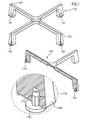
- a pot support 1000 may have four extensions that with a contact surface rest on a range, a hob or a flush-mounted hob in order to securely position a pot above a gas flame, for instance.
- elastic feet 1100, 1200, 1300 and 1400 are maintained.
- an access 1500, 1600 that shows where another example 1050 is cut.
- an elastic foot 1300 is shown, which may be of any elastic material and especially made of rubber because rubber is highly time-stable and undergoes no particular rapid aging.
- the rubber foot has a cylindrical portion which has a diameter 1770. The cylindrical portion is inserted into a stud hole 1750.
- a sidewall of the support structure 1800 is also shown.
- Fig. 2 shows a further detail of a pot support according to an embodiment of the present invention.
- the inventors have realized that secure connections between elastic feet and a support structure can be established without the use of glue.
- a bottom contact surface of the support structure 1800 is shown which is identified by reference sign 2000.
- a cavity in this case a bore or a stud hole is provided 2200, which has a first diameter 2100.
- a bolt 2300 can be seen which is e.g. built into the stud hole respectively cavity 2200 and may enter a hollow space within an elastic foot to expand it once it is inserted into the stud hole 2200.
- the elastic foot 1300 is shown, and its cylindrical portion has a distance 1850 to a top and of a stud hole. It is to be noted that the cavity where the elastic foot is inserted or supported does not have to be of a regular shape. On the other hand, it is easier to calculate a friction force between an elastic foot and a sidewall of the cavity built within a support structure in a predetermined manner in order to establish constant manufacturing conditions by providing feet and bores of a certain measurement relationship.
- FIG. 3 shows various examples of mounting an elastic foot to a support structure for forming a pot support are possible.
- the examples belonging to each other show various stages of the mounting process and those depicted above each other belong together to the same embodiment.
- a support structure 3110 is shown and an elastic foot 3120 is inserted into the support structure 3110.
- the elastic foot has a circular pad-shaped portion 3122 and a cylindrical barrel-shaped portion 3127 which is inserted e.g. into a cavity respectively bore or stud hole of the support structure 3110.
- glue 3130 is used to fix the foot 3120 in the support structure 3110.
- a development according to an embodiment of the present invention is shown.
- a bolt 3220 is shown in the support structure 3110.
- This bolt 3220 may e.g. be a nail.
- this bolt may be formed during the iron casting of the support structure 110 together with it.
- a foot 3230 is shown. It is inserted into a cavity 3225 and also features a hollow space 3240 that is here provided in a central symmetry axis and along with it. On the upper part, it can be seen that the bolt 3220 enters the hollow space 3240 of the foot and applies a pressure force to the elastic material in an area 3250. In this manner, the friction force between the elastic material in the area 3250 and applied to a sidewall of the cavity 3250 can be controlled by the dimensions of the bolt 3220 and dimensioned in such a manner that the foot 3230 will be reliably maintained by way of a press fit within the support structure 3110, no matter under which thermal conditions the pot support is operated and which thermal stress is created between the foot and the support structure.
- FIG. 3300 a similar example of an embodiment of the pot support according to the present invention is shown.
- the bolt is not fixed to the support structure 3110.
- the elastic foot 3330 is inserted into a cavity into the support structure 3110 as shown and later a bolt 3320 is inserted into a central hollow space 3340 provided along a symmetry axis within the elastic foot 3330.
- the elastic material will be pressed against the sidewall 3360 of the cavity in an area 3350 in order to securely fix the elastic foot to the support structure of the pot support.
- the insertion of bolt 3320 may be executed by means of a nail gun or a semi-automatic device or tool which increases the lead time in production lines over hand made processes.
- an elastic foot in a similar manner as in the previous examples 3430 having a hollow space 3440 is inserted into a support structure 3110.
- a rivet consisting of a central part 3450 and an outer hollow cylindrical part 3455 is inserted into the hollow space 3440.
- the cylindrical part 2455 is expanded in a manner that it presses the elastic material of the foot 3430 against the support structure 3110.
- the friction force between the support structure and the elastic foot 3430 can be exactly dimensioned in a manner that it is sufficient to maintain the elastic foot in position when the pot support is exposed to a usual temperature range in question for a kitchen hob or a range.
- the elastic foot shown in the example 3500 consists of a pad-shaped portion 3530 having a hollow space 3540 that is not inserted in the cavity or bore 3525.
- a rivet consisting of an interior part 3550 and a hollow cylindrical part 3555 is inserted through the hollow space 3540 and then expanded.
- the rivet is attached to a sidewall 3560 with its exterior part 3555.
- the hollow cylindrical part securely presses the pad-shaped portion of the elastic foot 3530 against a bottom surface of the support structure 3110.
Landscapes
- Engineering & Computer Science (AREA)
- Chemical & Material Sciences (AREA)
- Combustion & Propulsion (AREA)
- Mechanical Engineering (AREA)
- General Engineering & Computer Science (AREA)
- Cookers (AREA)
- Connection Of Plates (AREA)
Abstract
Description
- In modern kitchen environments and in particular where flush-mounted hobs or ranges are used, it is beneficial to use pot supports usually made of cast iron material in order to keep a predetermined distance between a pot or a pan to be supported above a gas burner. Those supports usually secure the proper distance between the bottom of the cooking vessel and the flame while at the same time promoting a proper placement of the pot regarding efficiency of the gas distribution underneath it.
- Usually cooking and preparing of food goes along with the spillage of fluids and thus, it is beneficial that pot supports can be removed in order to be cleaned. As a consequence, pot supports are usually centered around a gas burner and supported on a surface of a range or a hob or a workplate by elastic feet. The elastic feet provide proper dampening and rigid support of the pot support as well as thermal isolation between the surface on which they are positioned and the heat that is guided along the cast iron material of the pot support.
- Generally, the elastic feet of a pot support are mounted to it by using a glue. However, due to the constant thermal stress caused by different expansion coefficients of the cast iron material and the elastic material of which the foot consists due to the intermittent heating and cooling processes in the typical use case of a kitchen hob, the glue connection deteriorates over time. This leads to a problem that after some time the feet are no more properly maintained within the pot support. This on the other hand leads to a deteriorated quality impression by the customer.
- The German publication
DE 10 2005 046589 A1 shows a pot support having foot elements which are consisting of rubber and are inserted into a bore of a basic body of the pot support. - The invention is based on the problem to improve the quality impression of a pot support and in particular the fixing of a foot of a pot support.
- This problem is solved by the invention by a pot support according to claim 1 and by a method for mounting an elastic foot to a pot support according to claim 11.
- Further developments of the invention are given in the dependent claims.
- Advantageously, the pot support according to an embodiment of the present invention makes use of an expansion body that is inserted within an elastic foot in order to create a higher friction force between a cavity provided in the support structure and the elastic material of which the foot consists. In this manner, a secure connection between an elastic foot and the support structure of a pot support can be established without using glue. This has the advantage of a long-term stability of the mechanical connection as no chemical aging process takes place when such a structure is exposed to thermal stress. This is the case when a kitchen hob is used and a pot support is frequently heated and cooled down again due to the different thermal expansion coefficients of the elastic material and the usually used cast iron material of the support structure of the pot support.
- Beneficially, according to a further development of an embodiment of the pot support according to the present invention, the elastic foot cooperates with a bore or a stud hole having a different diameter.
- Beneficially, the first diameter of the stud hole of the bore being smaller than the second diameter of the elastic foot. In this manner, it is possible to secure an initial friction force between the walls of the bore respectively hole and the elastic foot that is then further increased by the expansion body.
- Favorably, according to a further development of an embodiment of the pot support according to the present invention, the expansion body is larger than the hollow space in a manner that creates the press fit at least between the expansion body and the elastic material next to the hollow space. In this manner, the friction force between an elastic foot and a support structure can be increased, e.g. adjusted to a value that guarantees a secure fixture of the elastic foot within or to the support structure.
- Beneficially, according to a further development of an embodiment of the pot support according to the present invention, the expansion body has the shape of a bolt. Bolts can easily be manufactured to a predefined diameter and are used in many industrial applications, which makes them cheap and reliable and widely available on the market. This renders them particularly suitable for an application in the household environment, which demands for reliability and availability as well as price performance.
- Beneficially, according to a further development of an embodiment of the pot support according to the present invention, the expansion body is fixed within the cavity. In this manner, the elastic foot gets expanded while it is inserted into the cavity and thus an additional manufacturing step during the process of fixing the elastic feet to the support structure can be saved, e.g. the bolts can be an integral part of the support structure and be e.g. cast together with it during the iron casting.
- Advantageously, according to a further development of an embodiment of the pot support according to the present invention, the expansion body can be constructed in the form of a rivet. Rivets are widely available on the market, and by selecting the dimension of a rivet, the final pressure between the elastic foot, the rivet, respectively the cavity or bore or hole can be exactly predetermined, once the rivet is in place. In this manner, it is possible to predetermine the friction force between the rivet, respectively the support structure, and the elastic foot.
- Beneficially, according to a further development of an embodiment of the pot support according to the present invention, the rivet is in direct contact with the bore, while on the other hand expanding the elastic foot on the outside of the support structure in order to fix it thereto. In this manner, a highly stable metal-to-metal connection between the rivet and the cast iron support structure can be established, which produces a higher friction force, while at the same time not suffering the complications of largely different thermal expansion coefficients, and thus withstands thermal stress a lot better than other designs used in the prior art.
- Advantageously, according to a further development of a pot support of the present invention, the elastic material is made of rubber. Rubber is a natural material and is highly stable over time and thus does not suffer deterioration of a rapid aging process giving thus a highly desired quality impression of the pot support to the customer.
- Advantageously, the method according to an embodiment of the present invention is suitable to fix an elastic foot to a pot support in a minimum number of steps without using glue, thereby in a unique way enhancing the friction force between the foot and the support structure in using an expansion body that is inserted into a hollow space of the foot and thus presses it against a cavity, respectively a bore provided in the support structure in the pot support. In this way, a reliable connection in form of a press fit can be established between the elastic foot and the support structure while omitting glue and the disadvantageous effects of glue, especially its aging as a consequence of thermal stress in heating and cooling and different expansion coefficients between a metallic respectively cast iron structure at a rubber respectively elastic material.
- Advantageously, according to a further development of an embodiment of the method of the present invention, the elastic material is pressed against a sidewall of a cavity. In this manner, the friction force can be more easily predetermined due to the known properties and dimensions of the sidewall respectively the elastic material as well as the expansion body. In this manner, the exact friction force can be efficiently predetermined and maintained during a manufacturing process.
- Advantageously, according to a further development of an embodiment of the method according to the present invention, the expansion body can be prefabricated within the cavity, e.g. by means of a bolt that expands the elastic material, once the foot is inserted within a bore, respectively cavity, respectively stud hole. In this manner, a highly facilitated manufacturing process can be realized.
- Advantageously, according to a further development of an embodiment of the method according to the present invention, the elastic foot can be pressed against a contact surface by the expansion body and thus secure a rigid connection between the support structure and the elastic foot, while at the same time within the cavity only a metal-to-metal contact is established.
- Beneficially, according to a further development of an embodiment of the method according to the present invention, a rivet is used that is inserted into the hollow space and the cavity once the two are aligned. In this manner, an easy manufacturing process can be realized that at the same time allows it to predetermine the final friction force between the rivet and the support structure in a manner that a proper dimensioning of the rivet can be performed by pre-selecting it according to rivet variants available on the market suitable for that purpose.
- Subsequently, the invention will be further explained on the basis of examples shown in drawings, wherein:
- Fig. 1
- shows a pot support;
- Fig. 2
- shows another view of a pot support; and
- Fig. 3
- shows a number of examples of feet secured to a pot support.
- As
Fig. 1 shows in a preferred embodiment, a pot support 1000 may have four extensions that with a contact surface rest on a range, a hob or a flush-mounted hob in order to securely position a pot above a gas flame, for instance. Within a support structure,elastic feet access detail view 1700, anelastic foot 1300 is shown, which may be of any elastic material and especially made of rubber because rubber is highly time-stable and undergoes no particular rapid aging. In this case, the rubber foot has a cylindrical portion which has adiameter 1770. The cylindrical portion is inserted into a stud hole 1750. Also shown is a sidewall of thesupport structure 1800. -
Fig. 2 shows a further detail of a pot support according to an embodiment of the present invention. In particular, the inventors have realized that secure connections between elastic feet and a support structure can be established without the use of glue. Here, a bottom contact surface of thesupport structure 1800 is shown which is identified byreference sign 2000. Within the support structure, a cavity, in this case a bore or a stud hole is provided 2200, which has afirst diameter 2100. Also abolt 2300 can be seen which is e.g. built into the stud hole respectivelycavity 2200 and may enter a hollow space within an elastic foot to expand it once it is inserted into thestud hole 2200. In an enlargedview 1700, theelastic foot 1300 is shown, and its cylindrical portion has adistance 1850 to a top and of a stud hole. It is to be noted that the cavity where the elastic foot is inserted or supported does not have to be of a regular shape. On the other hand, it is easier to calculate a friction force between an elastic foot and a sidewall of the cavity built within a support structure in a predetermined manner in order to establish constant manufacturing conditions by providing feet and bores of a certain measurement relationship. - As
Fig. 3 shows various examples of mounting an elastic foot to a support structure for forming a pot support are possible. The examples belonging to each other show various stages of the mounting process and those depicted above each other belong together to the same embodiment. In the example 3100, asupport structure 3110 is shown and anelastic foot 3120 is inserted into thesupport structure 3110. The elastic foot has a circular pad-shapedportion 3122 and a cylindrical barrel-shapedportion 3127 which is inserted e.g. into a cavity respectively bore or stud hole of thesupport structure 3110. In case of the prior art example shown here,glue 3130 is used to fix thefoot 3120 in thesupport structure 3110. - In another example 3200, a development according to an embodiment of the present invention is shown. Here, in the
support structure 3110, abolt 3220 is shown. Thisbolt 3220 may e.g. be a nail. On the other hand, this bolt may be formed during the iron casting of the support structure 110 together with it. - Further below, a
foot 3230 is shown. It is inserted into acavity 3225 and also features ahollow space 3240 that is here provided in a central symmetry axis and along with it. On the upper part, it can be seen that thebolt 3220 enters thehollow space 3240 of the foot and applies a pressure force to the elastic material in anarea 3250. In this manner, the friction force between the elastic material in thearea 3250 and applied to a sidewall of thecavity 3250 can be controlled by the dimensions of thebolt 3220 and dimensioned in such a manner that thefoot 3230 will be reliably maintained by way of a press fit within thesupport structure 3110, no matter under which thermal conditions the pot support is operated and which thermal stress is created between the foot and the support structure. - At 3300, a similar example of an embodiment of the pot support according to the present invention is shown. Here, the bolt is not fixed to the
support structure 3110. Theelastic foot 3330 is inserted into a cavity into thesupport structure 3110 as shown and later abolt 3320 is inserted into a centralhollow space 3340 provided along a symmetry axis within theelastic foot 3330. In this manner, using thebolt 3320 as an expansion body, the elastic material will be pressed against thesidewall 3360 of the cavity in anarea 3350 in order to securely fix the elastic foot to the support structure of the pot support. The insertion ofbolt 3320 may be executed by means of a nail gun or a semi-automatic device or tool which increases the lead time in production lines over hand made processes. - In another example of the pot support according to a further development of an embodiment of the
present invention 3400, an elastic foot in a similar manner as in the previous examples 3430 having ahollow space 3440 is inserted into asupport structure 3110. In this case, however, a rivet consisting of acentral part 3450 and an outer hollowcylindrical part 3455 is inserted into thehollow space 3440. As further shown, the cylindrical part 2455 is expanded in a manner that it presses the elastic material of thefoot 3430 against thesupport structure 3110. - By dimensioning the rivet according to the desired pressure after fixing it, the friction force between the support structure and the
elastic foot 3430 can be exactly dimensioned in a manner that it is sufficient to maintain the elastic foot in position when the pot support is exposed to a usual temperature range in question for a kitchen hob or a range. - In a further development of an embodiment according to the present invention, the elastic foot shown in the example 3500 consists of a pad-shaped
portion 3530 having ahollow space 3540 that is not inserted in the cavity orbore 3525. In this case, also a rivet consisting of aninterior part 3550 and a hollowcylindrical part 3555 is inserted through thehollow space 3540 and then expanded. Here, as shown further below, the rivet is attached to asidewall 3560 with itsexterior part 3555. On the other hand, the hollow cylindrical part securely presses the pad-shaped portion of theelastic foot 3530 against a bottom surface of thesupport structure 3110. Thus, as shown above, various possibilities exist to fix and mount an elastic foot to a support structure of a pot support, respectively pan support. -
- 1000
- pot support;
- 1100, 1200, 1300, 1400
- elastic feet;
- 1500, 1600
- cut axis
- 1050
- cut support structure;
- 1700
- detailed enlarged view;
- 1800
- support structure;
- 1770
- diameter of cylindrical part of elastic foot
- 1750
- cavity;
- 2000
- bottom contact surface of support structure;
- 2100
- diameter of cavity;
- 2200
- cavity;
- 2300
- expansion body;
- 1850
- distance between top end of foot and top end of stud hole;
- 3100
- prior art;
- 3110
- support structure;
- 3120
- elastic foot;
- 3122
- pad-shaped portion of elastic foot;
- 3140
- glue;
- 3130
- glue;
- 3127
- cylindrical portion of elastic foot;
- 3200
- other development;
- 3220
- bolt;
- 3225
- sidewall of hole/bore;
- 3250
- press-fit area;
- 3240
- hollow space;
- 3230
- pad-shaped portion of elastic foot;
- 3300
- further example;
- 3330
- elastic foot;
- 3320
- bolt;
- 3340
- hollow space;
- 3400
- other example;
- 3440
- hollow space;
- 3430
- pad-shaped portion of elastic foot;
- 3455
- cylindrical portion of rivet;
- 3450
- bolt portion of rivet;
- 3500
- other example;
- 3525
- bore:
- 3535
- pad-shaped portion of elastic foot;
- 3540
- hollow space;
- 3555
- hollow cylindrical portion of rivet;
- 3550
- bolt portion of rivet;
- 3560
- sidewall of bore in
support structure 3110.
Claims (15)
- Pot support (1000) with elastic foot (1300), comprising:- a support structure (1000);- a contact surface (2000);- a cavity (3200) within the support structure accessible through the contact surface;- a foot (1300) made from elastic material comprising a hollow space (3240) extending into the cavity; and- an expansion body (3220, 3450) within the cavity (3200) and the hollow space (3240).
- Pot support (1000) according to claim 1, wherein the cavity (2200) is a stud hole or a bore having a first diameter (2100), the foot (1300) having a second diameter (1770).
- Pot support (1000) according to claim 2, wherein the second diameter (1770) is larger than the first diameter (2100).
- Pot support (1000) according to any one of the previous claims, wherein the expansion body (3220, 3450) is larger than the hollow space (3240), thus establishing at least a press fit of the elastic material.
- Pot support (1000) according to any one of the previous claims, wherein the expansion body is a bolt (3220, 3520).
- Pot support (1000) according to any one of the previous claims, wherein the expansion body (3220, 3520) is fixed within the cavity (2200).
- Pot support (1000) according to any one of the claims 1 to 4, wherein the expansion body (3450, 3550) is a rivet.
- Pot support (1000) according to claim 7, wherein the expansion body is a rivet (3550) and the foot (1300) is not extending into the cavity (2200).
- Pot support (1000) according to claim 8, wherein the rivet (3550) directly contacts a wall (3560) of the cavity.
- Pot support (1000) according to any one of the previous claims, wherein the elastic material is rubber.
- Method for mounting an elastic foot (1300) to a pot support (1000), wherein:- in a first step, a hollow space (3240) of a foot (1300) and a cavity (2200) of a pot support (1000) are aligned; and- in a second step, an expansion body (3220, 3450) is inserted into the hollow space (3240) to form a press fit with the foot (1300).
- Method according to claim 11, wherein the elastic material is pressed against a sidewall (3560) of the cavity (2200).
- Method according to any of the claims 11 to 12, wherein the elastic material is expanded by a bolt (2220) fixed inside the cavity, when the foot (1300) is inserted into the cavity (2200).
- Method according to claim 11, wherein the foot (1300) is pressed against the contact surface by the expansion body (3550).
- Method according to claims 12 or 14, wherein the expansion body is a rivet (3450, 3550) that is fixed after cavity (2200) and hollow space (3240) have been aligned.
Priority Applications (7)
| Application Number | Priority Date | Filing Date | Title |
|---|---|---|---|
| ES14167282.4T ES2657958T3 (en) | 2014-05-07 | 2014-05-07 | Pan holder with elastic foot and method to fix the elastic foot in a pan holder |
| EP14167282.4A EP2942568B1 (en) | 2014-05-07 | 2014-05-07 | Pot support with elastic foot and method for fixing elastic foot to a pot support |
| AU2015257964A AU2015257964B2 (en) | 2014-05-07 | 2015-04-28 | Pot support with elastic foot and method for fixing elastic foot to a pot support |
| BR112016022119-2A BR112016022119B1 (en) | 2014-05-07 | 2015-04-28 | support for pots with elastic feet and method for mounting an elastic foot on a pot support |
| PCT/EP2015/059160 WO2015169638A1 (en) | 2014-05-07 | 2015-04-28 | Pot support with elastic foot and method for fixing elastic foot to a pot support |
| US15/119,925 US10533753B2 (en) | 2014-05-07 | 2015-04-28 | Pot support with elastic foot and method for fixing elastic foot to a pot support |
| CN201580013872.4A CN106104162A (en) | 2014-05-07 | 2015-04-28 | Saucepan support with elastic feet and method of securing elastic feet to saucepan support |
Applications Claiming Priority (1)
| Application Number | Priority Date | Filing Date | Title |
|---|---|---|---|
| EP14167282.4A EP2942568B1 (en) | 2014-05-07 | 2014-05-07 | Pot support with elastic foot and method for fixing elastic foot to a pot support |
Publications (2)
| Publication Number | Publication Date |
|---|---|
| EP2942568A1 true EP2942568A1 (en) | 2015-11-11 |
| EP2942568B1 EP2942568B1 (en) | 2017-11-08 |
Family
ID=50639350
Family Applications (1)
| Application Number | Title | Priority Date | Filing Date |
|---|---|---|---|
| EP14167282.4A Active EP2942568B1 (en) | 2014-05-07 | 2014-05-07 | Pot support with elastic foot and method for fixing elastic foot to a pot support |
Country Status (7)
| Country | Link |
|---|---|
| US (1) | US10533753B2 (en) |
| EP (1) | EP2942568B1 (en) |
| CN (1) | CN106104162A (en) |
| AU (1) | AU2015257964B2 (en) |
| BR (1) | BR112016022119B1 (en) |
| ES (1) | ES2657958T3 (en) |
| WO (1) | WO2015169638A1 (en) |
Families Citing this family (11)
| Publication number | Priority date | Publication date | Assignee | Title |
|---|---|---|---|---|
| ES2668345T3 (en) * | 2015-02-25 | 2018-05-17 | Electrolux Appliances Aktiebolag | Rubber foot for metal device that can be heated |
| CN106402960B (en) * | 2016-11-30 | 2019-06-04 | 成都前锋电子有限责任公司 | A kind of sunk type kitchen range for preventing pot from sliding |
| US11149957B2 (en) * | 2017-12-18 | 2021-10-19 | Hestan Commercial Corporation | Cooking vessel support grate |
| US11963636B2 (en) * | 2018-10-26 | 2024-04-23 | Loco—Crazy Good Cookers, Inc. | Turkey cooking device |
| US11925360B2 (en) * | 2018-11-02 | 2024-03-12 | Conmed Corporation | Method for preventing kinked tubing in an arthroscopic irrigation pump |
| KR102257991B1 (en) * | 2020-07-30 | 2021-05-28 | 주식회사 키오떼이앤씨 | Cooking apparatus with fixed pedestal |
| US11859829B2 (en) | 2021-12-03 | 2024-01-02 | Whirlpool Corporation | Cooktop grate assembly |
| WO2023128921A1 (en) * | 2021-12-31 | 2023-07-06 | Mamur Teknoloji Sistemleri San. A.S. | A gas cooker with a pan support |
| US12234994B2 (en) * | 2022-04-05 | 2025-02-25 | Whirlpool Corporation | Cooktop grate support |
| US12359817B2 (en) | 2022-08-11 | 2025-07-15 | Solo Brands, Llc | Portable stove with folding stand |
| USD1043934S1 (en) | 2022-08-11 | 2024-09-24 | Solo Brands, Llc | Fire pit and stand |
Citations (10)
| Publication number | Priority date | Publication date | Assignee | Title |
|---|---|---|---|---|
| WO2004023043A1 (en) * | 2002-09-09 | 2004-03-18 | Lino Cavicchioli | Cooker grid |
| JP2004150670A (en) * | 2002-10-29 | 2004-05-27 | Rinnai Corp | Grate |
| DE102005046589A1 (en) | 2005-09-28 | 2007-03-29 | BSH Bosch und Siemens Hausgeräte GmbH | Individual pot support arrangement for gas burner area, has aligning units corresponding to predetermined areas of support and heat shield, and provided for arrangement of support at shield, where spigots are designed as aligning units |
| EP2048445A2 (en) * | 2007-10-09 | 2009-04-15 | Kenyon International, Inc | Safety system for a stove |
| WO2009121598A1 (en) * | 2008-04-04 | 2009-10-08 | Aktiebolaget Electrolux (Publ) | A trivet |
| DE202010010785U1 (en) * | 2010-06-24 | 2010-11-11 | BSH Bosch und Siemens Hausgeräte GmbH | Compliant, stabilizing pot sill foot |
| EP2253889A1 (en) * | 2009-05-22 | 2010-11-24 | BSH Bosch und Siemens Hausgeräte GmbH | Pot holder for gas oven and gas oven with same |
| JP2011002181A (en) * | 2009-06-19 | 2011-01-06 | Rinnai Corp | Glass top stove |
| US20120048258A1 (en) * | 2010-08-31 | 2012-03-01 | Bsh Home Appliances Corporation | Adjustable grate foot for home appliance |
| DE102012214855A1 (en) * | 2012-08-21 | 2014-02-27 | BSH Bosch und Siemens Hausgeräte GmbH | Gas burner for cooktop arrangement, has burner throat including receptacle for receiving burner cap so that annular portion of burner throat encloses burner cap, where burner cap is flush with upper side of annular portion of burner throat |
Family Cites Families (15)
| Publication number | Priority date | Publication date | Assignee | Title |
|---|---|---|---|---|
| US1356797A (en) * | 1916-04-10 | 1920-10-26 | Stock Nicholas | Chair-tip |
| US1843261A (en) * | 1929-06-24 | 1932-02-02 | Lyon Metal Products Inc | Furniture foot |
| US2764970A (en) * | 1952-08-18 | 1956-10-02 | Attilio D Carani | Adapter for stove burner grills |
| US2849201A (en) * | 1953-10-07 | 1958-08-26 | Bird Electronic Corp | Resilient foot for instruments and the like |
| US3266446A (en) * | 1964-10-13 | 1966-08-16 | Raymond Haydock Jr | Patio tray leg clip |
| US5153052A (en) * | 1987-11-27 | 1992-10-06 | Nifco, Inc. | Double-shot molded resin article |
| JPH01151740U (en) * | 1988-04-04 | 1989-10-19 | ||
| US5007607A (en) * | 1988-12-30 | 1991-04-16 | Samsung Electronics Co., Ltd. | Support unit for home appliances |
| US6563553B1 (en) * | 1997-01-16 | 2003-05-13 | Reveo, Inc. | Flat panel display and method of manufacture |
| US6407351B1 (en) * | 1999-09-29 | 2002-06-18 | Premark Feg L.L.C. | Thread covering assembly for adjustable support feet and the like |
| CA2596512A1 (en) * | 2005-03-01 | 2006-09-08 | Max-Tech Products, Inc. | Glide device and article of furniture incorporating the same |
| JP4955445B2 (en) * | 2007-04-16 | 2012-06-20 | ポリマテック株式会社 | Damper, electronic component and electronic device equipped with damper |
| US20090044795A1 (en) * | 2007-08-17 | 2009-02-19 | Timothy Scott Shaffer | Grate apparatus and method of cleaning |
| CN201811317U (en) | 2010-07-23 | 2011-04-27 | 宁波方太厨具有限公司 | Pointed pot bracket with cushion pad at bottom |
| ES2621792T3 (en) * | 2011-11-04 | 2017-07-05 | Electrolux Home Products Corporation N.V. | Gas burner set, gas hob and appliance with gas burners |
-
2014
- 2014-05-07 EP EP14167282.4A patent/EP2942568B1/en active Active
- 2014-05-07 ES ES14167282.4T patent/ES2657958T3/en active Active
-
2015
- 2015-04-28 US US15/119,925 patent/US10533753B2/en active Active
- 2015-04-28 BR BR112016022119-2A patent/BR112016022119B1/en active IP Right Grant
- 2015-04-28 AU AU2015257964A patent/AU2015257964B2/en not_active Ceased
- 2015-04-28 WO PCT/EP2015/059160 patent/WO2015169638A1/en not_active Ceased
- 2015-04-28 CN CN201580013872.4A patent/CN106104162A/en active Pending
Patent Citations (10)
| Publication number | Priority date | Publication date | Assignee | Title |
|---|---|---|---|---|
| WO2004023043A1 (en) * | 2002-09-09 | 2004-03-18 | Lino Cavicchioli | Cooker grid |
| JP2004150670A (en) * | 2002-10-29 | 2004-05-27 | Rinnai Corp | Grate |
| DE102005046589A1 (en) | 2005-09-28 | 2007-03-29 | BSH Bosch und Siemens Hausgeräte GmbH | Individual pot support arrangement for gas burner area, has aligning units corresponding to predetermined areas of support and heat shield, and provided for arrangement of support at shield, where spigots are designed as aligning units |
| EP2048445A2 (en) * | 2007-10-09 | 2009-04-15 | Kenyon International, Inc | Safety system for a stove |
| WO2009121598A1 (en) * | 2008-04-04 | 2009-10-08 | Aktiebolaget Electrolux (Publ) | A trivet |
| EP2253889A1 (en) * | 2009-05-22 | 2010-11-24 | BSH Bosch und Siemens Hausgeräte GmbH | Pot holder for gas oven and gas oven with same |
| JP2011002181A (en) * | 2009-06-19 | 2011-01-06 | Rinnai Corp | Glass top stove |
| DE202010010785U1 (en) * | 2010-06-24 | 2010-11-11 | BSH Bosch und Siemens Hausgeräte GmbH | Compliant, stabilizing pot sill foot |
| US20120048258A1 (en) * | 2010-08-31 | 2012-03-01 | Bsh Home Appliances Corporation | Adjustable grate foot for home appliance |
| DE102012214855A1 (en) * | 2012-08-21 | 2014-02-27 | BSH Bosch und Siemens Hausgeräte GmbH | Gas burner for cooktop arrangement, has burner throat including receptacle for receiving burner cap so that annular portion of burner throat encloses burner cap, where burner cap is flush with upper side of annular portion of burner throat |
Also Published As
| Publication number | Publication date |
|---|---|
| EP2942568B1 (en) | 2017-11-08 |
| US10533753B2 (en) | 2020-01-14 |
| US20170059178A1 (en) | 2017-03-02 |
| ES2657958T3 (en) | 2018-03-07 |
| BR112016022119B1 (en) | 2021-02-02 |
| CN106104162A (en) | 2016-11-09 |
| AU2015257964A1 (en) | 2016-09-01 |
| WO2015169638A1 (en) | 2015-11-12 |
| AU2015257964B2 (en) | 2019-10-03 |
Similar Documents
| Publication | Publication Date | Title |
|---|---|---|
| US10533753B2 (en) | Pot support with elastic foot and method for fixing elastic foot to a pot support | |
| US10655845B2 (en) | Gas burner and gas cooktop | |
| US20120048258A1 (en) | Adjustable grate foot for home appliance | |
| US10616961B2 (en) | Side wire rack fixing device for a cooking appliance with microwave heating function | |
| CN1780705A (en) | Method for producing in particular pots, pans or similar cooking utensils and cooking utensils produced by this method | |
| EP2238390A1 (en) | A cooktop | |
| KR100745028B1 (en) | Cookware for Induction Heater and Manufacturing Method Thereof | |
| KR101088894B1 (en) | Manufacturing method of container for electronic cooker | |
| FR2866537A1 (en) | Bake unit for steamer, has perforated base with openwork plate obtained by deformation of metal plate and parts having tongues, fixed to plate after pressing operation, where plate`s radial section contacts one elongated conformation | |
| WO2009083390A1 (en) | An oven | |
| EP3249305B1 (en) | Gas stove | |
| JP2018073919A (en) | Holding device and manufacturing method thereof | |
| CN219713430U (en) | Stove plate fixing structure of microcrystalline stove | |
| EP3317548B1 (en) | Screw connection | |
| KR102114986B1 (en) | Pipe forming device and manufacturing method of distribution pipe using this device | |
| WO2015039842A1 (en) | A cooker comprising a cast iron burner plate | |
| CN109237553B (en) | Hot plate device with hot plate and furnace frame | |
| KR101274727B1 (en) | The top board of gas range | |
| CN204427656U (en) | Pressure cooker | |
| JP3203199U (en) | Auxiliary heating tool | |
| JP6872967B2 (en) | Gas burner | |
| WO2011073162A1 (en) | An oven comprising a burner | |
| KR20150125261A (en) | Roasting Grill | |
| KR100696862B1 (en) | Roasting | |
| KR20160136598A (en) | Roasting Grill |
Legal Events
| Date | Code | Title | Description |
|---|---|---|---|
| PUAI | Public reference made under article 153(3) epc to a published international application that has entered the european phase |
Free format text: ORIGINAL CODE: 0009012 |
|
| AK | Designated contracting states |
Kind code of ref document: A1 Designated state(s): AL AT BE BG CH CY CZ DE DK EE ES FI FR GB GR HR HU IE IS IT LI LT LU LV MC MK MT NL NO PL PT RO RS SE SI SK SM TR |
|
| AX | Request for extension of the european patent |
Extension state: BA ME |
|
| 17P | Request for examination filed |
Effective date: 20160511 |
|
| RBV | Designated contracting states (corrected) |
Designated state(s): AL AT BE BG CH CY CZ DE DK EE ES FI FR GB GR HR HU IE IS IT LI LT LU LV MC MK MT NL NO PL PT RO RS SE SI SK SM TR |
|
| 17Q | First examination report despatched |
Effective date: 20170126 |
|
| REG | Reference to a national code |
Ref country code: DE Ref legal event code: R079 Ref document number: 602014016799 Country of ref document: DE Free format text: PREVIOUS MAIN CLASS: F24C0015100000 Ipc: A47B0091040000 |
|
| GRAP | Despatch of communication of intention to grant a patent |
Free format text: ORIGINAL CODE: EPIDOSNIGR1 |
|
| RIC1 | Information provided on ipc code assigned before grant |
Ipc: F24C 15/10 20060101ALI20170530BHEP Ipc: A47B 91/04 20060101AFI20170530BHEP |
|
| INTG | Intention to grant announced |
Effective date: 20170620 |
|
| GRAS | Grant fee paid |
Free format text: ORIGINAL CODE: EPIDOSNIGR3 |
|
| GRAA | (expected) grant |
Free format text: ORIGINAL CODE: 0009210 |
|
| AK | Designated contracting states |
Kind code of ref document: B1 Designated state(s): AL AT BE BG CH CY CZ DE DK EE ES FI FR GB GR HR HU IE IS IT LI LT LU LV MC MK MT NL NO PL PT RO RS SE SI SK SM TR |
|
| REG | Reference to a national code |
Ref country code: GB Ref legal event code: FG4D |
|
| REG | Reference to a national code |
Ref country code: CH Ref legal event code: EP Ref country code: AT Ref legal event code: REF Ref document number: 943336 Country of ref document: AT Kind code of ref document: T Effective date: 20171115 |
|
| REG | Reference to a national code |
Ref country code: IE Ref legal event code: FG4D |
|
| REG | Reference to a national code |
Ref country code: DE Ref legal event code: R096 Ref document number: 602014016799 Country of ref document: DE |
|
| REG | Reference to a national code |
Ref country code: ES Ref legal event code: FG2A Ref document number: 2657958 Country of ref document: ES Kind code of ref document: T3 Effective date: 20180307 |
|
| REG | Reference to a national code |
Ref country code: NL Ref legal event code: MP Effective date: 20171108 |
|
| REG | Reference to a national code |
Ref country code: LT Ref legal event code: MG4D |
|
| REG | Reference to a national code |
Ref country code: AT Ref legal event code: MK05 Ref document number: 943336 Country of ref document: AT Kind code of ref document: T Effective date: 20171108 |
|
| PG25 | Lapsed in a contracting state [announced via postgrant information from national office to epo] |
Ref country code: NO Free format text: LAPSE BECAUSE OF FAILURE TO SUBMIT A TRANSLATION OF THE DESCRIPTION OR TO PAY THE FEE WITHIN THE PRESCRIBED TIME-LIMIT Effective date: 20180208 Ref country code: LT Free format text: LAPSE BECAUSE OF FAILURE TO SUBMIT A TRANSLATION OF THE DESCRIPTION OR TO PAY THE FEE WITHIN THE PRESCRIBED TIME-LIMIT Effective date: 20171108 Ref country code: FI Free format text: LAPSE BECAUSE OF FAILURE TO SUBMIT A TRANSLATION OF THE DESCRIPTION OR TO PAY THE FEE WITHIN THE PRESCRIBED TIME-LIMIT Effective date: 20171108 Ref country code: SE Free format text: LAPSE BECAUSE OF FAILURE TO SUBMIT A TRANSLATION OF THE DESCRIPTION OR TO PAY THE FEE WITHIN THE PRESCRIBED TIME-LIMIT Effective date: 20171108 Ref country code: NL Free format text: LAPSE BECAUSE OF FAILURE TO SUBMIT A TRANSLATION OF THE DESCRIPTION OR TO PAY THE FEE WITHIN THE PRESCRIBED TIME-LIMIT Effective date: 20171108 |
|
| REG | Reference to a national code |
Ref country code: FR Ref legal event code: PLFP Year of fee payment: 5 |
|
| PG25 | Lapsed in a contracting state [announced via postgrant information from national office to epo] |
Ref country code: AT Free format text: LAPSE BECAUSE OF FAILURE TO SUBMIT A TRANSLATION OF THE DESCRIPTION OR TO PAY THE FEE WITHIN THE PRESCRIBED TIME-LIMIT Effective date: 20171108 Ref country code: RS Free format text: LAPSE BECAUSE OF FAILURE TO SUBMIT A TRANSLATION OF THE DESCRIPTION OR TO PAY THE FEE WITHIN THE PRESCRIBED TIME-LIMIT Effective date: 20171108 Ref country code: GR Free format text: LAPSE BECAUSE OF FAILURE TO SUBMIT A TRANSLATION OF THE DESCRIPTION OR TO PAY THE FEE WITHIN THE PRESCRIBED TIME-LIMIT Effective date: 20180209 Ref country code: HR Free format text: LAPSE BECAUSE OF FAILURE TO SUBMIT A TRANSLATION OF THE DESCRIPTION OR TO PAY THE FEE WITHIN THE PRESCRIBED TIME-LIMIT Effective date: 20171108 Ref country code: IS Free format text: LAPSE BECAUSE OF FAILURE TO SUBMIT A TRANSLATION OF THE DESCRIPTION OR TO PAY THE FEE WITHIN THE PRESCRIBED TIME-LIMIT Effective date: 20180308 Ref country code: LV Free format text: LAPSE BECAUSE OF FAILURE TO SUBMIT A TRANSLATION OF THE DESCRIPTION OR TO PAY THE FEE WITHIN THE PRESCRIBED TIME-LIMIT Effective date: 20171108 Ref country code: BG Free format text: LAPSE BECAUSE OF FAILURE TO SUBMIT A TRANSLATION OF THE DESCRIPTION OR TO PAY THE FEE WITHIN THE PRESCRIBED TIME-LIMIT Effective date: 20180208 |
|
| PG25 | Lapsed in a contracting state [announced via postgrant information from national office to epo] |
Ref country code: CZ Free format text: LAPSE BECAUSE OF FAILURE TO SUBMIT A TRANSLATION OF THE DESCRIPTION OR TO PAY THE FEE WITHIN THE PRESCRIBED TIME-LIMIT Effective date: 20171108 Ref country code: SK Free format text: LAPSE BECAUSE OF FAILURE TO SUBMIT A TRANSLATION OF THE DESCRIPTION OR TO PAY THE FEE WITHIN THE PRESCRIBED TIME-LIMIT Effective date: 20171108 Ref country code: EE Free format text: LAPSE BECAUSE OF FAILURE TO SUBMIT A TRANSLATION OF THE DESCRIPTION OR TO PAY THE FEE WITHIN THE PRESCRIBED TIME-LIMIT Effective date: 20171108 Ref country code: CY Free format text: LAPSE BECAUSE OF FAILURE TO SUBMIT A TRANSLATION OF THE DESCRIPTION OR TO PAY THE FEE WITHIN THE PRESCRIBED TIME-LIMIT Effective date: 20171108 Ref country code: DK Free format text: LAPSE BECAUSE OF FAILURE TO SUBMIT A TRANSLATION OF THE DESCRIPTION OR TO PAY THE FEE WITHIN THE PRESCRIBED TIME-LIMIT Effective date: 20171108 |
|
| REG | Reference to a national code |
Ref country code: DE Ref legal event code: R097 Ref document number: 602014016799 Country of ref document: DE |
|
| PG25 | Lapsed in a contracting state [announced via postgrant information from national office to epo] |
Ref country code: RO Free format text: LAPSE BECAUSE OF FAILURE TO SUBMIT A TRANSLATION OF THE DESCRIPTION OR TO PAY THE FEE WITHIN THE PRESCRIBED TIME-LIMIT Effective date: 20171108 Ref country code: PL Free format text: LAPSE BECAUSE OF FAILURE TO SUBMIT A TRANSLATION OF THE DESCRIPTION OR TO PAY THE FEE WITHIN THE PRESCRIBED TIME-LIMIT Effective date: 20171108 Ref country code: SM Free format text: LAPSE BECAUSE OF FAILURE TO SUBMIT A TRANSLATION OF THE DESCRIPTION OR TO PAY THE FEE WITHIN THE PRESCRIBED TIME-LIMIT Effective date: 20171108 |
|
| PLBE | No opposition filed within time limit |
Free format text: ORIGINAL CODE: 0009261 |
|
| STAA | Information on the status of an ep patent application or granted ep patent |
Free format text: STATUS: NO OPPOSITION FILED WITHIN TIME LIMIT |
|
| 26N | No opposition filed |
Effective date: 20180809 |
|
| PG25 | Lapsed in a contracting state [announced via postgrant information from national office to epo] |
Ref country code: SI Free format text: LAPSE BECAUSE OF FAILURE TO SUBMIT A TRANSLATION OF THE DESCRIPTION OR TO PAY THE FEE WITHIN THE PRESCRIBED TIME-LIMIT Effective date: 20171108 |
|
| REG | Reference to a national code |
Ref country code: DE Ref legal event code: R119 Ref document number: 602014016799 Country of ref document: DE |
|
| REG | Reference to a national code |
Ref country code: CH Ref legal event code: PL |
|
| REG | Reference to a national code |
Ref country code: BE Ref legal event code: MM Effective date: 20180531 |
|
| PG25 | Lapsed in a contracting state [announced via postgrant information from national office to epo] |
Ref country code: MC Free format text: LAPSE BECAUSE OF FAILURE TO SUBMIT A TRANSLATION OF THE DESCRIPTION OR TO PAY THE FEE WITHIN THE PRESCRIBED TIME-LIMIT Effective date: 20171108 |
|
| REG | Reference to a national code |
Ref country code: IE Ref legal event code: MM4A |
|
| PG25 | Lapsed in a contracting state [announced via postgrant information from national office to epo] |
Ref country code: LI Free format text: LAPSE BECAUSE OF NON-PAYMENT OF DUE FEES Effective date: 20180531 Ref country code: CH Free format text: LAPSE BECAUSE OF NON-PAYMENT OF DUE FEES Effective date: 20180531 |
|
| PG25 | Lapsed in a contracting state [announced via postgrant information from national office to epo] |
Ref country code: LU Free format text: LAPSE BECAUSE OF NON-PAYMENT OF DUE FEES Effective date: 20180507 |
|
| PG25 | Lapsed in a contracting state [announced via postgrant information from national office to epo] |
Ref country code: IE Free format text: LAPSE BECAUSE OF NON-PAYMENT OF DUE FEES Effective date: 20180507 Ref country code: DE Free format text: LAPSE BECAUSE OF NON-PAYMENT OF DUE FEES Effective date: 20181201 |
|
| PG25 | Lapsed in a contracting state [announced via postgrant information from national office to epo] |
Ref country code: BE Free format text: LAPSE BECAUSE OF NON-PAYMENT OF DUE FEES Effective date: 20180531 |
|
| PG25 | Lapsed in a contracting state [announced via postgrant information from national office to epo] |
Ref country code: MT Free format text: LAPSE BECAUSE OF NON-PAYMENT OF DUE FEES Effective date: 20180507 |
|
| PG25 | Lapsed in a contracting state [announced via postgrant information from national office to epo] |
Ref country code: TR Free format text: LAPSE BECAUSE OF FAILURE TO SUBMIT A TRANSLATION OF THE DESCRIPTION OR TO PAY THE FEE WITHIN THE PRESCRIBED TIME-LIMIT Effective date: 20171108 |
|
| PG25 | Lapsed in a contracting state [announced via postgrant information from national office to epo] |
Ref country code: PT Free format text: LAPSE BECAUSE OF FAILURE TO SUBMIT A TRANSLATION OF THE DESCRIPTION OR TO PAY THE FEE WITHIN THE PRESCRIBED TIME-LIMIT Effective date: 20171108 |
|
| PG25 | Lapsed in a contracting state [announced via postgrant information from national office to epo] |
Ref country code: MK Free format text: LAPSE BECAUSE OF NON-PAYMENT OF DUE FEES Effective date: 20171108 Ref country code: HU Free format text: LAPSE BECAUSE OF FAILURE TO SUBMIT A TRANSLATION OF THE DESCRIPTION OR TO PAY THE FEE WITHIN THE PRESCRIBED TIME-LIMIT; INVALID AB INITIO Effective date: 20140507 |
|
| PG25 | Lapsed in a contracting state [announced via postgrant information from national office to epo] |
Ref country code: AL Free format text: LAPSE BECAUSE OF FAILURE TO SUBMIT A TRANSLATION OF THE DESCRIPTION OR TO PAY THE FEE WITHIN THE PRESCRIBED TIME-LIMIT Effective date: 20171108 |
|
| P01 | Opt-out of the competence of the unified patent court (upc) registered |
Effective date: 20230625 |
|
| PGFP | Annual fee paid to national office [announced via postgrant information from national office to epo] |
Ref country code: GB Payment date: 20250520 Year of fee payment: 12 Ref country code: ES Payment date: 20250611 Year of fee payment: 12 |
|
| PGFP | Annual fee paid to national office [announced via postgrant information from national office to epo] |
Ref country code: IT Payment date: 20250522 Year of fee payment: 12 |
|
| PGFP | Annual fee paid to national office [announced via postgrant information from national office to epo] |
Ref country code: FR Payment date: 20250526 Year of fee payment: 12 |