EP2942322A1 - Machine de remplissage de récipient avec une meilleure détection d'un niveau de remplissage et procédé associé - Google Patents
Machine de remplissage de récipient avec une meilleure détection d'un niveau de remplissage et procédé associé Download PDFInfo
- Publication number
- EP2942322A1 EP2942322A1 EP14167450.7A EP14167450A EP2942322A1 EP 2942322 A1 EP2942322 A1 EP 2942322A1 EP 14167450 A EP14167450 A EP 14167450A EP 2942322 A1 EP2942322 A1 EP 2942322A1
- Authority
- EP
- European Patent Office
- Prior art keywords
- container
- filling
- unit
- laser
- product
- Prior art date
- Legal status (The legal status is an assumption and is not a legal conclusion. Google has not performed a legal analysis and makes no representation as to the accuracy of the status listed.)
- Granted
Links
- 238000000034 method Methods 0.000 title claims description 13
- 238000012545 processing Methods 0.000 claims description 11
- 239000012530 fluid Substances 0.000 claims description 9
- 238000005305 interferometry Methods 0.000 claims description 6
- 238000002156 mixing Methods 0.000 claims description 5
- 238000004891 communication Methods 0.000 claims description 4
- 238000012544 monitoring process Methods 0.000 claims 2
- 230000003287 optical effect Effects 0.000 claims 1
- 239000007788 liquid Substances 0.000 description 29
- 239000000243 solution Substances 0.000 description 20
- 239000011521 glass Substances 0.000 description 6
- 238000005259 measurement Methods 0.000 description 5
- 230000000694 effects Effects 0.000 description 4
- 239000000523 sample Substances 0.000 description 4
- 238000012546 transfer Methods 0.000 description 4
- 235000013405 beer Nutrition 0.000 description 3
- 239000004020 conductor Substances 0.000 description 3
- 230000008878 coupling Effects 0.000 description 3
- 238000010168 coupling process Methods 0.000 description 3
- 238000005859 coupling reaction Methods 0.000 description 3
- CURLTUGMZLYLDI-UHFFFAOYSA-N Carbon dioxide Chemical compound O=C=O CURLTUGMZLYLDI-UHFFFAOYSA-N 0.000 description 2
- 235000013305 food Nutrition 0.000 description 2
- 238000012423 maintenance Methods 0.000 description 2
- 238000012986 modification Methods 0.000 description 2
- 230000004048 modification Effects 0.000 description 2
- 238000012360 testing method Methods 0.000 description 2
- XLYOFNOQVPJJNP-UHFFFAOYSA-N water Substances O XLYOFNOQVPJJNP-UHFFFAOYSA-N 0.000 description 2
- 238000012935 Averaging Methods 0.000 description 1
- 229910000831 Steel Inorganic materials 0.000 description 1
- XAGFODPZIPBFFR-UHFFFAOYSA-N aluminium Chemical compound [Al] XAGFODPZIPBFFR-UHFFFAOYSA-N 0.000 description 1
- 229910052782 aluminium Inorganic materials 0.000 description 1
- 230000003321 amplification Effects 0.000 description 1
- 229910002092 carbon dioxide Inorganic materials 0.000 description 1
- 239000001569 carbon dioxide Substances 0.000 description 1
- 239000002131 composite material Substances 0.000 description 1
- 238000010586 diagram Methods 0.000 description 1
- 239000000839 emulsion Substances 0.000 description 1
- 238000011156 evaluation Methods 0.000 description 1
- 238000001914 filtration Methods 0.000 description 1
- 235000011389 fruit/vegetable juice Nutrition 0.000 description 1
- 238000002347 injection Methods 0.000 description 1
- 239000007924 injection Substances 0.000 description 1
- 238000011835 investigation Methods 0.000 description 1
- 238000002955 isolation Methods 0.000 description 1
- 239000000463 material Substances 0.000 description 1
- 239000007769 metal material Substances 0.000 description 1
- 238000003199 nucleic acid amplification method Methods 0.000 description 1
- 230000002093 peripheral effect Effects 0.000 description 1
- 229920003023 plastic Polymers 0.000 description 1
- 239000004033 plastic Substances 0.000 description 1
- 238000005070 sampling Methods 0.000 description 1
- 239000004065 semiconductor Substances 0.000 description 1
- 235000014214 soft drink Nutrition 0.000 description 1
- 239000010959 steel Substances 0.000 description 1
- 239000000725 suspension Substances 0.000 description 1
- 235000013616 tea Nutrition 0.000 description 1
- 238000013022 venting Methods 0.000 description 1
Images


Classifications
-
- B—PERFORMING OPERATIONS; TRANSPORTING
- B67—OPENING, CLOSING OR CLEANING BOTTLES, JARS OR SIMILAR CONTAINERS; LIQUID HANDLING
- B67C—CLEANING, FILLING WITH LIQUIDS OR SEMILIQUIDS, OR EMPTYING, OF BOTTLES, JARS, CANS, CASKS, BARRELS, OR SIMILAR CONTAINERS, NOT OTHERWISE PROVIDED FOR; FUNNELS
- B67C3/00—Bottling liquids or semiliquids; Filling jars or cans with liquids or semiliquids using bottling or like apparatus; Filling casks or barrels with liquids or semiliquids
- B67C3/02—Bottling liquids or semiliquids; Filling jars or cans with liquids or semiliquids using bottling or like apparatus
- B67C3/22—Details
- B67C3/28—Flow-control devices, e.g. using valves
- B67C3/282—Flow-control devices, e.g. using valves related to filling level control
- B67C3/284—Flow-control devices, e.g. using valves related to filling level control using non-liquid contact sensing means
-
- G—PHYSICS
- G01—MEASURING; TESTING
- G01F—MEASURING VOLUME, VOLUME FLOW, MASS FLOW OR LIQUID LEVEL; METERING BY VOLUME
- G01F23/00—Indicating or measuring liquid level or level of fluent solid material, e.g. indicating in terms of volume or indicating by means of an alarm
- G01F23/22—Indicating or measuring liquid level or level of fluent solid material, e.g. indicating in terms of volume or indicating by means of an alarm by measuring physical variables, other than linear dimensions, pressure or weight, dependent on the level to be measured, e.g. by difference of heat transfer of steam or water
- G01F23/28—Indicating or measuring liquid level or level of fluent solid material, e.g. indicating in terms of volume or indicating by means of an alarm by measuring physical variables, other than linear dimensions, pressure or weight, dependent on the level to be measured, e.g. by difference of heat transfer of steam or water by measuring the variations of parameters of electromagnetic or acoustic waves applied directly to the liquid or fluent solid material
- G01F23/284—Electromagnetic waves
- G01F23/292—Light, e.g. infrared or ultraviolet
Definitions
- the present invention relates to a filling machine, designed for filling containers, for example glass bottles, with pourable products, for example carbonated liquids, such as sparkling water, soft drinks and beer, to which reference is made hereinafter purely by way of example.
- the present invention relates to a filling machine provided with an improved sensing of a filling level of a container being filled, and to a related method.
- the present invention may be also used to advantage for any type of container, such as containers or bottles made of glass, plastics (PET), aluminum, steel and composites, and for any type of pourable product, including also non-carbonated liquids (such as still water, juices, teas, sport drinks, liquid cleaners, wine, etc), emulsions, suspensions and high viscosity liquids.
- container such as containers or bottles made of glass, plastics (PET), aluminum, steel and composites
- pourable product including also non-carbonated liquids (such as still water, juices, teas, sport drinks, liquid cleaners, wine, etc), emulsions, suspensions and high viscosity liquids.
- a system comprising a feed line for feeding a succession of empty containers to a filling machine, in turn comprising a rotating conveyor (so called “carousel”), carrying a number of filling units.
- the filling units are mounted to rotate continuously about a longitudinal axis, engage the empty containers, fill the containers with the desired product, and then feed the containers to a capping machine, which is coupled to the filling machine by at least one transfer wheel and which closes the containers with respective caps.
- filling operations may include also feeding pressurized gas, such as carbon dioxide, into the containers to pressurize them, before filling the same containers with a carbonated liquid, and, afterwards, decompressing the filled containers.
- Control of the level of liquid in the containers being filled is an important feature of a filling machine, to assure that the containers are filled at a desired and repeatable level, in order to meet consumer's expectation.
- the increasing level of liquid is measured during filling operations by means of a conductive probe, which is inserted into the container, at an opening thereof.
- the probe includes two spaced-apart facing electrical conductors, which are normally isolated one from the other; when the liquid reaches and touches the conductors, due to the increased filling level, a short circuit occurs and thereby an electrical signal is generated, which may be used to control stopping of the filling operations.
- the aim of the present solution is consequently to solve, at least in part, the problems previously highlighted, and in general to provide an improved solution for level sensing in a filling machine.
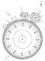
- Figure 1 schematically shows a filling machine, denoted as a whole with 1, for filling containers (here not shown, denoted with 2 in Figure 2 ), for example glass bottles, with a filling fluid, for example a carbonated pourable food product, such as beer (but it is again underlined that other type of containers and carbonated, or non-carbonated, liquids may as well be envisaged).
- a filling fluid for example a carbonated pourable food product, such as beer (but it is again underlined that other type of containers and carbonated, or non-carbonated, liquids may as well be envisaged).
- Filling machine 1 comprises a conveying device, including a rotating conveyor (or carousel) 4, which is mounted to rotate continuously (anticlockwise in Figure 1 ) about a substantially vertical longitudinal axis A.
- the rotating conveyor 4 receives a succession of empty containers from an input wheel 5, which is coupled thereto 4 at a first transfer station 6 and is mounted to rotate continuously about a respective vertical longitudinal axis B, parallel to axis A.
- the rotating conveyor 4 releases a succession of filled containers to an output wheel 8, which is coupled thereto at a second transfer station 9 and is mounted to rotate continuously about a respective vertical longitudinal axis C, parallel to axes A and B.
- Filling machine 1 comprises a number of filling units 10, which are equally spaced about axis A, are mounted along a peripheral edge of rotating conveyor 4, and are moved by the same rotating conveyor 4 along a path P extending about axis A and through transfer stations 6 and 9.
- Each filling unit 10 is designed to receive at least one container to be filled, and to perform, during its rotation along path P, filling operations according to a filling "recipe", in order to fill the container with a fluid (e.g. a carbonated liquid).
- Each filling unit 10 generally includes one or more fluidic conduits and flow regulators (here not shown), which are designed to selectively couple the container to one or more feed devices, or product tanks (also not shown), of the filling machine 1.
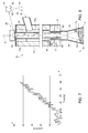
- each filling unit 10 includes a main body 12, for example with a tubular configuration, having a vertical extension along a longitudinal axis D that is substantially parallel to axis A of rotating conveyor 4.
- Main body 12 is mechanically coupled to the rotating conveyor 4 and includes, at a bottom portion thereof, a container receiving part, designed to releasably engage a neck 2' of the container 2 that is to be filled during filling operations thereof.
- filling unit 10 may also include gripping means, designed to hold the neck 2' of the container 2, to support it in a vertical position.
- main body 12 of filling unit 10 internally defines a hollow central conduit 14, and an annular conduit 15, extending around the central conduit 14, concentrically thereto, formed between an internal side wall of the main body 12 and an outer side wall of the same central conduit 14.
- Central conduit 14 extends around longitudinal axis D, for the whole vertical extension of the main body 12, is in fluid communication with the inside of the container 2 (through an opening at the neck 2' thereof), and is provided with an opening that is coupled to an air return passage 16 of filling unit 10 (only a portion of which is shown in Figure 2 , for sake of clarity).
- Air return passage 16 allows execution (via suitable valve arrangements, here not shown) of pressurization and/or air discharge operations related to the container 2 (in a known manner, here not discussed in detail); central conduit 14 thus operates as a venting conduit for the filling unit 10.
- air return passage 16 is located at the bottom part of main body 12, in the proximity of the neck 2' of the container 2.
- Annular conduit 15 also extends for the whole vertical extension of the main body 12, around central conduit 14, and it is coupled (via suitable valve arrangements, here not shown) to a product feed line 18, originated from a product tank (here not shown) coupled to the rotating conveyor 4 and containing the pourable liquid, here denoted with 19.
- Annular conduit 15 is also in fluid communication with the inside of the container 2 (through the neck 2' thereof) and allows filling of the same container 2 with the pourable liquid 19 (filling taking place starting from the side walls of the container 2, as schematically shown in Figure 2 ).
- filling units 10 of filling machine 1 further include a level sensing device 20, which is coupled to the main body 12, particularly to the central conduit 14 thereof, and is configured to provide sensing information related to the increasing filling level of liquid 19 within the related container 2.
- level sensing device 20 implements a laser sensor, configured to carry out a contactless sensing of the position of the surface 19a of the liquid 19 within the container 2 (in other words, of the distance between surface 19a and the sensing device 20), which is indicative of the filling level (denoted with L in Figure 2 ) within the same container 2.
- Surface 19a is the interface between the liquid 19 and the remaining air in the container 2.
- level sensing device 20 includes a casing 22, e.g. of a metallic material, in the embodiment housing a laser unit 23, including (in a respective package thereof) a laser emitter for example a semiconductor laser, such as a visible or infrared laser diode LD, generating a laser beam 24 (however, other types of laser units may as well be envisaged).
- a laser unit 23 including (in a respective package thereof) a laser emitter for example a semiconductor laser, such as a visible or infrared laser diode LD, generating a laser beam 24 (however, other types of laser units may as well be envisaged).
- Level sensing device 20 further includes a lens unit 25, in the embodiment arranged within the casing 22, in particular at a bottom portion thereof, so as to be interposed between the laser unit 23 and a laser outlet 22a from the same casing 22; lens unit 25 is optically and operatively coupled to the laser unit 23 and configured to focus and collimate the laser beam 24 towards the liquid 19 within the container 2. Lens unit 25 may be adjusted, e.g. in terms of its arrangement or parameters, in order to modify the properties of the generated laser beam 24, e.g. the focus and collimation parameters of the same laser beam 24.
- Level sensing device 20 moreover includes an electronic circuit 26, also arranged within the casing 22 and electrically and operatively coupled to the laser unit 23; and electrical connection elements 27, coupled to the electronic circuit 26 within the casing 22 and extending out of the same casing 22, so as to allow electrical connection to the outside (in particular to a power supply system and to an external computing unit or electronic device).
- casing 22 of level sensing device 20 is arranged at a top portion of the main body 12 of filling unit 10, opposite to the bottom part engaging the container 2 (with respect to the longitudinal axis D).
- the bottom portion of casing 22 is mechanically coupled to the main body 12, e.g. via a threaded coupling or other suitable coupling means, and laser outlet 22a faces the central conduit 14 defined in the same main body 12, so that laser beam 24 is directed within the same central conduit 14 (and into the container 2).
- laser unit 23 and lens unit 25 are arranged and configured in such a manner that laser beam 24 is directed (considering the axis of symmetry of the light beam) in a direction parallel to longitudinal axis D, substantially orthogonally to the surface 19a of liquid 19 within the container 2 (in a condition at rest, as it will be discussed in more details in the following).
- a possible embodiment of the level sensing device 20 is shown in more details in Figures 4a and 4b .
- casing 22 has a cylindrical configuration (during operation, extending along longitudinal axis D) and defines an internal space 29 where a circuit board (PCB) 30 is arranged; circuit board 30 integrates the electronic circuit 26 and is arranged vertically along the same longitudinal axis D.
- PCB circuit board
- Casing has an upper surface 22b, at which holes 32 are provided for passage of the electrical connection elements 27 (not shown in Figures 4a, 4b ), that are connected to the circuit board 30 within the internal space 29; and a lower surface 22c, where laser outlet 22a is provided.
- Laser unit 23 is coupled to the circuit board 30, facing the laser outlet 22a, so that the generated laser beam 24 is directed into a passage 35 defined by the internal space 29 towards the same laser outlet 22a.
- Lens unit 25 is also arranged in the same passage 35, interposed between the laser unit 23 and the laser outlet 22a.
- casing 22 is provided with a threaded part at the lower surface 22c, for coupling to the main body 12 of the filling unit 10.
- laser unit 23 is of the light feedback (or retro-injection or retroreflection) type, in particular a distributed feedback laser (DFB), and operates based on the self-mixing interferometry principle.
- DFB distributed feedback laser
- a fraction of laser beam 24 is reflected by the surface 19a of the liquid 19 in the container 2 back into the laser cavity of laser unit 23, mixing (in particular, self-mixing) with the light generated by the same laser unit 23 and giving rise to an interference pattern; in a known manner (here not discussed in detail), a modulation of the laser beam 24 is induced, in particular an amplitude modulation, whose characteristics (e.g. with respect to the number and frequency of interference fringes) are a function of the distance of the reflecting surface (and thus are indicative of the filling level of the liquid within the container 2).
- Laser unit 23 thus includes (in the package thereof) a photodetector, such as a photodiode, so as to monitor the effects due to the above modulation on the light pattern within the respective laser cavity.
- a photodetector such as a photodiode
- electronic circuit 26 includes: a driving stage 40, which is configured to drive the laser emitter of laser unit 23; an acquisition stage 41, e.g. including an FPGA (Field Programmable Gate Array), coupled to the same laser unit 23 (in particular to the associated photodetector), and configured to acquire electrical sensing signals related to the detected light pattern and to sample the same electrical sensing signals at a desired sampling frequency; a processing stage 42, e.g. including a microcontroller, coupled to the acquisition stage 41 and configured to process the sampled electrical sensing signals (e.g. via amplification and filtering operations); and an interface 43, e.g.
- a driving stage 40 which is configured to drive the laser emitter of laser unit 23
- an acquisition stage 41 e.g. including an FPGA (Field Programmable Gate Array)
- FPGA Field Programmable Gate Array
- processing stage 42 e.g. including a microcontroller
- the same microcontroller configured to interface with an output system, for example with an electronic control unit of the filling unit 10 (not shown, designed to control operation thereof in a known manner here not discussed in detail), to provide thereto, e.g. via a serial interface, the processed electrical signals, in order to allow further processing thereof, and/or a measure of the filling level inside the container 2 (it is clear, however, that part, or the whole of the processing operations on the sampled electrical signals may be performed within the same electronic circuit 26 of the level sensing device 20, or within an external circuitry).
- Processing operations have to cope with some issues related to the measuring environment, which may lead to errors and inaccuracies on the measured filling level.
- liquid 19 inside the container 2 is subject to movement, giving rise to a sloped surface 19a, ripples and waves, because of the centrifugal effects due to the rotation of the container 2 coupled to the rotating conveyor 4.
- sensor unit 23 relies on mirror-like reflection by the surface 19a of the liquid 19, it is clear that the above effects on the surface 19a may alter the measurement and even cause part or whole of the reflected beam to miss the laser cavity.
- processing operations may envisage:
- Figure 7 shows a possible result of the processing operations, depicting the filling level within the container 2, and in particular a first plot (shown with solid line) joining the sampled measured values and a second plot (sown with dashed line) representing the predicted and averaged value.
- the processed plot is an accurate representation of the pattern of the filling level within the container 2, thus showing the correct operation of sensing device 20.
- a further aspect of the present solution envisages a modification of the sensing device 20 and filling unit 10, in order to further improve the accuracy and reliability of the filling level measures.
- laser unit 23 is in this case configured so as to generate a first and a second light beams 24, 24', each one directed at a first angle ⁇ (having a non zero value, for example in the range 0-45°) with respect to the longitudinal axis D of the filling unit 10, thereby impinging upon a respective bottom portion 60, 60' of internal wall, here denoted with 14a, of central conduit 14; in the embodiment, light beams 24, 24', as well as bottom portions 60, 60', are symmetrical with respect to longitudinal axis D.
- first angle ⁇ having a non zero value, for example in the range 0-45°
- laser unit 23 may thus include a first and a second laser emitter arranged side by side, as schematically shown in the same Figure 8 (where the same emitters are denoted with 62, 62'), each one associated with a respective lens unit (here not shown, for sake of clarity).
- bottom portions 60, 60' of internal wall 14a are in this case coated with a reflective material (or a reflective layer is deposited on the same bottom portions 60, 60'); moreover, each bottom portion 60, 60' is inclined at a second angle ⁇ (having a non zero value, for example in the range 0-45°) with respect to longitudinal axis D.
- a suitable choice of the values of the first and second angles ⁇ , ⁇ allows to direct the laser beams 24, 24' within the container 2 so that they are directed towards (possibly substantially orthogonal to) the surface 19a of the liquid 19, which is inclined (with respect to a horizontal plane, e.g. parallel to the ground) due to the centrifugal effects acting on the same container 2.
- a first laser beam 24 impinges on the surface 19a of the liquid 19 at a first contact area, at a higher level L H
- a second laser beam 24' impinges on the surface 19a of the liquid 19 at a second contact area, at a lower level L L .
- Processing by the processing stage 42 may in this case envisage determining a mean value between the first, higher level L H , and the second, lower level L L , in order to determine the actual level L of fluid 19.
- a contactless measurement thus without affecting in any manner the liquid to be measured; a high level of accuracy (a feedback control may also be envisaged); less maintenance; easy replacement; less mechanical complexity; adjustable level set point (i.e. any desired filling level may be set for controlling the operation of the filling units 10).
- the possibility to adjust the properties of the laser beam 24 allows to finely tune the measurement to the characteristics of the particular system under investigation; for example, tests made by the Applicant have shown that, in certain operating conditions, focusing the laser beam 24 on the bottom of the container 2 may help improving the quality and reliability of the filling level measures.
- the present solution has been discussed with specific reference to glass bottles, it can of course be used also in case of PET bottles, which however may be subject to deformation during transportation and filling.
- Another advantageous possibility is in this case using the level sensing device 20 also to detect level changes due to PET bottle deformation, and the possibility to compensate for those deformations to ensure a correct level of liquid in the finally filled and capped bottles.
- filling units 10 may instead move towards the respective containers, fixed to a respective support.
- the arrangement of the sensing device 20 with respect to the filling unit 10 may differ with respect to what previously discussed and shown in detail, provided that the laser unit 23 is arranged so that the laser beam 24 reaches the inside of the container 2.
- the sensing device 20 may be arranged within the main body 12 of the filling unit 10, along the longitudinal axis D; in this case, laser unit 23 may be sized so as to be arranged, externally to the casing 22 of sensing device 20, within the central conduit 14, at a desired height along the longitudinal axis D (in any case above the point at which the air return passage 16 is coupled to the same central conduit 14, so as not to create obstacles to the passage of air).
- 0-rings and/or suitable fixing elements may be employed to keep the laser unit 23 (and associated lens unit 25) in place and in a vertical position during measurement.
- Electrical connecting means 70 are in this case provided to connect the laser unit 22 to the electronic circuit 26 of sensing device 20.
- the sensing device 20 may also be configured to be easily inserted (as a retro-fit option) to existing filling units 10.
Priority Applications (1)
| Application Number | Priority Date | Filing Date | Title |
|---|---|---|---|
| EP14167450.7A EP2942322B1 (fr) | 2014-05-07 | 2014-05-07 | Machine de remplissage de récipient avec une meilleure détection d'un niveau de remplissage et procédé associé |
Applications Claiming Priority (1)
| Application Number | Priority Date | Filing Date | Title |
|---|---|---|---|
| EP14167450.7A EP2942322B1 (fr) | 2014-05-07 | 2014-05-07 | Machine de remplissage de récipient avec une meilleure détection d'un niveau de remplissage et procédé associé |
Publications (2)
| Publication Number | Publication Date |
|---|---|
| EP2942322A1 true EP2942322A1 (fr) | 2015-11-11 |
| EP2942322B1 EP2942322B1 (fr) | 2016-09-14 |
Family
ID=50630717
Family Applications (1)
| Application Number | Title | Priority Date | Filing Date |
|---|---|---|---|
| EP14167450.7A Not-in-force EP2942322B1 (fr) | 2014-05-07 | 2014-05-07 | Machine de remplissage de récipient avec une meilleure détection d'un niveau de remplissage et procédé associé |
Country Status (1)
| Country | Link |
|---|---|
| EP (1) | EP2942322B1 (fr) |
Cited By (4)
| Publication number | Priority date | Publication date | Assignee | Title |
|---|---|---|---|---|
| WO2018108575A1 (fr) * | 2016-12-15 | 2018-06-21 | Khs Gmbh | Machine de remplissage et procédé permettant de remplir des récipients |
| WO2020083654A1 (fr) * | 2018-10-23 | 2020-04-30 | Khs Gmbh | Système de remplissage pour le remplissage de récipients avec un produit de remplissage liquide et machine de remplissage |
| EP3646035A4 (fr) * | 2017-06-26 | 2020-08-19 | Luedemann, Hans-Christian | Dispositif de transfert de liquide à capteur intégré de distance et de hauteur de remplissage de liquide sans contact, et procédés |
| EP3733588A1 (fr) * | 2019-04-25 | 2020-11-04 | Krones Ag | Dispositif et procédé d'expansion d'un produit de remplissage rempli dans un récipient |
Citations (6)
| Publication number | Priority date | Publication date | Assignee | Title |
|---|---|---|---|---|
| US4015645A (en) * | 1973-10-01 | 1977-04-05 | Fmc Corporation | Can filling apparatus |
| EP0237823A1 (fr) * | 1986-02-22 | 1987-09-23 | Seitz Enzinger Noll Maschinenbau Aktiengesellschaft | Elément de remplissage sans tube de remplissage pour des machines de remplissage |
| DE3909405A1 (de) * | 1988-05-10 | 1989-11-16 | Seitz Enzinger Noll Masch | Fuellelement |
| EP1562027A1 (fr) * | 2004-02-06 | 2005-08-10 | Hitachi High-Technologies Corporation | Dispositif de distribution de liquide, analyseur automatique utilisant un tel dispositif et dispositif pour la détection d'une surface de liquide |
| US20070107801A1 (en) * | 2005-11-14 | 2007-05-17 | Sidel And Pressco Technology Inc. | Bottle filling machine with sensor and method thereof |
| EP2192076A1 (fr) * | 2008-12-01 | 2010-06-02 | Newtec Filling Systems | Dispositif de remplissage d'une bouteille et système automatique de remplissage de bouteilles correspondant |
-
2014
- 2014-05-07 EP EP14167450.7A patent/EP2942322B1/fr not_active Not-in-force
Patent Citations (6)
| Publication number | Priority date | Publication date | Assignee | Title |
|---|---|---|---|---|
| US4015645A (en) * | 1973-10-01 | 1977-04-05 | Fmc Corporation | Can filling apparatus |
| EP0237823A1 (fr) * | 1986-02-22 | 1987-09-23 | Seitz Enzinger Noll Maschinenbau Aktiengesellschaft | Elément de remplissage sans tube de remplissage pour des machines de remplissage |
| DE3909405A1 (de) * | 1988-05-10 | 1989-11-16 | Seitz Enzinger Noll Masch | Fuellelement |
| EP1562027A1 (fr) * | 2004-02-06 | 2005-08-10 | Hitachi High-Technologies Corporation | Dispositif de distribution de liquide, analyseur automatique utilisant un tel dispositif et dispositif pour la détection d'une surface de liquide |
| US20070107801A1 (en) * | 2005-11-14 | 2007-05-17 | Sidel And Pressco Technology Inc. | Bottle filling machine with sensor and method thereof |
| EP2192076A1 (fr) * | 2008-12-01 | 2010-06-02 | Newtec Filling Systems | Dispositif de remplissage d'une bouteille et système automatique de remplissage de bouteilles correspondant |
Cited By (6)
| Publication number | Priority date | Publication date | Assignee | Title |
|---|---|---|---|---|
| WO2018108575A1 (fr) * | 2016-12-15 | 2018-06-21 | Khs Gmbh | Machine de remplissage et procédé permettant de remplir des récipients |
| EP3646035A4 (fr) * | 2017-06-26 | 2020-08-19 | Luedemann, Hans-Christian | Dispositif de transfert de liquide à capteur intégré de distance et de hauteur de remplissage de liquide sans contact, et procédés |
| WO2020083654A1 (fr) * | 2018-10-23 | 2020-04-30 | Khs Gmbh | Système de remplissage pour le remplissage de récipients avec un produit de remplissage liquide et machine de remplissage |
| CN112912334A (zh) * | 2018-10-23 | 2021-06-04 | Khs有限责任公司 | 用于给容器灌装液态填料的灌装系统以及灌装机 |
| US11407628B2 (en) | 2018-10-23 | 2022-08-09 | Khs Gmbh | Filling system for filling containers with a fluid filling material and filling machine |
| EP3733588A1 (fr) * | 2019-04-25 | 2020-11-04 | Krones Ag | Dispositif et procédé d'expansion d'un produit de remplissage rempli dans un récipient |
Also Published As
| Publication number | Publication date |
|---|---|
| EP2942322B1 (fr) | 2016-09-14 |
Similar Documents
| Publication | Publication Date | Title |
|---|---|---|
| EP2942322B1 (fr) | Machine de remplissage de récipient avec une meilleure détection d'un niveau de remplissage et procédé associé | |
| US11340106B2 (en) | Fill-level measuring device | |
| US10829362B2 (en) | Foam and liquid fill level detection system | |
| CA2269750C (fr) | Balayage d'absorbance incrementale d'un liquide dans des embouts de distribution | |
| US20170129759A1 (en) | Container filling machine with weighing device and weighing method | |
| EP3482170B1 (fr) | Système d'automatisation de laboratoire et procédé permettant de pipetter un échantillon de laboratoire | |
| US7916299B2 (en) | Method and apparatus for optical detection of a phase transition | |
| EP0972174A1 (fr) | Systeme optique de detection du niveau de remplissage et procedes associes | |
| CA2842608A1 (fr) | Appareil servant a determiner une position verticale d'au moins une interface entre une premiere composante et au moins une deuxieme composante et systeme d'automatisation de laboratoire | |
| US20160282106A1 (en) | Method and device for establishing a geometry of a container for packaging a flowable medium | |
| US11237179B2 (en) | Calibration curve generating method and automatic analyzing apparatus | |
| ITMI20120108A1 (it) | Gruppo di misura in linea della quantita' di anidride carbonica disciolta in un liquido contenuto in un contenitore chiuso e linea di riempimento automatico di contenitori comprendente lo stesso | |
| TWI413769B (zh) | 偵測流體的系統 | |
| RU56599U1 (ru) | Уровнемер жидкости | |
| WO2013061645A1 (fr) | Dispositif d'inspection de la pression interne d'un récipient fermé hermétiquement et procédé d'inspection de la pression interne | |
| US20150160252A1 (en) | Method and apparatus for detecting position of liquid surface, liquid supply apparatus, and analyzing system | |
| KR101847212B1 (ko) | 시료액 계량장치 | |
| US6049585A (en) | Non-destructive x-ray inspection apparatus for liquid foodstuffs contained in glass vessels or bottles | |
| WO2020195500A1 (fr) | Appareil d'analyse automatique | |
| RU2689288C2 (ru) | Устройство размерного контроля сосудов путем бесконтактного оптического обнаружения | |
| JP2010133824A (ja) | キャップ検査装置及びキャップ検査方法 | |
| US11579006B2 (en) | Radar level gauge and method for detecting a cleaning process using the radar level gauge | |
| CN211593104U (zh) | 包装瓶热塑膜的检测装置 | |
| CN109031450B (zh) | 一种食品加工检测系统 | |
| CN217074880U (zh) | 一种疫苗瓶灌装量检测系统 |
Legal Events
| Date | Code | Title | Description |
|---|---|---|---|
| PUAI | Public reference made under article 153(3) epc to a published international application that has entered the european phase |
Free format text: ORIGINAL CODE: 0009012 |
|
| AK | Designated contracting states |
Kind code of ref document: A1 Designated state(s): AL AT BE BG CH CY CZ DE DK EE ES FI FR GB GR HR HU IE IS IT LI LT LU LV MC MK MT NL NO PL PT RO RS SE SI SK SM TR |
|
| AX | Request for extension of the european patent |
Extension state: BA ME |
|
| 17P | Request for examination filed |
Effective date: 20151229 |
|
| RBV | Designated contracting states (corrected) |
Designated state(s): AL AT BE BG CH CY CZ DE DK EE ES FI FR GB GR HR HU IE IS IT LI LT LU LV MC MK MT NL NO PL PT RO RS SE SI SK SM TR |
|
| GRAP | Despatch of communication of intention to grant a patent |
Free format text: ORIGINAL CODE: EPIDOSNIGR1 |
|
| RIC1 | Information provided on ipc code assigned before grant |
Ipc: B67C 3/28 20060101AFI20160222BHEP Ipc: G01F 23/292 20060101ALI20160222BHEP |
|
| INTG | Intention to grant announced |
Effective date: 20160324 |
|
| RAP1 | Party data changed (applicant data changed or rights of an application transferred) |
Owner name: SIDEL S.P.A. CON SOCIO UNICO |
|
| GRAS | Grant fee paid |
Free format text: ORIGINAL CODE: EPIDOSNIGR3 |
|
| GRAA | (expected) grant |
Free format text: ORIGINAL CODE: 0009210 |
|
| AK | Designated contracting states |
Kind code of ref document: B1 Designated state(s): AL AT BE BG CH CY CZ DE DK EE ES FI FR GB GR HR HU IE IS IT LI LT LU LV MC MK MT NL NO PL PT RO RS SE SI SK SM TR |
|
| REG | Reference to a national code |
Ref country code: GB Ref legal event code: FG4D |
|
| REG | Reference to a national code |
Ref country code: CH Ref legal event code: EP |
|
| REG | Reference to a national code |
Ref country code: IE Ref legal event code: FG4D |
|
| REG | Reference to a national code |
Ref country code: AT Ref legal event code: REF Ref document number: 828746 Country of ref document: AT Kind code of ref document: T Effective date: 20161015 |
|
| REG | Reference to a national code |
Ref country code: DE Ref legal event code: R096 Ref document number: 602014003577 Country of ref document: DE |
|
| REG | Reference to a national code |
Ref country code: LT Ref legal event code: MG4D |
|
| REG | Reference to a national code |
Ref country code: NL Ref legal event code: MP Effective date: 20160914 |
|
| PG25 | Lapsed in a contracting state [announced via postgrant information from national office to epo] |
Ref country code: RS Free format text: LAPSE BECAUSE OF FAILURE TO SUBMIT A TRANSLATION OF THE DESCRIPTION OR TO PAY THE FEE WITHIN THE PRESCRIBED TIME-LIMIT Effective date: 20160914 Ref country code: NO Free format text: LAPSE BECAUSE OF FAILURE TO SUBMIT A TRANSLATION OF THE DESCRIPTION OR TO PAY THE FEE WITHIN THE PRESCRIBED TIME-LIMIT Effective date: 20161214 Ref country code: FI Free format text: LAPSE BECAUSE OF FAILURE TO SUBMIT A TRANSLATION OF THE DESCRIPTION OR TO PAY THE FEE WITHIN THE PRESCRIBED TIME-LIMIT Effective date: 20160914 Ref country code: LT Free format text: LAPSE BECAUSE OF FAILURE TO SUBMIT A TRANSLATION OF THE DESCRIPTION OR TO PAY THE FEE WITHIN THE PRESCRIBED TIME-LIMIT Effective date: 20160914 Ref country code: HR Free format text: LAPSE BECAUSE OF FAILURE TO SUBMIT A TRANSLATION OF THE DESCRIPTION OR TO PAY THE FEE WITHIN THE PRESCRIBED TIME-LIMIT Effective date: 20160914 |
|
| REG | Reference to a national code |
Ref country code: AT Ref legal event code: MK05 Ref document number: 828746 Country of ref document: AT Kind code of ref document: T Effective date: 20160914 |
|
| PG25 | Lapsed in a contracting state [announced via postgrant information from national office to epo] |
Ref country code: GR Free format text: LAPSE BECAUSE OF FAILURE TO SUBMIT A TRANSLATION OF THE DESCRIPTION OR TO PAY THE FEE WITHIN THE PRESCRIBED TIME-LIMIT Effective date: 20161215 Ref country code: NL Free format text: LAPSE BECAUSE OF FAILURE TO SUBMIT A TRANSLATION OF THE DESCRIPTION OR TO PAY THE FEE WITHIN THE PRESCRIBED TIME-LIMIT Effective date: 20160914 Ref country code: SE Free format text: LAPSE BECAUSE OF FAILURE TO SUBMIT A TRANSLATION OF THE DESCRIPTION OR TO PAY THE FEE WITHIN THE PRESCRIBED TIME-LIMIT Effective date: 20160914 Ref country code: LV Free format text: LAPSE BECAUSE OF FAILURE TO SUBMIT A TRANSLATION OF THE DESCRIPTION OR TO PAY THE FEE WITHIN THE PRESCRIBED TIME-LIMIT Effective date: 20160914 |
|
| PG25 | Lapsed in a contracting state [announced via postgrant information from national office to epo] |
Ref country code: RO Free format text: LAPSE BECAUSE OF FAILURE TO SUBMIT A TRANSLATION OF THE DESCRIPTION OR TO PAY THE FEE WITHIN THE PRESCRIBED TIME-LIMIT Effective date: 20160914 Ref country code: EE Free format text: LAPSE BECAUSE OF FAILURE TO SUBMIT A TRANSLATION OF THE DESCRIPTION OR TO PAY THE FEE WITHIN THE PRESCRIBED TIME-LIMIT Effective date: 20160914 |
|
| PG25 | Lapsed in a contracting state [announced via postgrant information from national office to epo] |
Ref country code: SK Free format text: LAPSE BECAUSE OF FAILURE TO SUBMIT A TRANSLATION OF THE DESCRIPTION OR TO PAY THE FEE WITHIN THE PRESCRIBED TIME-LIMIT Effective date: 20160914 Ref country code: PT Free format text: LAPSE BECAUSE OF FAILURE TO SUBMIT A TRANSLATION OF THE DESCRIPTION OR TO PAY THE FEE WITHIN THE PRESCRIBED TIME-LIMIT Effective date: 20170116 Ref country code: AT Free format text: LAPSE BECAUSE OF FAILURE TO SUBMIT A TRANSLATION OF THE DESCRIPTION OR TO PAY THE FEE WITHIN THE PRESCRIBED TIME-LIMIT Effective date: 20160914 Ref country code: ES Free format text: LAPSE BECAUSE OF FAILURE TO SUBMIT A TRANSLATION OF THE DESCRIPTION OR TO PAY THE FEE WITHIN THE PRESCRIBED TIME-LIMIT Effective date: 20160914 Ref country code: BE Free format text: LAPSE BECAUSE OF FAILURE TO SUBMIT A TRANSLATION OF THE DESCRIPTION OR TO PAY THE FEE WITHIN THE PRESCRIBED TIME-LIMIT Effective date: 20160914 Ref country code: CZ Free format text: LAPSE BECAUSE OF FAILURE TO SUBMIT A TRANSLATION OF THE DESCRIPTION OR TO PAY THE FEE WITHIN THE PRESCRIBED TIME-LIMIT Effective date: 20160914 Ref country code: SM Free format text: LAPSE BECAUSE OF FAILURE TO SUBMIT A TRANSLATION OF THE DESCRIPTION OR TO PAY THE FEE WITHIN THE PRESCRIBED TIME-LIMIT Effective date: 20160914 Ref country code: IS Free format text: LAPSE BECAUSE OF FAILURE TO SUBMIT A TRANSLATION OF THE DESCRIPTION OR TO PAY THE FEE WITHIN THE PRESCRIBED TIME-LIMIT Effective date: 20170114 Ref country code: PL Free format text: LAPSE BECAUSE OF FAILURE TO SUBMIT A TRANSLATION OF THE DESCRIPTION OR TO PAY THE FEE WITHIN THE PRESCRIBED TIME-LIMIT Effective date: 20160914 Ref country code: BG Free format text: LAPSE BECAUSE OF FAILURE TO SUBMIT A TRANSLATION OF THE DESCRIPTION OR TO PAY THE FEE WITHIN THE PRESCRIBED TIME-LIMIT Effective date: 20161214 |
|
| REG | Reference to a national code |
Ref country code: DE Ref legal event code: R097 Ref document number: 602014003577 Country of ref document: DE |
|
| PLBE | No opposition filed within time limit |
Free format text: ORIGINAL CODE: 0009261 |
|
| STAA | Information on the status of an ep patent application or granted ep patent |
Free format text: STATUS: NO OPPOSITION FILED WITHIN TIME LIMIT |
|
| PG25 | Lapsed in a contracting state [announced via postgrant information from national office to epo] |
Ref country code: DK Free format text: LAPSE BECAUSE OF FAILURE TO SUBMIT A TRANSLATION OF THE DESCRIPTION OR TO PAY THE FEE WITHIN THE PRESCRIBED TIME-LIMIT Effective date: 20160914 |
|
| 26N | No opposition filed |
Effective date: 20170615 |
|
| PG25 | Lapsed in a contracting state [announced via postgrant information from national office to epo] |
Ref country code: LU Free format text: LAPSE BECAUSE OF NON-PAYMENT OF DUE FEES Effective date: 20170531 |
|
| PGFP | Annual fee paid to national office [announced via postgrant information from national office to epo] |
Ref country code: IT Payment date: 20170531 Year of fee payment: 4 |
|
| PG25 | Lapsed in a contracting state [announced via postgrant information from national office to epo] |
Ref country code: SI Free format text: LAPSE BECAUSE OF FAILURE TO SUBMIT A TRANSLATION OF THE DESCRIPTION OR TO PAY THE FEE WITHIN THE PRESCRIBED TIME-LIMIT Effective date: 20160914 |
|
| REG | Reference to a national code |
Ref country code: DE Ref legal event code: R119 Ref document number: 602014003577 Country of ref document: DE |
|
| REG | Reference to a national code |
Ref country code: CH Ref legal event code: PL |
|
| PG25 | Lapsed in a contracting state [announced via postgrant information from national office to epo] |
Ref country code: MC Free format text: LAPSE BECAUSE OF FAILURE TO SUBMIT A TRANSLATION OF THE DESCRIPTION OR TO PAY THE FEE WITHIN THE PRESCRIBED TIME-LIMIT Effective date: 20160914 |
|
| REG | Reference to a national code |
Ref country code: IE Ref legal event code: MM4A |
|
| PG25 | Lapsed in a contracting state [announced via postgrant information from national office to epo] |
Ref country code: LI Free format text: LAPSE BECAUSE OF NON-PAYMENT OF DUE FEES Effective date: 20170531 Ref country code: CH Free format text: LAPSE BECAUSE OF NON-PAYMENT OF DUE FEES Effective date: 20170531 |
|
| REG | Reference to a national code |
Ref country code: FR Ref legal event code: ST Effective date: 20180131 |
|
| PG25 | Lapsed in a contracting state [announced via postgrant information from national office to epo] |
Ref country code: LU Free format text: LAPSE BECAUSE OF NON-PAYMENT OF DUE FEES Effective date: 20170507 |
|
| PG25 | Lapsed in a contracting state [announced via postgrant information from national office to epo] |
Ref country code: IE Free format text: LAPSE BECAUSE OF NON-PAYMENT OF DUE FEES Effective date: 20170507 Ref country code: DE Free format text: LAPSE BECAUSE OF NON-PAYMENT OF DUE FEES Effective date: 20171201 |
|
| PG25 | Lapsed in a contracting state [announced via postgrant information from national office to epo] |
Ref country code: FR Free format text: LAPSE BECAUSE OF NON-PAYMENT OF DUE FEES Effective date: 20170531 |
|
| PG25 | Lapsed in a contracting state [announced via postgrant information from national office to epo] |
Ref country code: MT Free format text: LAPSE BECAUSE OF NON-PAYMENT OF DUE FEES Effective date: 20170507 |
|
| PG25 | Lapsed in a contracting state [announced via postgrant information from national office to epo] |
Ref country code: AL Free format text: LAPSE BECAUSE OF FAILURE TO SUBMIT A TRANSLATION OF THE DESCRIPTION OR TO PAY THE FEE WITHIN THE PRESCRIBED TIME-LIMIT Effective date: 20160914 |
|
| GBPC | Gb: european patent ceased through non-payment of renewal fee |
Effective date: 20180507 |
|
| PG25 | Lapsed in a contracting state [announced via postgrant information from national office to epo] |
Ref country code: IT Free format text: LAPSE BECAUSE OF NON-PAYMENT OF DUE FEES Effective date: 20180507 Ref country code: GB Free format text: LAPSE BECAUSE OF NON-PAYMENT OF DUE FEES Effective date: 20180507 |
|
| PG25 | Lapsed in a contracting state [announced via postgrant information from national office to epo] |
Ref country code: HU Free format text: LAPSE BECAUSE OF FAILURE TO SUBMIT A TRANSLATION OF THE DESCRIPTION OR TO PAY THE FEE WITHIN THE PRESCRIBED TIME-LIMIT; INVALID AB INITIO Effective date: 20140507 |
|
| PG25 | Lapsed in a contracting state [announced via postgrant information from national office to epo] |
Ref country code: CY Free format text: LAPSE BECAUSE OF FAILURE TO SUBMIT A TRANSLATION OF THE DESCRIPTION OR TO PAY THE FEE WITHIN THE PRESCRIBED TIME-LIMIT Effective date: 20160914 |
|
| PG25 | Lapsed in a contracting state [announced via postgrant information from national office to epo] |
Ref country code: MK Free format text: LAPSE BECAUSE OF FAILURE TO SUBMIT A TRANSLATION OF THE DESCRIPTION OR TO PAY THE FEE WITHIN THE PRESCRIBED TIME-LIMIT Effective date: 20160914 |
|
| PG25 | Lapsed in a contracting state [announced via postgrant information from national office to epo] |
Ref country code: TR Free format text: LAPSE BECAUSE OF FAILURE TO SUBMIT A TRANSLATION OF THE DESCRIPTION OR TO PAY THE FEE WITHIN THE PRESCRIBED TIME-LIMIT Effective date: 20160914 |