EP2942014B1 - Craniostat zur erfassung extraoraler dentaler röntgenaufnahmen - Google Patents
Craniostat zur erfassung extraoraler dentaler röntgenaufnahmen Download PDFInfo
- Publication number
- EP2942014B1 EP2942014B1 EP15163924.2A EP15163924A EP2942014B1 EP 2942014 B1 EP2942014 B1 EP 2942014B1 EP 15163924 A EP15163924 A EP 15163924A EP 2942014 B1 EP2942014 B1 EP 2942014B1
- Authority
- EP
- European Patent Office
- Prior art keywords
- craniostat
- bite
- patient
- base
- lever
- Prior art date
- Legal status (The legal status is an assumption and is not a legal conclusion. Google has not performed a legal analysis and makes no representation as to the accuracy of the status listed.)
- Active
Links
Images


Classifications
-
- A—HUMAN NECESSITIES
- A61—MEDICAL OR VETERINARY SCIENCE; HYGIENE
- A61B—DIAGNOSIS; SURGERY; IDENTIFICATION
- A61B6/00—Apparatus or devices for radiation diagnosis; Apparatus or devices for radiation diagnosis combined with radiation therapy equipment
- A61B6/50—Apparatus or devices for radiation diagnosis; Apparatus or devices for radiation diagnosis combined with radiation therapy equipment specially adapted for specific body parts; specially adapted for specific clinical applications
- A61B6/51—Apparatus or devices for radiation diagnosis; Apparatus or devices for radiation diagnosis combined with radiation therapy equipment specially adapted for specific body parts; specially adapted for specific clinical applications for dentistry
-
- A—HUMAN NECESSITIES
- A61—MEDICAL OR VETERINARY SCIENCE; HYGIENE
- A61B—DIAGNOSIS; SURGERY; IDENTIFICATION
- A61B6/00—Apparatus or devices for radiation diagnosis; Apparatus or devices for radiation diagnosis combined with radiation therapy equipment
- A61B6/04—Positioning of patients; Tiltable beds or the like
-
- A—HUMAN NECESSITIES
- A61—MEDICAL OR VETERINARY SCIENCE; HYGIENE
- A61B—DIAGNOSIS; SURGERY; IDENTIFICATION
- A61B6/00—Apparatus or devices for radiation diagnosis; Apparatus or devices for radiation diagnosis combined with radiation therapy equipment
- A61B6/50—Apparatus or devices for radiation diagnosis; Apparatus or devices for radiation diagnosis combined with radiation therapy equipment specially adapted for specific body parts; specially adapted for specific clinical applications
- A61B6/501—Apparatus or devices for radiation diagnosis; Apparatus or devices for radiation diagnosis combined with radiation therapy equipment specially adapted for specific body parts; specially adapted for specific clinical applications for diagnosis of the head, e.g. neuroimaging or craniography
-
- F—MECHANICAL ENGINEERING; LIGHTING; HEATING; WEAPONS; BLASTING
- F16—ENGINEERING ELEMENTS AND UNITS; GENERAL MEASURES FOR PRODUCING AND MAINTAINING EFFECTIVE FUNCTIONING OF MACHINES OR INSTALLATIONS; THERMAL INSULATION IN GENERAL
- F16B—DEVICES FOR FASTENING OR SECURING CONSTRUCTIONAL ELEMENTS OR MACHINE PARTS TOGETHER, e.g. NAILS, BOLTS, CIRCLIPS, CLAMPS, CLIPS OR WEDGES; JOINTS OR JOINTING
- F16B2/00—Friction-grip releasable fastenings
- F16B2/02—Clamps, i.e. with gripping action effected by positive means other than the inherent resistance to deformation of the material of the fastening
- F16B2/18—Clamps, i.e. with gripping action effected by positive means other than the inherent resistance to deformation of the material of the fastening using cams, levers, eccentrics, or toggles
Definitions
- the present invention relates to extraoral dental digital radiographic apparatuses, wherein both the X-ray source and the X-ray sensor are placed outside patient's oral cavity.
- the present invention relates to a device for immobilizing patient's head during radiographic acquisitions, i.e. a craniostat according to the preamble of claim 1.
- Extraoral dental radiographic apparatuses can produce two kinds of radiographies: bi-dimensional (2D) radiographies, or volumetric (3D) radiographies.
- panoramic radiographies In the field of bi-dimensional radiographies, panoramic radiographies and teleradiographies are included.
- Panoramic radiography also known as orthopantomography produces a radiographic image of a curved plan, known as Welander's curve, approximating patient jaws, with blurring of the anatomical structures laying outside a narrow layer around the predesigned curved plane. This technology has been known since the '50s.
- Teleradiography is a projective radiographic technique, producing radiographic images of the skull or of other anatomical areas from different projections, with minimum magnification and geometrical distortion. Usually two perspectives are represented, latero-lateral and anteroposterior.
- Cone beam volumetric radiography also known as CBCT is the acquisition, from different projection angles, of a series of bi-dimensional radiographic images which will be processed post-acquisition to reconstruct three-dimensional volumes.
- Extraoral radiographies are performed through known apparatuses, wherein typically at the two ends of a C-arm an X-ray source and an X-ray sensor are positioned, respectively, while a patient is placed between them.
- the X-ray source and sensor rotate around patient's head, which is kept still by a positioning device (craniostat).
- the movements that mechanical parts have to perform in order to get this result is called trajectory.
- the patient In order to get a good image, the patient must remain still during the acquisition time, that is during X-ray emission. On the other hand, it is easy to realize that the patient will stand still if she/he is comfortable, while if she/he is uncomfortable, or under stress, there are more probabilities for her/him to move.
- the craniostat should be as transparent as possible to X-rays, in order not to create artefacts which might reduce the diagnostic validity of the radiographic image. This has an impact on materials (no metallic materials can be used), but also on thicknesses, in that with increasing thickness even a radiolucent material begins to appear in radiographies. However, the reduction of thickness bears the risk of making the craniostat not rigid enough to ensure the solidity of the object and therefore patient's immobility.
- the contact parts of the craniostat must be disposable, or must be disinfectable between patients.
- the craniostat must allow the positioning of any patient: from paediatric patients to adult patients of big dimensions (99 percentile), and therefore must fit cranial measures presenting a wide variability (cranium diameter going from 14 cm to 18.5 cm).
- the extraoral dental radiographic apparatus In order to perform all the kinds of acquisitions which will be described in the following, the extraoral dental radiographic apparatus must be able to perform an ample number of different trajectories, and therefore the C-arm needs wide possibilities of movement around the patient.
- Trajectories have a generically circular or semi-circular shape, and it is therefore possible to define an "anti-collision cylinder" wherein neither X-ray source nor X-ray sensor can enter. Once defined an as small as possible anti-collision cylinder, both patient's head and craniostat must be contained inside it. It is therefore important that the craniostat is not bulky, so as to not constitute a limit for the trajectories.
- the craniostat In order to perform all the kinds of acquisition, especially teleradiographies, the craniostat has to be removed by X-ray path during the acquisition.
- the craniostat must allow a rapid and easy positioning of the patient by the professional human operator.
- Frankfurt plane which is a virtual plane passing through the inferior margin of the left orbit and the upper margin of each ear canal or external auditory meatus, immediately under the eye.
- Document US3936641 shows a positioning device for the head of a patient, in an apparatus for carrying out x-ray imaging, and may be considered to disclose the preamble of claim 1.
- Document WO2013014488 discloses a craniostat in which no bite centrinbg and blocking mechanism is provided.
- Aim of the present invention is providing a craniostat according to the above-quoted requirements, and which is of easy and economic manufacturing.
- the craniostat of the present invention is an integral object removably mounted on a specific support.
- the craniostat can be removed from said support, the removal being necessary during apparatus calibration and when teleradiographies are performed, as the craniostat is on the X-ray path (during teleradiographies the patient is blocked by another specific positioning device).
- the removing system must be simple and ergonomic for the operator, without undermining the necessary stability of the craniostat while it is in use.
- the coupling craniostat-support is realized with four pins which enter into four specific pin holes, one of which is longer than the others.
- craniostat can be subdivided into two portions:
- the lower portion of the craniostat comprises a supporting base for fixed or removable parts supporting different anatomic portions of the patient: rods supporting the upper portion of the craniostat, bite for the patient, chin support and other supports for different kinds of acquisitions.
- the lower base exhibits a recess towards the patient which is useful to acquire temporomandibular radiographies with both open and closed mouth.
- the lower base brings a bite having a height adjustable with respect to the base itself, correspondently to the needs of the specific acquisition needs and of patient's anatomy.
- the bite is height adjustable, and must be blocked at different heights.
- the bite can be continuously blocked at any height comprised between a minimum and a maximum (no pre-defined heights are present); for the bite-wing position only a pre-defined height is required.
- a small lever loaded by a spring indicates to the operator that the correct height was reached, without the need of indications on bite stem, like notches or coloured points of reference, which must be optically checked by the operator.
- the shape of the bite must be such at to ensure the smallest radiopacity; for this an arch shape was chosen, instead of a L-shape.
- the bite is used with a disposable cover for patient's hygiene, which is changed between patients; the bite is made of only one material, and is optionally autoclavable.
- the thickness of the material is as low as possible to ensure radiolucency, so as not to visualize the bite in the radiographic image.
- bite height is free; once the desired height was reached, the bite is blocked in the correct position through a lever positioned in the anterior part of the base.
- the bite until it is blocked, freely rotates in its seat, and this facilitates patient's positioning; however, when the bite is blocked in its correct height through its lever, is also automatically centred, so as to ensure that the patient is correctly positioned on the sagittal plane.
- the bite is blocked in the desired position through a lever, which, in addition to blocking the bite in the vertical direction, sagittally rotates the bite itself bringing it in a position symmetrical to the sagittal plane.
- the distance between the bite point and the rods is the shortest possible to allow the passage of the sensor without collision, but at the same time ensuring that rods are outside the acquisition plane, therefore in the blurred area.
- the chin support is also removable, to allow the maximal versatility of use of the craniostat (open mouth acquisition of temporomandibular joints).
- the coupling occurs through two pins, having the same length.
- the craniostat can be made of plastic materials, so ensuring radiolucency and preventing scattering artefacts due to metal.
- the plurality of supporting points for patient's head makes the positioning comfortable for the patient, and nonetheless very stable.
- the difference in diameter between a very big patient and the anti-collision cylinder is very limited, about 2-3 cm. Therefore, the limited thickness of the craniostat allows both to perform complex trajectories, and to obtain the maximal radiolucency of the craniostat in radiographies.
- the craniostat of the present invention a positioning philosophy was chosen that is different from the system making use of an electromagnet or pre-loaded springs.
- the craniostat holding capability is in the first case dependent on how much the operator tightens the adjusting mechanisms, in the second case on how much the spring is pre-loaded. Therefore, such objects are very stable but also very rigid, and not very comfortable for the patient.
- the adjusting systems work so that first the operator approaches the contact points to the patient, and then blocks the contact point in that position, allowing an adjustment that is much more respectful of patient's anatomy and comfort. The operator gets a tactile and/or acoustic feed-back for each adjustment.
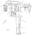
- Figure 1 shows a typical extraoral radiographic apparatus 1 of the known art, comprising an X-ray source 7 projecting a collimated bundle of X-rays through a (not shown) patient; a bi-dimensional X-ray sensor 8 positioned so as to measure the intensity of X-rays after they crossed the patient; a device 5 for the positioning of the patient interposed between X-ray source and sensor; a C-arm 6 on whose ends said X-ray source 7 and sensor 8 are supported; a mechanical system allowing the rotation and the translation of said C-arm around the patient, in order to acquire radiographic images from various positions; (not shown) electronic circuits such as to adjust and synchronize the working of the various parts of the apparatus.
- the position of the C-arm 6 can be adjusted to patient's height thanks to column 4 sliding on columns 3 fixed to the ground through base 2.
- the extraoral apparatus 1 may further comprise an arm 11 for teleradiography, to which a further patient's positioning device 13 is fixed, and a teleradiography sensor 15 is removably fixed on support 12.
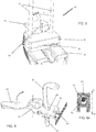
- the craniostat 20 of the present invention is shown in Figure 2 disconnected from the apparatus 1 for acquiring radiographs; when it is connected it is in the position indicated with 5 in Figure 1 .
- the craniostat is placed on its specific support 30, which is part of the patient positioning device 5; the support 30 is shown in Figure 3 .
- Figure 4 shows the coupling between the lower portion 22 of the craniostat 20 and the support 30 connecting it to the apparatus 1.
- the coupling craniostat-support is realized through four pins 45, 46 which fit in their specific holes; one of the pins is longer than the others.
- the longer pin 46 is the one ensuring the best coupling precision, thanks to minimal coupling tolerance in the respective hole, while the correct positioning and stability of the craniostat are ensured by the remaining shorter pins 45.
- the choice of different coupling tolerances is linked to production cost and to the ease of coupling by the human operator.
- a spring-loaded pressure plate acts on the pins, so as to inform the human operator that the perfect coupling craniostat-support has been reached, which ensures maximum stability.
- the spring is compressed when the pin 46 is inserted in its hole for its complete length, and its operation gives the operator an acoustic (metallic click) and tactile (friction of the vertical movement) feed-back.
- the spring-loaded pressure plate is indispensable on the long pin 46 and optional on the three short pins 45.
- the craniostat 20 can be subdivided into an upper portion 21 and a lower portion 22.
- a couple of rods 23 connects the two portions 21 and 22.
- the lower portion of the craniostat will be described.
- the lower portion of the craniostat 20 is shown resting on support 30 and complete with chin rest 52.
- the lower portion 22 of the craniostat has a fixed base 41, provided with a lever 54 for blocking bite 53.
- the chin rest 52, and the bite 54 are removable according to the needs of the different acquisitions.
- the distance d between bite 54 in its blocked position and rods 23, indicated with a dotted line, is the widest possible so as rods 23 are out from the focal trough, but inside the anti-collision cylinder. In the preferred embodiment, said distance d is 55 mm.
- the bite 54 When the lever 53 is its unblocked position (in one of its two extreme positions, e.g. totally on the left), the bite 54 is free to vertically slide in the direction indicated by the linear double arrow, and to pivot in the direction indicated by the arched double arrow.
- This disposition is particularly comfortable when positioning a patient, in that the human operator firstly unblocks the bite 54 through the lever 53 and rotates it toward one of the two rods 23, rests patient's chin on chin rest 52, and then positions the bite 54 inside patient's oral cavity vertically adjusting it.
- the bite 54 When the operator blocks the position of the bite 54 through lever 53, e.g. bringing the lever totally on the right, the bite 54 is automatically positioned in its correct sagittal position, thanks to its particular shape.
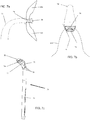
- Figure 6 shows the mechanism, contained in the base 41, for blocking the bite 54.
- the stem 61 When the lever 53 is in its unblocked position, the stem 61 is in the portion having a circular section of the hole 63 of block 62, and is therefore free to move.
- the block 62 When the lever 53 is in its blocked position, the block 62 is pushed by a cam 65 so as to compress spring 64 in the direction of the arrow.
- the portion of the hole 63 having a triangular section is coupled to the stem 61, blocking it through friction.
- the stem 61 has in its turn a triangular transversal section, which allows both a higher friction, and an auto-centring on the sagittal plane.
- the axis A-A' shows the plane of the section shown in Figure 6a and allows to better appreciate the functioning of the block.
- the hole 63 has a section partly rounded and partly triangular, and the stem 61 has a triangular section which, when blocked, is coupled to the triangular portion of hole 63.
- the cam 65 is rotated and the spring 64 pushes in a direction contrary to the arrow the block 62, freeing the coupling between the triangular section of hole 63 and of stem 61 of bite 54.
- triangular section means that a part of the delimitation surfaces of the hole, at least for a certain axial length of the bite itself, have two walls which are opposed and converging. These walls are preferably symmetrically positioned with respect to a plane containing the longitudinal axis and a diameter of hole 63, such diameter coincides with a bisector of the angle defined by the two opposed converging walls.
- the remaining part of the perimetral delimitation surface of hole 63 can have any shape, and in this embodiment is cylindrical, i.e. having circular section; the wedge-shaped portion and the cylindrical portion are seamlessly joined together.
- the stem 61 has at least for a part of its axial, longitudinal extension a section substantially analogous to the section of hole 63, but dimensionally smaller and such that said stem 61 can slide both axially, in order to adjust the bite height with respect to the chin rest, and radially, i.e. in the direction of wedging a portion of the surface of the stem itself.
- the stem has two opposed and converging walls like a wedge, preferably with the same angle of the converging walls of hole 63, also in the opposed direction of said walls, moving from the converging walls of hole 63.
- the tightening means i.e. the mechanism controlled by the lever, thrust the stem in the wedging direction of the wedge-shaped portion of said stem into the wedge-shaped portion of the hole 63, blocking said stem both in the axial direction and in its rotation around its own longitudinal axis.
- both the stem 61 and its housing hole 63 have both complementary surfaces of contact having a pre-defined angular orientation and a shape so as in tightening conditions of stem 61 in the hole 63: said surfaces come into contact and define a pre-defined angular orientation of the stem around its own axis.
- Figure 7 shows a further detail of bite 54, which is particularly useful when acquiring bite-wing radiographies, which requires the positioning of the patient at a pre-defined height.
- the stem 61 of bite 54 has a particular profile of its transversal section.
- the upper part has a substantially circular section, while about halfway its lower section becomes triangular or wedge-shaped, for the reasons explained above linked to bite auto-centring.
- the stem 61 has a horizontal recess 71.
- Inside base 41 there is also a small lever 72 pre-loaded by a spring 73, which constantly frictions, in a virtually undetectable way, against the stem 61.
- Figure 7a shows the sagittal section of bite 54 which is kept between patient's teeth
- Figure 7b shows a top view of the bite 54 end.
- the portion that the patient bites with her/his incisors is small.
- the anterior part 74 of the portion is shown, which has a net, not blunted angle, so as to ensure the stop of upper 101 and lower incisors 102, which thus lie on the same plane; in this way a panoramic image results with an as correct as possible focusing.
- the posterior part 75 is tapered and rounded to better fit patient's anatomy (Welander curve 103) and to reduce the thickness of the material crossed by X-rays. This tapering, indicated with angle ⁇ in Figure 7b , must nonetheless ensure a resting position sufficient for anterior teeth.
- said angle ⁇ is comprised between 15 and 25 degrees.
- the bite 54 it was optimized to the aim of not appearing in the radiographies, yielding an artefact. Therefore, it was built using a radiolucent plastic material. Moreover, its profile has a particular shape which allows to minimize the quantity of plastic material. As can be seen in Figure 7c , in the lower side of the arched part 76 of the bite there is a recess 77 which reduces the thickness of the bite. With the aim of maintaining its rigidity, in the bite 54 there are two ribs 78 distinct in the bite distal part, which unite in the proximal part; on said ribs the stress transmitted by the patient is discharged.
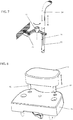
- FIG 8 the coupling between chin rest 52 and base 41 is shown.
- the coupling occurs through two pins 81 and 82 having the same length; the pin 81 is inserted in a hole which has a reduced coupling tolerance.
- the fact that the coupling of pin 82 is looser allows the operator to easily insert it into its hole, while the precise coupling of pin 81 ensures the stability of the assembly.
- the weight of patient's head is sufficient to ensure the desired immobility, and therefore there is no spring-loaded pressure plate or similar devices.
- the presence of chin rest 52 is required in practically all acquisitions, but those of temporomandibular joints, during which chin rest 52 must be removed.
- chin rest 52 when chin rest 52 is removed, it is replaced by nose support 90, on which the patient rests her/his anterior nasal spine as shown in Figure 9 .
- the nose support 90 is inserted through two pins 91 and 92 in the same holes in which pins 81 and 82 of chin rest 52 are inserted, with the same tolerances discussed above.
- a recess 93 on the craniostat 20 base 41, allows her/him to easily open and close her/his mouth, without the need of re-positioning the patient.
- the upper portion of the craniostat has to keep the patient in the desired position, and the most suitable points to this aim are considered patient's forehead (on the sagittal plane), the lateral parts of the cranium (laterally), the terminal part of the parietal bone (posteriorly).
- the upper portion 21 of the craniostat comprising a forehead rest 105 and two mobile rests 107 for the lateral portions of cranium.
- the upper portion 21 is height adjustable on rods 23.
- the upper portion 21 comprises a crossbeam 104, having holes which allow to slide on rods 23. On crossbeam 104 there is a hole in which the forehead rest 105 is slidingly inserted.
- two small arms 106 which can pivot independently of one another, so as to adjust to the width of patient's cranium, accommodating also patients having remarkable dissymmetry.
- At the end of the two arms 106 there are two small arches 107, free to independently pivot around their insertion fulcrum. Both the arms 106 and the small arches 107 have their fulcrum so as to rotate around axes substantially parallel to a vertical or longitudinal axis of patient's head.
- each arch 107 there are two, optionally removable, rubber tips or pads 108, which rest on patient's skin.
- a slot 109 which allows to insert an optional (not shown) band, generally in a soft, bendable material, which surrounds the posterior part of patient's head, so as to further immobilize her/him.
- the use of the band is optional and left to the preference of the individual human operator.
- the forehead rest 105 sliding inside the (not shown) crossbeam 104 is shown.
- the forehead rest 105 has a particular arched profile, and ends in a wide rest surface 111, on which a small, optionally removable, cushion is fixed, made of a soft material (silicone, gum, foam) to improve patient's comfort.
- the profile of rest surface 111 is slightly arched in order to better fit patient's anatomy.
- the forehead rest 105 is free to slide inside the crossbeam 104, with two, one upper and one lower, limits.
- the lower limit is due to the fact that rest 111 is larger than the seat inside which forehead rest 105 slides.
- the upper limit is due to the end-of-stroke device 112, which is provided with two small teeth 113 which perform a slight constant friction on the forehead rest 105.
- the joint between teeth 113 and recesses 114 in the upper end of forehead rest 105 prevents the accidental extraction of the forehead rest 105.
- the assembly is designed so that an intentional pressure allows the extraction of the forehead rest 105 from its seat in the crossbeam 104 for cleaning, replacement, etc.
- Optional intermediate recesses can correspond to pre-defined positions of the forehead rest 105 if needed for particular acquisitions.
- Figure 12 shows a sagittal section of the forehead rest 105 inserted in its seat in the crossbeam 104. It shows the working mechanism of the forehead rest 105. The working mechanism is highlighted in Figure 12 through the bold and dotted arrows. Basically, when the patient rests her/his forehead on the rest surface 111, she/he applies a given pressure, represented by bold arrow c. The vector of the force has two components, shown by a and b arrows, in the two points A and B, thus blocking the sliding of the forehead rest 105 due to friction.
- the forehead rest 105 there are two recesses in the points E and F so as to precisely indicate to the human operator where to apply pressure when she/he wishes to height adjust the position of the forehead rest 105. It is apparent from the profile of the forehead rest 105 that its height adjustment occurs in the direction of thickness, too.
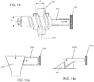
- Figure 13 shows a detail of the blocking mechanism of arm 106, inside which there is inserted a ferrule or screw nut 134 leading the block screw 133.
- the arms 106 (not shown in this Figure) have their fulcrum on a pivot 131, and this allows to adjust them according to the width of patient' s cranium, width exhibiting a wide variability.
- the blocking mechanism When the blocking mechanism is activated, the block screw 133 enters into contact with block 132, integral with crossbeam 104, generating the friction needed for blocking the system.
- the block screw 133 is rotationally inserted in the ferrule 134, which is connected with the lever 135, protruding from the structure itself in order to be used by the human operator as controls through rotation of ferrule 134.
- the rotation of the ferrule thanks to the thread and the fact that it is essentially stationary, entails an axial movement of the screw.
- the lever 135 can rotate between two extreme positions, the first of which is shown in Figure 10 (upwards) and the second of which is shown in Figure 15b (outwards).
- the lever 135 When the lever 135 is in the upward position as shown in Figure 10 , the arm 106 is free to rotate around its pivot 131 without friction.
- the lever 135 when the lever 135 is rotate downwardly, it will block, meeting block 132, in any position comprised between the two extreme positions, position which is proportional to the width of patient's cranium.
- the human operator after accommodating the patient inside the craniostat 20, adjusts the position of the arms 106 according to patient's anatomy, and then rotates the levers 135 downwardly.
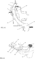
- Figure 14 shows in detail the working of the block mechanism of arms 106.
- the Figure shows a section along the rotation axis of the system ferrule 134-screw 133.
- the distance between the block screw 133 and the block 132 varies proportionally to patient's anatomy. When the patient's cranium is small, and the distance screw 133-block 132 is therefore great, to reach the block a turn of the screw 133 will be needed which is wider than the turn of the screw needed with a big cranium, and this is ensured by the length of the thread of screw 133.
- the section of the thread 141 is substantially a scalene trapezoid wherein the angles of the oblique surfaces working with the ferrule are different.
- Figure 14 shows the preferred embodiment, based on a surface coupling system which blocks the moving parts by friction. However, based on the same principle there are many other possible embodiments, some of which are e.g. shown in Figures 14a and 14b .
- Figure 14a shows a wedge device, wherein the movement of the rigid block 133a, conceptually equivalent to screw 133, is blocked by a wedge 142. According to the distance rigid block 133a-block 132a, the wedge 142 will be lowered of a variable quantity, proportional to patient's anatomy.
- Figure 14b shows a saw tooth device, wherein the movement of the rigid block 133b, conceptually equivalent to screw 133, is blocked by a specular saw tooth 143.
- the disadvantage of this configuration is that it works only discontinuously, and does not allow a continuous adjustment.
- Figures 15a and 15b show the horizontal section of a cranium of a very big patient 100a and of a very small patient 100b, respectively.
- the comparison between the two Figures allows to appreciate the different position of forehead rest 105 and of arms 106.
- forehead rest 105 is positioned upwardly, and thanks to its arched profile, protrudes little with respect to crossbeam 104.
- the arms 106 are in their maximal outward extension, and therefore the levers 135 are very near to their upward unblock position.
- forehead rest 105 is positioned downwardly in its end-of-stroke position, and protrudes markedly towards patient's forehead, while the arms 106 are in their inward maximal extension, and therefore the levers 135 are in their extreme block position, protruding outwardly.
Landscapes
- Health & Medical Sciences (AREA)
- Life Sciences & Earth Sciences (AREA)
- Engineering & Computer Science (AREA)
- Medical Informatics (AREA)
- Optics & Photonics (AREA)
- General Health & Medical Sciences (AREA)
- Veterinary Medicine (AREA)
- Public Health (AREA)
- Biophysics (AREA)
- High Energy & Nuclear Physics (AREA)
- Physics & Mathematics (AREA)
- Nuclear Medicine, Radiotherapy & Molecular Imaging (AREA)
- Animal Behavior & Ethology (AREA)
- Pathology (AREA)
- Radiology & Medical Imaging (AREA)
- Biomedical Technology (AREA)
- Heart & Thoracic Surgery (AREA)
- Molecular Biology (AREA)
- Surgery (AREA)
- Dentistry (AREA)
- Oral & Maxillofacial Surgery (AREA)
- General Engineering & Computer Science (AREA)
- Neurology (AREA)
- Neurosurgery (AREA)
- Mechanical Engineering (AREA)
- Apparatus For Radiation Diagnosis (AREA)
- Dental Tools And Instruments Or Auxiliary Dental Instruments (AREA)
Claims (11)
- Kraniostat (20) für ein extraorales Dentalröntgengerät (1), umfassend eine feste Basis (41) in dem unteren Abschnitt des Kraniostaten, welche Basis einen Hebel, einen Kinnhalter (52) und einen Bissblock aufweist und die beiden letzteren vorzugsweise aus einem Träger einer Patientenpositionierungsvorrichtung entfernbar sind, Spannmittel zur Blockierung des Bissstückes (54), welche Spannmittel einen Hebel (53) und einen Block (62) mit einer Bohrung (63) zum Aufnehmen eines Schaftes (61) des Bissstückes (54) aufweisen, wobei der Block (62) eine Ebene definiert, gekennzeichnet durch den Schaft (61) umfassend einen unteren Abschnitt mit einem dreieckigen oder keilförmigen Querschnitt, der Zentrierflächen mit einer vorgegebenen Ausrichtung bezüglich ihrer eigenen Längsachse definiert, wobei das Bissstück (54) dafür ausgelegt ist, in eine Blockierposition durch Spannen der Zentrierflächen an Spannflächen der Bohrung (63) blockiert zu werden und die Bohrung (63) weiterhin eine vorgegebene eine Bissstück-Zentrierposition definierende Ausrichtung aufweist, so dass im Spannzustand das Bissstück (54) automatisch in die Zentrierposition auf der Ebene der Blockes (62) gebracht wird.
- Kraniostat (20) nach Anspruch 1, wobei die Spannflächen der Bohrung (63) einen Abschnitt der Bohrung (3) bilden, der einen keil- oder dreieckartigen Querschnitt an den Spannflächen aufweist, wobei die Zentrierflächen des Schaftes (61) den dreieckigen oder keilförmigen Querschnitt des Schaftes (61) bestimmen, der mit den Spannflächen der Bohrung (63) mit keilartigem oder dreieckartigem Querschnitt zusammenwirkt.
- Kraniostat (20) nach Anspruch 1 oder 2, wobei der Endabschnitt des Bissstückes (54)- einen Vorderteil (74) mit einem sauberen, nicht
stumpfen Winkel, um den Anschlag von oberen Schneidezähnen (101) und unteren Schneidezähnen (102), die somit auf derselben Ebene liegen, zu gewährleisten;- einen verjüngten und verrundeten Hinterteil (75),zur besseren Anpassung an die Anatomie des Patienten (Welander-Kurve (103)) und zur Verringerung der Dicke des von Röntgenstrahlen durchdringenden Materials,
aufweist. - Kraniostat (20) nach einem oder mehreren der vorhergehenden Ansprüche, wobei das Bissstück (54) aus strahlendurchlässigem Kunststoffmaterial besteht, mit einer die Dicke des Bissstückes reduzierenden Ausnehmung (77) und zwei Rippen (78), die im distalen Teil des Bissstückes voneinander getrennt sind und in seinem proximalen Teil sich zusammentreffen, wobei auf diesen Rippen die vom Patienten übertragene Spannung abgegeben wird.
- Kraniostat (20) nach einem oder mehreren der vorhergehenden Ansprüche, wobei das Bissstück (54) einen Durchbruch (71) aufweist, der dem menschlichen Bediener eine Rückkopplung zur exakten Positionierung des Bissstückes (54) zur Aufnahme von Bissflügel-Radiographien gibt.
- Kraniostat (20) nach einem oder mehreren der vorhergehenden Ansprüche, wobei der Kraniostat (20) selbst von seinem Träger (30) und/oder der Kinnhalter (52) von dem unteren Teil (22) des Kraniostaten (20) entfernbar sind; die Kopplung des Kraniostaten (20) mit der Basis (30) und/oder zwischen dem unteren Abschnitt (22) des Kraniostaten und dem Kinnhalter (52) durch das Vorhandensein von mindestens zwei Stiften (45, 46; 81, 82) erfolgt; einer der Stifte (46, 81) eine gegenüber dem anderen Stift/den anderen Stiften (45, 82) niedrigere Kupplungstoleranz und/oder größere Länge aufweist.
- Verfahren zum Positionieren eines Patienten in einem extraoralen Dentalröntgengerät (1), das einen Kraniostat nach Anspruch 1 umfasst, wobei das Verfahren die folgenden Schritte umfasst:- Positionierung eines Patienten (100) durch einen Bediener in dem Gerät (1);- Einstellung durch den Bediener zunächst des unteren Abschnittes (22) des Kraniostats (20);- Aufforderung des Patienten sein Kinn auf den Kinnhalter (52) aufzulegen;- Einstellung der Höhe der Gleitsäule (4), um den Kopf des Patienten geeignet zu neigen;- Aufforderung des Patienten seinen Mund zu öffnen;- Drehen und Absenken des Bissstückes (54), bis der Vorderteil (74) des Bissstückes (54) mit den unteren Schneidezähnen (102) des Patienten in Kontakt steht;- Aufforderung des Patienten durch den Bediener das Bissstück (54) zu beißen, bis zum Anschlag seiner Schneidezähne an dem Vorderteil (74);wobei
der Bediener die Position des Bissstückes (54) mit einem Hebel (53) des Kraniostaten vertikal und sagittal blockiert. - Verfahren zum Positionieren eines Patienten in einem extraoralen Dentalröntgengerät (1) zur Aufnahme einer Bissflügel-Radiographie nach Anspruch 7, weiter umfassend die Schritte des Blockierens des Bissstückes (54) in einer vorbestimmten Höhe, dank der Rückkopplung durch das Vorhandensein eines horizontalen Durchbruches (71).
- Kraniostat (20) für ein extraorales Dentalröntgengerät (1), nach einem oder mehreren der vorhergehenden Ansprüche 1 bis 6, umfassend eine feste Basis (41) in dem unteren Abschnitt des Kraniostats, welche Basis einen Hebel, einen Kinnhalter (52) und ein Bissstück (54) aufweist und die beiden letzteren vorzugsweise aus einem Träger einer Patientenpositionierungsvorrichtung entfernbar sind, dadurch gekennzeichnet, dass ein Endabschnitt des Bissstückes (54):- einen Vorderteil (74) mit einem sauberen, nicht
stumpfen Winkel, um den Anschlag von oberen Schneidezähnen (101) und unteren Schneidezähnen (102), die somit auf derselben Ebene liegen, zu gewährleisten;- einen verjüngten und verrundeten Hinterteil (75),zur besseren Anpassung an die Anatomie des Patienten (Welander-Kurve (103)) und zur Verringerung der Dicke des von Röntgenstrahlen durchdringenden Materials,
aufweist. - Kraniostat (20) für ein extraorales Dentalröntgengerät (1), nach einem oder mehreren der vorhergehenden Ansprüche 1 bis 6, umfassend eine feste Basis (41) in dem unteren Abschnitt des Kraniostats, welche Basis einen Hebel, einen Kinnhalter (52) und einen Bissblock aufweist und die beiden letzteren vorzugsweise aus einem Träger einer Patientenpositionierungsvorrichtung entfernbar sind, wobei der Kraniostat (20) selbst von seinem Träger (30) und/oder der Kinnhalter (52) von der Basis (41) des Kraniostaten (20) entfernbar sind; die Kopplung des Kraniostaten (20) mit der Basis (30) und/oder zwischen der Basis (41) des Kraniostaten und dem Kinnhalter (52) durch das Vorhandensein von mindestens zwei Stiften (45, 46; 81, 82) erfolgt; einer der Stifte (46, 81) eine gegenüber dem anderen Stift/den anderen Stiften (45, 82) niedrigere Kopplungstoleranz und/oder größere Länge aufweist.
- Kraniostat nach den Ansprüchen 9 oder 10 zur Durchführung eines Verfahrens nach den Ansprüchen 7 oder 8.
Applications Claiming Priority (1)
| Application Number | Priority Date | Filing Date | Title |
|---|---|---|---|
| ITBO20140220 | 2014-04-17 |
Publications (3)
| Publication Number | Publication Date |
|---|---|
| EP2942014A2 EP2942014A2 (de) | 2015-11-11 |
| EP2942014A3 EP2942014A3 (de) | 2016-03-02 |
| EP2942014B1 true EP2942014B1 (de) | 2018-03-21 |
Family
ID=50897704
Family Applications (1)
| Application Number | Title | Priority Date | Filing Date |
|---|---|---|---|
| EP15163924.2A Active EP2942014B1 (de) | 2014-04-17 | 2015-04-16 | Craniostat zur erfassung extraoraler dentaler röntgenaufnahmen |
Country Status (4)
| Country | Link |
|---|---|
| US (1) | US9439609B2 (de) |
| EP (1) | EP2942014B1 (de) |
| KR (1) | KR101813472B1 (de) |
| CN (1) | CN104997530B (de) |
Families Citing this family (7)
| Publication number | Priority date | Publication date | Assignee | Title |
|---|---|---|---|---|
| USD810304S1 (en) * | 2014-04-24 | 2018-02-13 | Cefla Societá Cooperativa | Head support |
| ES2983077T3 (es) * | 2015-02-27 | 2024-10-21 | Trophy | Bloque de mordida para dispositivo de formación de imágenes CBCT |
| ITUA20162728A1 (it) * | 2016-04-20 | 2017-10-20 | Cefla Soc Cooperativa | Cefalostato |
| FI127695B (fi) * | 2017-03-17 | 2018-12-14 | Planmeca Oy | Röntgenkuvauslaite ja potilastukijärjestely |
| CN109480895B (zh) * | 2018-11-29 | 2024-05-21 | 枣庄市立医院 | 一种医学影像学普通x线摄片体位辅助装置 |
| CN113796876B (zh) * | 2020-06-16 | 2025-08-29 | 合肥美亚光电技术股份有限公司 | 用于口腔cbct的定位装置和口腔cbct |
| CN113967031B (zh) * | 2021-10-29 | 2024-03-01 | 陈勇 | 一种ct检查头颅的头部固定装置 |
Family Cites Families (15)
| Publication number | Priority date | Publication date | Assignee | Title |
|---|---|---|---|---|
| US3936641A (en) | 1974-10-21 | 1976-02-03 | Pennwalt Corporation | Head immobilizing device for panoramic x-ray apparatus |
| FI92973C (fi) * | 1991-05-06 | 1995-02-10 | Planmeca Oy | Menetelmä ja laite panoraamaröntgenkuvauksessa |
| CN2376267Y (zh) * | 1999-06-04 | 2000-05-03 | 威海市文登中心医院 | 一种曲面x光机咬颌器 |
| DE102004041440A1 (de) * | 2004-08-27 | 2006-03-02 | Dürr Dental GmbH & Co. KG | Verfahren zur Bestimmung der Soll-Relativlage eines Patienten in einem dentalen Panorama-Röntgengerät bzw. der Soll-Bahn, auf welcher dieses bezüglich eines Patienten bewegt wird sowie eine dafür geeignete Vorrichtung |
| US7195395B2 (en) * | 2005-02-28 | 2007-03-27 | Kerrhawe Sa | Dental sensor clamp |
| US20060227939A1 (en) * | 2005-04-11 | 2006-10-12 | Gendex Corporation | Bite piece for a dental x-ray system |
| DE102006021639A1 (de) * | 2006-05-08 | 2007-11-15 | Sirona Dental Systems Gmbh | Dentales Röntgengerät, umfassend eine an einem Trägerteil angebrachte Patientenpositionierung mit einer Stirnstütze |
| WO2011013771A1 (ja) * | 2009-07-30 | 2011-02-03 | 株式会社テレシステムズ | 放射線撮像装置及び放射線による撮像方法 |
| FI126561B (fi) * | 2010-02-23 | 2017-02-15 | Planmeca Oy | Hammaslääketieteellisen röntgenlaitteiston potilastuki |
| CN201719264U (zh) * | 2010-06-11 | 2011-01-26 | 天津医药集团众健康达医疗器械有限公司 | 全景x射线机颌托 |
| US9642582B2 (en) | 2011-07-22 | 2017-05-09 | Trophy | Shield for patient positioning in extra-oral imaging |
| CN203524692U (zh) * | 2013-07-01 | 2014-04-09 | 四川九九天目医疗器械有限公司 | 一种用于口腔ct的下颌固定装置 |
| CN203388877U (zh) * | 2013-07-19 | 2014-01-15 | 薛永福 | 放射科全景牙摄影定位器 |
| KR101838349B1 (ko) * | 2014-04-17 | 2018-03-13 | 쎄플라 쏘씨에타 쿠퍼라티바 | 구강외 치과 방사선영상을 획득하기 위한 두개 고정기 |
| KR101796350B1 (ko) * | 2014-04-17 | 2017-11-09 | 쎄플라 쏘씨에타 쿠퍼라티바 | 구강외 치과 방사선영상을 획득하기 위한 두개 고정기 |
-
2015
- 2015-04-10 KR KR1020150050836A patent/KR101813472B1/ko active Active
- 2015-04-15 US US14/687,027 patent/US9439609B2/en active Active
- 2015-04-16 EP EP15163924.2A patent/EP2942014B1/de active Active
- 2015-04-17 CN CN201510184617.8A patent/CN104997530B/zh active Active
Non-Patent Citations (1)
| Title |
|---|
| None * |
Also Published As
| Publication number | Publication date |
|---|---|
| EP2942014A3 (de) | 2016-03-02 |
| KR101813472B1 (ko) | 2017-12-29 |
| US20150297154A1 (en) | 2015-10-22 |
| KR20150120295A (ko) | 2015-10-27 |
| US9439609B2 (en) | 2016-09-13 |
| CN104997530B (zh) | 2019-08-20 |
| EP2942014A2 (de) | 2015-11-11 |
| CN104997530A (zh) | 2015-10-28 |
Similar Documents
| Publication | Publication Date | Title |
|---|---|---|
| EP2942014B1 (de) | Craniostat zur erfassung extraoraler dentaler röntgenaufnahmen | |
| EP2932903B1 (de) | Craniostat zur erfassung extraoraler dentaler röntgenaufnahmen | |
| EP2932904B1 (de) | Craniostat zur erfassung extraoraler dentaler röntgenaufnahmen | |
| EP3746014B1 (de) | Orale schlafapnoe-vorrichtung mit konnektoren | |
| KR20170012244A (ko) | 치과교정 장치 및 치과교정 장치의 제조 방법 | |
| US11701071B2 (en) | Dental bite block for 2D imaging | |
| KR102095273B1 (ko) | 인상 트레이 및 상기 인상 트레이와 ct 영상 촬영 장치를 이용한 틀니 제조 방법 | |
| EP3235436B1 (de) | Kephalostat | |
| JP3615733B2 (ja) | 口内法x線撮影用補助具 | |
| US4144460A (en) | Method and device for radiographing human jaw joints | |
| JP6069678B2 (ja) | X線撮影装置の整列バイト及びこれを有するx線撮影装置 | |
| JPH0446577B2 (de) | ||
| US3307262A (en) | Device for locating the exact center of the condyle by using extra oral radiography | |
| JP6970209B2 (ja) | X線撮像装置及び患者支持体 | |
| Carver | Orthopantomography and cephalometry | |
| HK40018966A (en) | X-ray imaging apparatus and patient support | |
| EP0031810A1 (de) | Verfahren und vorrichtung für röntgenaufnahmen menschlicher kiefergelenke | |
| HK40019000A (en) | X-ray imaging apparatus and patient support arrangement |
Legal Events
| Date | Code | Title | Description |
|---|---|---|---|
| PUAI | Public reference made under article 153(3) epc to a published international application that has entered the european phase |
Free format text: ORIGINAL CODE: 0009012 |
|
| AK | Designated contracting states |
Kind code of ref document: A2 Designated state(s): AL AT BE BG CH CY CZ DE DK EE ES FI FR GB GR HR HU IE IS IT LI LT LU LV MC MK MT NL NO PL PT RO RS SE SI SK SM TR |
|
| AX | Request for extension of the european patent |
Extension state: BA ME |
|
| PUAL | Search report despatched |
Free format text: ORIGINAL CODE: 0009013 |
|
| RIC1 | Information provided on ipc code assigned before grant |
Ipc: A61B 6/00 20060101ALI20160120BHEP Ipc: F16B 2/18 20060101ALI20160120BHEP Ipc: A61B 6/04 20060101AFI20160120BHEP Ipc: A61B 6/14 20060101ALI20160120BHEP |
|
| AK | Designated contracting states |
Kind code of ref document: A3 Designated state(s): AL AT BE BG CH CY CZ DE DK EE ES FI FR GB GR HR HU IE IS IT LI LT LU LV MC MK MT NL NO PL PT RO RS SE SI SK SM TR |
|
| AX | Request for extension of the european patent |
Extension state: BA ME |
|
| 17P | Request for examination filed |
Effective date: 20160829 |
|
| RBV | Designated contracting states (corrected) |
Designated state(s): AL AT BE BG CH CY CZ DE DK EE ES FI FR GB GR HR HU IE IS IT LI LT LU LV MC MK MT NL NO PL PT RO RS SE SI SK SM TR |
|
| GRAP | Despatch of communication of intention to grant a patent |
Free format text: ORIGINAL CODE: EPIDOSNIGR1 |
|
| INTG | Intention to grant announced |
Effective date: 20171030 |
|
| GRAS | Grant fee paid |
Free format text: ORIGINAL CODE: EPIDOSNIGR3 |
|
| GRAA | (expected) grant |
Free format text: ORIGINAL CODE: 0009210 |
|
| AK | Designated contracting states |
Kind code of ref document: B1 Designated state(s): AL AT BE BG CH CY CZ DE DK EE ES FI FR GB GR HR HU IE IS IT LI LT LU LV MC MK MT NL NO PL PT RO RS SE SI SK SM TR |
|
| REG | Reference to a national code |
Ref country code: GB Ref legal event code: FG4D |
|
| REG | Reference to a national code |
Ref country code: CH Ref legal event code: EP |
|
| REG | Reference to a national code |
Ref country code: AT Ref legal event code: REF Ref document number: 980221 Country of ref document: AT Kind code of ref document: T Effective date: 20180415 |
|
| REG | Reference to a national code |
Ref country code: IE Ref legal event code: FG4D |
|
| REG | Reference to a national code |
Ref country code: DE Ref legal event code: R096 Ref document number: 602015008969 Country of ref document: DE |
|
| REG | Reference to a national code |
Ref country code: FR Ref legal event code: PLFP Year of fee payment: 4 |
|
| REG | Reference to a national code |
Ref country code: NL Ref legal event code: MP Effective date: 20180321 |
|
| PG25 | Lapsed in a contracting state [announced via postgrant information from national office to epo] |
Ref country code: CY Free format text: LAPSE BECAUSE OF FAILURE TO SUBMIT A TRANSLATION OF THE DESCRIPTION OR TO PAY THE FEE WITHIN THE PRESCRIBED TIME-LIMIT Effective date: 20180321 Ref country code: LT Free format text: LAPSE BECAUSE OF FAILURE TO SUBMIT A TRANSLATION OF THE DESCRIPTION OR TO PAY THE FEE WITHIN THE PRESCRIBED TIME-LIMIT Effective date: 20180321 Ref country code: HR Free format text: LAPSE BECAUSE OF FAILURE TO SUBMIT A TRANSLATION OF THE DESCRIPTION OR TO PAY THE FEE WITHIN THE PRESCRIBED TIME-LIMIT Effective date: 20180321 Ref country code: NO Free format text: LAPSE BECAUSE OF FAILURE TO SUBMIT A TRANSLATION OF THE DESCRIPTION OR TO PAY THE FEE WITHIN THE PRESCRIBED TIME-LIMIT Effective date: 20180621 |
|
| REG | Reference to a national code |
Ref country code: LT Ref legal event code: MG4D |
|
| REG | Reference to a national code |
Ref country code: AT Ref legal event code: MK05 Ref document number: 980221 Country of ref document: AT Kind code of ref document: T Effective date: 20180321 |
|
| PG25 | Lapsed in a contracting state [announced via postgrant information from national office to epo] |
Ref country code: GR Free format text: LAPSE BECAUSE OF FAILURE TO SUBMIT A TRANSLATION OF THE DESCRIPTION OR TO PAY THE FEE WITHIN THE PRESCRIBED TIME-LIMIT Effective date: 20180622 Ref country code: RS Free format text: LAPSE BECAUSE OF FAILURE TO SUBMIT A TRANSLATION OF THE DESCRIPTION OR TO PAY THE FEE WITHIN THE PRESCRIBED TIME-LIMIT Effective date: 20180321 Ref country code: LV Free format text: LAPSE BECAUSE OF FAILURE TO SUBMIT A TRANSLATION OF THE DESCRIPTION OR TO PAY THE FEE WITHIN THE PRESCRIBED TIME-LIMIT Effective date: 20180321 Ref country code: SE Free format text: LAPSE BECAUSE OF FAILURE TO SUBMIT A TRANSLATION OF THE DESCRIPTION OR TO PAY THE FEE WITHIN THE PRESCRIBED TIME-LIMIT Effective date: 20180321 Ref country code: BG Free format text: LAPSE BECAUSE OF FAILURE TO SUBMIT A TRANSLATION OF THE DESCRIPTION OR TO PAY THE FEE WITHIN THE PRESCRIBED TIME-LIMIT Effective date: 20180621 |
|
| PG25 | Lapsed in a contracting state [announced via postgrant information from national office to epo] |
Ref country code: PL Free format text: LAPSE BECAUSE OF FAILURE TO SUBMIT A TRANSLATION OF THE DESCRIPTION OR TO PAY THE FEE WITHIN THE PRESCRIBED TIME-LIMIT Effective date: 20180321 Ref country code: AL Free format text: LAPSE BECAUSE OF FAILURE TO SUBMIT A TRANSLATION OF THE DESCRIPTION OR TO PAY THE FEE WITHIN THE PRESCRIBED TIME-LIMIT Effective date: 20180321 Ref country code: ES Free format text: LAPSE BECAUSE OF FAILURE TO SUBMIT A TRANSLATION OF THE DESCRIPTION OR TO PAY THE FEE WITHIN THE PRESCRIBED TIME-LIMIT Effective date: 20180321 Ref country code: EE Free format text: LAPSE BECAUSE OF FAILURE TO SUBMIT A TRANSLATION OF THE DESCRIPTION OR TO PAY THE FEE WITHIN THE PRESCRIBED TIME-LIMIT Effective date: 20180321 Ref country code: RO Free format text: LAPSE BECAUSE OF FAILURE TO SUBMIT A TRANSLATION OF THE DESCRIPTION OR TO PAY THE FEE WITHIN THE PRESCRIBED TIME-LIMIT Effective date: 20180321 Ref country code: NL Free format text: LAPSE BECAUSE OF FAILURE TO SUBMIT A TRANSLATION OF THE DESCRIPTION OR TO PAY THE FEE WITHIN THE PRESCRIBED TIME-LIMIT Effective date: 20180321 |
|
| PG25 | Lapsed in a contracting state [announced via postgrant information from national office to epo] |
Ref country code: AT Free format text: LAPSE BECAUSE OF FAILURE TO SUBMIT A TRANSLATION OF THE DESCRIPTION OR TO PAY THE FEE WITHIN THE PRESCRIBED TIME-LIMIT Effective date: 20180321 Ref country code: CZ Free format text: LAPSE BECAUSE OF FAILURE TO SUBMIT A TRANSLATION OF THE DESCRIPTION OR TO PAY THE FEE WITHIN THE PRESCRIBED TIME-LIMIT Effective date: 20180321 Ref country code: SK Free format text: LAPSE BECAUSE OF FAILURE TO SUBMIT A TRANSLATION OF THE DESCRIPTION OR TO PAY THE FEE WITHIN THE PRESCRIBED TIME-LIMIT Effective date: 20180321 Ref country code: SM Free format text: LAPSE BECAUSE OF FAILURE TO SUBMIT A TRANSLATION OF THE DESCRIPTION OR TO PAY THE FEE WITHIN THE PRESCRIBED TIME-LIMIT Effective date: 20180321 |
|
| REG | Reference to a national code |
Ref country code: CH Ref legal event code: PL |
|
| REG | Reference to a national code |
Ref country code: BE Ref legal event code: MM Effective date: 20180430 |
|
| PG25 | Lapsed in a contracting state [announced via postgrant information from national office to epo] |
Ref country code: PT Free format text: LAPSE BECAUSE OF FAILURE TO SUBMIT A TRANSLATION OF THE DESCRIPTION OR TO PAY THE FEE WITHIN THE PRESCRIBED TIME-LIMIT Effective date: 20180723 |
|
| REG | Reference to a national code |
Ref country code: DE Ref legal event code: R097 Ref document number: 602015008969 Country of ref document: DE |
|
| REG | Reference to a national code |
Ref country code: IE Ref legal event code: MM4A |
|
| PLBE | No opposition filed within time limit |
Free format text: ORIGINAL CODE: 0009261 |
|
| STAA | Information on the status of an ep patent application or granted ep patent |
Free format text: STATUS: NO OPPOSITION FILED WITHIN TIME LIMIT |
|
| PG25 | Lapsed in a contracting state [announced via postgrant information from national office to epo] |
Ref country code: DK Free format text: LAPSE BECAUSE OF FAILURE TO SUBMIT A TRANSLATION OF THE DESCRIPTION OR TO PAY THE FEE WITHIN THE PRESCRIBED TIME-LIMIT Effective date: 20180321 Ref country code: LU Free format text: LAPSE BECAUSE OF NON-PAYMENT OF DUE FEES Effective date: 20180416 Ref country code: MC Free format text: LAPSE BECAUSE OF FAILURE TO SUBMIT A TRANSLATION OF THE DESCRIPTION OR TO PAY THE FEE WITHIN THE PRESCRIBED TIME-LIMIT Effective date: 20180321 |
|
| 26N | No opposition filed |
Effective date: 20190102 |
|
| PG25 | Lapsed in a contracting state [announced via postgrant information from national office to epo] |
Ref country code: CH Free format text: LAPSE BECAUSE OF NON-PAYMENT OF DUE FEES Effective date: 20180430 Ref country code: BE Free format text: LAPSE BECAUSE OF NON-PAYMENT OF DUE FEES Effective date: 20180430 Ref country code: LI Free format text: LAPSE BECAUSE OF NON-PAYMENT OF DUE FEES Effective date: 20180430 |
|
| PG25 | Lapsed in a contracting state [announced via postgrant information from national office to epo] |
Ref country code: IE Free format text: LAPSE BECAUSE OF NON-PAYMENT OF DUE FEES Effective date: 20180416 |
|
| PG25 | Lapsed in a contracting state [announced via postgrant information from national office to epo] |
Ref country code: SI Free format text: LAPSE BECAUSE OF FAILURE TO SUBMIT A TRANSLATION OF THE DESCRIPTION OR TO PAY THE FEE WITHIN THE PRESCRIBED TIME-LIMIT Effective date: 20180321 |
|
| GBPC | Gb: european patent ceased through non-payment of renewal fee |
Effective date: 20190416 |
|
| PG25 | Lapsed in a contracting state [announced via postgrant information from national office to epo] |
Ref country code: GB Free format text: LAPSE BECAUSE OF NON-PAYMENT OF DUE FEES Effective date: 20190416 Ref country code: MT Free format text: LAPSE BECAUSE OF NON-PAYMENT OF DUE FEES Effective date: 20180416 |
|
| PG25 | Lapsed in a contracting state [announced via postgrant information from national office to epo] |
Ref country code: TR Free format text: LAPSE BECAUSE OF FAILURE TO SUBMIT A TRANSLATION OF THE DESCRIPTION OR TO PAY THE FEE WITHIN THE PRESCRIBED TIME-LIMIT Effective date: 20180321 |
|
| PG25 | Lapsed in a contracting state [announced via postgrant information from national office to epo] |
Ref country code: MK Free format text: LAPSE BECAUSE OF NON-PAYMENT OF DUE FEES Effective date: 20180321 Ref country code: HU Free format text: LAPSE BECAUSE OF FAILURE TO SUBMIT A TRANSLATION OF THE DESCRIPTION OR TO PAY THE FEE WITHIN THE PRESCRIBED TIME-LIMIT; INVALID AB INITIO Effective date: 20150416 |
|
| PG25 | Lapsed in a contracting state [announced via postgrant information from national office to epo] |
Ref country code: IS Free format text: LAPSE BECAUSE OF FAILURE TO SUBMIT A TRANSLATION OF THE DESCRIPTION OR TO PAY THE FEE WITHIN THE PRESCRIBED TIME-LIMIT Effective date: 20180721 |
|
| PGFP | Annual fee paid to national office [announced via postgrant information from national office to epo] |
Ref country code: FI Payment date: 20250319 Year of fee payment: 11 |
|
| PGFP | Annual fee paid to national office [announced via postgrant information from national office to epo] |
Ref country code: FR Payment date: 20250319 Year of fee payment: 11 |
|
| PGFP | Annual fee paid to national office [announced via postgrant information from national office to epo] |
Ref country code: IT Payment date: 20250319 Year of fee payment: 11 |
|
| PGFP | Annual fee paid to national office [announced via postgrant information from national office to epo] |
Ref country code: DE Payment date: 20250319 Year of fee payment: 11 |