EP2941341B1 - Verfahren zur genauen registrierung von verbundlaminaten - Google Patents
Verfahren zur genauen registrierung von verbundlaminaten Download PDFInfo
- Publication number
- EP2941341B1 EP2941341B1 EP13799454.7A EP13799454A EP2941341B1 EP 2941341 B1 EP2941341 B1 EP 2941341B1 EP 13799454 A EP13799454 A EP 13799454A EP 2941341 B1 EP2941341 B1 EP 2941341B1
- Authority
- EP
- European Patent Office
- Prior art keywords
- laminate
- layment
- readable element
- readable
- providing
- Prior art date
- Legal status (The legal status is an assumption and is not a legal conclusion. Google has not performed a legal analysis and makes no representation as to the accuracy of the status listed.)
- Active
Links
Images




Classifications
-
- B—PERFORMING OPERATIONS; TRANSPORTING
- B29—WORKING OF PLASTICS; WORKING OF SUBSTANCES IN A PLASTIC STATE IN GENERAL
- B29C—SHAPING OR JOINING OF PLASTICS; SHAPING OF MATERIAL IN A PLASTIC STATE, NOT OTHERWISE PROVIDED FOR; AFTER-TREATMENT OF THE SHAPED PRODUCTS, e.g. REPAIRING
- B29C70/00—Shaping composites, i.e. plastics material comprising reinforcements, fillers or preformed parts, e.g. inserts
- B29C70/04—Shaping composites, i.e. plastics material comprising reinforcements, fillers or preformed parts, e.g. inserts comprising reinforcements only, e.g. self-reinforcing plastics
- B29C70/28—Shaping operations therefor
- B29C70/30—Shaping by lay-up, i.e. applying fibres, tape or broadsheet on a mould, former or core; Shaping by spray-up, i.e. spraying of fibres on a mould, former or core
-
- B—PERFORMING OPERATIONS; TRANSPORTING
- B29—WORKING OF PLASTICS; WORKING OF SUBSTANCES IN A PLASTIC STATE IN GENERAL
- B29C—SHAPING OR JOINING OF PLASTICS; SHAPING OF MATERIAL IN A PLASTIC STATE, NOT OTHERWISE PROVIDED FOR; AFTER-TREATMENT OF THE SHAPED PRODUCTS, e.g. REPAIRING
- B29C70/00—Shaping composites, i.e. plastics material comprising reinforcements, fillers or preformed parts, e.g. inserts
- B29C70/04—Shaping composites, i.e. plastics material comprising reinforcements, fillers or preformed parts, e.g. inserts comprising reinforcements only, e.g. self-reinforcing plastics
- B29C70/28—Shaping operations therefor
- B29C70/54—Component parts, details or accessories; Auxiliary operations, e.g. feeding or storage of prepregs or SMC after impregnation or during ageing
- B29C70/543—Fixing the position or configuration of fibrous reinforcements before or during moulding
-
- B—PERFORMING OPERATIONS; TRANSPORTING
- B32—LAYERED PRODUCTS
- B32B—LAYERED PRODUCTS, i.e. PRODUCTS BUILT-UP OF STRATA OF FLAT OR NON-FLAT, e.g. CELLULAR OR HONEYCOMB, FORM
- B32B41/00—Arrangements for controlling or monitoring lamination processes; Safety arrangements
-
- Y—GENERAL TAGGING OF NEW TECHNOLOGICAL DEVELOPMENTS; GENERAL TAGGING OF CROSS-SECTIONAL TECHNOLOGIES SPANNING OVER SEVERAL SECTIONS OF THE IPC; TECHNICAL SUBJECTS COVERED BY FORMER USPC CROSS-REFERENCE ART COLLECTIONS [XRACs] AND DIGESTS
- Y02—TECHNOLOGIES OR APPLICATIONS FOR MITIGATION OR ADAPTATION AGAINST CLIMATE CHANGE
- Y02T—CLIMATE CHANGE MITIGATION TECHNOLOGIES RELATED TO TRANSPORTATION
- Y02T50/00—Aeronautics or air transport
- Y02T50/40—Weight reduction
-
- Y—GENERAL TAGGING OF NEW TECHNOLOGICAL DEVELOPMENTS; GENERAL TAGGING OF CROSS-SECTIONAL TECHNOLOGIES SPANNING OVER SEVERAL SECTIONS OF THE IPC; TECHNICAL SUBJECTS COVERED BY FORMER USPC CROSS-REFERENCE ART COLLECTIONS [XRACs] AND DIGESTS
- Y10—TECHNICAL SUBJECTS COVERED BY FORMER USPC
- Y10T—TECHNICAL SUBJECTS COVERED BY FORMER US CLASSIFICATION
- Y10T29/00—Metal working
- Y10T29/49—Method of mechanical manufacture
- Y10T29/49616—Structural member making
- Y10T29/49622—Vehicular structural member making
-
- Y—GENERAL TAGGING OF NEW TECHNOLOGICAL DEVELOPMENTS; GENERAL TAGGING OF CROSS-SECTIONAL TECHNOLOGIES SPANNING OVER SEVERAL SECTIONS OF THE IPC; TECHNICAL SUBJECTS COVERED BY FORMER USPC CROSS-REFERENCE ART COLLECTIONS [XRACs] AND DIGESTS
- Y10—TECHNICAL SUBJECTS COVERED BY FORMER USPC
- Y10T—TECHNICAL SUBJECTS COVERED BY FORMER US CLASSIFICATION
- Y10T29/00—Metal working
- Y10T29/49—Method of mechanical manufacture
- Y10T29/49764—Method of mechanical manufacture with testing or indicating
-
- Y—GENERAL TAGGING OF NEW TECHNOLOGICAL DEVELOPMENTS; GENERAL TAGGING OF CROSS-SECTIONAL TECHNOLOGIES SPANNING OVER SEVERAL SECTIONS OF THE IPC; TECHNICAL SUBJECTS COVERED BY FORMER USPC CROSS-REFERENCE ART COLLECTIONS [XRACs] AND DIGESTS
- Y10—TECHNICAL SUBJECTS COVERED BY FORMER USPC
- Y10T—TECHNICAL SUBJECTS COVERED BY FORMER US CLASSIFICATION
- Y10T29/00—Metal working
- Y10T29/49—Method of mechanical manufacture
- Y10T29/49764—Method of mechanical manufacture with testing or indicating
- Y10T29/49771—Quantitative measuring or gauging
-
- Y—GENERAL TAGGING OF NEW TECHNOLOGICAL DEVELOPMENTS; GENERAL TAGGING OF CROSS-SECTIONAL TECHNOLOGIES SPANNING OVER SEVERAL SECTIONS OF THE IPC; TECHNICAL SUBJECTS COVERED BY FORMER USPC CROSS-REFERENCE ART COLLECTIONS [XRACs] AND DIGESTS
- Y10—TECHNICAL SUBJECTS COVERED BY FORMER USPC
- Y10T—TECHNICAL SUBJECTS COVERED BY FORMER US CLASSIFICATION
- Y10T29/00—Metal working
- Y10T29/49—Method of mechanical manufacture
- Y10T29/49764—Method of mechanical manufacture with testing or indicating
- Y10T29/49771—Quantitative measuring or gauging
- Y10T29/49773—Quantitative measuring or gauging by radioactive tracing
-
- Y—GENERAL TAGGING OF NEW TECHNOLOGICAL DEVELOPMENTS; GENERAL TAGGING OF CROSS-SECTIONAL TECHNOLOGIES SPANNING OVER SEVERAL SECTIONS OF THE IPC; TECHNICAL SUBJECTS COVERED BY FORMER USPC CROSS-REFERENCE ART COLLECTIONS [XRACs] AND DIGESTS
- Y10—TECHNICAL SUBJECTS COVERED BY FORMER USPC
- Y10T—TECHNICAL SUBJECTS COVERED BY FORMER US CLASSIFICATION
- Y10T29/00—Metal working
- Y10T29/49—Method of mechanical manufacture
- Y10T29/49826—Assembling or joining
-
- Y—GENERAL TAGGING OF NEW TECHNOLOGICAL DEVELOPMENTS; GENERAL TAGGING OF CROSS-SECTIONAL TECHNOLOGIES SPANNING OVER SEVERAL SECTIONS OF THE IPC; TECHNICAL SUBJECTS COVERED BY FORMER USPC CROSS-REFERENCE ART COLLECTIONS [XRACs] AND DIGESTS
- Y10—TECHNICAL SUBJECTS COVERED BY FORMER USPC
- Y10T—TECHNICAL SUBJECTS COVERED BY FORMER US CLASSIFICATION
- Y10T29/00—Metal working
- Y10T29/53—Means to assemble or disassemble
- Y10T29/53039—Means to assemble or disassemble with control means energized in response to activator stimulated by condition sensor
-
- Y—GENERAL TAGGING OF NEW TECHNOLOGICAL DEVELOPMENTS; GENERAL TAGGING OF CROSS-SECTIONAL TECHNOLOGIES SPANNING OVER SEVERAL SECTIONS OF THE IPC; TECHNICAL SUBJECTS COVERED BY FORMER USPC CROSS-REFERENCE ART COLLECTIONS [XRACs] AND DIGESTS
- Y10—TECHNICAL SUBJECTS COVERED BY FORMER USPC
- Y10T—TECHNICAL SUBJECTS COVERED BY FORMER US CLASSIFICATION
- Y10T29/00—Metal working
- Y10T29/53—Means to assemble or disassemble
- Y10T29/53039—Means to assemble or disassemble with control means energized in response to activator stimulated by condition sensor
- Y10T29/53048—Multiple station assembly or disassembly apparatus
- Y10T29/53052—Multiple station assembly or disassembly apparatus including position sensor
-
- Y—GENERAL TAGGING OF NEW TECHNOLOGICAL DEVELOPMENTS; GENERAL TAGGING OF CROSS-SECTIONAL TECHNOLOGIES SPANNING OVER SEVERAL SECTIONS OF THE IPC; TECHNICAL SUBJECTS COVERED BY FORMER USPC CROSS-REFERENCE ART COLLECTIONS [XRACs] AND DIGESTS
- Y10—TECHNICAL SUBJECTS COVERED BY FORMER USPC
- Y10T—TECHNICAL SUBJECTS COVERED BY FORMER US CLASSIFICATION
- Y10T29/00—Metal working
- Y10T29/53—Means to assemble or disassemble
- Y10T29/53087—Means to assemble or disassemble with signal, scale, illuminator, or optical viewer
- Y10T29/53091—Means to assemble or disassemble with signal, scale, illuminator, or optical viewer for work-holder for assembly or disassembly
-
- Y—GENERAL TAGGING OF NEW TECHNOLOGICAL DEVELOPMENTS; GENERAL TAGGING OF CROSS-SECTIONAL TECHNOLOGIES SPANNING OVER SEVERAL SECTIONS OF THE IPC; TECHNICAL SUBJECTS COVERED BY FORMER USPC CROSS-REFERENCE ART COLLECTIONS [XRACs] AND DIGESTS
- Y10—TECHNICAL SUBJECTS COVERED BY FORMER USPC
- Y10T—TECHNICAL SUBJECTS COVERED BY FORMER US CLASSIFICATION
- Y10T428/00—Stock material or miscellaneous articles
- Y10T428/24—Structurally defined web or sheet [e.g., overall dimension, etc.]
- Y10T428/24802—Discontinuous or differential coating, impregnation or bond [e.g., artwork, printing, retouched photograph, etc.]
-
- Y—GENERAL TAGGING OF NEW TECHNOLOGICAL DEVELOPMENTS; GENERAL TAGGING OF CROSS-SECTIONAL TECHNOLOGIES SPANNING OVER SEVERAL SECTIONS OF THE IPC; TECHNICAL SUBJECTS COVERED BY FORMER USPC CROSS-REFERENCE ART COLLECTIONS [XRACs] AND DIGESTS
- Y10—TECHNICAL SUBJECTS COVERED BY FORMER USPC
- Y10T—TECHNICAL SUBJECTS COVERED BY FORMER US CLASSIFICATION
- Y10T428/00—Stock material or miscellaneous articles
- Y10T428/24—Structurally defined web or sheet [e.g., overall dimension, etc.]
- Y10T428/24802—Discontinuous or differential coating, impregnation or bond [e.g., artwork, printing, retouched photograph, etc.]
- Y10T428/24917—Discontinuous or differential coating, impregnation or bond [e.g., artwork, printing, retouched photograph, etc.] including metal layer
Definitions
- the present disclosure relates generally to the field of laminate production.
- layments uncured laminated charges
- the layments have features, often on the bottom side, and therefore not visible, requiring precise location or registration to produce the finished product.
- maintaining the registration through the laminate processing is complicated by the lack of stable, locatable features present on the layments.
- layment edges are often subject to the tolerance of cutting plies "on the fly”. Further, layment edges are subject to distortion due to subsequent forming operations, and layment edges may be covered by subsequent layers or splices. If crenulated edges are formed on the layment (such as, for example, when individual tapes are square cut leaving a saw tooth edge), such edges are poor for subsequent accurate orientation.
- Known layment-orienting solutions consist of external markings, such as, for example, those applied with an ink jet device.
- markings are temporary, imprecise and have poor machine readability.
- markings are often further unreadable under bagging material, and are further inaccessible (not readable) from the opposite side of the layment.
- Tooling holes have sometimes been used to orient or register metal parts, but this technique is of little use with uncured laminates.
- WO 2011/047167 describes methods and systems for manufacturing composite parts.
- EP11749642 describes a composite ply layup using electronically identifiable tags.
- the present disclosure is directed to a method for providing precise, stable features that is used for predictably positioning layments through a composite manufacturing processing.
- a method for forming a finished laminate comprising the steps of:
- FIG. 1 shows a side view of a lay-up mandrel for forming a laminate.
- a lay-up mandrel 10 is placed in an automated lamination cell and registered to the laydown head 12 as would be understood by one skilled in the lamination field.
- a prepreg layment 14 is assembled on the lay-up mandrel according to the requirements of the part program.
- one or more alignment features are accurately placed onto or into the laminate by an alignment feature placement device 16 preferably using adequate pressure to position the readable element alignment features onto or into the prepreg.
- One or more layers are then added over the readable element alignment features.
- FIG. 2 shows a perspective view of laminating processing cell.
- a lamination cell as shown, comprises a flat lamination machine 20, a forming machine 24, and a cure mandrel 26.
- the flat layment 21 is moved, with a material handling system (not shown) to the forming machine, where the layment becomes a contoured layment 25.
- the contoured layment 25 is moved to the cure mandrel for curing into a laminated part.
- the layment must be accurately positioned after each move to obtain the proper configuration of the finished laminated part.
- Readable element alignment features (not shown) are disposed onto the laminate by a compact accessory module proximate to the lamination head 22 on the lamination gantry 23.
- a material handling system (not shown) having proximity sensors and closed loop positioning accurately detects the alignment features in the laminate 21 and then places the laminate 21 on forming equipment 24 to form a formed laminate 25.
- a material handling system (not shown) having proximity sensors and closed loop positioning accurately detects the alignment features in the formed laminate 25 and then places the formed laminate 25 on a cure mandrel 26.
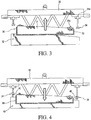
- FIG. 3 shows a side view of a material handling system for processing a laminate comprising alignment features (readable elements).
- a material handling system 30 with a vacuum chuck 31 is placed over a lay-up mandrel 32.
- the placement of the material handling system has typically not been precise due to extraneously motion from sources such as, for example, crane motion, etc.
- the vacuum chuck 31 is evacuated, and the material handling system elevates, breaking the layment 36 away from the lay-up mandrel.
- Vacuum chuck 31 comprises eddy current proximity sensors 33, each mounted on an X-Y digitally-controlled motion guideway 33a perform a raster scan to acquire the position of the alignment features (not shown).
- Automated data analysis provides the precise location of the layment relative to the material handling system based on the precise location of the detected alignment features.
- Registration guides 34, mounted on X-Y digitally-controlled motion guideway 34a are driven to appropriate positions relative to the layment 36.
- FIG. 4 shows a side view of the laminate processing of FIG. 3 moved to a cure mandrel 40.
- the material handling system 30 moves the layment 36 to a cure mandrel 40.
- the registration guides 34 having been driven by computer control to the proper locations, engage tooling balls 42 on the cure mandrel 40.
- FIGs. 5a and 5b are representative raster scans of a laminate comprising the readable feature of the present disclosure.
- FIG. 5a shows a raster scan of a stainless steel washer shaped feature dimensioned at about 3/16" x 1/8" x 0.002" (4.7625 mm x 3.175 mm x 0.0508 mm) under a single layer of prepreg, with the prepreg thickness commonly being about 0.0076" (0.19304 mm).
- FIG. 5a shows a raster scan of a stainless steel washer shaped feature dimensioned at about 3/16" x 1/8" x 0.002" (4.7625 mm x 3.175 mm x 0.0508 mm) under a single layer of prepreg, with the prepreg thickness commonly being about 0.0076" (0.19304 mm).
- 5b shows a 1/8" x 0.002" (3.175 mm x 0.0508 mm) nickel disk under a single layer of prepreg. Both scans may provide satisfactory results for generating accurate position measurement within at least about 0.030" (0.762 mm). In ultrasonic inspection, neither feature presents a large enough signature to be regarded as a flaw; with a flaw defined as being greater than about 0.25" x 0.25" (6.35 mm x 6.35 mm)
- FIG. 6 shows a flow diagram for a lamination process 60, in which a product's digital definition 62 is used to drive the material deposition from a lamination machine 64 and the alignment feature (readable element) placement device 66 responsible for implanting the alignment feature (readable element) into the laminate being fabricated.
- FIG. 7 shows a flow diagram for a preferred lamination placement process 70.
- the desired finished product comprising the laminate has a product digital definition 71.
- Data from definition 71 along with data from the known tool (cure tool in this example calculation) 72 and the sensed alignment feature (readable element) 73 are fed into calculation means 74.
- the values from the calculation means 74 are combined with placement correction offset values 75 and together sent to an actuation control mechanism in a final positioning actuator device 76.
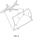
- FIG. 8 discloses how readable elements provide useful navigational monuments for in-service maintenance of airframes.
- an inspection method such as an ultrasonic method, either manual or automated, discovers a feature of interest 82.
- the location is now sufficiently mapped for subsequent recovery of the location for further inspection or repair, for example.
- exemplary method 100 may include specification and design 104 of the aircraft 102 and material procurement 106.
- component and subassembly manufacturing 108 and system integration 110 of the aircraft 102 takes place.
- the aircraft 102 may go through certification and delivery 112 in order to be placed in service 114.
- routine maintenance and service 116 which may also include modification, reconfiguration, refurbishment, and so on).
- a system integrator may include without limitation any number of aircraft manufacturers and major-system subcontractors; a third party may include without limitation any number of venders, subcontractors, and suppliers; and an operator may be an airline, leasing company, military entity, service organization, and so on.
- the aircraft 102 produced by exemplary method 100 may include an airframe 118 with a plurality of systems 120 and an interior 122.
- high-level systems 120 include one or more of a propulsion system 124, an electrical system 126, a hydraulic system 126, and an environmental system 130. Any number of other systems may be included.
- an aerospace example is shown, the principles of the invention may be applied to other industries, such as the automotive industry.
- Apparatus and methods embodied herein may be employed during any one or more of the stages of the production and service method 100.
- components or subassemblies corresponding to production process 108 may be fabricated or manufactured in a manner similar to components or subassemblies produced while the aircraft 102 is in service.
- one or more apparatus embodiments, method embodiments, or a combination thereof may be utilized during the production stages 108 and 110, for example, by substantially expediting assembly of or reducing the cost of an aircraft 102.
- apparatus embodiments, method embodiments, or a combination thereof may be utilized while the aircraft 102 is in service, for example and without limitation, to maintenance and service 116.
- the present disclosure is directed to methods for positively and accurately detecting the location of an implanted, readable element in a laminate to enable a detector to send automated signals to a manual, or preferably automated, operation to provide precise and desired positioning of the laminate for further processing, installation, part identification, etc.
- Further processing contemplates any and all functions such as, for example, adding more layers to the laminate, placement of the laminate on a cure mandrel, locating net trim and holes, dimensional inspection, non-destructive evaluation (NDE) processes (in production and in service), etc.
- NDE non-destructive evaluation
- the readable element is preferably a latent alignment feature implanted into the laminate at various desired and preselected locations as determined and necessitated by the part program.
- the readable element is preferably a small feature of any desired symmetric or asymmetric geometry, such as, for example, a small disk, square, rectangle, ellipse, arrow, etc., and preferably comprising a metal, such as, for example, stainless steel foil.
- the readable element can be detected by any suitable detection means, such as, for example, a proximity sensor able to detect eddy currents, but can also be a sensor in connection with ultrasonic sensors, thermal imaging sensors, x-ray sensors, etc., and combinations thereof.
- the readable element contributes an insignificant impact to the mechanical properties and non-destructive evaluations (NDEs) of the laminate containing the feature.
- NDEs non-destructive evaluations
- the use of such a readable element feature can also provide permanent identification unique to each layment, as well as providing verification of NDE processes such as, for example, providing a known artifact at a known depth.
- the incorporation of the readable features of the present disclosure provides certain, precise and accurate information on the positioning of a part, such as a composite laminate relative to positioning data obtained, thus reducing the presently realized necessary error budget for processes occurring at or downstream from lamination processing stations.
- the readable feature implanted in the laminate was a stainless steel shaped feature having a dimension of about 3/16" x 1/8" (about 4.7625 mm x 3.175 mm), with a thickness of about 0.002" (0.0508 mm) under one layer of prepreg.
- a raster scan imaging of this implanted readable device is shown in FIGs. 5a and 5b . These images shown in FIGs. 5a and 5b would be satisfactory for generating accurate and precise measurement for layment placement within 0.030" (0.762 mm) or better.
- a readable element applicator can be retrofitted as an accessory to any lamination equipment as would be readily understood by one skilled in the laminate field.
- the readable element may be placed manually by use of templates or other placement guides such as, for example, an optical layout template (OLT).
- OLT optical layout template
- the digital definition of the part or product drives the lamination processes as well as the placement of the readable element alignment features.
- sensors from a detector locate the readable element(s) to determine the position, as well as the unique identity of the laminate.
- the data generated are compared to known tool position data to extract laminate placement correction offsets that drive the final positioning actuators.
- the readable elements can provide identifying information by being positioned in preselected locations to produce a predetermined array. In the simplest case, the measured distance between two readable elements is unique, thereby distinguishing one layment from another. An array of several readable elements can generate large numbers of unique combinations of positions and distances.
- still more digital information may be conveyed by giving the readable elements magnetic domains within the element, much like a piece of magnetic recording tape, etc.
- RFID chips may be used to convey a substantial amount of information, as desired.
- Such devices include, but are not limited to, parts designed to be positioned on the exterior or interior of atmospheric and aerospace vehicles and other objects, and structures designed for use in space or other upper-atmosphere environments, such as, for example manned or unmanned vehicles and objects.
- Contemplated objects include, but are not limited to vehicles, such as, for example, aircraft, spacecraft, satellites, rockets, missiles, etc. and therefore include manned and unmanned aircraft, spacecraft, terrestrial, non-terrestrial, and even surface and sub-surface water-borne vehicles and objects.
Landscapes
- Engineering & Computer Science (AREA)
- Chemical & Material Sciences (AREA)
- Composite Materials (AREA)
- Mechanical Engineering (AREA)
- Textile Engineering (AREA)
- Moulding By Coating Moulds (AREA)
- Length Measuring Devices With Unspecified Measuring Means (AREA)
- Analysing Materials By The Use Of Radiation (AREA)
Claims (3)
- Verfahren zum Herstellen eines fertigen Laminats, welches die folgenden Schritte aufweist:Bereitstellen eines Laminatmaterials (21) an eine Laminiermaschine (24);Bereitstellen von mindestens einem lesbaren Element;Einbetten des lesbaren Elements in das Laminatmaterial (21) ;Bereitstellen einer Schichtbildungsmaschine (24), welche einen Detektor für lesbare Elemente aufweist;Bereitstellen des Laminats, welches das lesbare Element aufweist, an die Schichtbildungsmaschine (24),Erfassen des mindestens einen lesbaren Elements und präzises Positionieren des Laminats auf der Schichtbildungsmaschine (21) zum Bilden einer Schicht (25);Entfernen der Schicht (25) von der Schichtbildungsmaschine (24) ;Bereitstellen eines Härtedorns (26), welcher einen Detektor für lesbare Elemente aufweist;Ausrichten der Schicht (25) zum Härtedorn (26);Erfassen des mindestens einen lesbaren Elements und präzises Positionieren der Schicht auf dem Härtedorn (26); undHärten der Schicht (25) zum Herstellen eines fertigen Laminats;wobei das Verfahren ferner das eindeutige Kennzeichnen des Laminats unter Verwendung des lesbaren Elements aufweist, um ein präzises und erwünschtes Positionieren des Laminats zur weiteren Verarbeitung, Montage und Identifizierung von Teilen stromabwärts von den Laminierungsverarbeitungsstationen, bereitzustellen.
- Verfahren nach Anspruch 1, wobei das lesbare Element aus einem Material hergestellt ist, welches aus der Gruppe ausgewählt ist, die aus Folgendem besteht: metallhaltigem Material, metallorganischem Material, radioaktivem Material und Kombinationen davon.
- Verfahren nach Anspruch 1, wobei das lesbare Element von einem Detektor erfasst wird, welcher aus der Gruppe ausgewählt ist, die aus Folgendem besteht: Näherungssensoren, Ultraschallsensoren, Wärmebildsensoren, Röntgensensoren, Wirbelstromsensoren und Kombinationen davon.
Applications Claiming Priority (2)
| Application Number | Priority Date | Filing Date | Title |
|---|---|---|---|
| US13/734,082 US9162436B2 (en) | 2013-01-04 | 2013-01-04 | Method and apparatus for accurate registration of composite laminates |
| PCT/US2013/070594 WO2014107237A1 (en) | 2013-01-04 | 2013-11-18 | Method for accurate registration of composite laminates |
Publications (2)
| Publication Number | Publication Date |
|---|---|
| EP2941341A1 EP2941341A1 (de) | 2015-11-11 |
| EP2941341B1 true EP2941341B1 (de) | 2018-07-04 |
Family
ID=49709844
Family Applications (1)
| Application Number | Title | Priority Date | Filing Date |
|---|---|---|---|
| EP13799454.7A Active EP2941341B1 (de) | 2013-01-04 | 2013-11-18 | Verfahren zur genauen registrierung von verbundlaminaten |
Country Status (6)
| Country | Link |
|---|---|
| US (1) | US9162436B2 (de) |
| EP (1) | EP2941341B1 (de) |
| JP (1) | JP6228611B2 (de) |
| CN (1) | CN104822514B (de) |
| CA (1) | CA2889567C (de) |
| WO (1) | WO2014107237A1 (de) |
Families Citing this family (7)
| Publication number | Priority date | Publication date | Assignee | Title |
|---|---|---|---|---|
| US9370922B1 (en) * | 2014-03-18 | 2016-06-21 | The Boeing Company | Systems and methods for stretch-forming multi-thickness composite skins |
| US10692204B2 (en) | 2016-08-01 | 2020-06-23 | The Boeing Company | System and method for high speed surface and subsurface FOD and defect detection |
| US10041889B2 (en) | 2016-08-01 | 2018-08-07 | The Boeing Company | System and method for high speed surface and subsurface FOD and defect detection |
| FR3061076B1 (fr) * | 2016-12-27 | 2020-02-07 | Safran Nacelles | Procede automatise de reperage pour la fabrication de panneau sandwich de nacelles d'aerostructures |
| WO2020099315A1 (en) * | 2018-11-13 | 2020-05-22 | Lm Wind Power A/S | A detection system, a method and a detection device thereof |
| DE102018133683A1 (de) * | 2018-12-28 | 2020-07-02 | Airbus Operations Gmbh | Gerät und Verfahren zum Positionieren von Materiallagen, insbesondere Fasern, auf einem Formwerkzeug |
| US12099894B2 (en) | 2019-09-20 | 2024-09-24 | Rtx Corporation | Composite material marking and identification |
Family Cites Families (11)
| Publication number | Priority date | Publication date | Assignee | Title |
|---|---|---|---|---|
| EP0472590A4 (en) * | 1989-05-08 | 1992-05-27 | American Composite Technology Inc. | System and method for monitoring pressure during the production of fiber reinforced polymers |
| US5560102A (en) | 1992-10-13 | 1996-10-01 | The Boeing Company | Panel and fuselage assembly |
| US6496745B1 (en) | 2000-05-17 | 2002-12-17 | Lockheed Martin Corporation | Integration of self-locating feature into detail parts |
| US7068170B2 (en) | 2004-03-26 | 2006-06-27 | The Boeing Company | RFID embedded materials |
| US7423523B2 (en) | 2005-08-03 | 2008-09-09 | The Boeing Company | Composite ply layup using electronically identifiable tags |
| US20090208683A1 (en) | 2007-12-06 | 2009-08-20 | Rodman William L | Alignment system and methods for composite assemblies |
| EP2213476A1 (de) * | 2009-01-30 | 2010-08-04 | Spanolux N.V.- DIV. Balterio | Verfahren zur Herstellung einer Laminatplatte, Vorrichtung und Laminatplatte |
| WO2011047167A1 (en) | 2009-10-16 | 2011-04-21 | Gerber Scientific International, Inc. | Methods and systems for manufacturing composite parts |
| US8981285B2 (en) | 2010-09-28 | 2015-03-17 | The Boeing Company | X-ray backscattering part identification and tagging process and technique |
| US8812251B2 (en) * | 2011-04-12 | 2014-08-19 | The Boeing Company | System and method for monitoring bonding integrity |
| US9969131B2 (en) * | 2011-06-22 | 2018-05-15 | The Boeing Company | Automated ply layup system |
-
2013
- 2013-01-04 US US13/734,082 patent/US9162436B2/en active Active
- 2013-11-18 CN CN201380060154.3A patent/CN104822514B/zh active Active
- 2013-11-18 CA CA2889567A patent/CA2889567C/en active Active
- 2013-11-18 WO PCT/US2013/070594 patent/WO2014107237A1/en not_active Ceased
- 2013-11-18 JP JP2015551673A patent/JP6228611B2/ja active Active
- 2013-11-18 EP EP13799454.7A patent/EP2941341B1/de active Active
Non-Patent Citations (1)
| Title |
|---|
| None * |
Also Published As
| Publication number | Publication date |
|---|---|
| CN104822514A (zh) | 2015-08-05 |
| EP2941341A1 (de) | 2015-11-11 |
| US20140193618A1 (en) | 2014-07-10 |
| WO2014107237A1 (en) | 2014-07-10 |
| US9162436B2 (en) | 2015-10-20 |
| CN104822514B (zh) | 2016-10-12 |
| CA2889567A1 (en) | 2014-07-10 |
| JP2016510268A (ja) | 2016-04-07 |
| CA2889567C (en) | 2017-10-24 |
| JP6228611B2 (ja) | 2017-11-08 |
Similar Documents
| Publication | Publication Date | Title |
|---|---|---|
| CA2889567C (en) | Method for accurate registration of composite laminates | |
| US9156240B2 (en) | Automated production and installation of patches for reworking structures | |
| US9034128B2 (en) | Fitting doublers using gap mapping | |
| EP3109622B1 (de) | Automatisches harzgratreduktionssystem | |
| EP1749642B1 (de) | Auflegen von Verbundschichten mit elektronischen Identifikationsetiketten | |
| US8568545B2 (en) | Automated material removal in composite structures | |
| EP2881817B1 (de) | System und Verfahren zum Betreiben einer Maschine und Durchführung der Qualitätssicherung | |
| EP3598123B1 (de) | System und verfahren zur verbundwerkstofffertigung | |
| AU2016200880B2 (en) | Patch fabrication system | |
| JP7060475B2 (ja) | 自動リベット測定システム | |
| US10688697B2 (en) | Apparatus and method of forming a composite structure | |
| US20110089591A1 (en) | Methods and Systems for Manufacturing Composite Parts | |
| KR102558425B1 (ko) | 워크피스 상에서 자동화된 동작들을 수행하기 위한 방법 및 디바이스 | |
| US20190366574A1 (en) | Composite Manufacturing System and Method | |
| US12066819B2 (en) | Printed fiducial system for accurate pick and place | |
| US10239251B2 (en) | Apparatus and method of forming a composite structure | |
| JP7216492B2 (ja) | 磁性材料を有するツール | |
| US8324911B2 (en) | Gap mapping for fitting composite doublers | |
| US12296574B2 (en) | Apparatus and method for processing consolidated stacks of fiber reinforced plies | |
| US20240070837A1 (en) | Natural feature pick and place system for composite materials | |
| US12259362B2 (en) | Non-destructive inspection station for aircraft fuselage sections fabricated in an assembly line | |
| US20250139784A1 (en) | Method and System for Ply Boundary Detection | |
| AU2019203937A1 (en) | Method and system for tuning a tow placement system |
Legal Events
| Date | Code | Title | Description |
|---|---|---|---|
| PUAI | Public reference made under article 153(3) epc to a published international application that has entered the european phase |
Free format text: ORIGINAL CODE: 0009012 |
|
| 17P | Request for examination filed |
Effective date: 20150727 |
|
| AK | Designated contracting states |
Kind code of ref document: A1 Designated state(s): AL AT BE BG CH CY CZ DE DK EE ES FI FR GB GR HR HU IE IS IT LI LT LU LV MC MK MT NL NO PL PT RO RS SE SI SK SM TR |
|
| AX | Request for extension of the european patent |
Extension state: BA ME |
|
| DAX | Request for extension of the european patent (deleted) | ||
| GRAP | Despatch of communication of intention to grant a patent |
Free format text: ORIGINAL CODE: EPIDOSNIGR1 |
|
| STAA | Information on the status of an ep patent application or granted ep patent |
Free format text: STATUS: GRANT OF PATENT IS INTENDED |
|
| INTG | Intention to grant announced |
Effective date: 20180227 |
|
| GRAS | Grant fee paid |
Free format text: ORIGINAL CODE: EPIDOSNIGR3 |
|
| GRAA | (expected) grant |
Free format text: ORIGINAL CODE: 0009210 |
|
| STAA | Information on the status of an ep patent application or granted ep patent |
Free format text: STATUS: THE PATENT HAS BEEN GRANTED |
|
| AK | Designated contracting states |
Kind code of ref document: B1 Designated state(s): AL AT BE BG CH CY CZ DE DK EE ES FI FR GB GR HR HU IE IS IT LI LT LU LV MC MK MT NL NO PL PT RO RS SE SI SK SM TR |
|
| REG | Reference to a national code |
Ref country code: GB Ref legal event code: FG4D |
|
| REG | Reference to a national code |
Ref country code: CH Ref legal event code: EP |
|
| REG | Reference to a national code |
Ref country code: AT Ref legal event code: REF Ref document number: 1014048 Country of ref document: AT Kind code of ref document: T Effective date: 20180715 |
|
| REG | Reference to a national code |
Ref country code: IE Ref legal event code: FG4D |
|
| REG | Reference to a national code |
Ref country code: DE Ref legal event code: R096 Ref document number: 602013039815 Country of ref document: DE |
|
| REG | Reference to a national code |
Ref country code: NL Ref legal event code: MP Effective date: 20180704 |
|
| REG | Reference to a national code |
Ref country code: LT Ref legal event code: MG4D |
|
| REG | Reference to a national code |
Ref country code: AT Ref legal event code: MK05 Ref document number: 1014048 Country of ref document: AT Kind code of ref document: T Effective date: 20180704 |
|
| PG25 | Lapsed in a contracting state [announced via postgrant information from national office to epo] |
Ref country code: NL Free format text: LAPSE BECAUSE OF FAILURE TO SUBMIT A TRANSLATION OF THE DESCRIPTION OR TO PAY THE FEE WITHIN THE PRESCRIBED TIME-LIMIT Effective date: 20180704 |
|
| PG25 | Lapsed in a contracting state [announced via postgrant information from national office to epo] |
Ref country code: LT Free format text: LAPSE BECAUSE OF FAILURE TO SUBMIT A TRANSLATION OF THE DESCRIPTION OR TO PAY THE FEE WITHIN THE PRESCRIBED TIME-LIMIT Effective date: 20180704 Ref country code: RS Free format text: LAPSE BECAUSE OF FAILURE TO SUBMIT A TRANSLATION OF THE DESCRIPTION OR TO PAY THE FEE WITHIN THE PRESCRIBED TIME-LIMIT Effective date: 20180704 Ref country code: AT Free format text: LAPSE BECAUSE OF FAILURE TO SUBMIT A TRANSLATION OF THE DESCRIPTION OR TO PAY THE FEE WITHIN THE PRESCRIBED TIME-LIMIT Effective date: 20180704 Ref country code: NO Free format text: LAPSE BECAUSE OF FAILURE TO SUBMIT A TRANSLATION OF THE DESCRIPTION OR TO PAY THE FEE WITHIN THE PRESCRIBED TIME-LIMIT Effective date: 20181004 Ref country code: IS Free format text: LAPSE BECAUSE OF FAILURE TO SUBMIT A TRANSLATION OF THE DESCRIPTION OR TO PAY THE FEE WITHIN THE PRESCRIBED TIME-LIMIT Effective date: 20181104 Ref country code: PL Free format text: LAPSE BECAUSE OF FAILURE TO SUBMIT A TRANSLATION OF THE DESCRIPTION OR TO PAY THE FEE WITHIN THE PRESCRIBED TIME-LIMIT Effective date: 20180704 Ref country code: CZ Free format text: LAPSE BECAUSE OF FAILURE TO SUBMIT A TRANSLATION OF THE DESCRIPTION OR TO PAY THE FEE WITHIN THE PRESCRIBED TIME-LIMIT Effective date: 20180704 Ref country code: BG Free format text: LAPSE BECAUSE OF FAILURE TO SUBMIT A TRANSLATION OF THE DESCRIPTION OR TO PAY THE FEE WITHIN THE PRESCRIBED TIME-LIMIT Effective date: 20181004 Ref country code: FI Free format text: LAPSE BECAUSE OF FAILURE TO SUBMIT A TRANSLATION OF THE DESCRIPTION OR TO PAY THE FEE WITHIN THE PRESCRIBED TIME-LIMIT Effective date: 20180704 Ref country code: GR Free format text: LAPSE BECAUSE OF FAILURE TO SUBMIT A TRANSLATION OF THE DESCRIPTION OR TO PAY THE FEE WITHIN THE PRESCRIBED TIME-LIMIT Effective date: 20181005 Ref country code: SE Free format text: LAPSE BECAUSE OF FAILURE TO SUBMIT A TRANSLATION OF THE DESCRIPTION OR TO PAY THE FEE WITHIN THE PRESCRIBED TIME-LIMIT Effective date: 20180704 |
|
| PG25 | Lapsed in a contracting state [announced via postgrant information from national office to epo] |
Ref country code: ES Free format text: LAPSE BECAUSE OF FAILURE TO SUBMIT A TRANSLATION OF THE DESCRIPTION OR TO PAY THE FEE WITHIN THE PRESCRIBED TIME-LIMIT Effective date: 20180704 Ref country code: AL Free format text: LAPSE BECAUSE OF FAILURE TO SUBMIT A TRANSLATION OF THE DESCRIPTION OR TO PAY THE FEE WITHIN THE PRESCRIBED TIME-LIMIT Effective date: 20180704 Ref country code: LV Free format text: LAPSE BECAUSE OF FAILURE TO SUBMIT A TRANSLATION OF THE DESCRIPTION OR TO PAY THE FEE WITHIN THE PRESCRIBED TIME-LIMIT Effective date: 20180704 Ref country code: HR Free format text: LAPSE BECAUSE OF FAILURE TO SUBMIT A TRANSLATION OF THE DESCRIPTION OR TO PAY THE FEE WITHIN THE PRESCRIBED TIME-LIMIT Effective date: 20180704 |
|
| REG | Reference to a national code |
Ref country code: DE Ref legal event code: R097 Ref document number: 602013039815 Country of ref document: DE |
|
| PG25 | Lapsed in a contracting state [announced via postgrant information from national office to epo] |
Ref country code: RO Free format text: LAPSE BECAUSE OF FAILURE TO SUBMIT A TRANSLATION OF THE DESCRIPTION OR TO PAY THE FEE WITHIN THE PRESCRIBED TIME-LIMIT Effective date: 20180704 Ref country code: IT Free format text: LAPSE BECAUSE OF FAILURE TO SUBMIT A TRANSLATION OF THE DESCRIPTION OR TO PAY THE FEE WITHIN THE PRESCRIBED TIME-LIMIT Effective date: 20180704 Ref country code: EE Free format text: LAPSE BECAUSE OF FAILURE TO SUBMIT A TRANSLATION OF THE DESCRIPTION OR TO PAY THE FEE WITHIN THE PRESCRIBED TIME-LIMIT Effective date: 20180704 |
|
| PLBE | No opposition filed within time limit |
Free format text: ORIGINAL CODE: 0009261 |
|
| STAA | Information on the status of an ep patent application or granted ep patent |
Free format text: STATUS: NO OPPOSITION FILED WITHIN TIME LIMIT |
|
| PG25 | Lapsed in a contracting state [announced via postgrant information from national office to epo] |
Ref country code: SM Free format text: LAPSE BECAUSE OF FAILURE TO SUBMIT A TRANSLATION OF THE DESCRIPTION OR TO PAY THE FEE WITHIN THE PRESCRIBED TIME-LIMIT Effective date: 20180704 Ref country code: DK Free format text: LAPSE BECAUSE OF FAILURE TO SUBMIT A TRANSLATION OF THE DESCRIPTION OR TO PAY THE FEE WITHIN THE PRESCRIBED TIME-LIMIT Effective date: 20180704 Ref country code: SK Free format text: LAPSE BECAUSE OF FAILURE TO SUBMIT A TRANSLATION OF THE DESCRIPTION OR TO PAY THE FEE WITHIN THE PRESCRIBED TIME-LIMIT Effective date: 20180704 |
|
| 26N | No opposition filed |
Effective date: 20190405 |
|
| REG | Reference to a national code |
Ref country code: CH Ref legal event code: PL |
|
| PG25 | Lapsed in a contracting state [announced via postgrant information from national office to epo] |
Ref country code: LU Free format text: LAPSE BECAUSE OF NON-PAYMENT OF DUE FEES Effective date: 20181118 Ref country code: MC Free format text: LAPSE BECAUSE OF FAILURE TO SUBMIT A TRANSLATION OF THE DESCRIPTION OR TO PAY THE FEE WITHIN THE PRESCRIBED TIME-LIMIT Effective date: 20180704 |
|
| REG | Reference to a national code |
Ref country code: BE Ref legal event code: MM Effective date: 20181130 |
|
| REG | Reference to a national code |
Ref country code: IE Ref legal event code: MM4A |
|
| PG25 | Lapsed in a contracting state [announced via postgrant information from national office to epo] |
Ref country code: CH Free format text: LAPSE BECAUSE OF NON-PAYMENT OF DUE FEES Effective date: 20181130 Ref country code: LI Free format text: LAPSE BECAUSE OF NON-PAYMENT OF DUE FEES Effective date: 20181130 Ref country code: SI Free format text: LAPSE BECAUSE OF FAILURE TO SUBMIT A TRANSLATION OF THE DESCRIPTION OR TO PAY THE FEE WITHIN THE PRESCRIBED TIME-LIMIT Effective date: 20180704 |
|
| PG25 | Lapsed in a contracting state [announced via postgrant information from national office to epo] |
Ref country code: IE Free format text: LAPSE BECAUSE OF NON-PAYMENT OF DUE FEES Effective date: 20181118 |
|
| PG25 | Lapsed in a contracting state [announced via postgrant information from national office to epo] |
Ref country code: BE Free format text: LAPSE BECAUSE OF NON-PAYMENT OF DUE FEES Effective date: 20181130 |
|
| PG25 | Lapsed in a contracting state [announced via postgrant information from national office to epo] |
Ref country code: MT Free format text: LAPSE BECAUSE OF NON-PAYMENT OF DUE FEES Effective date: 20181118 |
|
| PG25 | Lapsed in a contracting state [announced via postgrant information from national office to epo] |
Ref country code: TR Free format text: LAPSE BECAUSE OF FAILURE TO SUBMIT A TRANSLATION OF THE DESCRIPTION OR TO PAY THE FEE WITHIN THE PRESCRIBED TIME-LIMIT Effective date: 20180704 |
|
| PG25 | Lapsed in a contracting state [announced via postgrant information from national office to epo] |
Ref country code: PT Free format text: LAPSE BECAUSE OF FAILURE TO SUBMIT A TRANSLATION OF THE DESCRIPTION OR TO PAY THE FEE WITHIN THE PRESCRIBED TIME-LIMIT Effective date: 20180704 |
|
| PG25 | Lapsed in a contracting state [announced via postgrant information from national office to epo] |
Ref country code: MK Free format text: LAPSE BECAUSE OF NON-PAYMENT OF DUE FEES Effective date: 20180704 Ref country code: CY Free format text: LAPSE BECAUSE OF FAILURE TO SUBMIT A TRANSLATION OF THE DESCRIPTION OR TO PAY THE FEE WITHIN THE PRESCRIBED TIME-LIMIT Effective date: 20180704 Ref country code: HU Free format text: LAPSE BECAUSE OF FAILURE TO SUBMIT A TRANSLATION OF THE DESCRIPTION OR TO PAY THE FEE WITHIN THE PRESCRIBED TIME-LIMIT; INVALID AB INITIO Effective date: 20131118 |
|
| P01 | Opt-out of the competence of the unified patent court (upc) registered |
Effective date: 20230516 |
|
| PGFP | Annual fee paid to national office [announced via postgrant information from national office to epo] |
Ref country code: DE Payment date: 20251128 Year of fee payment: 13 |
|
| PGFP | Annual fee paid to national office [announced via postgrant information from national office to epo] |
Ref country code: GB Payment date: 20251127 Year of fee payment: 13 |
|
| PGFP | Annual fee paid to national office [announced via postgrant information from national office to epo] |
Ref country code: FR Payment date: 20251125 Year of fee payment: 13 |