EP2941153B1 - Juicer arrangements - Google Patents
Juicer arrangements Download PDFInfo
- Publication number
- EP2941153B1 EP2941153B1 EP13815818.3A EP13815818A EP2941153B1 EP 2941153 B1 EP2941153 B1 EP 2941153B1 EP 13815818 A EP13815818 A EP 13815818A EP 2941153 B1 EP2941153 B1 EP 2941153B1
- Authority
- EP
- European Patent Office
- Prior art keywords
- juice
- arrangement according
- appliance
- juicer
- pathway
- Prior art date
- Legal status (The legal status is an assumption and is not a legal conclusion. Google has not performed a legal analysis and makes no representation as to the accuracy of the status listed.)
- Not-in-force
Links
- 235000011389 fruit/vegetable juice Nutrition 0.000 claims description 47
- 239000012530 fluid Substances 0.000 claims description 24
- 238000010438 heat treatment Methods 0.000 claims description 23
- 238000001816 cooling Methods 0.000 claims description 22
- 230000037361 pathway Effects 0.000 claims description 16
- 238000009928 pasteurization Methods 0.000 claims description 11
- 238000000034 method Methods 0.000 claims description 8
- 238000004140 cleaning Methods 0.000 claims description 6
- 230000008569 process Effects 0.000 claims description 6
- 235000013399 edible fruits Nutrition 0.000 claims description 5
- 241000207199 Citrus Species 0.000 claims description 3
- 238000010521 absorption reaction Methods 0.000 claims description 3
- 235000020971 citrus fruits Nutrition 0.000 claims description 3
- 238000007906 compression Methods 0.000 claims description 3
- 230000005611 electricity Effects 0.000 claims description 3
- 238000001704 evaporation Methods 0.000 claims description 3
- 230000008020 evaporation Effects 0.000 claims description 3
- 235000013311 vegetables Nutrition 0.000 claims description 3
- XLYOFNOQVPJJNP-UHFFFAOYSA-N water Substances O XLYOFNOQVPJJNP-UHFFFAOYSA-N 0.000 claims description 3
- 238000004891 communication Methods 0.000 claims description 2
- 238000003825 pressing Methods 0.000 claims description 2
- 230000001419 dependent effect Effects 0.000 claims 1
- 239000000463 material Substances 0.000 description 3
- 238000003860 storage Methods 0.000 description 3
- 238000010586 diagram Methods 0.000 description 2
- 230000000694 effects Effects 0.000 description 2
- 230000002879 macerating effect Effects 0.000 description 2
- 230000008901 benefit Effects 0.000 description 1
- 239000003990 capacitor Substances 0.000 description 1
- 230000008859 change Effects 0.000 description 1
- 238000006243 chemical reaction Methods 0.000 description 1
- 230000001684 chronic effect Effects 0.000 description 1
- 238000000576 coating method Methods 0.000 description 1
- 230000001143 conditioned effect Effects 0.000 description 1
- 238000010411 cooking Methods 0.000 description 1
- 238000005520 cutting process Methods 0.000 description 1
- 230000006866 deterioration Effects 0.000 description 1
- 235000013305 food Nutrition 0.000 description 1
- 235000012055 fruits and vegetables Nutrition 0.000 description 1
- 230000002209 hydrophobic effect Effects 0.000 description 1
- 230000007246 mechanism Effects 0.000 description 1
- 239000012528 membrane Substances 0.000 description 1
- 238000005057 refrigeration Methods 0.000 description 1
- 230000004044 response Effects 0.000 description 1
- 238000007789 sealing Methods 0.000 description 1
- 239000007787 solid Substances 0.000 description 1
- 238000004659 sterilization and disinfection Methods 0.000 description 1
Images



Classifications
-
- A—HUMAN NECESSITIES
- A47—FURNITURE; DOMESTIC ARTICLES OR APPLIANCES; COFFEE MILLS; SPICE MILLS; SUCTION CLEANERS IN GENERAL
- A47J—KITCHEN EQUIPMENT; COFFEE MILLS; SPICE MILLS; APPARATUS FOR MAKING BEVERAGES
- A47J19/00—Household machines for straining foodstuffs; Household implements for mashing or straining foodstuffs
- A47J19/02—Citrus fruit squeezers; Other fruit juice extracting devices
-
- A—HUMAN NECESSITIES
- A23—FOODS OR FOODSTUFFS; TREATMENT THEREOF, NOT COVERED BY OTHER CLASSES
- A23N—MACHINES OR APPARATUS FOR TREATING HARVESTED FRUIT, VEGETABLES OR FLOWER BULBS IN BULK, NOT OTHERWISE PROVIDED FOR; PEELING VEGETABLES OR FRUIT IN BULK; APPARATUS FOR PREPARING ANIMAL FEEDING- STUFFS
- A23N1/00—Machines or apparatus for extracting juice
- A23N1/02—Machines or apparatus for extracting juice combined with disintegrating or cutting
-
- A—HUMAN NECESSITIES
- A23—FOODS OR FOODSTUFFS; TREATMENT THEREOF, NOT COVERED BY OTHER CLASSES
- A23B—PRESERVATION OF FOODS, FOODSTUFFS OR NON-ALCOHOLIC BEVERAGES; CHEMICAL RIPENING OF FRUIT OR VEGETABLES
- A23B2/00—Preservation of foods or foodstuffs, in general
- A23B2/05—Preservation of foods or foodstuffs, in general by heating using irradiation or electric treatment
-
- A—HUMAN NECESSITIES
- A23—FOODS OR FOODSTUFFS; TREATMENT THEREOF, NOT COVERED BY OTHER CLASSES
- A23B—PRESERVATION OF FOODS, FOODSTUFFS OR NON-ALCOHOLIC BEVERAGES; CHEMICAL RIPENING OF FRUIT OR VEGETABLES
- A23B4/00—Preservation of meat, sausages, fish or fish products
- A23B4/005—Preserving by heating
Definitions
- This invention relates to electric juicers, by which is meant electrically powered appliances usable to express juice from fruits and vegetables. It relates especially, though not exclusively, to juicers for use in domestic kitchens, and it relates to all kinds of electrically powered juicers, such as centrifugal juicers, citrus press juicers utilising ribbed, conical reamers and so-called cold-press juicers utilising vertically mounted screws.
- US 2012/0201943 shows a device having a pot with a heated base and a basket having openings for receiving steam for extracting juice from fruit in the basket.
- US 5771791 shows a juice extractor with a juice collector having a heating means for cooking the collected juice.
- the invention aims to address the above-mentioned difficulty and accordingly provides a juicing arrangement comprising an electrically powered juicing appliance arranged to express juice from fruits and/or vegetables, and a treatment unit incorporated into the appliance and having an inlet in fluid communication with an outlet of the juicing appliance arranged to receive the expressed juice, such that the juice is constrained to flow through the unit to an outlet spout arranged to ouput the juice after treatment, the unit including a heating arrangement operable to heat the juice to a predetermined temperature for a selected duration thereby to subject the juice to a pasteurisation or UHT process.
- the invention enables a user to produce treated juice for immediate consumption and/or for storage.
- the electrically powered appliance comprises any of: a centrifugal juicer, a citrus press-type of juicer utilising a ribbed, conical reamer, or a cold-press juicer utilising a vertically mounted pressing screw.
- said treatment means comprises a module securable to and removable from said appliance; said module having means to receive expressed juice from said appliance.
- said module is formed with a meandering tubular pathway for said expressed juice; part at least of said pathway passing adjacent a heating means supported by said appliance.
- a further part of said pathway passes adjacent a cooling means supported by said appliance, and that said first-mentioned and further parts of said pathway are arranged in series, with said juice passing said heating means before passing said cooling means.
- the treatment means further comprises temperature sensing means for sensing the temperature of said juice as it passes said heating means and a diverter valve controlled by the temperature sensing means for routing the juice back to the start of said pathway if the sensed temperature is insufficient to achieve the treatment.
- said module comprises first and second juxtaposed plate members, and that each plate member is formed with an open half-tubular portion of said meandering pathway and adapted such that the plate members are separable.
- the treatment means comprises active means to drive said fluid through said pathway, and said active means is driven by a driver means supported by the appliance.
- said heating arrangement includes any of: thermoelectric heating means incorporating at least one Peltier chip; resistive wire elements; infrared radiators; thick film elements or combinations thereof.
- said cooling means comprises any of: thermoelectric cooling means incorporating at least one Peltier chip; a vapor-compression device; a vapor absorption cycle device; a separate water cooling system; a heat exchanger, or an evaporation system or combinations thereof.
- Figure 1 shows external features of a juicing arrangement in accordance with one embodiment of the invention.
- the arrangement is incorporated into an electrically powered juicing appliance comprising a centrifugal juicer 10 having a main bowl part 12 defining a generally cylindrical working space within which a macerating device, such as a discoidal cutter plate, is rotated at a reasonably high speed to pulp the fruits or vegetables being juiced.
- a macerating device such as a discoidal cutter plate
- the cutter plate incorporates, or is located near, the base of a frusto-conical filter member the side wall which is pierced, or otherwise formed, with small holes and/or narrow slits, thus being sufficiently porous to permit juice to pass therethrough.
- the cutter plate, and usually also the filter member are spun sufficiently rapidly to separate the juice from pulp residues, comprising mainly fibrous bulk matter. The juice passes through the apertures in the side wall for collection and dispensing whilst the pulp residues are blocked by the filter member and generally thrown upwardly and outwardly therefrom into a pulp-collection chamber 14.
- the main bowl part 12 is capped by a lid 16, through the top of which passes a feed-chute 18 designed to receive and accommodate produce to be juiced, and a pusher (not shown) is provided whereby the produce can be urged through the feed-chute 18 and into abrasive contact with the cutter plate.
- An electric motor used to spin the macerating plate, and usually also the filter member, rapidly within the working space is housed in a main body, or base housing 20, which also supports, in conventional fashion, controls and actuators such as 22 for the motor and ancillary electronics.
- the main body part 20 is configured to house a juice treatment unit 24 which is set up to subject juice expressed from the input produce by the centrifugal juicer 10 to a pasteurisation process.
- the treatment unit 24 could be set up, if preferred, to implement a UHT process.
- the expressed and treated juice is dispensed from the appliance by way of an outlet spout 26 which can advantageously be provided with an anti-dripping mechanism such as that described in WO 2010/128274 A .
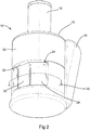
- Figure 2 shows another view of the juicer shown in Figure 1 , but with the juice treatment unit 24 removed, leaving visible the external surface of a heating pad 28 and showing the location of an adjacent cooling means 30. It is desirable for the treatment unit 24 to be removable for cleaning, as will be described in more detail later, and so, in this example, the main body of the appliance 10 is formed with a recess 32 dimensioned and configured to receive and accommodate the unit 24 as a plug-in module, and to retain the unit 24 securely in place during use. Visible at the top of the recess 32 is an aperture 34 which is the exit hole through which juice expressed by the juicer 10 exits the juicer proper and enters the treatment unit 24.
- Figure 3 shows a cross-section through the juicer 10 at about the level of the dashed line III marked in Figures 1 and 2 .
- the recess 32 in the main body part 20 presents outwardly facing surfaces of the heating pad 28 and the cooling means 30.
- the heating and cooling agencies are chosen to comprise thermoelectric heating and refrigeration units incorporating respective Peltier chips (not specifically shown) though the heating and cooling agencies can, if preferred, take any of a number of alternative forms such as (for heating): resistive wire elements, infrared radiators, thick film elements etc. and (for cooling): vapor-compression devices, vapor absorption cycle devices, separate water cooling systems, heat exchangers, or evaporation systems.
- Both the heating pad 28 and cooling means 30 can be powered by any electrical source, such as mains electricity (240/110 volt), battery power, solar power, super capacitors etc., or both or either can utilise endothermic or exothermic chemical reactions.
- any electrical source such as mains electricity (240/110 volt), battery power, solar power, super capacitors etc., or both or either can utilise endothermic or exothermic chemical reactions.
- respective heat sinks 36, 38 are associated with the heater 28 and the cooler 30, and at least the heat sink 38 is provided with forced cooling air by way of a fan 40. Also visible in Figure 3 are a valve driver 42 and a motor drive unit 44, both of which interact with respective components of the treatment unit 24 in a manner now to be described.
- the unit 24 comprises a module which is made of two main parts, comprising a back plate 46 and a front plate 48. These two parts are separable to allow access to their internal components for cleaning, and they may thus be completely separate from one another, or joined together by a hinge or other articulation method so that they can be opened out. These two parts may be made from any suitable material.
- Moulded or otherwise incorporated into both the back plate 46 and the front plate 48 are a series of open channel parts which, when the plates 46 and 48 are assembled together to form the unit 24, combine to form a meandering set of closed fluid channels 50 through which the expressed juice is constrained to flow.
- the channels 50 comprise a heated channel set 52 and a cooled channel set 54 linked together in series.
- the plates 46 and 48 are fitted with sealing components, such as gaskets, and moreover the channels 50 may optionally incorporate hydrophilic or hydrophobic coatings or materials to ease cleaning.
- the fluid travels from a fluid entry hole, at location 56 (aligning with the outlet hole 34 at the top of recess 32 in the appliance 10) into the heated channel set 52 via a pump comprising an impeller 58 which is driven by the aforementioned driver unit 44.
- a temperature sensor 60 Located towards the end of the meandering path formed by the heated channel set 52, there is a temperature sensor 60, which is followed by a diverter valve 62 arranged so that, if the fluid temperature, as sensed by the temperature sensor 60 is not at the specified level, the fluid is diverted back to the beginning of the heated channel set 52, via a bypass channel 64.
- the valve 62 is conditioned to divert the fluid into the cooled channel set 54 and finally through the outlet spout 26 into a receptacle or additional storage chamber.
- the pump 44, 58 can be of any known type such as diaphragm, rotary vane or impeller, and can be operated by any means or power source.
- the impeller 58 is driven directly by a shaft (not shown) from the motor drive unit 44 inside the main body 20 of the juicer 10. This configuration requires no motor on the pasteurisation unit 24, which can thus be removed from the appliance 10 and placed in a dishwasher, or otherwise cleaned.
- the pump can be mounted anywhere in the fluid path and more than one pump can be used if needed.
- a filter may optionally be provided at any convenient location to prevent solid parts of the fruit from entering or travelling through the fluid transfer channels.
- the diverter valve 62 can be of any known type and can be operated by any convenient means or power source.
- the valve 62 is operated directly by a shaft (not shown) that interfaces with the valve drive unit 42 inside the main body 20 of the juicer 10.
- this configuration is advantageous in requiring no active drive components on the pasteurisation unit 24, so enabling it to be removed from the appliance 10 and cleaned, in a dishwasher or otherwise.
- the valve 62 can be operated by a bimetallic strip or other heat activated material that is designed to undergo a physical change at the required temperature.
- the temperature sensor 60 can also be supported within the main body 20 of the juicer 10 and disposed so as to contact the fluid inside the pasteurisation unit 24 via a rubber membrane or a thin wall section in the back plate 46. Moreover, there may be more than one temperature sensor in the fluid path.
- pasteurisation unit 24 is configured as a module which is removable and can be opened to allow cleaning, possibly in a dishwasher, and as the juice moves directly from the working space in the main bowl part 12 into the pasteurisation unit 24, there are minimal additional components to clean and there is no requirement to wash through any pipes in the actual main body 20 of the juicer 10. This is a significant benefit associated with the use of the present invention.
- the currently preferred treatment process is pasteurisation, but UHT treatment can be used instead if preferred.
- the fluid must be heated to roughly 70 degrees centigrade for a period not less than 15 seconds.
- the fluid must be heated to roughly 135 degrees centigrade for a period not less than 0.5 seconds, though these times and temperatures can vary for different foods or fluids.
- the temperatures and times employed by the unit 24 can thus be user defined, preset by the manufacturer or automatically controlled in response to sensed parameters.
- the output temperature of the fluid at the outlet 26 can likewise be preset, user adjustable or automatically adjusted in relation to the ambient temperature via an external temperature sensor. All of the temperature sensors, motors, and valves can be monitored and controlled by a microcontroller which can vary the flow rate of the fluid via the pump speed, the temperature of the fluid at different stages with both the heating and cooling elements 28, 30 and the direction the fluid takes via the position of the valve 62.
- the juicing appliance comprises, in combination, a juicer, such as a centrifugal juicer, and a dedicated carafe or other vessel directly associated with the juicer and configured to receive juice directly expressed from the juicer.
- a juicer such as a centrifugal juicer
- a dedicated carafe or other vessel directly associated with the juicer and configured to receive juice directly expressed from the juicer.
- a treatment means of the form described above is incorporated into the carafe or other vessel, instead of being incorporated into the juicer.
- a treatment means of the form described above is incorporated into the carafe or other vessel, instead of being incorporated into the juicer.
- One example of such an embodiment of the invention provides a matched juicer and carafe mounted on a common base which is connectable to mains electricity and from which the juicer picks up its operating power and the carafe or other vessel picks up power to operate the treatment means.
Landscapes
- Engineering & Computer Science (AREA)
- Food Science & Technology (AREA)
- Life Sciences & Earth Sciences (AREA)
- Chemical & Material Sciences (AREA)
- Polymers & Plastics (AREA)
- Wood Science & Technology (AREA)
- Zoology (AREA)
- Food-Manufacturing Devices (AREA)
- Devices For Dispensing Beverages (AREA)
- Apparatuses For Bulk Treatment Of Fruits And Vegetables And Apparatuses For Preparing Feeds (AREA)
Description
- This invention relates to electric juicers, by which is meant electrically powered appliances usable to express juice from fruits and vegetables. It relates especially, though not exclusively, to juicers for use in domestic kitchens, and it relates to all kinds of electrically powered juicers, such as centrifugal juicers, citrus press juicers utilising ribbed, conical reamers and so-called cold-press juicers utilising vertically mounted screws.
- With the present and on-going interest in healthy nourishment, electric juicers of all kinds have become popular and, in general, they work quite well. However, existing juicers of all kinds share a chronic difficulty in that, because the quality of the expressed juice deteriorates quite rapidly, it is necessary to express relatively small amounts at a time. There is thus, in effect, a limitation to juicing on demand, which carries with it the need to set up, use and clean out the juicer each time juice is required. Centrifugal juicers suffer particularly in this respect, since the juicing operation employed in such appliances exacerbates the deterioration process, by incorporating significant amounts of air into the juice.
-
US 2012/0201943 shows a device having a pot with a heated base and a basket having openings for receiving steam for extracting juice from fruit in the basket.US 5771791 shows a juice extractor with a juice collector having a heating means for cooking the collected juice. - The invention aims to address the above-mentioned difficulty and accordingly provides a juicing arrangement comprising an electrically powered juicing appliance arranged to express juice from fruits and/or vegetables, and a treatment unit incorporated into the appliance and having an inlet in fluid communication with an outlet of the juicing appliance arranged to receive the expressed juice, such that the juice is constrained to flow through the unit to an outlet spout arranged to ouput the juice after treatment, the unit including a heating arrangement operable to heat the juice to a predetermined temperature for a selected duration thereby to subject the juice to a pasteurisation or UHT process.
- By this means, the lifetime of the juice is considerably extended, subject to proper storage conditions being met, so that juice can be prepared in larger volumes than previously, thus negating the requirement for juicing on demand. This naturally reduces the work necessary to set up, operate and clean out the juicer by cutting down on the number of juicing operations needed to prepare a given quantity of juice.
- Moreover, the invention enables a user to produce treated juice for immediate consumption and/or for storage.
- Typically, the electrically powered appliance comprises any of: a centrifugal juicer, a citrus press-type of juicer utilising a ribbed, conical reamer, or a cold-press juicer utilising a vertically mounted pressing screw.
- In some preferred embodiments of the invention, said treatment means comprises a module securable to and removable from said appliance; said module having means to receive expressed juice from said appliance.
- In such embodiments, it is preferred that said module is formed with a meandering tubular pathway for said expressed juice; part at least of said pathway passing adjacent a heating means supported by said appliance.
- It is further preferred that a further part of said pathway passes adjacent a cooling means supported by said appliance, and that said first-mentioned and further parts of said pathway are arranged in series, with said juice passing said heating means before passing said cooling means.
- In particularly preferred embodiments of the invention, the treatment means further comprises temperature sensing means for sensing the temperature of said juice as it passes said heating means and a diverter valve controlled by the temperature sensing means for routing the juice back to the start of said pathway if the sensed temperature is insufficient to achieve the treatment.
- In order to facilitate cleaning of said pathway, it is preferable that said module comprises first and second juxtaposed plate members, and that each plate member is formed with an open half-tubular portion of said meandering pathway and adapted such that the plate members are separable.
- Preferably, the treatment means comprises active means to drive said fluid through said pathway, and said active means is driven by a driver means supported by the appliance.
- Typically, said heating arrangement includes any of: thermoelectric heating means incorporating at least one Peltier chip; resistive wire elements; infrared radiators; thick film elements or combinations thereof.
- Typically, said cooling means (where provided) comprises any of: thermoelectric cooling means incorporating at least one Peltier chip; a vapor-compression device; a vapor absorption cycle device; a separate water cooling system; a heat exchanger, or an evaporation system or combinations thereof.
- In order that the invention may be clearly understood and readily carried into effect, one embodiment thereof will now be described, by way of example only, with reference to the accompanying drawings, of which:
-
Figure 1 shows a general isometric external view of a juicing arrangement according to one example of the invention; showing a treatment module in place; -
Figure 2 is similar toFigure 1 , but shows the arrangement from a different angle and with the treatment module removed; -
Figure 3 shows a cross-sectional view taken on the line III ---- III shown inFigures 1 and2 ; -
Figure 4 shows a cross-section through a treatment module; -
Figure 5 shows the treatment module in front elevation; and -
Figures 6(a), 6(b) and 6(c) show schematic juice-flow diagrams indicative of flow arrangements of differing complexity. -
Figure 1 shows external features of a juicing arrangement in accordance with one embodiment of the invention. - In this example, the arrangement is incorporated into an electrically powered juicing appliance comprising a
centrifugal juicer 10 having amain bowl part 12 defining a generally cylindrical working space within which a macerating device, such as a discoidal cutter plate, is rotated at a reasonably high speed to pulp the fruits or vegetables being juiced. Typically, the cutter plate incorporates, or is located near, the base of a frusto-conical filter member the side wall which is pierced, or otherwise formed, with small holes and/or narrow slits, thus being sufficiently porous to permit juice to pass therethrough. The cutter plate, and usually also the filter member, are spun sufficiently rapidly to separate the juice from pulp residues, comprising mainly fibrous bulk matter. The juice passes through the apertures in the side wall for collection and dispensing whilst the pulp residues are blocked by the filter member and generally thrown upwardly and outwardly therefrom into a pulp-collection chamber 14. - The
main bowl part 12 is capped by alid 16, through the top of which passes a feed-chute 18 designed to receive and accommodate produce to be juiced, and a pusher (not shown) is provided whereby the produce can be urged through the feed-chute 18 and into abrasive contact with the cutter plate. - An electric motor used to spin the macerating plate, and usually also the filter member, rapidly within the working space is housed in a main body, or
base housing 20, which also supports, in conventional fashion, controls and actuators such as 22 for the motor and ancillary electronics. - In this example of the invention, the
main body part 20 is configured to house ajuice treatment unit 24 which is set up to subject juice expressed from the input produce by thecentrifugal juicer 10 to a pasteurisation process. As previously mentioned, however, thetreatment unit 24 could be set up, if preferred, to implement a UHT process. In any event, the expressed and treated juice is dispensed from the appliance by way of anoutlet spout 26 which can advantageously be provided with an anti-dripping mechanism such as that described inWO 2010/128274 A . -
Figure 2 shows another view of the juicer shown inFigure 1 , but with thejuice treatment unit 24 removed, leaving visible the external surface of aheating pad 28 and showing the location of an adjacent cooling means 30. It is desirable for thetreatment unit 24 to be removable for cleaning, as will be described in more detail later, and so, in this example, the main body of theappliance 10 is formed with arecess 32 dimensioned and configured to receive and accommodate theunit 24 as a plug-in module, and to retain theunit 24 securely in place during use. Visible at the top of therecess 32 is anaperture 34 which is the exit hole through which juice expressed by thejuicer 10 exits the juicer proper and enters thetreatment unit 24. -
Figure 3 shows a cross-section through thejuicer 10 at about the level of the dashed line III marked inFigures 1 and2 . Here it can be seen that the recess 32 in themain body part 20 presents outwardly facing surfaces of theheating pad 28 and the cooling means 30. In the present example, the heating and cooling agencies are chosen to comprise thermoelectric heating and refrigeration units incorporating respective Peltier chips (not specifically shown) though the heating and cooling agencies can, if preferred, take any of a number of alternative forms such as (for heating): resistive wire elements, infrared radiators, thick film elements etc. and (for cooling): vapor-compression devices, vapor absorption cycle devices, separate water cooling systems, heat exchangers, or evaporation systems. - In some instances, moreover, combinations of different heating and/or cooling techniques can be used for either agency.
- Both the
heating pad 28 and cooling means 30 can be powered by any electrical source, such as mains electricity (240/110 volt), battery power, solar power, super capacitors etc., or both or either can utilise endothermic or exothermic chemical reactions. - In this example,
respective heat sinks heater 28 and thecooler 30, and at least theheat sink 38 is provided with forced cooling air by way of afan 40. Also visible inFigure 3 are avalve driver 42 and amotor drive unit 44, both of which interact with respective components of thetreatment unit 24 in a manner now to be described. - Referring now to
Figures 4 and 5 , these show thetreatment unit 24 in cross-section and from front elevation respectively. - In this example, the
unit 24 comprises a module which is made of two main parts, comprising aback plate 46 and afront plate 48. These two parts are separable to allow access to their internal components for cleaning, and they may thus be completely separate from one another, or joined together by a hinge or other articulation method so that they can be opened out. These two parts may be made from any suitable material. - Moulded or otherwise incorporated into both the
back plate 46 and thefront plate 48 are a series of open channel parts which, when theplates unit 24, combine to form a meandering set of closedfluid channels 50 through which the expressed juice is constrained to flow. In this example, thechannels 50 comprise a heated channel set 52 and a cooled channel set 54 linked together in series. Theplates channels 50 may optionally incorporate hydrophilic or hydrophobic coatings or materials to ease cleaning. - The fluid travels from a fluid entry hole, at location 56 (aligning with the
outlet hole 34 at the top ofrecess 32 in the appliance 10) into the heated channel set 52 via a pump comprising animpeller 58 which is driven by theaforementioned driver unit 44. Located towards the end of the meandering path formed by the heated channel set 52, there is atemperature sensor 60, which is followed by adiverter valve 62 arranged so that, if the fluid temperature, as sensed by thetemperature sensor 60 is not at the specified level, the fluid is diverted back to the beginning of theheated channel set 52, via abypass channel 64. If, on the other hand, thetemperature sensor 60 determines that the fluid temperature has reached an acceptable level, thevalve 62 is conditioned to divert the fluid into the cooled channel set 54 and finally through theoutlet spout 26 into a receptacle or additional storage chamber. - The
pump impeller 58 is driven directly by a shaft (not shown) from themotor drive unit 44 inside themain body 20 of thejuicer 10. This configuration requires no motor on thepasteurisation unit 24, which can thus be removed from theappliance 10 and placed in a dishwasher, or otherwise cleaned. The pump can be mounted anywhere in the fluid path and more than one pump can be used if needed. A filter (not shown) may optionally be provided at any convenient location to prevent solid parts of the fruit from entering or travelling through the fluid transfer channels. - The
diverter valve 62 can be of any known type and can be operated by any convenient means or power source. In the present example thevalve 62 is operated directly by a shaft (not shown) that interfaces with thevalve drive unit 42 inside themain body 20 of thejuicer 10. As with the impeller drive mentioned previously, this configuration is advantageous in requiring no active drive components on thepasteurisation unit 24, so enabling it to be removed from theappliance 10 and cleaned, in a dishwasher or otherwise. If desired, thevalve 62 can be operated by a bimetallic strip or other heat activated material that is designed to undergo a physical change at the required temperature. - The
temperature sensor 60 can also be supported within themain body 20 of thejuicer 10 and disposed so as to contact the fluid inside thepasteurisation unit 24 via a rubber membrane or a thin wall section in theback plate 46. Moreover, there may be more than one temperature sensor in the fluid path. - As the
pasteurisation unit 24 is configured as a module which is removable and can be opened to allow cleaning, possibly in a dishwasher, and as the juice moves directly from the working space in themain bowl part 12 into thepasteurisation unit 24, there are minimal additional components to clean and there is no requirement to wash through any pipes in the actualmain body 20 of thejuicer 10. This is a significant benefit associated with the use of the present invention. - Referring now to the flow diagrams shown in
Figure 6 , it will be appreciated that various options are available for defining the route to be taken by the expressed fluid through thepasteurisation unit 24. The route just described, utilising a diverter valve arrangement, is represented inFigure 6(b) . A simpler option, shown inFigure 6(a) , does not employ a temperature sensor or diverter valve, and a more complex option, shown inFigure 6(c) incorporates a heat exchanger and thus exhibits improved energy efficiency. In any of the options, a separate holding chamber or channel may be provided between the heating and cooling chambers to hold the warm fluid for a chosen length of time before cooling. - The currently preferred treatment process is pasteurisation, but UHT treatment can be used instead if preferred. To ensure complete pasteurisation, the fluid must be heated to roughly 70 degrees centigrade for a period not less than 15 seconds. To ensure complete UHT sterilisation the fluid must be heated to roughly 135 degrees centigrade for a period not less than 0.5 seconds, though these times and temperatures can vary for different foods or fluids. The temperatures and times employed by the
unit 24 can thus be user defined, preset by the manufacturer or automatically controlled in response to sensed parameters. - The output temperature of the fluid at the
outlet 26 can likewise be preset, user adjustable or automatically adjusted in relation to the ambient temperature via an external temperature sensor. All of the temperature sensors, motors, and valves can be monitored and controlled by a microcontroller which can vary the flow rate of the fluid via the pump speed, the temperature of the fluid at different stages with both the heating andcooling elements valve 62. - In some embodiments of the invention, the juicing appliance comprises, in combination, a juicer, such as a centrifugal juicer, and a dedicated carafe or other vessel directly associated with the juicer and configured to receive juice directly expressed from the juicer.
- In some such embodiments, a treatment means of the form described above is incorporated into the carafe or other vessel, instead of being incorporated into the juicer. One example of such an embodiment of the invention provides a matched juicer and carafe mounted on a common base which is connectable to mains electricity and from which the juicer picks up its operating power and the carafe or other vessel picks up power to operate the treatment means.
Claims (15)
- A juicing arrangement comprising an electrically powered juicing appliance (10) arranged to express juice from fruits and/or vegetables, and a treatment unit (24) incorporated into the appliance and having an inlet (56) in fluid communication with the juicing appliance arranged to receive the expressed juice, such that the juice is constrained to flow through the unit to an outlet spout (26) arranged to output the juice after treatment, the unit (24) including a heating arrangement (28) operable to heat the juice to a predetermined temperature for a selected duration thereby to subject the juice to a pasteurisation or UHT process.
- An arrangement according to claim 1, wherein the electrically powered appliance (10) comprises one of: a centrifugal juicer, a citrus press-type of juicer utilising a ribbed, conical reamer, or a cold-press juicer utilising a vertically mounted pressing screw arranged to express the juice.
- An arrangement according to claim 1 or claim 2, wherein said treatment unit(24) comprises a module securable to and removable from said appliance (10); said module having means (56) to receive expressed juice from said appliance.
- An arrangement according to claim 3 wherein said module (24) is formed with a meandering tubular pathway (50) for said expressed juice; part at least of said pathway (52) passing adjacent the heating arrangement (28) supported by said appliance.
- An arrangement according to claim 4, wherein a further part (54) of said pathway (50) passes adjacent a cooling means (30) supported by said appliance (10).
- An arrangement according to claim 5, wherein said first-mentioned (52) and further (54) parts of said pathway (50) are arranged in series, with said juice passing said heating means (28) before passing said cooling means (30).
- An arrangement according to claim 6, further comprising temperature sensing means (60) for sensing the temperature of said juice as it passes said heating means (28) and a diverter valve (62) controlled by the temperature sensing means for routing the juice back to the start of said pathway (50) if the sensed temperature is insufficient to achieve the treatment.
- An arrangement according to any one of claims 4 to 7, wherein said module (24) comprises first and second juxtaposed plate members (46, 48), and wherein each said plate member is formed with an open half-tubular portion of said meandering pathway (50) and adapted such that the plate members (46, 48) are separable to permit cleaning of said pathway.
- An arrangement according to any one of claims 4 to 8, wherein said treatment means (24) comprises active means (58) to drive said fluid through said pathway (50).
- An arrangement according to claim 9, wherein said active means (58) is driven by a driver means (44) supported by the appliance.
- An arrangement according to any preceding claim, wherein said heating arrangement (28) includes any of: thermoelectric heating means incorporating at least one Peltier chip; resistive wire elements; infrared radiators; thick film elements or combinations thereof.
- An arrangement according to claim 5 or any claim dependent thereon, wherein said cooling means (30) comprises any of: thermoelectric cooling means incorporating at least one Peltier chip; a vapor-compression device; a vapor absorption cycle device; a separate water cooling system; a heat exchanger, or an evaporation system or combinations thereof.
- An arrangement according to any preceding claim, wherein said appliance comprises, in combination, a juicer and a dedicated carafe or other vessel directly associated with the juicer and configured to receive juice directly expressed from the juicer.
- An arrangement according to claim 13, wherein said treatment means (24) is incorporated into the carafe or other vessel.
- An arrangement according to claim 14, wherein said juicer and said carafe or other vessel are mounted on a common base, connectable to mains electricity, from which the juicer picks up its operating power and from which the carafe or other vessel picks up power to operate the treatment means (24).
Applications Claiming Priority (2)
| Application Number | Priority Date | Filing Date | Title |
|---|---|---|---|
| GB1300092.2A GB2509506B (en) | 2013-01-04 | 2013-01-04 | Juicer Arrangements |
| PCT/GB2013/053413 WO2014106737A1 (en) | 2013-01-04 | 2013-12-23 | Juicer arrangements |
Publications (2)
| Publication Number | Publication Date |
|---|---|
| EP2941153A1 EP2941153A1 (en) | 2015-11-11 |
| EP2941153B1 true EP2941153B1 (en) | 2019-04-17 |
Family
ID=47747942
Family Applications (1)
| Application Number | Title | Priority Date | Filing Date |
|---|---|---|---|
| EP13815818.3A Not-in-force EP2941153B1 (en) | 2013-01-04 | 2013-12-23 | Juicer arrangements |
Country Status (6)
| Country | Link |
|---|---|
| US (1) | US9943099B2 (en) |
| EP (1) | EP2941153B1 (en) |
| CN (1) | CN104918525B (en) |
| BR (1) | BR112015016095A2 (en) |
| GB (1) | GB2509506B (en) |
| WO (1) | WO2014106737A1 (en) |
Families Citing this family (4)
| Publication number | Priority date | Publication date | Assignee | Title |
|---|---|---|---|---|
| GB2546507B (en) * | 2016-01-19 | 2022-03-02 | Kenwood Ltd | Food processing hub |
| WO2020233876A1 (en) * | 2019-05-21 | 2020-11-26 | Arcelik Anonim Sirketi | A fruit and vegetable juicer |
| USD1027575S1 (en) * | 2019-08-06 | 2024-05-21 | Breville Pty Limited | Blender |
| USD1027576S1 (en) | 2020-03-18 | 2024-05-21 | Capbran Holdings, Llc | Juicer |
Citations (4)
| Publication number | Priority date | Publication date | Assignee | Title |
|---|---|---|---|---|
| US5771791A (en) * | 1997-09-01 | 1998-06-30 | Ling; Kuo-I | Multipurpose juice extractor |
| WO2002034059A1 (en) * | 2000-10-23 | 2002-05-02 | Alejandro Mendez | Apparatus and method of aseptic packaging perishables |
| CN101223963A (en) * | 2007-01-17 | 2008-07-23 | 宋大伟 | Flesh and fruit paste machine |
| US20120201943A1 (en) * | 2011-02-07 | 2012-08-09 | Schloer Simon | Multipurpose sterilization and juice extraction device |
Family Cites Families (19)
| Publication number | Priority date | Publication date | Assignee | Title |
|---|---|---|---|---|
| JPH02163066A (en) | 1988-12-15 | 1990-06-22 | Kazuo Yamamoto | Production of opaque fruit juice |
| CN2189433Y (en) * | 1993-12-30 | 1995-02-15 | 刘建刚 | Automatic bean-milk-making machine |
| KR100217515B1 (en) * | 1994-09-30 | 1999-09-01 | 오타 유다카 | Laminated heat exchanger tube and manufactuing method therefor |
| US6371013B1 (en) * | 2001-08-02 | 2002-04-16 | Tsann Kuen Usa Inc. | Fruit squeezer with an additive adding mechanism |
| US20030075057A1 (en) * | 2001-10-04 | 2003-04-24 | Craig Saunders | Apparatus for making sweetened beverages |
| CN1218668C (en) * | 2002-01-07 | 2005-09-14 | 孙学义 | Movable processing equipment for fresh fruit and vegetable juice |
| WO2006002384A1 (en) * | 2004-06-24 | 2006-01-05 | Select-Measure Consumption, L.L.C. | Metered volume liquid dispensing device |
| US9016196B2 (en) * | 2005-06-03 | 2015-04-28 | Breville Pty Limited | Compact juicer |
| JP2007101088A (en) * | 2005-10-05 | 2007-04-19 | Calsonic Kansei Corp | Tank structure for heat exchanger |
| CN2868137Y (en) * | 2005-12-11 | 2007-02-14 | 胡秋雷 | Food processing machine with bottom-free net |
| JP5058559B2 (en) * | 2006-01-24 | 2012-10-24 | サンデン株式会社 | Beverage extractor |
| CN201150445Y (en) * | 2008-01-02 | 2008-11-19 | 厦门灿坤实业股份有限公司 | A fruit juice machine with heating function |
| CN201205192Y (en) * | 2008-04-19 | 2009-03-11 | 顾永洪 | Multifunctional automatic juicer |
| FR2939296B1 (en) * | 2008-12-10 | 2013-07-05 | Seb Sa | HOUSEHOLD APPLIANCE FOR PREPARING SOYBEAN MILK. |
| DE102009006672A1 (en) | 2009-01-29 | 2010-08-05 | Vorwerk & Co. Interholding Gmbh | Electromotive operated kitchen machine has stirrer pot, agitator and safety cover with filling or monitoring opening, where agitator is propelled over drive shaft |
| GB2477944B (en) * | 2010-02-18 | 2015-04-01 | Otter Controls Ltd | Cordless electrical appliances |
| CN102240153A (en) * | 2010-05-16 | 2011-11-16 | 马赛香 | Bast fruit juicer |
| CN202077206U (en) | 2011-06-11 | 2011-12-14 | 邵博言 | Heating disc of juicer |
| CN102273511A (en) * | 2011-08-12 | 2011-12-14 | 九阳股份有限公司 | Process for rapidly preparing soybean milk |
-
2013
- 2013-01-04 GB GB1300092.2A patent/GB2509506B/en not_active Expired - Fee Related
- 2013-12-23 EP EP13815818.3A patent/EP2941153B1/en not_active Not-in-force
- 2013-12-23 BR BR112015016095A patent/BR112015016095A2/en not_active Application Discontinuation
- 2013-12-23 CN CN201380069348.XA patent/CN104918525B/en not_active Expired - Fee Related
- 2013-12-23 US US14/759,123 patent/US9943099B2/en active Active
- 2013-12-23 WO PCT/GB2013/053413 patent/WO2014106737A1/en not_active Ceased
Patent Citations (4)
| Publication number | Priority date | Publication date | Assignee | Title |
|---|---|---|---|---|
| US5771791A (en) * | 1997-09-01 | 1998-06-30 | Ling; Kuo-I | Multipurpose juice extractor |
| WO2002034059A1 (en) * | 2000-10-23 | 2002-05-02 | Alejandro Mendez | Apparatus and method of aseptic packaging perishables |
| CN101223963A (en) * | 2007-01-17 | 2008-07-23 | 宋大伟 | Flesh and fruit paste machine |
| US20120201943A1 (en) * | 2011-02-07 | 2012-08-09 | Schloer Simon | Multipurpose sterilization and juice extraction device |
Also Published As
| Publication number | Publication date |
|---|---|
| GB2509506B (en) | 2016-05-11 |
| BR112015016095A2 (en) | 2017-07-11 |
| EP2941153A1 (en) | 2015-11-11 |
| WO2014106737A1 (en) | 2014-07-10 |
| GB201300092D0 (en) | 2013-02-20 |
| GB2509506A (en) | 2014-07-09 |
| US9943099B2 (en) | 2018-04-17 |
| US20150335059A1 (en) | 2015-11-26 |
| CN104918525A (en) | 2015-09-16 |
| CN104918525B (en) | 2018-03-23 |
Similar Documents
| Publication | Publication Date | Title |
|---|---|---|
| CA3005187C (en) | Coldwave appliance | |
| US8826805B2 (en) | Cooking appliance | |
| US5724883A (en) | Hot/cold beverage brewing device | |
| US6267046B1 (en) | Convection steamer | |
| US9943099B2 (en) | Juicer arrangements | |
| CA2719128A1 (en) | Method of producing a drink, and drinks-preparing device for implementing the method | |
| ES2344331T3 (en) | STEAM FUNCTION AT THE END OF AN INFUSION PROCESS. | |
| JP2013544601A (en) | Simple user interface for beverage machines | |
| CN102245068A (en) | Electrical appliance for preparing and cooking soy milk, juice, or coulis | |
| US20190274472A1 (en) | Modular foaming unit | |
| KR101736220B1 (en) | Multifunctional extracting apparatus for house hold | |
| JP2000308801A (en) | Device and method for extraction | |
| CN109480737B (en) | Rapid heating steam sterilization dishwasher | |
| KR100292039B1 (en) | Fully automatic rice cooker | |
| CN217471768U (en) | Cooking utensil | |
| CN216346501U (en) | Integrated kitchen range | |
| CN216317245U (en) | Integrated kitchen range | |
| EP1872071B1 (en) | A refrigerator | |
| CN219920839U (en) | Beverage machine | |
| CN208524667U (en) | A kind of cooking machine to be freezed by semiconductor chip | |
| US20190000259A1 (en) | Domestic Food Preparation Apparatus for Dispensing a Liquid Fruit or Vegetable Product | |
| CN114001392B (en) | Integrated stove | |
| WO2020233876A1 (en) | A fruit and vegetable juicer | |
| CN217039705U (en) | Boil out cup subassembly and cooking machine | |
| CN119563747A (en) | Sand ice machine |
Legal Events
| Date | Code | Title | Description |
|---|---|---|---|
| PUAI | Public reference made under article 153(3) epc to a published international application that has entered the european phase |
Free format text: ORIGINAL CODE: 0009012 |
|
| 17P | Request for examination filed |
Effective date: 20150731 |
|
| AK | Designated contracting states |
Kind code of ref document: A1 Designated state(s): AL AT BE BG CH CY CZ DE DK EE ES FI FR GB GR HR HU IE IS IT LI LT LU LV MC MK MT NL NO PL PT RO RS SE SI SK SM TR |
|
| AX | Request for extension of the european patent |
Extension state: BA ME |
|
| DAX | Request for extension of the european patent (deleted) | ||
| 17Q | First examination report despatched |
Effective date: 20160831 |
|
| STAA | Information on the status of an ep patent application or granted ep patent |
Free format text: STATUS: EXAMINATION IS IN PROGRESS |
|
| RIN1 | Information on inventor provided before grant (corrected) |
Inventor name: FIELDS, ROBERT |
|
| GRAP | Despatch of communication of intention to grant a patent |
Free format text: ORIGINAL CODE: EPIDOSNIGR1 |
|
| STAA | Information on the status of an ep patent application or granted ep patent |
Free format text: STATUS: GRANT OF PATENT IS INTENDED |
|
| GRAJ | Information related to disapproval of communication of intention to grant by the applicant or resumption of examination proceedings by the epo deleted |
Free format text: ORIGINAL CODE: EPIDOSDIGR1 |
|
| GRAP | Despatch of communication of intention to grant a patent |
Free format text: ORIGINAL CODE: EPIDOSNIGR1 |
|
| STAA | Information on the status of an ep patent application or granted ep patent |
Free format text: STATUS: EXAMINATION IS IN PROGRESS |
|
| GRAP | Despatch of communication of intention to grant a patent |
Free format text: ORIGINAL CODE: EPIDOSNIGR1 |
|
| STAA | Information on the status of an ep patent application or granted ep patent |
Free format text: STATUS: GRANT OF PATENT IS INTENDED |
|
| INTG | Intention to grant announced |
Effective date: 20181011 |
|
| INTC | Intention to grant announced (deleted) | ||
| INTG | Intention to grant announced |
Effective date: 20181105 |
|
| GRAS | Grant fee paid |
Free format text: ORIGINAL CODE: EPIDOSNIGR3 |
|
| GRAA | (expected) grant |
Free format text: ORIGINAL CODE: 0009210 |
|
| STAA | Information on the status of an ep patent application or granted ep patent |
Free format text: STATUS: THE PATENT HAS BEEN GRANTED |
|
| RBV | Designated contracting states (corrected) |
Designated state(s): AL AT BE BG CH CY CZ DE DK EE ES FI FR GR HR HU IE IS IT LI LT LU LV MC MK MT NL NO PL PT RO RS SE SI SK SM TR |
|
| AK | Designated contracting states |
Kind code of ref document: B1 Designated state(s): AL AT BE BG CH CY CZ DE DK EE ES FI FR GR HR HU IE IS IT LI LT LU LV MC MK MT NL NO PL PT RO RS SE SI SK SM TR |
|
| REG | Reference to a national code |
Ref country code: CH Ref legal event code: EP |
|
| REG | Reference to a national code |
Ref country code: DE Ref legal event code: R096 Ref document number: 602013054082 Country of ref document: DE |
|
| REG | Reference to a national code |
Ref country code: AT Ref legal event code: REF Ref document number: 1120618 Country of ref document: AT Kind code of ref document: T Effective date: 20190515 Ref country code: IE Ref legal event code: FG4D |
|
| REG | Reference to a national code |
Ref country code: NL Ref legal event code: FP |
|
| REG | Reference to a national code |
Ref country code: LT Ref legal event code: MG4D |
|
| PG25 | Lapsed in a contracting state [announced via postgrant information from national office to epo] |
Ref country code: ES Free format text: LAPSE BECAUSE OF FAILURE TO SUBMIT A TRANSLATION OF THE DESCRIPTION OR TO PAY THE FEE WITHIN THE PRESCRIBED TIME-LIMIT Effective date: 20190417 Ref country code: LT Free format text: LAPSE BECAUSE OF FAILURE TO SUBMIT A TRANSLATION OF THE DESCRIPTION OR TO PAY THE FEE WITHIN THE PRESCRIBED TIME-LIMIT Effective date: 20190417 Ref country code: HR Free format text: LAPSE BECAUSE OF FAILURE TO SUBMIT A TRANSLATION OF THE DESCRIPTION OR TO PAY THE FEE WITHIN THE PRESCRIBED TIME-LIMIT Effective date: 20190417 Ref country code: AL Free format text: LAPSE BECAUSE OF FAILURE TO SUBMIT A TRANSLATION OF THE DESCRIPTION OR TO PAY THE FEE WITHIN THE PRESCRIBED TIME-LIMIT Effective date: 20190417 Ref country code: SE Free format text: LAPSE BECAUSE OF FAILURE TO SUBMIT A TRANSLATION OF THE DESCRIPTION OR TO PAY THE FEE WITHIN THE PRESCRIBED TIME-LIMIT Effective date: 20190417 Ref country code: PT Free format text: LAPSE BECAUSE OF FAILURE TO SUBMIT A TRANSLATION OF THE DESCRIPTION OR TO PAY THE FEE WITHIN THE PRESCRIBED TIME-LIMIT Effective date: 20190817 Ref country code: FI Free format text: LAPSE BECAUSE OF FAILURE TO SUBMIT A TRANSLATION OF THE DESCRIPTION OR TO PAY THE FEE WITHIN THE PRESCRIBED TIME-LIMIT Effective date: 20190417 Ref country code: NO Free format text: LAPSE BECAUSE OF FAILURE TO SUBMIT A TRANSLATION OF THE DESCRIPTION OR TO PAY THE FEE WITHIN THE PRESCRIBED TIME-LIMIT Effective date: 20190717 |
|
| PG25 | Lapsed in a contracting state [announced via postgrant information from national office to epo] |
Ref country code: PL Free format text: LAPSE BECAUSE OF FAILURE TO SUBMIT A TRANSLATION OF THE DESCRIPTION OR TO PAY THE FEE WITHIN THE PRESCRIBED TIME-LIMIT Effective date: 20190417 Ref country code: GR Free format text: LAPSE BECAUSE OF FAILURE TO SUBMIT A TRANSLATION OF THE DESCRIPTION OR TO PAY THE FEE WITHIN THE PRESCRIBED TIME-LIMIT Effective date: 20190718 Ref country code: BG Free format text: LAPSE BECAUSE OF FAILURE TO SUBMIT A TRANSLATION OF THE DESCRIPTION OR TO PAY THE FEE WITHIN THE PRESCRIBED TIME-LIMIT Effective date: 20190717 Ref country code: RS Free format text: LAPSE BECAUSE OF FAILURE TO SUBMIT A TRANSLATION OF THE DESCRIPTION OR TO PAY THE FEE WITHIN THE PRESCRIBED TIME-LIMIT Effective date: 20190417 Ref country code: LV Free format text: LAPSE BECAUSE OF FAILURE TO SUBMIT A TRANSLATION OF THE DESCRIPTION OR TO PAY THE FEE WITHIN THE PRESCRIBED TIME-LIMIT Effective date: 20190417 |
|
| REG | Reference to a national code |
Ref country code: AT Ref legal event code: MK05 Ref document number: 1120618 Country of ref document: AT Kind code of ref document: T Effective date: 20190417 |
|
| PG25 | Lapsed in a contracting state [announced via postgrant information from national office to epo] |
Ref country code: IS Free format text: LAPSE BECAUSE OF FAILURE TO SUBMIT A TRANSLATION OF THE DESCRIPTION OR TO PAY THE FEE WITHIN THE PRESCRIBED TIME-LIMIT Effective date: 20190817 |
|
| REG | Reference to a national code |
Ref country code: DE Ref legal event code: R097 Ref document number: 602013054082 Country of ref document: DE |
|
| PG25 | Lapsed in a contracting state [announced via postgrant information from national office to epo] |
Ref country code: CZ Free format text: LAPSE BECAUSE OF FAILURE TO SUBMIT A TRANSLATION OF THE DESCRIPTION OR TO PAY THE FEE WITHIN THE PRESCRIBED TIME-LIMIT Effective date: 20190417 Ref country code: RO Free format text: LAPSE BECAUSE OF FAILURE TO SUBMIT A TRANSLATION OF THE DESCRIPTION OR TO PAY THE FEE WITHIN THE PRESCRIBED TIME-LIMIT Effective date: 20190417 Ref country code: SK Free format text: LAPSE BECAUSE OF FAILURE TO SUBMIT A TRANSLATION OF THE DESCRIPTION OR TO PAY THE FEE WITHIN THE PRESCRIBED TIME-LIMIT Effective date: 20190417 Ref country code: EE Free format text: LAPSE BECAUSE OF FAILURE TO SUBMIT A TRANSLATION OF THE DESCRIPTION OR TO PAY THE FEE WITHIN THE PRESCRIBED TIME-LIMIT Effective date: 20190417 Ref country code: DK Free format text: LAPSE BECAUSE OF FAILURE TO SUBMIT A TRANSLATION OF THE DESCRIPTION OR TO PAY THE FEE WITHIN THE PRESCRIBED TIME-LIMIT Effective date: 20190417 Ref country code: AT Free format text: LAPSE BECAUSE OF FAILURE TO SUBMIT A TRANSLATION OF THE DESCRIPTION OR TO PAY THE FEE WITHIN THE PRESCRIBED TIME-LIMIT Effective date: 20190417 |
|
| PGFP | Annual fee paid to national office [announced via postgrant information from national office to epo] |
Ref country code: NL Payment date: 20191217 Year of fee payment: 7 |
|
| PLBE | No opposition filed within time limit |
Free format text: ORIGINAL CODE: 0009261 |
|
| STAA | Information on the status of an ep patent application or granted ep patent |
Free format text: STATUS: NO OPPOSITION FILED WITHIN TIME LIMIT |
|
| PG25 | Lapsed in a contracting state [announced via postgrant information from national office to epo] |
Ref country code: SM Free format text: LAPSE BECAUSE OF FAILURE TO SUBMIT A TRANSLATION OF THE DESCRIPTION OR TO PAY THE FEE WITHIN THE PRESCRIBED TIME-LIMIT Effective date: 20190417 |
|
| 26N | No opposition filed |
Effective date: 20200120 |
|
| PG25 | Lapsed in a contracting state [announced via postgrant information from national office to epo] |
Ref country code: TR Free format text: LAPSE BECAUSE OF FAILURE TO SUBMIT A TRANSLATION OF THE DESCRIPTION OR TO PAY THE FEE WITHIN THE PRESCRIBED TIME-LIMIT Effective date: 20190417 |
|
| PG25 | Lapsed in a contracting state [announced via postgrant information from national office to epo] |
Ref country code: SI Free format text: LAPSE BECAUSE OF FAILURE TO SUBMIT A TRANSLATION OF THE DESCRIPTION OR TO PAY THE FEE WITHIN THE PRESCRIBED TIME-LIMIT Effective date: 20190417 |
|
| REG | Reference to a national code |
Ref country code: CH Ref legal event code: PL |
|
| REG | Reference to a national code |
Ref country code: BE Ref legal event code: MM Effective date: 20191231 |
|
| PG25 | Lapsed in a contracting state [announced via postgrant information from national office to epo] |
Ref country code: MC Free format text: LAPSE BECAUSE OF FAILURE TO SUBMIT A TRANSLATION OF THE DESCRIPTION OR TO PAY THE FEE WITHIN THE PRESCRIBED TIME-LIMIT Effective date: 20190417 |
|
| PG25 | Lapsed in a contracting state [announced via postgrant information from national office to epo] |
Ref country code: LU Free format text: LAPSE BECAUSE OF NON-PAYMENT OF DUE FEES Effective date: 20191223 Ref country code: IE Free format text: LAPSE BECAUSE OF NON-PAYMENT OF DUE FEES Effective date: 20191223 |
|
| PG25 | Lapsed in a contracting state [announced via postgrant information from national office to epo] |
Ref country code: CH Free format text: LAPSE BECAUSE OF NON-PAYMENT OF DUE FEES Effective date: 20191231 Ref country code: LI Free format text: LAPSE BECAUSE OF NON-PAYMENT OF DUE FEES Effective date: 20191231 Ref country code: BE Free format text: LAPSE BECAUSE OF NON-PAYMENT OF DUE FEES Effective date: 20191231 |
|
| PG25 | Lapsed in a contracting state [announced via postgrant information from national office to epo] |
Ref country code: CY Free format text: LAPSE BECAUSE OF FAILURE TO SUBMIT A TRANSLATION OF THE DESCRIPTION OR TO PAY THE FEE WITHIN THE PRESCRIBED TIME-LIMIT Effective date: 20190417 |
|
| PG25 | Lapsed in a contracting state [announced via postgrant information from national office to epo] |
Ref country code: HU Free format text: LAPSE BECAUSE OF FAILURE TO SUBMIT A TRANSLATION OF THE DESCRIPTION OR TO PAY THE FEE WITHIN THE PRESCRIBED TIME-LIMIT; INVALID AB INITIO Effective date: 20131223 Ref country code: MT Free format text: LAPSE BECAUSE OF FAILURE TO SUBMIT A TRANSLATION OF THE DESCRIPTION OR TO PAY THE FEE WITHIN THE PRESCRIBED TIME-LIMIT Effective date: 20190417 |
|
| REG | Reference to a national code |
Ref country code: NL Ref legal event code: MM Effective date: 20210101 |
|
| PG25 | Lapsed in a contracting state [announced via postgrant information from national office to epo] |
Ref country code: NL Free format text: LAPSE BECAUSE OF NON-PAYMENT OF DUE FEES Effective date: 20210101 |
|
| PGFP | Annual fee paid to national office [announced via postgrant information from national office to epo] |
Ref country code: FR Payment date: 20211223 Year of fee payment: 9 |
|
| PGFP | Annual fee paid to national office [announced via postgrant information from national office to epo] |
Ref country code: IT Payment date: 20211220 Year of fee payment: 9 |
|
| PGFP | Annual fee paid to national office [announced via postgrant information from national office to epo] |
Ref country code: DE Payment date: 20211224 Year of fee payment: 9 |
|
| PG25 | Lapsed in a contracting state [announced via postgrant information from national office to epo] |
Ref country code: MK Free format text: LAPSE BECAUSE OF FAILURE TO SUBMIT A TRANSLATION OF THE DESCRIPTION OR TO PAY THE FEE WITHIN THE PRESCRIBED TIME-LIMIT Effective date: 20190417 |
|
| REG | Reference to a national code |
Ref country code: DE Ref legal event code: R119 Ref document number: 602013054082 Country of ref document: DE |
|
| PG25 | Lapsed in a contracting state [announced via postgrant information from national office to epo] |
Ref country code: DE Free format text: LAPSE BECAUSE OF NON-PAYMENT OF DUE FEES Effective date: 20230701 |
|
| PG25 | Lapsed in a contracting state [announced via postgrant information from national office to epo] |
Ref country code: FR Free format text: LAPSE BECAUSE OF NON-PAYMENT OF DUE FEES Effective date: 20221231 |
|
| PG25 | Lapsed in a contracting state [announced via postgrant information from national office to epo] |
Ref country code: IT Free format text: LAPSE BECAUSE OF NON-PAYMENT OF DUE FEES Effective date: 20221223 |