EP2940844B1 - Bypassvorrichtung für einen wechselrichter - Google Patents
Bypassvorrichtung für einen wechselrichter Download PDFInfo
- Publication number
- EP2940844B1 EP2940844B1 EP13868169.7A EP13868169A EP2940844B1 EP 2940844 B1 EP2940844 B1 EP 2940844B1 EP 13868169 A EP13868169 A EP 13868169A EP 2940844 B1 EP2940844 B1 EP 2940844B1
- Authority
- EP
- European Patent Office
- Prior art keywords
- power
- core
- vacuum interrupter
- coil
- permanent magnet
- Prior art date
- Legal status (The legal status is an assumption and is not a legal conclusion. Google has not performed a legal analysis and makes no representation as to the accuracy of the status listed.)
- Active
Links
Images



Classifications
-
- H—ELECTRICITY
- H02—GENERATION; CONVERSION OR DISTRIBUTION OF ELECTRIC POWER
- H02M—APPARATUS FOR CONVERSION BETWEEN AC AND AC, BETWEEN AC AND DC, OR BETWEEN DC AND DC, AND FOR USE WITH MAINS OR SIMILAR POWER SUPPLY SYSTEMS; CONVERSION OF DC OR AC INPUT POWER INTO SURGE OUTPUT POWER; CONTROL OR REGULATION THEREOF
- H02M1/00—Details of apparatus for conversion
- H02M1/32—Means for protecting converters other than automatic disconnection
-
- H—ELECTRICITY
- H01—ELECTRIC ELEMENTS
- H01H—ELECTRIC SWITCHES; RELAYS; SELECTORS; EMERGENCY PROTECTIVE DEVICES
- H01H33/00—High-tension or heavy-current switches with arc-extinguishing or arc-preventing means
- H01H33/60—Switches wherein the means for extinguishing or preventing the arc do not include separate means for obtaining or increasing flow of arc-extinguishing fluid
- H01H33/66—Vacuum switches
- H01H33/666—Operating arrangements
- H01H33/6662—Operating arrangements using bistable electromagnetic actuators, e.g. linear polarised electromagnetic actuators
-
- H—ELECTRICITY
- H02—GENERATION; CONVERSION OR DISTRIBUTION OF ELECTRIC POWER
- H02M—APPARATUS FOR CONVERSION BETWEEN AC AND AC, BETWEEN AC AND DC, OR BETWEEN DC AND DC, AND FOR USE WITH MAINS OR SIMILAR POWER SUPPLY SYSTEMS; CONVERSION OF DC OR AC INPUT POWER INTO SURGE OUTPUT POWER; CONTROL OR REGULATION THEREOF
- H02M7/00—Conversion of AC power input into DC power output; Conversion of DC power input into AC power output
- H02M7/42—Conversion of DC power input into AC power output without possibility of reversal
- H02M7/44—Conversion of DC power input into AC power output without possibility of reversal by static converters
- H02M7/48—Conversion of DC power input into AC power output without possibility of reversal by static converters using discharge tubes with control electrode or semiconductor devices with control electrode
- H02M7/483—Converters with outputs that each can have more than two voltages levels
-
- H—ELECTRICITY
- H02—GENERATION; CONVERSION OR DISTRIBUTION OF ELECTRIC POWER
- H02M—APPARATUS FOR CONVERSION BETWEEN AC AND AC, BETWEEN AC AND DC, OR BETWEEN DC AND DC, AND FOR USE WITH MAINS OR SIMILAR POWER SUPPLY SYSTEMS; CONVERSION OF DC OR AC INPUT POWER INTO SURGE OUTPUT POWER; CONTROL OR REGULATION THEREOF
- H02M7/00—Conversion of AC power input into DC power output; Conversion of DC power input into AC power output
- H02M7/42—Conversion of DC power input into AC power output without possibility of reversal
- H02M7/44—Conversion of DC power input into AC power output without possibility of reversal by static converters
- H02M7/48—Conversion of DC power input into AC power output without possibility of reversal by static converters using discharge tubes with control electrode or semiconductor devices with control electrode
- H02M7/483—Converters with outputs that each can have more than two voltages levels
- H02M7/4835—Converters with outputs that each can have more than two voltages levels comprising two or more cells, each including a switchable capacitor, the capacitors having a nominal charge voltage which corresponds to a given fraction of the input voltage, and the capacitors being selectively connected in series to determine the instantaneous output voltage
-
- H—ELECTRICITY
- H02—GENERATION; CONVERSION OR DISTRIBUTION OF ELECTRIC POWER
- H02M—APPARATUS FOR CONVERSION BETWEEN AC AND AC, BETWEEN AC AND DC, OR BETWEEN DC AND DC, AND FOR USE WITH MAINS OR SIMILAR POWER SUPPLY SYSTEMS; CONVERSION OF DC OR AC INPUT POWER INTO SURGE OUTPUT POWER; CONTROL OR REGULATION THEREOF
- H02M1/00—Details of apparatus for conversion
- H02M1/32—Means for protecting converters other than automatic disconnection
- H02M1/325—Means for protecting converters other than automatic disconnection with means for allowing continuous operation despite a fault, i.e. fault tolerant converters
Definitions
- the present invention relates, in general, to converter protection and, more particularly, to a bypassing device for a converter enabling normal operation of a converter only with a remaining normal sub-module by bypassing phase current from a sub-module in which failure occurs, when the failure occurs in the sub-module of the converter in which a plurality of sub-modules are connected in series, each of which includes an energy storage unit and a power semiconductor circuit connected in parallel to the energy storage unit.
- a power semiconductor capable of controlling a turn-off is used for bidirectional conversion of AC voltage and DC current. Since the maximum voltage that a power semiconductor can withstand is limited, a plurality of semiconductor modules having power semiconductor circuits have to be connected in series for high voltage processing. In order to configure a power semiconductor circuit, various semiconductor modules may be connected to each other.
- a known modular multilevel converter includes a plurality of sub-modules in which such a power semiconductor circuit forms two output terminals and the plurality of sub-modules are connected in series.
- a sub-module may include, for example, an energy storage unit and a power semiconductor circuit formed of a plurality of power semiconductor switches and free wheel diodes.
- FIG. 1 illustrates such a known MMC converter, see e.g. WO 2008/125494 A1 .
- a corresponding converter is configured to have one or more phase modules 1, in which a plurality of sub-modules 10 are connected in series.
- As a load connecting terminal AC voltage side terminals L1, L2, and L3 may be connected to a three-phase load, for example, a three-phase power system.
- FIG. 2 illustrates an example of equivalent circuits of the sub-modules 10.
- Each of the sub-modules 10 may include an energy storage unit 11, power semiconductor switches 12 and 13, which are connected to the energy storage unit 11 in parallel and capable of controlling a turn-off, and at least one power semiconductor circuit 16 including free wheel diodes 14 and 15.
- Each of the sub-modules 10 may be implemented to have various configurations featuring different arrangements of the energy storage unit 11 and the at least one power semiconductor circuit 16.
- Each of the sub-modules 10 includes first and second connecting terminals X1 and X2.
- a vacuum interrupter tube 100 is provided.
- the vacuum interrupter tube 100 may be controlled by a control unit (not illustrated) to be shorted within several msec after failure occurs.
- FIG. 3 is a cross-sectional view of the vacuum interrupter tube 100
- FIG. 4 is a side view of a control device for controlling the operation of the vacuum interrupter tube 100 of FIG. 3
- the inside of the vacuum interrupter tube 100 is maintained in a vacuum state by a vacuum sealed container.
- a fixed contactor 101 is built into a fixed contact bolt 111 and a moveable contactor 102 is built into a movable contact bolt 112.
- first and second output terminals X1 and X2 are respectively connected to the fixed contact bolt 111 and the movable contact bolt 112. Accordingly, a short circuit is formed or released by contact or separation of the fixed contactor 101 and the movable contactor 102.
- Holding power 200 occurs in the movable contact bolt 112 in a vertical direction due to the pressure difference between the inside and the outside of the vacuum interrupter tube 100 in order to enable the movable contactor 102 to move toward the fixed contactor 101.
- Such holding power 200 is supported by a spring operation of an internal metal bellows 120 and an air pressure difference between the inside and outside of the vacuum interrupter tube 100. Accordingly, power 240 applied in an opposite direction to the holding power 200 is necessary in order to release the short circuit in the vacuum interrupter tube 100. This opposite power 240 is provided by the control device 300.
- an object of the present invention is to provide a bypassing device for a converter, which is capable of minimizing power loss for a control device of a vacuum interrupter tube provided for short-circuiting a sub-module in a converter in which a plurality of sub-modules are connected in series.
- Another object of the present invention is to provide a bypassing device for a converter, which is capable of enabling power to be applied only at the time of a shorting operation and of maintaining a short circuit release state in a power failure state for a control device of the foregoing vacuum interrupter tube.
- the present invention provides a bypassing device in a converter including an energy storage unit and a plurality of sub-modules (10) including at least one power semiconductor circuit connected to the energy storage unit in parallel and including a plurality of power semiconductor switches and free wheel diodes.
- the bypassing device includes: a vacuum interrupter tube, shorting a first connection terminal and a second connection terminal of a sub-module in which failure occurs and bypassing a phase current from the sub-module in which the failure occurs when the failure occurs in the specific sub-module; and a control device controlling the operation of the vacuum interrupter tube, wherein the control device includes a permanent magnet that has different polarities and guides a short or a short release of the vacuum interrupter tube, a core fixedly installed to allow the permanent magnet to contact/be separated, a coil wound on the core, a power source unit supplying power to the coil, and a control unit controlling power to be supplied from the power source unit to the coil at the time of occurrence of the failure in the sub-module, wherein the control unit controls the power source unit to allow power to be supplied to the coil at the time of occurrence of the failure in the sub-module and to push out the permanent magnet with magnetism induced to the core to guide the short of the vacuum interrupter tube to bypass the phase current.
- control unit may perform control to cut off supplying power to the coil to maintain the state in which the permanent magnet contacts the core.
- both end portions of the core and the permanent magnet corresponding thereto may have identical polarity.
- the coil is wound multiple times on the core in a direction such that polarities of the end portions of the core and the permanent magnet are identical.
- the short of the vacuum interrupter tube may be maintained after the supply of power to the coil is cut off.
- a constant interval may be maintained so that the permanent magnet does not contact the core after the supply of power to the coil is cut off.
- power loss can be minimized in a converter in which a plurality of sub-modules are connected in series, since power is supplied to a control device of a vacuum interrupter tube only at the time of the occurrence of failure in order to short a sub-module and accordingly, the supply of power is not necessary in a normal state and after bypass of the phase current.
- a bypassing device for a converter according to the present invention may be applied to a power converting converter in which a plurality of sub-modules are serially connected.
- phase current is bypassed outside the failed sub-module in order to prevent the overall operation of the converter to be stopped due to an open circuit of the phase module 1.
- the phase module connects a DC voltage side to positive and negative DC voltage buses PO and NO. There is a DC voltage, not illustrated, between the DC voltage buses PO and NO.
- Each of the phase modules includes one intermediate AC voltage terminal and two external DC voltage terminals.
- One phase module arm is formed between the intermediate AC voltage terminal and each of the external DC voltage terminals, and the phase module arm becomes a serial circuit of the sub-module.
- Each sub-module includes a unique capacitor, which is an energy storage unit, and the capacitor is connected to a power semiconductor circuit in parallel.
- the power semiconductor circuit includes a turn-off controllable power semiconductor, and the turn-off control power semiconductor is connected in anti-parallel to a free wheel diode.
- the turn-off controllable power semiconductor and the free wheel diode built therein configure one power semiconductor circuit.
- a plurality of power semiconductor circuits contact each other to configure a so-called half or full bridge circuit, and accordingly one of a capacitor voltage, zero voltage or polarity-inverted capacitor voltage appears at both output terminals of each sub-module.
- Such a converter is called a modular multilevel converter (MMC).
- a plurality of sub-modules are connected in series, each of which includes a distributed energy storage unit (i.e. capacitor) and at least one power semiconductor module circuit, which is connected to the energy storage unit in parallel and includes a plurality of power semiconductor switches and free wheel diodes.
- a distributed energy storage unit i.e. capacitor
- at least one power semiconductor module circuit which is connected to the energy storage unit in parallel and includes a plurality of power semiconductor switches and free wheel diodes.
- first and second output terminals are formed as an output terminal of the sub-module.
- the MMC when a failure occurs in a specific sub-module, an open circuit is formed between the first and second output terminals in most cases. Accordingly, due to the failure in individual sub-modules, the operation of the phase module 1 or the entire converter system is not possible. In order to overcome this problem, the failed sub-module is shorted. For this short-circuit, a short device is connected in parallel to the sub-module. In detail, the entire converter is protected by connecting the short circuit between two output terminals of the sub-module and shorting the two output terminals to enable normal operation of the remaining sub-modules when a failure occurs in a corresponding sub-module.
- a known vacuum interrupter tube is used as a short device for bypassing the phase current.
- Such a vacuum interrupter tube is installed in each sub-module in parallel to be connected between two output terminals X1 and X2 of each sub-module.
- the phase current is allowed to flow through the sub-module, and the vacuum interrupter tube is allowed to be shorted through the vacuum interrupter tube at the time of failure of the specific sub-module.
- the short in the vacuum interrupter tube is executed by a control device according to the present invention.
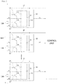
- FIG. 5 is a side view of a control device for controlling the operation of the vacuum interrupter tube according to an embodiment of the present invention.
- a control device 500 of a vacuum interrupter tube includes a permanent magnet 510 having opposite polarities at respective end terminals and guiding the short or short release of the vacuum interrupter tube 100.
- both sides thereof from the center have N and S polarities.
- the permanent magnet 510 is connected to the movable contact bolt 112, which is inserted into the vacuum interrupter tube 100. Accordingly, the movable contact bolt 112 is interlocked to the permanent magnet 510 and moves according to the movement of the permanent magnet 510, and then the short or release of the short is performed in the vacuum interrupter tube 100.
- the control device 500 of the vacuum interrupter tube includes a soft magnetic core 520.
- This core 520 may be fixedly installed.
- the permanent magnet 510 contacts the core 520 with its own magnetic force at ordinary times or during normal operation.
- the short release occurs when the movable contact bolt 112 of the vacuum interrupter tube 100, which is connected to the permanent magnet 510, moves toward the core 520 and is separated from the internal fixed contact bolt by allowing the permanent magnet 510 to contact the core 520.
- the permanent magnet 510 moves toward the core 520 to contact the core 520 for the short release in the vacuum interrupter tube 100.
- the coil 530 is wound multiple times around the core 520.
- This coil 530 serves to form an electromagnet by inducing magnetism to the core 520 through the application of power.
- the polarity of magnetism induced at both ends of the core 520 may be determined according to the winding direction and current direction of the coil 530.
- control device 500 of the vacuum interrupter tube includes a power source unit 540 for applying power to the coil 530.
- the power unit 540 applies power to the coil 530 under the control of the control unit 550, which will be described later.
- the electromagnet is realized by inducing magnetism to the core 520.
- control device 500 of the vacuum interrupter tube includes a control unit 550, which performs control so that the power unit 540 supplies power and cuts off power.
- the control unit 550 determines normal operation or the occurrence of failure, and according to the determination result, determines whether to supply power or stop the supply of power to the coil 530 for shorting and releasing a short in the vacuum interrupter tube 100.
- the control unit 550 maintains the cut-off state of the supply of power to the coil 530 during normal operation of the converter.
- the permanent magnet 510 since no magnetism is generated in the core 520, the permanent magnet 510 remains in contact with the core 520 due to the magnetic force thereof. According to such contact, the movable contact bolt 112 connected to the permanent magnet 510 also moves toward the core 520, and is separated from the fixed contact bolt 111.
- the movable contactor 102 added to the end portion of the movable contact bolt 112 moves to be separated from the fixed contactor 101 added to the end portion of the fixed contact bolt 111, so that a short circuit is not formed.
- the control unit 550 detects this and controls the power source unit 540 to supply power to the coil 530. In this way, when the power is supplied to the coil 530, magnetism is induced to a soft magnetic core 520. At this point, the current direction or the winding direction is determined, so that the polarity of the magnetism induced to both end portions of the core 520 and the polarity of the permanent magnet 510 corresponding thereto are identical. In this way, as both sides show the same polarity, the already fixed core 520 pushes out the permanent magnet 510, and then the permanent magnet 510 moves toward the vacuum interrupter tube 100.
- the movable contact bolt 112 connected to the permanent magnet 510 also moves, and allows the movable contactor 102 to contact the fixed contactor 101, and the vacuum interrupter tube 100 forms a short circuit.
- the first and second output terminals X1 and X2 of the sub-module 10 connected to the fixed contact bolt 111 and the movable contact bolt 112 contact each other to be shorted.
- everything from failure detection by the control unit 550 to short formation in the vacuum interrupter tube 100 takes place within several msec.
- both end portions of the core 520 and the permanent magnet 510 corresponding thereto have identical polarity.
- the coil 530 is wound around the core 520 in a direction such that both side polarities are identical.
- the movable contactor 102 continuously contacts the fixed contactor 101 by the pressure difference between the inside and outside and the holding power of the vacuum interrupter tube 100.
- the pressure difference and holding power are better to be larger than the magnetic force of the permanent magnet 510, which tends to contact the core 520 again.
- the interval between the permanent magnet 510 and the core 520 may be maintained sufficiently large and constant.
Landscapes
- Engineering & Computer Science (AREA)
- Power Engineering (AREA)
- Physics & Mathematics (AREA)
- Electromagnetism (AREA)
- Inverter Devices (AREA)
Claims (4)
- Eine Überbrückungsvorrichtung für einen Konverter, wobei der Konverter eine Energiespeichereinheit und eine Mehrzahl von Submodulen (10) aufweist, welche zumindest einen Leistungshalbleiterschaltkreis aufweisen, welcher parallel zur Energiespeichereinheit geschaltet ist und welcher eine Mehrzahl von Leistungshalbleiterschaltern und Freilaufdioden aufweist, wobei die Überbrückungsvorrichtung aufweist:eine Vakuum-Unterbrecher-Röhre (100), welche eingerichtet ist zum Kurzschließen eines ersten Verbindungsanschlusses (X1) und eines zweiten Verbindungsanschlusses (X2) eines Submoduls (10) mittels In-Kontakt-Bringens eines bewegbaren Kontaktstifts mit einem festen Kontaktstift, wenn ein Fehler in einem spezifischen Submodul der Mehrzahl von Submodulen auftritt, mit welchem die Überbrückungsvorrichtung verbindbar ist, und zum Überbrücken eines Phase-Stroms von dem spezifischen Submodul (10), in welchem der Fehler auftritt, wenn der Fehler in dem spezifischen Submodul (10) auftritt, undeine Steuerungsvorrichtung (500), welche eingerichtet ist zum Steuern eines Betriebs der Vakuum-Unterbrecher-Röhre (100),wobei die Steuerungsvorrichtung (500) aufweist einen Permanentmagneten (510), welcher eine N- und eine S-Polarität an jeweiligen Seiten von seinem Zentrum hat, welcher mit dem bewegbaren Kontaktstift der Vakuum-Unterbrecher-Röhre verbunden ist, und welcher den bewegbaren Kontaktstift zum festen Kontaktstift der Vakuum-Unterbrecher-Röhre bewegt, um den ersten Verbindungsanschluss und den zweiten Verbindungsanschluss der Vakuum-Unterbrecher-Röhre (100) kurzzuschließen, einen Kern (520), welcher eine ,C'-Typ-Form hat und fest installiert ist, um es der N- und der S-Polarität des Permanentmagneten (510) zu erlauben, in zugeordneter Weise beide Endabschnitte des ,C'-Typ-förmigen Kerns zu berühren oder von diesen getrennt zu sein, eine Spule (530), welche um den Kern (520) gewickelt ist, eine Leistungsquelle-Einheit (540), welche der Spule (530) Leistung zuführt, und eine Steuereinheit (550), welche die Leistung steuert, welche von der Leistungsquelle-Einheit (540) der Spule (530) zugeführt wird,wobei die Steuereinheit einen Ausschalt-Zustand der Leistung zur Spule während eines normalen Betriebs des spezifischen Submoduls beibehält, sodass kein Magnetismus im Kern erzeugt wird und die beiden Seiten des Permanentmagneten mit den beiden Endabschnitten des ,C'-Typ-förmigen Kerns in Kontakt bleiben aufgrund magnetischer Kräfte der N- und der S-Polarität der beiden Seiten des Permanentmagneten,wobei die Steuereinheit (550) die Leistungsquelle-Einheit (540) steuert, um zu erlauben, dass der Spule (530) Leistung zugeführt wird zu der Zeit des Auftretens des Fehlers in dem spezifischen Submodul (10), sodass die Polaritäten der beiden Endabschnitte des ,C'-Typ-förmigen Kerns identisch sind zu denen der jeweiligen Seiten des Permanentmagneten, sodass der feste Kern den Permanentmagneten (510) mit Magnetismus, welcher beim Kern (520) induziert wird, drückt, um die Vakuum-Unterbrecher-Röhre (100) kurzzuschließen, um den Phase-Strom zu überbrücken, und sodass, sogar falls die Leistung zur Spule nach dem Kurzschluss in der Vakuum-Unterbrecher-Röhre abgeschaltet ist, der Kurzschluss in der Vakuum-Unterbrecher-Röhre unverändert beibehalten wird.
- Die Überbrückungsvorrichtung gemäß Anspruch 1, wobei die Steuereinheit eine Steuerung durchführt, um die Leistung zur Spule (530) abzuschalten, um einen Zustand beizubehalten, in welchem der Permanentmagnet (510) den Kern (520) berührt.
- Die Überbrückungsvorrichtung gemäß Anspruch 1, wobei die Spule (530) mehrere Male um den Kern (520) in einer Richtung gewickelt ist, sodass Polaritäten der Endabschnitte des Kerns (520) und des Permanentmagneten (510) identisch sind.
- Die Überbrückungsvorrichtung gemäß Anspruch 1, wobei ein konstantes Intervall beibehalten wird, sodass der Permanentmagnet (510) den Kern (520) nicht berührt, nachdem die Leistung zur Spule (530) abgeschaltet ist.
Applications Claiming Priority (2)
| Application Number | Priority Date | Filing Date | Title |
|---|---|---|---|
| KR1020120154668A KR101449736B1 (ko) | 2012-12-27 | 2012-12-27 | 컨버터의 바이패스 장치 |
| PCT/KR2013/012337 WO2014104831A1 (ko) | 2012-12-27 | 2013-12-27 | 컨버터의 바이패스 장치 |
Publications (3)
| Publication Number | Publication Date |
|---|---|
| EP2940844A1 EP2940844A1 (de) | 2015-11-04 |
| EP2940844A4 EP2940844A4 (de) | 2016-11-23 |
| EP2940844B1 true EP2940844B1 (de) | 2021-08-18 |
Family
ID=51021768
Family Applications (1)
| Application Number | Title | Priority Date | Filing Date |
|---|---|---|---|
| EP13868169.7A Active EP2940844B1 (de) | 2012-12-27 | 2013-12-27 | Bypassvorrichtung für einen wechselrichter |
Country Status (4)
| Country | Link |
|---|---|
| US (1) | US9712042B2 (de) |
| EP (1) | EP2940844B1 (de) |
| KR (1) | KR101449736B1 (de) |
| WO (1) | WO2014104831A1 (de) |
Families Citing this family (9)
| Publication number | Priority date | Publication date | Assignee | Title |
|---|---|---|---|---|
| US9419539B2 (en) * | 2014-08-25 | 2016-08-16 | General Electric Company | Systems and methods for enhanced operation and protection of power converters |
| KR101617412B1 (ko) | 2015-11-20 | 2016-05-02 | 홍창호 | 퀵 커플러 감지장치 |
| US9812946B2 (en) * | 2016-02-03 | 2017-11-07 | Delta Electronics, Inc. | Power converter and operating method thereof |
| WO2018001515A1 (en) * | 2016-07-01 | 2018-01-04 | Abb Schweiz Ag | Detection of high current time derivatives in a cell of a modular multilevel converter |
| CN106783298A (zh) * | 2016-12-28 | 2017-05-31 | 滁州品之达电器科技有限公司 | 一种新型高压无弧开关装置 |
| KR20190002819U (ko) | 2018-05-03 | 2019-11-13 | 엘에스산전 주식회사 | 바이패스 스위치 |
| EP3696963B1 (de) * | 2019-02-12 | 2022-03-30 | General Electric Technology GmbH | Elektrische anordnung |
| KR102177141B1 (ko) | 2019-08-21 | 2020-11-10 | 효성중공업 주식회사 | 바이패스 스위치를 구비한 전력용 컨버터의 서브모듈 |
| CN112992564B (zh) * | 2019-12-17 | 2023-11-28 | 北京京人电器有限公司 | 一种换相开关 |
Family Cites Families (9)
| Publication number | Priority date | Publication date | Assignee | Title |
|---|---|---|---|---|
| JP3664899B2 (ja) * | 1998-11-27 | 2005-06-29 | 株式会社東芝 | 真空開閉装置 |
| SE521885C2 (sv) * | 2001-04-11 | 2003-12-16 | Abb Ab | Strömriktare |
| JP3723174B2 (ja) * | 2002-11-15 | 2005-12-07 | 三菱電機株式会社 | 操作装置、操作装置の製造方法及びこの操作装置を備えた開閉装置 |
| DE10309697B3 (de) * | 2003-02-26 | 2004-09-02 | Siemens Ag | Magnetischer Linearantrieb |
| US7508645B2 (en) * | 2004-07-09 | 2009-03-24 | Abb Technology Ag | Method and apparatus for operating a magnetic actuator in a power switching device |
| DE102007018344B4 (de) * | 2007-04-16 | 2022-08-04 | Siemens Energy Global GmbH & Co. KG | Vorrichtung zum Schutz von Umrichtermodulen |
| CN201051475Y (zh) * | 2007-07-03 | 2008-04-23 | 北京交通大学 | 一种永磁保持状态节能继电器 |
| JP5664966B2 (ja) | 2011-01-14 | 2015-02-04 | 株式会社安川電機 | 直列多重電力変換装置 |
| KR101389579B1 (ko) * | 2012-12-28 | 2014-04-29 | 주식회사 효성 | 전력용 컨버터 |
-
2012
- 2012-12-27 KR KR1020120154668A patent/KR101449736B1/ko active Active
-
2013
- 2013-12-27 EP EP13868169.7A patent/EP2940844B1/de active Active
- 2013-12-27 WO PCT/KR2013/012337 patent/WO2014104831A1/ko not_active Ceased
- 2013-12-27 US US14/758,022 patent/US9712042B2/en active Active
Non-Patent Citations (1)
| Title |
|---|
| None * |
Also Published As
| Publication number | Publication date |
|---|---|
| KR20140084795A (ko) | 2014-07-07 |
| WO2014104831A1 (ko) | 2014-07-03 |
| KR101449736B1 (ko) | 2014-10-08 |
| US9712042B2 (en) | 2017-07-18 |
| US20160197547A1 (en) | 2016-07-07 |
| EP2940844A4 (de) | 2016-11-23 |
| EP2940844A1 (de) | 2015-11-04 |
Similar Documents
| Publication | Publication Date | Title |
|---|---|---|
| US9712042B2 (en) | Bypass apparatus for converter | |
| US8093764B2 (en) | Method and system for bypassing a power cell of a power supply | |
| US10305368B2 (en) | Method and apparatus for bypassing Cascaded H-Bridge (CHB) power cells and power sub cell for multilevel inverter | |
| US7800254B2 (en) | System for bypassing a power cell of a power supply | |
| US8008923B2 (en) | Method for bypassing a power cell of a power supply | |
| US8390968B2 (en) | Apparatus for protection of converter modules | |
| KR101548840B1 (ko) | 고전압 dc 라인 상의 고장을 제거하기 위한 방법, 고전압 dc 라인을 통해 전류를 전송하기 위한 시스템, 및 컨버터 | |
| US8619396B2 (en) | Renewable one-time load break contactor | |
| CN103138589B (zh) | 用于运行转换器的方法和转换器 | |
| CN102754346A (zh) | 用于隔离开关的开关去负荷 | |
| JPWO2016207976A1 (ja) | 電力変換装置 | |
| US20210074490A1 (en) | Direct current circuit breaker device | |
| KR101496434B1 (ko) | 컨버터의 바이패스 스위치 장치 | |
| US8427092B2 (en) | High voltage DC electric power generating system with permanent magnet generator protection | |
| JP2017011992A (ja) | 送電系統システム、電力変換装置および開閉器 | |
| CN105788963A (zh) | 用于hvdc输电的旁路开关 | |
| CN107993878A (zh) | 一种高压断路器快速保护控制模块 | |
| US9893520B2 (en) | Switching device | |
| KR20170090928A (ko) | 바이패스 스위치 및 그를 갖는 모듈형 멀티레벨 컨버터 | |
| KR101599234B1 (ko) | 모듈러 멀티레벨 컨버터 바이패스 스위칭 장치 및 방법 | |
| US12609612B2 (en) | Power supply circuit and electric device | |
| JP2016134996A (ja) | 電力変換装置 | |
| EP3255779B1 (de) | Rekonfigurierbares, auf multi-permanentmagnetgenerator basierendes energieerzeugungssystem | |
| EP2595310A1 (de) | Elektrisches Hochspannungs-Gleichstromerzeugungssystem mit Permanentmagnetgeneratorschutz |
Legal Events
| Date | Code | Title | Description |
|---|---|---|---|
| PUAI | Public reference made under article 153(3) epc to a published international application that has entered the european phase |
Free format text: ORIGINAL CODE: 0009012 |
|
| 17P | Request for examination filed |
Effective date: 20150722 |
|
| AK | Designated contracting states |
Kind code of ref document: A1 Designated state(s): AL AT BE BG CH CY CZ DE DK EE ES FI FR GB GR HR HU IE IS IT LI LT LU LV MC MK MT NL NO PL PT RO RS SE SI SK SM TR |
|
| AX | Request for extension of the european patent |
Extension state: BA ME |
|
| DAX | Request for extension of the european patent (deleted) | ||
| A4 | Supplementary search report drawn up and despatched |
Effective date: 20161026 |
|
| RIC1 | Information provided on ipc code assigned before grant |
Ipc: H02M 1/32 20070101AFI20161020BHEP |
|
| STAA | Information on the status of an ep patent application or granted ep patent |
Free format text: STATUS: EXAMINATION IS IN PROGRESS |
|
| 17Q | First examination report despatched |
Effective date: 20180124 |
|
| RAP1 | Party data changed (applicant data changed or rights of an application transferred) |
Owner name: HYOSUNG HEAVY INDUSTRIES CORPORATION |
|
| GRAP | Despatch of communication of intention to grant a patent |
Free format text: ORIGINAL CODE: EPIDOSNIGR1 |
|
| STAA | Information on the status of an ep patent application or granted ep patent |
Free format text: STATUS: GRANT OF PATENT IS INTENDED |
|
| INTG | Intention to grant announced |
Effective date: 20210310 |
|
| GRAS | Grant fee paid |
Free format text: ORIGINAL CODE: EPIDOSNIGR3 |
|
| GRAA | (expected) grant |
Free format text: ORIGINAL CODE: 0009210 |
|
| STAA | Information on the status of an ep patent application or granted ep patent |
Free format text: STATUS: THE PATENT HAS BEEN GRANTED |
|
| AK | Designated contracting states |
Kind code of ref document: B1 Designated state(s): AL AT BE BG CH CY CZ DE DK EE ES FI FR GB GR HR HU IE IS IT LI LT LU LV MC MK MT NL NO PL PT RO RS SE SI SK SM TR |
|
| REG | Reference to a national code |
Ref country code: GB Ref legal event code: FG4D |
|
| REG | Reference to a national code |
Ref country code: CH Ref legal event code: EP |
|
| REG | Reference to a national code |
Ref country code: DE Ref legal event code: R096 Ref document number: 602013078890 Country of ref document: DE |
|
| REG | Reference to a national code |
Ref country code: IE Ref legal event code: FG4D Ref country code: AT Ref legal event code: REF Ref document number: 1422523 Country of ref document: AT Kind code of ref document: T Effective date: 20210915 |
|
| REG | Reference to a national code |
Ref country code: LT Ref legal event code: MG9D |
|
| REG | Reference to a national code |
Ref country code: NL Ref legal event code: MP Effective date: 20210818 |
|
| REG | Reference to a national code |
Ref country code: AT Ref legal event code: MK05 Ref document number: 1422523 Country of ref document: AT Kind code of ref document: T Effective date: 20210818 |
|
| PG25 | Lapsed in a contracting state [announced via postgrant information from national office to epo] |
Ref country code: RS Free format text: LAPSE BECAUSE OF FAILURE TO SUBMIT A TRANSLATION OF THE DESCRIPTION OR TO PAY THE FEE WITHIN THE PRESCRIBED TIME-LIMIT Effective date: 20210818 Ref country code: SE Free format text: LAPSE BECAUSE OF FAILURE TO SUBMIT A TRANSLATION OF THE DESCRIPTION OR TO PAY THE FEE WITHIN THE PRESCRIBED TIME-LIMIT Effective date: 20210818 Ref country code: HR Free format text: LAPSE BECAUSE OF FAILURE TO SUBMIT A TRANSLATION OF THE DESCRIPTION OR TO PAY THE FEE WITHIN THE PRESCRIBED TIME-LIMIT Effective date: 20210818 Ref country code: AT Free format text: LAPSE BECAUSE OF FAILURE TO SUBMIT A TRANSLATION OF THE DESCRIPTION OR TO PAY THE FEE WITHIN THE PRESCRIBED TIME-LIMIT Effective date: 20210818 Ref country code: BG Free format text: LAPSE BECAUSE OF FAILURE TO SUBMIT A TRANSLATION OF THE DESCRIPTION OR TO PAY THE FEE WITHIN THE PRESCRIBED TIME-LIMIT Effective date: 20211118 Ref country code: LT Free format text: LAPSE BECAUSE OF FAILURE TO SUBMIT A TRANSLATION OF THE DESCRIPTION OR TO PAY THE FEE WITHIN THE PRESCRIBED TIME-LIMIT Effective date: 20210818 Ref country code: PT Free format text: LAPSE BECAUSE OF FAILURE TO SUBMIT A TRANSLATION OF THE DESCRIPTION OR TO PAY THE FEE WITHIN THE PRESCRIBED TIME-LIMIT Effective date: 20211220 Ref country code: NO Free format text: LAPSE BECAUSE OF FAILURE TO SUBMIT A TRANSLATION OF THE DESCRIPTION OR TO PAY THE FEE WITHIN THE PRESCRIBED TIME-LIMIT Effective date: 20211118 Ref country code: FI Free format text: LAPSE BECAUSE OF FAILURE TO SUBMIT A TRANSLATION OF THE DESCRIPTION OR TO PAY THE FEE WITHIN THE PRESCRIBED TIME-LIMIT Effective date: 20210818 Ref country code: ES Free format text: LAPSE BECAUSE OF FAILURE TO SUBMIT A TRANSLATION OF THE DESCRIPTION OR TO PAY THE FEE WITHIN THE PRESCRIBED TIME-LIMIT Effective date: 20210818 |
|
| PG25 | Lapsed in a contracting state [announced via postgrant information from national office to epo] |
Ref country code: PL Free format text: LAPSE BECAUSE OF FAILURE TO SUBMIT A TRANSLATION OF THE DESCRIPTION OR TO PAY THE FEE WITHIN THE PRESCRIBED TIME-LIMIT Effective date: 20210818 Ref country code: LV Free format text: LAPSE BECAUSE OF FAILURE TO SUBMIT A TRANSLATION OF THE DESCRIPTION OR TO PAY THE FEE WITHIN THE PRESCRIBED TIME-LIMIT Effective date: 20210818 Ref country code: GR Free format text: LAPSE BECAUSE OF FAILURE TO SUBMIT A TRANSLATION OF THE DESCRIPTION OR TO PAY THE FEE WITHIN THE PRESCRIBED TIME-LIMIT Effective date: 20211119 |
|
| PG25 | Lapsed in a contracting state [announced via postgrant information from national office to epo] |
Ref country code: NL Free format text: LAPSE BECAUSE OF FAILURE TO SUBMIT A TRANSLATION OF THE DESCRIPTION OR TO PAY THE FEE WITHIN THE PRESCRIBED TIME-LIMIT Effective date: 20210818 |
|
| PG25 | Lapsed in a contracting state [announced via postgrant information from national office to epo] |
Ref country code: DK Free format text: LAPSE BECAUSE OF FAILURE TO SUBMIT A TRANSLATION OF THE DESCRIPTION OR TO PAY THE FEE WITHIN THE PRESCRIBED TIME-LIMIT Effective date: 20210818 |
|
| REG | Reference to a national code |
Ref country code: DE Ref legal event code: R097 Ref document number: 602013078890 Country of ref document: DE |
|
| PG25 | Lapsed in a contracting state [announced via postgrant information from national office to epo] |
Ref country code: SM Free format text: LAPSE BECAUSE OF FAILURE TO SUBMIT A TRANSLATION OF THE DESCRIPTION OR TO PAY THE FEE WITHIN THE PRESCRIBED TIME-LIMIT Effective date: 20210818 Ref country code: SK Free format text: LAPSE BECAUSE OF FAILURE TO SUBMIT A TRANSLATION OF THE DESCRIPTION OR TO PAY THE FEE WITHIN THE PRESCRIBED TIME-LIMIT Effective date: 20210818 Ref country code: RO Free format text: LAPSE BECAUSE OF FAILURE TO SUBMIT A TRANSLATION OF THE DESCRIPTION OR TO PAY THE FEE WITHIN THE PRESCRIBED TIME-LIMIT Effective date: 20210818 Ref country code: EE Free format text: LAPSE BECAUSE OF FAILURE TO SUBMIT A TRANSLATION OF THE DESCRIPTION OR TO PAY THE FEE WITHIN THE PRESCRIBED TIME-LIMIT Effective date: 20210818 Ref country code: CZ Free format text: LAPSE BECAUSE OF FAILURE TO SUBMIT A TRANSLATION OF THE DESCRIPTION OR TO PAY THE FEE WITHIN THE PRESCRIBED TIME-LIMIT Effective date: 20210818 Ref country code: AL Free format text: LAPSE BECAUSE OF FAILURE TO SUBMIT A TRANSLATION OF THE DESCRIPTION OR TO PAY THE FEE WITHIN THE PRESCRIBED TIME-LIMIT Effective date: 20210818 |
|
| PLBE | No opposition filed within time limit |
Free format text: ORIGINAL CODE: 0009261 |
|
| STAA | Information on the status of an ep patent application or granted ep patent |
Free format text: STATUS: NO OPPOSITION FILED WITHIN TIME LIMIT |
|
| REG | Reference to a national code |
Ref country code: DE Ref legal event code: R119 Ref document number: 602013078890 Country of ref document: DE |
|
| 26N | No opposition filed |
Effective date: 20220519 |
|
| PG25 | Lapsed in a contracting state [announced via postgrant information from national office to epo] |
Ref country code: MC Free format text: LAPSE BECAUSE OF FAILURE TO SUBMIT A TRANSLATION OF THE DESCRIPTION OR TO PAY THE FEE WITHIN THE PRESCRIBED TIME-LIMIT Effective date: 20210818 Ref country code: IT Free format text: LAPSE BECAUSE OF FAILURE TO SUBMIT A TRANSLATION OF THE DESCRIPTION OR TO PAY THE FEE WITHIN THE PRESCRIBED TIME-LIMIT Effective date: 20210818 |
|
| REG | Reference to a national code |
Ref country code: CH Ref legal event code: PL |
|
| PG25 | Lapsed in a contracting state [announced via postgrant information from national office to epo] |
Ref country code: SI Free format text: LAPSE BECAUSE OF FAILURE TO SUBMIT A TRANSLATION OF THE DESCRIPTION OR TO PAY THE FEE WITHIN THE PRESCRIBED TIME-LIMIT Effective date: 20210818 |
|
| REG | Reference to a national code |
Ref country code: BE Ref legal event code: MM Effective date: 20211231 |
|
| PG25 | Lapsed in a contracting state [announced via postgrant information from national office to epo] |
Ref country code: LU Free format text: LAPSE BECAUSE OF NON-PAYMENT OF DUE FEES Effective date: 20211227 Ref country code: IE Free format text: LAPSE BECAUSE OF NON-PAYMENT OF DUE FEES Effective date: 20211227 Ref country code: DE Free format text: LAPSE BECAUSE OF NON-PAYMENT OF DUE FEES Effective date: 20220701 |
|
| PG25 | Lapsed in a contracting state [announced via postgrant information from national office to epo] |
Ref country code: FR Free format text: LAPSE BECAUSE OF NON-PAYMENT OF DUE FEES Effective date: 20211231 Ref country code: BE Free format text: LAPSE BECAUSE OF NON-PAYMENT OF DUE FEES Effective date: 20211231 |
|
| PG25 | Lapsed in a contracting state [announced via postgrant information from national office to epo] |
Ref country code: LI Free format text: LAPSE BECAUSE OF NON-PAYMENT OF DUE FEES Effective date: 20211231 Ref country code: CH Free format text: LAPSE BECAUSE OF NON-PAYMENT OF DUE FEES Effective date: 20211231 |
|
| PG25 | Lapsed in a contracting state [announced via postgrant information from national office to epo] |
Ref country code: HU Free format text: LAPSE BECAUSE OF FAILURE TO SUBMIT A TRANSLATION OF THE DESCRIPTION OR TO PAY THE FEE WITHIN THE PRESCRIBED TIME-LIMIT; INVALID AB INITIO Effective date: 20131227 |
|
| PG25 | Lapsed in a contracting state [announced via postgrant information from national office to epo] |
Ref country code: CY Free format text: LAPSE BECAUSE OF FAILURE TO SUBMIT A TRANSLATION OF THE DESCRIPTION OR TO PAY THE FEE WITHIN THE PRESCRIBED TIME-LIMIT Effective date: 20210818 |
|
| PG25 | Lapsed in a contracting state [announced via postgrant information from national office to epo] |
Ref country code: MK Free format text: LAPSE BECAUSE OF FAILURE TO SUBMIT A TRANSLATION OF THE DESCRIPTION OR TO PAY THE FEE WITHIN THE PRESCRIBED TIME-LIMIT Effective date: 20210818 |
|
| PG25 | Lapsed in a contracting state [announced via postgrant information from national office to epo] |
Ref country code: MT Free format text: LAPSE BECAUSE OF FAILURE TO SUBMIT A TRANSLATION OF THE DESCRIPTION OR TO PAY THE FEE WITHIN THE PRESCRIBED TIME-LIMIT Effective date: 20210818 |
|
| PG25 | Lapsed in a contracting state [announced via postgrant information from national office to epo] |
Ref country code: TR Free format text: LAPSE BECAUSE OF FAILURE TO SUBMIT A TRANSLATION OF THE DESCRIPTION OR TO PAY THE FEE WITHIN THE PRESCRIBED TIME-LIMIT Effective date: 20210818 |
|
| PGFP | Annual fee paid to national office [announced via postgrant information from national office to epo] |
Ref country code: GB Payment date: 20251001 Year of fee payment: 13 |