EP2940766B1 - Fuel cell stack - Google Patents
Fuel cell stack Download PDFInfo
- Publication number
- EP2940766B1 EP2940766B1 EP13869338.7A EP13869338A EP2940766B1 EP 2940766 B1 EP2940766 B1 EP 2940766B1 EP 13869338 A EP13869338 A EP 13869338A EP 2940766 B1 EP2940766 B1 EP 2940766B1
- Authority
- EP
- European Patent Office
- Prior art keywords
- cooling fluid
- absorbing member
- functional parts
- displacement absorbing
- fuel cell
- Prior art date
- Legal status (The legal status is an assumption and is not a legal conclusion. Google has not performed a legal analysis and makes no representation as to the accuracy of the status listed.)
- Active
Links
- 239000000446 fuel Substances 0.000 title claims description 73
- 238000006073 displacement reaction Methods 0.000 claims description 142
- 239000012809 cooling fluid Substances 0.000 claims description 124
- 239000012528 membrane Substances 0.000 claims description 21
- 230000007423 decrease Effects 0.000 claims description 10
- 230000037361 pathway Effects 0.000 claims description 8
- 230000003247 decreasing effect Effects 0.000 claims description 7
- 239000007789 gas Substances 0.000 description 24
- 230000009467 reduction Effects 0.000 description 10
- 230000005611 electricity Effects 0.000 description 9
- 239000010410 layer Substances 0.000 description 9
- 239000002826 coolant Substances 0.000 description 7
- QVGXLLKOCUKJST-UHFFFAOYSA-N atomic oxygen Chemical compound [O] QVGXLLKOCUKJST-UHFFFAOYSA-N 0.000 description 5
- 230000008859 change Effects 0.000 description 5
- 239000001301 oxygen Substances 0.000 description 5
- 229910052760 oxygen Inorganic materials 0.000 description 5
- UFHFLCQGNIYNRP-UHFFFAOYSA-N Hydrogen Chemical compound [H][H] UFHFLCQGNIYNRP-UHFFFAOYSA-N 0.000 description 4
- 239000001257 hydrogen Substances 0.000 description 4
- 229910052739 hydrogen Inorganic materials 0.000 description 4
- 230000002829 reductive effect Effects 0.000 description 4
- 239000003792 electrolyte Substances 0.000 description 3
- 239000011159 matrix material Substances 0.000 description 3
- 239000002184 metal Substances 0.000 description 3
- 238000000465 moulding Methods 0.000 description 3
- 230000000694 effects Effects 0.000 description 2
- 239000000463 material Substances 0.000 description 2
- 239000005518 polymer electrolyte Substances 0.000 description 2
- 230000003014 reinforcing effect Effects 0.000 description 2
- 239000007787 solid Substances 0.000 description 2
- 230000008961 swelling Effects 0.000 description 2
- 230000000712 assembly Effects 0.000 description 1
- 238000000429 assembly Methods 0.000 description 1
- 230000015556 catabolic process Effects 0.000 description 1
- 239000003054 catalyst Substances 0.000 description 1
- 239000012141 concentrate Substances 0.000 description 1
- 230000008094 contradictory effect Effects 0.000 description 1
- 238000001816 cooling Methods 0.000 description 1
- 238000006731 degradation reaction Methods 0.000 description 1
- 230000006866 deterioration Effects 0.000 description 1
- 238000009792 diffusion process Methods 0.000 description 1
- 238000003487 electrochemical reaction Methods 0.000 description 1
- 125000000524 functional group Chemical group 0.000 description 1
- 238000001746 injection moulding Methods 0.000 description 1
- 239000011229 interlayer Substances 0.000 description 1
- 230000036961 partial effect Effects 0.000 description 1
- 239000011295 pitch Substances 0.000 description 1
- 229920000642 polymer Polymers 0.000 description 1
- 238000004080 punching Methods 0.000 description 1
- 239000012495 reaction gas Substances 0.000 description 1
- 239000011347 resin Substances 0.000 description 1
- 229920005989 resin Polymers 0.000 description 1
- 230000004044 response Effects 0.000 description 1
- 230000002441 reversible effect Effects 0.000 description 1
- 238000007789 sealing Methods 0.000 description 1
- 239000000243 solution Substances 0.000 description 1
- 125000006850 spacer group Chemical group 0.000 description 1
- 229910001220 stainless steel Inorganic materials 0.000 description 1
- 239000010935 stainless steel Substances 0.000 description 1
- 238000011144 upstream manufacturing Methods 0.000 description 1
Images


Classifications
-
- H—ELECTRICITY
- H01—ELECTRIC ELEMENTS
- H01M—PROCESSES OR MEANS, e.g. BATTERIES, FOR THE DIRECT CONVERSION OF CHEMICAL ENERGY INTO ELECTRICAL ENERGY
- H01M8/00—Fuel cells; Manufacture thereof
- H01M8/02—Details
- H01M8/0202—Collectors; Separators, e.g. bipolar separators; Interconnectors
- H01M8/0204—Non-porous and characterised by the material
- H01M8/0206—Metals or alloys
-
- H—ELECTRICITY
- H01—ELECTRIC ELEMENTS
- H01M—PROCESSES OR MEANS, e.g. BATTERIES, FOR THE DIRECT CONVERSION OF CHEMICAL ENERGY INTO ELECTRICAL ENERGY
- H01M8/00—Fuel cells; Manufacture thereof
- H01M8/02—Details
- H01M8/0202—Collectors; Separators, e.g. bipolar separators; Interconnectors
- H01M8/0258—Collectors; Separators, e.g. bipolar separators; Interconnectors characterised by the configuration of channels, e.g. by the flow field of the reactant or coolant
- H01M8/0265—Collectors; Separators, e.g. bipolar separators; Interconnectors characterised by the configuration of channels, e.g. by the flow field of the reactant or coolant the reactant or coolant channels having varying cross sections
-
- H—ELECTRICITY
- H01—ELECTRIC ELEMENTS
- H01M—PROCESSES OR MEANS, e.g. BATTERIES, FOR THE DIRECT CONVERSION OF CHEMICAL ENERGY INTO ELECTRICAL ENERGY
- H01M8/00—Fuel cells; Manufacture thereof
- H01M8/02—Details
- H01M8/0202—Collectors; Separators, e.g. bipolar separators; Interconnectors
- H01M8/0267—Collectors; Separators, e.g. bipolar separators; Interconnectors having heating or cooling means, e.g. heaters or coolant flow channels
-
- H—ELECTRICITY
- H01—ELECTRIC ELEMENTS
- H01M—PROCESSES OR MEANS, e.g. BATTERIES, FOR THE DIRECT CONVERSION OF CHEMICAL ENERGY INTO ELECTRICAL ENERGY
- H01M8/00—Fuel cells; Manufacture thereof
- H01M8/02—Details
- H01M8/0297—Arrangements for joining electrodes, reservoir layers, heat exchange units or bipolar separators to each other
-
- H—ELECTRICITY
- H01—ELECTRIC ELEMENTS
- H01M—PROCESSES OR MEANS, e.g. BATTERIES, FOR THE DIRECT CONVERSION OF CHEMICAL ENERGY INTO ELECTRICAL ENERGY
- H01M8/00—Fuel cells; Manufacture thereof
- H01M8/10—Fuel cells with solid electrolytes
- H01M8/1004—Fuel cells with solid electrolytes characterised by membrane-electrode assemblies [MEA]
-
- H—ELECTRICITY
- H01—ELECTRIC ELEMENTS
- H01M—PROCESSES OR MEANS, e.g. BATTERIES, FOR THE DIRECT CONVERSION OF CHEMICAL ENERGY INTO ELECTRICAL ENERGY
- H01M8/00—Fuel cells; Manufacture thereof
- H01M8/24—Grouping of fuel cells, e.g. stacking of fuel cells
- H01M8/241—Grouping of fuel cells, e.g. stacking of fuel cells with solid or matrix-supported electrolytes
-
- H—ELECTRICITY
- H01—ELECTRIC ELEMENTS
- H01M—PROCESSES OR MEANS, e.g. BATTERIES, FOR THE DIRECT CONVERSION OF CHEMICAL ENERGY INTO ELECTRICAL ENERGY
- H01M8/00—Fuel cells; Manufacture thereof
- H01M8/24—Grouping of fuel cells, e.g. stacking of fuel cells
- H01M8/2465—Details of groupings of fuel cells
- H01M8/2483—Details of groupings of fuel cells characterised by internal manifolds
-
- F—MECHANICAL ENGINEERING; LIGHTING; HEATING; WEAPONS; BLASTING
- F28—HEAT EXCHANGE IN GENERAL
- F28D—HEAT-EXCHANGE APPARATUS, NOT PROVIDED FOR IN ANOTHER SUBCLASS, IN WHICH THE HEAT-EXCHANGE MEDIA DO NOT COME INTO DIRECT CONTACT
- F28D21/00—Heat-exchange apparatus not covered by any of the groups F28D1/00 - F28D20/00
- F28D2021/0019—Other heat exchangers for particular applications; Heat exchange systems not otherwise provided for
- F28D2021/0043—Other heat exchangers for particular applications; Heat exchange systems not otherwise provided for for fuel cells
-
- F—MECHANICAL ENGINEERING; LIGHTING; HEATING; WEAPONS; BLASTING
- F28—HEAT EXCHANGE IN GENERAL
- F28D—HEAT-EXCHANGE APPARATUS, NOT PROVIDED FOR IN ANOTHER SUBCLASS, IN WHICH THE HEAT-EXCHANGE MEDIA DO NOT COME INTO DIRECT CONTACT
- F28D9/00—Heat-exchange apparatus having stationary plate-like or laminated conduit assemblies for both heat-exchange media, the media being in contact with different sides of a conduit wall
- F28D9/0031—Heat-exchange apparatus having stationary plate-like or laminated conduit assemblies for both heat-exchange media, the media being in contact with different sides of a conduit wall the conduits for one heat-exchange medium being formed by paired plates touching each other
- F28D9/0043—Heat-exchange apparatus having stationary plate-like or laminated conduit assemblies for both heat-exchange media, the media being in contact with different sides of a conduit wall the conduits for one heat-exchange medium being formed by paired plates touching each other the plates having openings therein for circulation of at least one heat-exchange medium from one conduit to another
- F28D9/005—Heat-exchange apparatus having stationary plate-like or laminated conduit assemblies for both heat-exchange media, the media being in contact with different sides of a conduit wall the conduits for one heat-exchange medium being formed by paired plates touching each other the plates having openings therein for circulation of at least one heat-exchange medium from one conduit to another the plates having openings therein for both heat-exchange media
-
- F—MECHANICAL ENGINEERING; LIGHTING; HEATING; WEAPONS; BLASTING
- F28—HEAT EXCHANGE IN GENERAL
- F28F—DETAILS OF HEAT-EXCHANGE AND HEAT-TRANSFER APPARATUS, OF GENERAL APPLICATION
- F28F2240/00—Spacing means
-
- F—MECHANICAL ENGINEERING; LIGHTING; HEATING; WEAPONS; BLASTING
- F28—HEAT EXCHANGE IN GENERAL
- F28F—DETAILS OF HEAT-EXCHANGE AND HEAT-TRANSFER APPARATUS, OF GENERAL APPLICATION
- F28F2265/00—Safety or protection arrangements; Arrangements for preventing malfunction
- F28F2265/26—Safety or protection arrangements; Arrangements for preventing malfunction for allowing differential expansion between elements
-
- H—ELECTRICITY
- H01—ELECTRIC ELEMENTS
- H01M—PROCESSES OR MEANS, e.g. BATTERIES, FOR THE DIRECT CONVERSION OF CHEMICAL ENERGY INTO ELECTRICAL ENERGY
- H01M8/00—Fuel cells; Manufacture thereof
- H01M8/10—Fuel cells with solid electrolytes
- H01M2008/1095—Fuel cells with polymeric electrolytes
-
- Y—GENERAL TAGGING OF NEW TECHNOLOGICAL DEVELOPMENTS; GENERAL TAGGING OF CROSS-SECTIONAL TECHNOLOGIES SPANNING OVER SEVERAL SECTIONS OF THE IPC; TECHNICAL SUBJECTS COVERED BY FORMER USPC CROSS-REFERENCE ART COLLECTIONS [XRACs] AND DIGESTS
- Y02—TECHNOLOGIES OR APPLICATIONS FOR MITIGATION OR ADAPTATION AGAINST CLIMATE CHANGE
- Y02E—REDUCTION OF GREENHOUSE GAS [GHG] EMISSIONS, RELATED TO ENERGY GENERATION, TRANSMISSION OR DISTRIBUTION
- Y02E60/00—Enabling technologies; Technologies with a potential or indirect contribution to GHG emissions mitigation
- Y02E60/30—Hydrogen technology
- Y02E60/50—Fuel cells
Definitions
- the present invention relates to a fuel cell such as a polymer electrolyte fuel cell (PEFC), particularly to a fuel cell stack that has a cooling fluid channel formed between stacked single cells.
- PEFC polymer electrolyte fuel cell
- Patent Document 1 One of such fuel cell stacks is described in, for example, Patent Document 1 where it is referred to as a fuel cell.
- the fuel cell described in Patent Document 1 is composed of a stacked plurality of fuel cells.
- Each of the fuel cells includes a hydrogen electrode with an uneven cross-section and an oxygen electrode including an drain layer with an uneven cross-section, which are disposed on opposite sides of an MEA (membrane electrode assembly), and further includes flat plate separators disposed on the outer sides of the hydrogen electrode and the oxygen electrodes to form a hydrogen channel and an oxygen channel in the respective interfaces with the electrodes.
- the fuel cell includes a coolant channel portion at the side of the oxygen electrode.
- the coolant channel portion includes two flat plate separators and a pre-compressed plate interposed between them, wherein a coolant channel is formed between the two flat plate separators.
- the pre-compressed plate has a corrugated cross-sectional shape so as to be elastically deformable in the thickness direction (stacking direction of the stack).
- the pre-compressed plate distributes a load that is locally generated due to a shape error of the components of the fuel cell so as to apply a uniform load to each component.
- the present invention was made in view of the above-described circumstances, and an object thereof is to provide a fuel cell stack that has a coolant channel formed between stacked single cells and includes a displacement absorbing member disposed in the coolant channel, wherein the pressure loss in the coolant channel can be reduced while retaining the spring characteristics of the displacement absorbing member.
- the fuel cell stack of the present invention is defined in appended claim 1. It includes, inter alia, a stacked plurality of single cells, each including a membrane electrode assembly and a pair of separators sandwiching the membrane electrode assembly, wherein a cooling fluid channel where a cooling fluid flows is formed between adjacent single cells, and the fuel cell stack further includes a displacement absorbing member disposed in the cooling fluid channel to absorb a displacement between the plurality of single cells. Furthermore, in the fuel cell stack, the displacement absorbing member includes a channel flow resistance reducing means that reduces the channel flow resistance of the cooling fluid channel against the cooling fluid.
- the pressure loss in the cooling fluid channel can be reduced while maintaining the spring characteristics of the displacement absorbing member.
- the fuel cell stack according to this embodiment which includes a stacked plurality of solid polymer electrolyte single cells, is used for, for example, a power source of vehicles such as electric cars.
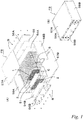
- the fuel cell stack FS of FIG. 1 (A) includes a plurality of rectangular plate single cells C that are stacked together to form a stack S, an end plate 56A provided on one end in the stacking direction (right end in FIG. 1 ) of the stack S via a current collector 54A and a spacer 55, and an end plate 56B provided on the other end via a current collector 54B.
- the fuel cell stack FS further includes fastening plates 57A, 57B provided on opposite surfaces of the stack S corresponding to the long sides of the single cells C (upper and lower surfaces in FIG. 1 ), and reinforcing plates 58A, 58B provided on opposite surfaces corresponding to the short sides.
- the fastening plate 57A, 57B and the reinforcing plates 58A, 58B are coupled to both of the end plates 56A, 56B by bolts B.
- the fuel cell stack FS has a case-integrated structure as illustrated in FIG. 1 (B) in which the stack S is restrained and pressed in the stacking direction so that a predetermined contact pressure is applied to each of the single cells C. With this structure, the gas sealing property and the electrical conductivity are maintained at a high level
- each of the single cells C includes a membrane electrode assembly 1 with a frame 51 along the periphery thereof, a pair of separators 2, 2 that forms cathode and anode gas channels (GC, GA) in the interfaces with the frame 51 and the membrane electrode assembly 1.
- the single cells C are configured such that gas flows in the opposite directions between the gas channels (GC, GA).
- the cathode gas is oxygen-containing gas (air), and the anode gas is hydrogen-containing gas.
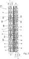
- the membrane electrode assembly 1 which is generally referred to as an MEA (membrane electrode assembly), includes an electrolyte layer 11 of a solid polymer, and a cathode layer 12 and an anode layer 13 sandwiching the electrolyte layer 11 as illustrated in FIG. 3 .
- each of the electrode layers 12, 13 includes an electrode catalyst layer in contact with the electrolyte layer 11 and a gas diffusion layer disposed on the outer side thereof.
- the frame 51 is integrally formed with the membrane electrode assembly 1 by resin molding (e.g. injection molding) such that the membrane electrode assembly 1 is positioned in the center.
- the frame 51 has manifold holes H1 to H3 and H4 to H6 that are arranged such that each short side has three manifold holes. Areas between the manifold holes and the membrane electrode assembly 1 serve as diffuser parts D.
- the frame 51 and the separators 2, 2 have a rectangular shape with substantially the same dimension.
- the frame 51 has a plurality of round protrusions 52 arranged in a matrix on both surfaces within the diffuser parts D as illustrated in FIG. 2 .
- the protrusions 52 come in contact with the separators 2, 2 to secure the space where reaction gas flows.
- the separators 2 are metal plates in which one plate has reversed faces to those of the other plate.
- the separators 2 are made of stainless steel and may be formed in any suitable shape by press working.
- the illustrated separators 2 are formed in an uneven cross-sectional shape at least in the center part corresponding to the membrane electrode assembly 1.
- each of the separators 2 continues in the length direction as illustrated in FIG. 2 .
- the apexes of the corrugation are in contact with the membrane electrode assembly 1 while the bottoms of the corrugation form the cathode and anode gas channels (GC, GA) between the bottoms and the membrane electrode assembly 1 as illustrated in the cross sectional view of FIG. 3 .
- each of the separators 2 has manifold holes H1 to H6 at both ends, which are similar to the manifold holes H1 to H6 of the frame 51.
- the manifold holes H1 to H3 on the left in FIG. 2 are configured respectively to supply anode gas (H1), to discharge cooling fluid (H2) and to discharge cathode gas (H3) from the top. These manifold holes are communicated with corresponding manifold holes in the stacking direction to form respective channels.
- the manifold holes H4 to H6 on the right in FIG. 2 are configured respectively to supply the cathode gas (H4), to supply the cooling fluid (H5) and to discharge the anode gas (H6) from the top. These manifold holes are communicated with corresponding manifold holes in the stacking direction to form respective channels.
- each of the single cells C includes a gas sealers SL provided between the frame 51 and the separators 2 at the edge part thereof and around the manifold holes H1 to H6.
- the gas sealer SL is also provided between the single cells C, i.e. between adjacent separators 2.
- the gas sealers SL airtightly separate the respective interlayers.
- the gas sealers SL have openings or are selectively removed in the periphery of the manifold holes H1 to H6 so as to allow the cathode gas, the anode gas and the cooling fluid to flow only within the respective flow areas.
- the plurality of single cells C are stacked together to form the fuel cell stack FS. As illustrated in FIG. 3 , a cooling fluid channel F is formed between adjacent single cells C, and a displacement absorbing member 5 to absorb a displacement between the single cells C is interposed in the cooling fluid channel F.
- the displacement absorbing member 5 includes a channel flow resistance reducing means that reduces the channel flow resistance of the cooling fluid channel F against the cooling fluid.
- the channel flow resistance reducing means reduces the channel flow resistance by reducing the projected area of the displacement absorbing means projected in the flowing direction of the cooling fluid at an arbitrary location in the flowing direction or by preventing vortex flow of the cooling fluid, or the like.
- the displacement absorbing member 5 is configured such that a contacting part in contact with the separator 2 moves in the in-plane direction according to a deformation in the thickness direction.
- the surfaces of the separators 2 facing the cooling fluid channel F have an uneven cross-sectional shape that continues in the flow direction of the cooling fluid. That is, the continuing direction corresponds to the flow direction of the cooling fluid.
- the flow direction of the cooling fluid corresponds to the horizontal direction in FIG. 2 or the direction perpendicular to the paper plane in FIG. 3 .
- the displacement absorbing member 5 is disposed so that the moving direction of the contacting part corresponds to the flow direction of the cooling fluid.
- the displacement absorbing member 5 of this embodiment is made of a thin metal plate. As illustrated in the partial view of FIG. 4 (A) , a number of spring functional parts 5B are arranged in a matrix on one surface of a base plate 5A.
- the displacement absorbing member 5 is electrically conductive and thereby also has a function as a connector to electrically connect the single cells C to each other as well as the displacement absorbing function.
- Each of the spring functional parts 5B has a tongue-shaped cantilever structure with a fixed end K on the base plate 5A and a free tip end J. While the spring functional parts 5B of this embodiment have a rectangular shape, the shape is not particularly limited.
- the displacement absorbing member 5 is configured such that the contacting parts in contact with the separator 2 move in the in-plane direction according to a deformation in the thickness direction. That is, as illustrated in FIG. 4 (B) , the displacement absorbing member 5 is provided such that the base plate 5A is in contact with the separator 2 of a single cell at one side (lower side in FIG. 4 ) while the free ends J of the spring functional parts 5B are in contact with the separator 2 of a single cell at the other side.
- the spring functional parts 5B swings from the position illustrated by the solid line to the position illustrated by the virtual line (or the reverse direction). As the inclination angle of the spring functional parts 5B changes, the contacting parts of the free ends J in contact with the other separator 2 move in the in-plane direction by the distance L
- the displacement absorbing member 5 is disposed so that the moving direction of the contacting parts corresponds to the flow direction of the cooling fluid, i.e. the direction indicated by the arrow B in FIG. 4 .
- the free ends J of the spring functional parts 5B head downstream in the flow direction of the cooling fluid.
- the spring functional parts 5B have a flat cross-sectional shape in FIG. 4 , but they may have a suitable cross-sectional shape.
- the free ends J are curved so that the contacting parts in contact with the separator 2 are constituted of curved surfaces, they can slide more smoothly with respect to the separator 2.
- the spring functional parts 5B are formed by lancing the base plate A. Accordingly, the base plate 5A has openings 5C corresponding to the spring functional parts 5B.
- the displacement absorbing member 5 with such configuration can be easily produced from a single sheet by means of press working or the like.
- pathways 6 between the spring functional parts 5B arranged in the direction transverse to the flow direction of the cooling fluid correspond to the channel flow resistance reducing means. That is, the pathways 6 correspond to a means that reduces the channel flow resistance by reducing the projected area of the displacement absorbing means 5 projected in the flow direction of the cooling fluid in an arbitrary location in the flow direction. In this embodiment, since the spring functional parts 5B are arranged in a matrix, the pathways 6 continue in the flow direction of the cooling fluid.
- the fuel cell stack FS supplies the anode gas and the cathode gas to the membrane electrode assembly 1 through the gas channels GC, GA while allowing the cooling fluid to flow through the cooling fluid channel F between adjacent single cells C, so as to generate electric energy by an electrochemical reaction.
- the displacement absorbing member 5 absorbs the resultant displacement in the stacking direction.
- the displacement absorbing member 5 is interposed in the cooling fluid channel.
- the displacement absorbing member 5 has the pathways 6 as the channel flow resistance reducing means for the cooling fluid channel F, the cooling fluid flows smoothly.
- the fuel cell stack FS can reduce the pressure loss in the cooling fluid channel F while maintaining the spring characteristics of the displacement absorbing member 5 at a good level, which eventually enables reducing the size and weight of a pump for the cooling fluid.
- the fuel cell stack FS employs the means (pathways 6) that reduces the channel flow resistance by reducing the projected area of the displacement absorbing member 5 projected in the flow direction of the cooling fluid at an arbitrary location in the flow direction. Therefore, with such a simple configuration, smooth flow of the cooling fluid can be achieved, and the pressure loss in the cooling fluid channel F is reduced.
- the surfaces of the separators 2 facing the cooling fluid channel F have an uneven cross-sectional shape that continues in the flow direction of the cooling fluid
- the displacement absorbing member 5 includes the contacting portions in contact with the separator 2 configured to move in the in-plane direction according to a deformation in the thickness direction
- the displacement absorbing member 5 is disposed so that the moving direction of the contacting portions corresponds to the flow direction of the cooling fluid. Therefore, in the fuel cell stack FS, the displacement absorbing member 5 is prevented from being partly stuck in the recesses of the separators 2 when it moves in the in-plane direction, and the contact between them is maintained in a good condition.
- both surfaces of the separators 2 can be effectively utilized respectively as the gas channel CG (CA) and the cooling fluid channel F. This can reduce the thickness of the single cells C and thus reduce the size of the fuel cell stack FS.
- the displacement absorbing member 5 includes a number of spring functional parts 5B that are arranged on one surface of the base plate 5A, and the spring functional parts 5B have a cantilever structure with the fixed proximal end K fixed on the base plate 5A and the free tip end J. Therefore, the fuel cell stack FS can adequately absorb a displacement in the thickness direction with such a simple structure and can be therefore produced at a low cost.
- the spring functional parts 5B have a simple shape and can be easily formed at short pitches to decrease the spring stiffness. With such decreased spring stiffness, the displacement absorbing member 5 exhibits spring characteristics that causes small load change in response to a displacement. Even when the displacement absorbing member 5 is deteriorated due to displacements in the compressing direction during operation or time degradation, the deterioration causes small change in surface pressure, and the electrical contact resistance between components is stable.
- the spring functional parts 5B of the displacement absorbing member 5 are formed by lancing the base plate 5A. Therefore, as described above, the displacement absorbing member 5 can be easily formed from a single sheet by press working.
- the lacing for the spring functional parts 5B forms the openings 5C in the displacement absorbing member 5, and the cooling fluid can flow in the vertical direction through the openings 5C. Therefore, this can improve the cooling effect in addition to the reduction of the pressure loss.
- the displacement absorbing member 5 is disposed so that the free ends J of the spring functional parts 5B head downstream in the flow direction of the cooling fluid.
- the spring functional parts 5B inclined toward the flow direction of the cooling fluid prevent vortex flow in the downstream side of the spring functional parts 5B. This can further reduce the pressure loss in the cooling fluid channel F.
- the pressure loss in the cooling fluid channel F due to the displacement absorbing member 5 is contradictory to the spring function of the displacement absorbing member 5 and the electricity conducting function of the displacement absorbing member 5, as a connector between the single cells C. That is, in order to reduce the pressure loss in the cooling fluid channel F, the displacement absorbing member 5 can be formed in a shape and size that can minimize the resistance. However, such a shape and size degrade the spring function and the electricity conducting function of the displacement absorbing member 5.
- the displacement absorbing member 5 includes the pathways 6 as the channel flow resistance reducing means so that it has a reduced projected area projected in the flow direction of the cooling fluid in an arbitrary location in the flow direction. Furthermore, in the displacement absorbing member 5, the moving direction of the contacting portions in contact with the separator 2, which move according to a deformation in the thickness direction, corresponds to the flow direction of the cooling fluid, the spring functional parts 5B has a cantilever structure, the spring functional parts 5B are formed by lancing the base plate 5A so that the openings 5C are formed therein, and the spring functional parts 5B are disposed so that the free ends J head downstream in the flow direction of the cooling fluid.
- the fuel cell stack FS in which the displacement absorbing member 5 is disposed in the cooling fluid channel F between the stacked single cells C, achieves both of the reduction in pressure loss in the cooling fluid channel F by means of the displacement absorbing member 5 and the adequate spring function and the adequate electricity conducting function as a connector of the displacement absorbing member 5.
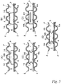
- FIG. 5 illustrates displacement absorbing members according to other embodiments, which are a component of the fuel cells stack.
- FIG. 5 illustrate cross-sections viewing in the flow direction of a cooling fluid from the upstream to the downstream.
- the same reference signs are denoted to the same components as those of the previous embodiment, and the detail description thereof is omitted.
- the displacement absorbing members 5 of FIG. 5 (A) to FIG. 5 (E) include a base plate 5A and cantilever spring functional parts 5B disposed on one surface of the base plate 5A.
- the displacement absorbing members 5 include a channel flow resistance reducing means that reduces the channel flow resistance by reducing the projected area of the displacement absorbing members 5 projected in the flow direction of the cooling fluid in an arbitrary location in the flow direction.
- the channel flow resistance reducing means of these embodiments is constituted by at least either openings or cutouts formed in the spring functional parts 5B within the areas from free ends J to fixed ends K.
- the cutouts of these embodiments refer to portions that are cut out from basic rectangular spring functional parts 5B as illustrated in FIG. 4 . That is, the cutouts can be formed by removing a part of the spring functional parts 5B after forming them, or the cutouts can be formed simultaneously with forming the spring functional parts 5B by lancing.
- the spring functional part 5B of FIG. 5 (A) or FIG. 5 (B) has a width that decreases with the location from the fixed end K toward the free end J. That is, the spring functional part 5B of FIG. 5 (A) has rectangular cutouts 16, 16 on both sides including the free end J, and the width decreases stepwise with the location from the fixed end K to the free end J.
- the spring functional part 5B of FIG. 5 (B) has triangular cutouts 16, 16 on both sides including the free end J so that it has a trapezoidal shape as a whole, and the width decreases gradually with the location from the fixed end K to the free end J.
- the displacement absorbing members 5 with the above-described spring functional parts 5B can reduce the pressure loss in the cooling fluid channel F by the cutouts 16 expanding the cooling fluid channel F to allow smoother flow of the cooling fluid. Further, the spring functional parts 5B have a width that decreases with the location from the fixed ends K to the free ends J. Therefore, in addition to the reduction in pressure loss, the displacement absorbing members 5 can retain its spring characteristics at a good level since the sufficient width of the spring functional parts 5B is secured at the fixed ends K and a sharp change in strength of the spring material can be thereby prevented.
- the spring functional parts 5B of FIG. 5 (C) and FIG. 5 (D) include the channel flow resistance reducing means provided between the free end J and the fixed end K within the area from the free end J to the fixed end K. In short, the channel flow resistance reducing means is provided in the middle area excluding the free end J and the fixed end K.
- the spring functional part 5B of FIG. 5 (C) includes triangular cutouts 16, 16 on both sides thereof.
- the spring functional part 5B of FIG. 5 (D) includes rectangular opening 26 in the center thereof.
- the displacement absorbing member 5 with the above-described spring functional parts 5B can reduce the pressure loss in the cooling fluid channel F by the cutouts 16 or the openings 26 expanding the cooling fluid channel F to allow smoother flow of the cooling fluid. Further, since the cutouts 16 or the openings 26 are formed between the free ends J and the fixed ends K in the spring functional parts 5B, the displacement absorbing member 5 can secure a sufficient contact area between the free ends J of the spring functional parts 5B and a separator 2. Therefore, the displacement absorbing member 5 can reduce the pressure loss in the cooling fluid channel F without affecting the electrical conductivity.
- the spring functional part 5B of FIG. 5 (E) includes a channel flow resistance reducing means provided between the free end J and the fixed end K. That is, the spring functional part 5B includes U-shaped cutouts 36, 36 on both sides thereof. The U-shaped cutouts have R-shaped edges so that the cutouts 36 are composed of only curved lines. These cutouts 36 correspond to the channel flow resistance reducing means that reduces the channel flow resistance by preventing vortex flow of the cooling fluid.
- the displacement absorbing member 5 with the above-described spring functional parts 5B can secure a sufficient contact area between the free ends J of the spring functional parts 5B and a separator 2 so that it can reduce the pressure loss in the cooling fluid channel F without affecting the electrical conductivity.
- the cutouts 36 composed of a curved line prevent vortex flow at the downstream side of the spring functional parts 5B, which can further reduce the pressure loss.
- the free ends J of the spring functional parts 5B are arranged to face toward the downstream in the flow direction of the cooling fluid as illustrated in FIG. 4 (B)
- the curved lines of the cutouts 36 follow the flow direction of the cooling fluid. This can prevent vortex flow more effectively.
- displacement absorbing members 5 that respectively include the spring functional parts 5B of FIG. 5 (A) to FIG. 5 (E) can be readily produced from a single sheet material by press molding. Further, as the channel flow resistance reducing means, these displacement absorbing members 5 include cutouts 16, 36 or the openings 26 as well as the pathways 6 as described in the previous embodiment. Therefore, their functions are combined with each other to provide further reduction of the pressure loss in the cooling fluid channel F.
- the spring functional parts 5B of the displacement absorbing member 5 have a width that decreases with the location from the fixed ends K to the free ends J, or each of the spring functional parts 5B includes the cutouts 16, 16 or the openings 26 over the area from the free end J to the fixed end K or between the free end J and the fixed end K, or the cutouts 16, 16 or the opening 2 is composed of a curved line. Therefore, as with the previous embodiment, the fuel cell stack achieves both of the reduction of the pressure loss in the cooling fluid channel F by means of the displacement absorbing member 5 and the adequate spring function of the displacement absorbing member 5 and the adequate electricity conducting function of the displacement absorbing member 5 as a connector.
- FIG. 6 illustrates a displacement absorbing member according to yet another embodiment, which is a component of the fuel cell stack.
- the illustrated displacement absorbing member 5 includes spring functional parts 5B that are formed by lancing a base plate 5A.
- spring functional parts 5B that are formed by lancing a base plate 5A.
- blank areas 5D are provided around the spring functional parts 5B, which are formed by lancing the base plate 5A.
- the blank areas 5D can be formed by punching at the time of press-molding the displacement absorbing member 5. Accordingly, as illustrated in FIG. 6 (B) , the displacement absorbing member 5 has openings 5C (including the blank areas) that are slightly larger than the spring functional parts 5B.
- the displacement absorbing member 5 with the above-described spring functional parts 5B allows smoother flow of the cooling fluid through the openings 5C. That is, in the previously-described displacement absorbing member 5 with the spring functional parts 5B of FIG. 4 , the cooling fluid flows up and down through the openings 5C. However, since the width of the spring functional parts 5B is approximately equal to the width of the openings 5C, the cooling fluid goes around the spring functional parts 5B to flow into the openings 5C.
- the displacement absorbing member 5 since the width of the openings 5C are greater than the width of the spring functional parts 5B by the width of the blank areas 5D, the cooling fluid readily flow into the openings 5C as illustrated in FIG. 6 (C) . Therefore, the displacement absorbing member 5 further reduces the pressure loss in the cooling fluid channel F while retaining its spring characteristics at a good level. As with the previous embodiments, the fuel cell stack with this displacement absorbing member 5 achieves both of the reduction of the pressure loss in the cooling fluid channel F by means of the displacement absorbing member 5 and the adequate spring function of the displacement absorbing member 5 and the adequate electricity conducting function of the displacement absorbing member 5 as a connector.
- the displacement absorbing member 5 of FIG. 7 includes spring functional parts 5B with different shapes according to the location in a cooling fluid channel F.
- the spring functional parts 5B are disposed so that the channel size is decreased in both side areas of the cooling fluid channel F along the flow direction of the cooling fluid (direction perpendicular to the paper plane in FIG. 7 ).
- the displacement absorbing member 5 includes rectangular spring functional parts 5B that are arranged on a base plate 5A, in which some of the spring functional parts 5B have cutouts 16 with a triangular cross-section as the channel flow resistance reducing means while the other spring functional parts 5B have no cutout.
- the spring functional parts 5B are arranged in seven rows in the direction transverse to the flow direction of the cooling fluid (horizontal direction in FIG. 7 ).
- the spring functional parts 5B with the largest cutouts 16A are disposed in the center
- the spring functional parts 5B with cutouts 16B smaller than the center cutouts are disposed in the two rows on both sides thereof
- the spring functional parts 5B with further smaller cutouts 16C are disposed in the two rows on both of the further outer sides thereof
- the spring functional parts 5B with no cutout are disposed in the two rows on the outermost sides.
- the size of the cutouts is decreased with the location from the center toward the outer sides of the cooling fluid channel F, and no cutout is formed in the outermost areas. In this way, the displacement absorbing member 5 decreases the channel size in both side areas of the cooling fluid channel F along the flow direction of the cooling fluid.
- the displacement absorbing member 5 can adjust the distribution of the cooling fluid by locally changing the channel flow resistance of the cooling fluid by means of the spring functional parts 5B with different shapes disposed according to the location in the cooling fluid channel F. Further, the displacement absorbing member 5 exhibits low channel flow resistance in the center area when the spring functional parts 5B are disposed as illustrated in the figure so as to decrease the channel size of the cooling fluid channel F in the side areas along the flow direction of the cooling fluid. Accordingly, the cooling fluid is more likely to flow in the center area.
- the fuel cell stack FS achieves both of the reduction of the pressure loss in the cooling fluid channel F by means of the displacement absorbing member 5 and the adequate spring function of the displacement absorbing member 5 and the adequate electricity conducting function of the displacement absorbing member 5 as a connector.
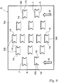
- the displacement absorbing member 5 of FIG. 8 includes spring functional parts 5B that are disposed at different intervals between adjacent spring functional parts 5B according to the location in a cooling fluid channel F.
- the displacement absorbing member 5 includes spring functional parts 5B with cutouts 16 with a triangular cross-section as the channel flow resistance reducing means.
- the spring functional parts 5B are arranged in five rows in the direction transverse to the flow direction of a cooling fluid (shown by the arrows B), in which the intervals between spring functional parts 5B in the respective rows are gradually increased with the location from the center row to the outer rows. Accordingly, in the displacement absorbing member 5, the number of spring functional parts 5 is gradually decreased with the location from the center row to the outer side rows.
- this displacement absorbing member 5 locally changes the channel flow resistance of the cooling fluid by the spring functional parts 5B disposed at different intervals between adjacent spring functional parts 5B according to the location in the cooling fluid channel F. Therefore, the distribution of the cooling fluid can be adjusted.
- the fuel cell stack FS with this displacement absorbing member 5 achieves both of the reduction of the pressure loss in the cooling fluid channel F by means of the displacement absorbing member 5 and the adequate spring function of the displacement absorbing member 5 and the adequate electricity conducting function of the displacement absorbing member 5 as a connector.
- the displacement absorbing member 15 of FIG. 9 is constituted by a thin metal plate formed in a corrugated shape.
- the displacement absorbing member 15 is configured such that the contacting parts in contact with the separators 2 moves in the in-plane direction according to a deformation in the thickness direction. That is, the displacement absorbing member 15 is in contact with the separators 2 of adjacent single cells at the apexes of the corrugation, as shown in FIG. 9 (A) .
- the displacement absorbing member 15 is collapsed and deformed from the shape shown by the solid line to the shape shown by the virtual line so as to be extended in the direction of the corrugation by the length L.
- the contacting parts of the displacement absorbing member 15 in contact with the separators 2 moves in the in-plane direction.
- the displacement absorbing member 15 is disposed so that the moving direction of the contacting parts corresponds to the flow direction of cooling fluid, which is the direction of the arrow B in FIG. 9 . Further, as illustrated in FIG. 9 (B) , the displacement absorbing member 15 has a plurality of round openings 46 at selected locations. In the displacement absorbing member 15 according to this embodiment, the openings 46 correspond to the channel flow resistance reducing means that reduces the channel flow resistance by decreasing the projected area of the displacement absorbing member 15 projected in the flow direction of the cooling fluid in an arbitrary location in the flow direction.
- the displacement absorbing member 15 absorbs the resultant displacement in the stacking direction caused by internal thermal expansion of single cells C or swelling of membrane electrode assemblies. Since the displacement absorbing member 15 has the openings 46 as the channel flow resistance reducing means, it allows smooth flow of the cooling fluid.
- the fuel cell stack reduces the pressure loss of the cooling fluid channel F while retaining the spring characteristics of the displacement absorbing member 15 at a good level, and thereby achieves both of the reduction of the pressure loss in the cooling fluid channel F by means of the displacement absorbing member 5 and the adequate spring function of the displacement absorbing member 5 and the adequate electricity conducting function of the displacement absorbing member 5 as a connector. Furthermore, since the openings 46 are composed of circles, i.e. curved lines, the openings 46 prevent vortex flow at the downstream side thereof. Therefore, the displacement absorbing member 15 can further reduce the pressure loss in the cooling fluid channel.
- the configuration of the fuel cell stack according to the present invention is defined in the appended claims.
- the configurations of the above-described embodiments can be combined with each other.
- a change may be made in the plate thickness and elasticity of the displacement absorbing member, the shape, size, number, arrangement and direction with respect to the flowing direction of the cooling fluid of the spring functional parts of the displacement absorbing member, and the shape, size, number and arrangement of the cutouts or openings, which are the channel flow resistance reducing means.
- the fuel cell stack in which the displacement absorbing member is disposed in the cooling fluid channel between the stacked single cells, can achieve both of the reduction of the pressure loss in the cooling fluid channel by means of the displacement absorbing member and the adequate spring function of the displacement absorbing member and the adequate electricity conducting function of the displacement absorbing member as a connector.
Description
- The present invention relates to a fuel cell such as a polymer electrolyte fuel cell (PEFC), particularly to a fuel cell stack that has a cooling fluid channel formed between stacked single cells.
- One of such fuel cell stacks is described in, for example,
Patent Document 1 where it is referred to as a fuel cell. The fuel cell described inPatent Document 1 is composed of a stacked plurality of fuel cells. Each of the fuel cells includes a hydrogen electrode with an uneven cross-section and an oxygen electrode including an drain layer with an uneven cross-section, which are disposed on opposite sides of an MEA (membrane electrode assembly), and further includes flat plate separators disposed on the outer sides of the hydrogen electrode and the oxygen electrodes to form a hydrogen channel and an oxygen channel in the respective interfaces with the electrodes. Furthermore, the fuel cell includes a coolant channel portion at the side of the oxygen electrode. - The coolant channel portion includes two flat plate separators and a pre-compressed plate interposed between them, wherein a coolant channel is formed between the two flat plate separators. The pre-compressed plate has a corrugated cross-sectional shape so as to be elastically deformable in the thickness direction (stacking direction of the stack). The pre-compressed plate distributes a load that is locally generated due to a shape error of the components of the fuel cell so as to apply a uniform load to each component.
- Other examples of fuel cell stacks or parts of fuel cell stack are disclosed in Patent Documents 2 - 7.
-
- Patent Document 1: Japanese Patent No.
4432518 - Patent Document 2: Japanese Patent Application No.
2012 248460 A - Patent Document 3:
US Patent Application No. 2009/136805 A1 - Patent Document 4: Japanese Patent Application No.
2012 059383 A - Patent Document 5: European Patent Application No.
1 982 375 A2 - Patent Document 6: European Patent Application No.
2 846 385 A1 - Patent Document 7: European Patent Application No.
2 843 741 A1 - However, in the above-described conventional fuel cell stack, while the coolant channel causes a large pressure loss due to the decompressed plate disposed therein, the decompressed plate essentially requires certain spring characteristics. Accordingly, a problem with the conventional fuel cell stack is that it is difficult to decrease the pressure loss of the channel while maintaining the spring characteristics of the decompressed plate, and it has been desired to solve the problem in the prior art.
- The present invention was made in view of the above-described circumstances, and an object thereof is to provide a fuel cell stack that has a coolant channel formed between stacked single cells and includes a displacement absorbing member disposed in the coolant channel, wherein the pressure loss in the coolant channel can be reduced while retaining the spring characteristics of the displacement absorbing member.
- The fuel cell stack of the present invention is defined in appended
claim 1. It includes, inter alia, a stacked plurality of single cells, each including a membrane electrode assembly and a pair of separators sandwiching the membrane electrode assembly, wherein a cooling fluid channel where a cooling fluid flows is formed between adjacent single cells, and the fuel cell stack further includes a displacement absorbing member disposed in the cooling fluid channel to absorb a displacement between the plurality of single cells. Furthermore, in the fuel cell stack, the displacement absorbing member includes a channel flow resistance reducing means that reduces the channel flow resistance of the cooling fluid channel against the cooling fluid. - In the fuel cell stack according to the present invention, which includes the cooling fluid channel formed between the stacked single cells and the displacement absorbing member disposed in the cooling fluid channel, the pressure loss in the cooling fluid channel can be reduced while maintaining the spring characteristics of the displacement absorbing member.
-
-
FIG. 1 are (A) an exploded perspective view of a fuel cell stack, and (B) a perspective view of the assembled fuel cell stack. -
FIG. 2 are (A) an exploded plan view of a single cell of the fuel cell stack ofFIG. 1 , and (B) a plan view of the assembled single cell. -
FIG. 3 is a cross sectional view taken along line A-A inFIG. 2 (B) . -
FIG. 4 are (A) a perspective view of a displacement absorbing member, and (B) a cross sectional view around a spring functional part thereof. -
FIG. 5 are (A) to (E) front views of spring functional parts according to other embodiments, viewing from the flowing direction of cooling fluid. -
FIG. 6 are (A) a perspective view of a spring functional group according to yet another embodiment before lancing, and (B) a perspective view and (C) a cross sectional view thereof after lancing. -
FIG. 7 is a front view of a displacement absorbing member according to yet another embodiment, viewing from the flowing direction of cooling fluid. -
FIG. 8 is a plan view of a displacement absorbing member according to yet another embodiment. -
FIG. 9 are (A) a cross sectional view and (B) a perspective view of a displacement absorbing member according to yet another embodiment. - Hereinafter, a fuel cell stack according to a first embodiment will be described based on the drawings. The fuel cell stack according to this embodiment, which includes a stacked plurality of solid polymer electrolyte single cells, is used for, for example, a power source of vehicles such as electric cars.
- The fuel cell stack FS of
FIG. 1 (A) includes a plurality of rectangular plate single cells C that are stacked together to form a stack S, anend plate 56A provided on one end in the stacking direction (right end inFIG. 1 ) of the stack S via acurrent collector 54A and aspacer 55, and anend plate 56B provided on the other end via acurrent collector 54B. The fuel cell stack FS further includesfastening plates FIG. 1 ), and reinforcingplates - In the fuel cell stack FS, the
fastening plate reinforcing plates end plates FIG. 1 (B) in which the stack S is restrained and pressed in the stacking direction so that a predetermined contact pressure is applied to each of the single cells C. With this structure, the gas sealing property and the electrical conductivity are maintained at a high level - As illustrated in
FIG. 2 , each of the single cells C includes amembrane electrode assembly 1 with aframe 51 along the periphery thereof, a pair ofseparators frame 51 and themembrane electrode assembly 1. The single cells C are configured such that gas flows in the opposite directions between the gas channels (GC, GA). The cathode gas is oxygen-containing gas (air), and the anode gas is hydrogen-containing gas. - The
membrane electrode assembly 1, which is generally referred to as an MEA (membrane electrode assembly), includes anelectrolyte layer 11 of a solid polymer, and acathode layer 12 and ananode layer 13 sandwiching theelectrolyte layer 11 as illustrated inFIG. 3 . Although not shown in detail in the figure, each of theelectrode layers electrolyte layer 11 and a gas diffusion layer disposed on the outer side thereof. - The
frame 51 is integrally formed with themembrane electrode assembly 1 by resin molding (e.g. injection molding) such that themembrane electrode assembly 1 is positioned in the center. Theframe 51 has manifold holes H1 to H3 and H4 to H6 that are arranged such that each short side has three manifold holes. Areas between the manifold holes and themembrane electrode assembly 1 serve as diffuser parts D. Theframe 51 and theseparators - Further, the
frame 51 has a plurality ofround protrusions 52 arranged in a matrix on both surfaces within the diffuser parts D as illustrated inFIG. 2 . When the single cells C deform in the thickness direction due to a change of themembrane electrode assembly 1 over time or the like, theprotrusions 52 come in contact with theseparators - The
separators 2 are metal plates in which one plate has reversed faces to those of the other plate. For example, theseparators 2 are made of stainless steel and may be formed in any suitable shape by press working. The illustratedseparators 2 are formed in an uneven cross-sectional shape at least in the center part corresponding to themembrane electrode assembly 1. - The uneven cross-sectional shape of each of the
separators 2 continues in the length direction as illustrated inFIG. 2 . The apexes of the corrugation are in contact with themembrane electrode assembly 1 while the bottoms of the corrugation form the cathode and anode gas channels (GC, GA) between the bottoms and themembrane electrode assembly 1 as illustrated in the cross sectional view ofFIG. 3 . Further, each of theseparators 2 has manifold holes H1 to H6 at both ends, which are similar to the manifold holes H1 to H6 of theframe 51. - In the
frame 51 and theseparators FIG. 2 are configured respectively to supply anode gas (H1), to discharge cooling fluid (H2) and to discharge cathode gas (H3) from the top. These manifold holes are communicated with corresponding manifold holes in the stacking direction to form respective channels. The manifold holes H4 to H6 on the right inFIG. 2 are configured respectively to supply the cathode gas (H4), to supply the cooling fluid (H5) and to discharge the anode gas (H6) from the top. These manifold holes are communicated with corresponding manifold holes in the stacking direction to form respective channels. - Further, as illustrated in
FIG. 2 , each of the single cells C includes a gas sealers SL provided between theframe 51 and theseparators 2 at the edge part thereof and around the manifold holes H1 to H6. When the plurality of single cells C are stacked, the gas sealer SL is also provided between the single cells C, i.e. betweenadjacent separators 2. The gas sealers SL airtightly separate the respective interlayers. Further, the gas sealers SL have openings or are selectively removed in the periphery of the manifold holes H1 to H6 so as to allow the cathode gas, the anode gas and the cooling fluid to flow only within the respective flow areas. - The plurality of single cells C are stacked together to form the fuel cell stack FS. As illustrated in
FIG. 3 , a cooling fluid channel F is formed between adjacent single cells C, and adisplacement absorbing member 5 to absorb a displacement between the single cells C is interposed in the cooling fluid channel F. - In the fuel cell stack FS, the
displacement absorbing member 5 includes a channel flow resistance reducing means that reduces the channel flow resistance of the cooling fluid channel F against the cooling fluid. The channel flow resistance reducing means reduces the channel flow resistance by reducing the projected area of the displacement absorbing means projected in the flowing direction of the cooling fluid at an arbitrary location in the flowing direction or by preventing vortex flow of the cooling fluid, or the like. - In summary, the
displacement absorbing member 5 is configured such that a contacting part in contact with theseparator 2 moves in the in-plane direction according to a deformation in the thickness direction. As described above withFIG. 2 andFIG. 3 , in the fuel cell stack FS, the surfaces of theseparators 2 facing the cooling fluid channel F have an uneven cross-sectional shape that continues in the flow direction of the cooling fluid. That is, the continuing direction corresponds to the flow direction of the cooling fluid. Specifically, the flow direction of the cooling fluid corresponds to the horizontal direction inFIG. 2 or the direction perpendicular to the paper plane inFIG. 3 . In the fuel cell stack FS, thedisplacement absorbing member 5 is disposed so that the moving direction of the contacting part corresponds to the flow direction of the cooling fluid. - The
displacement absorbing member 5 of this embodiment is made of a thin metal plate. As illustrated in the partial view ofFIG. 4 (A) , a number of springfunctional parts 5B are arranged in a matrix on one surface of abase plate 5A. Thedisplacement absorbing member 5 is electrically conductive and thereby also has a function as a connector to electrically connect the single cells C to each other as well as the displacement absorbing function. Each of the springfunctional parts 5B has a tongue-shaped cantilever structure with a fixed end K on thebase plate 5A and a free tip end J. While the springfunctional parts 5B of this embodiment have a rectangular shape, the shape is not particularly limited. - The
displacement absorbing member 5 is configured such that the contacting parts in contact with theseparator 2 move in the in-plane direction according to a deformation in the thickness direction. That is, as illustrated inFIG. 4 (B) , thedisplacement absorbing member 5 is provided such that thebase plate 5A is in contact with theseparator 2 of a single cell at one side (lower side inFIG. 4 ) while the free ends J of the springfunctional parts 5B are in contact with theseparator 2 of a single cell at the other side. In thedisplacement absorbing member 5, when the gap between theseparators functional parts 5B swings from the position illustrated by the solid line to the position illustrated by the virtual line (or the reverse direction). As the inclination angle of the springfunctional parts 5B changes, the contacting parts of the free ends J in contact with theother separator 2 move in the in-plane direction by the distance L - Further, the
displacement absorbing member 5 is disposed so that the moving direction of the contacting parts corresponds to the flow direction of the cooling fluid, i.e. the direction indicated by the arrow B inFIG. 4 . In this regard, the free ends J of the springfunctional parts 5B head downstream in the flow direction of the cooling fluid. The springfunctional parts 5B have a flat cross-sectional shape inFIG. 4 , but they may have a suitable cross-sectional shape. For example, when the free ends J are curved so that the contacting parts in contact with theseparator 2 are constituted of curved surfaces, they can slide more smoothly with respect to theseparator 2. - Furthermore, in the
displacement absorbing member 5, the springfunctional parts 5B are formed by lancing the base plate A. Accordingly, thebase plate 5A hasopenings 5C corresponding to the springfunctional parts 5B. Thedisplacement absorbing member 5 with such configuration can be easily produced from a single sheet by means of press working or the like. - In the above-described
displacement absorbing member 5,pathways 6 between the springfunctional parts 5B arranged in the direction transverse to the flow direction of the cooling fluid (direction indicated by the arrow B) correspond to the channel flow resistance reducing means. That is, thepathways 6 correspond to a means that reduces the channel flow resistance by reducing the projected area of thedisplacement absorbing means 5 projected in the flow direction of the cooling fluid in an arbitrary location in the flow direction. In this embodiment, since the springfunctional parts 5B are arranged in a matrix, thepathways 6 continue in the flow direction of the cooling fluid. - The fuel cell stack FS supplies the anode gas and the cathode gas to the
membrane electrode assembly 1 through the gas channels GC, GA while allowing the cooling fluid to flow through the cooling fluid channel F between adjacent single cells C, so as to generate electric energy by an electrochemical reaction. In the event of internal thermal expansion of the single cells C or swelling of themembrane electrode assembly 1, thedisplacement absorbing member 5 absorbs the resultant displacement in the stacking direction. - In the fuel cell stack FS, the
displacement absorbing member 5 is interposed in the cooling fluid channel. However, since thedisplacement absorbing member 5 has thepathways 6 as the channel flow resistance reducing means for the cooling fluid channel F, the cooling fluid flows smoothly. As a result, the fuel cell stack FS can reduce the pressure loss in the cooling fluid channel F while maintaining the spring characteristics of thedisplacement absorbing member 5 at a good level, which eventually enables reducing the size and weight of a pump for the cooling fluid. - Furthermore, the fuel cell stack FS employs the means (pathways 6) that reduces the channel flow resistance by reducing the projected area of the
displacement absorbing member 5 projected in the flow direction of the cooling fluid at an arbitrary location in the flow direction. Therefore, with such a simple configuration, smooth flow of the cooling fluid can be achieved, and the pressure loss in the cooling fluid channel F is reduced. - Furthermore, in the fuel cell stack FS, the surfaces of the
separators 2 facing the cooling fluid channel F have an uneven cross-sectional shape that continues in the flow direction of the cooling fluid, thedisplacement absorbing member 5 includes the contacting portions in contact with theseparator 2 configured to move in the in-plane direction according to a deformation in the thickness direction, and thedisplacement absorbing member 5 is disposed so that the moving direction of the contacting portions corresponds to the flow direction of the cooling fluid. Therefore, in the fuel cell stack FS, thedisplacement absorbing member 5 is prevented from being partly stuck in the recesses of theseparators 2 when it moves in the in-plane direction, and the contact between them is maintained in a good condition. In addition, both surfaces of theseparators 2 can be effectively utilized respectively as the gas channel CG (CA) and the cooling fluid channel F. This can reduce the thickness of the single cells C and thus reduce the size of the fuel cell stack FS. - Furthermore, in the fuel cell stack FS, the
displacement absorbing member 5 includes a number of springfunctional parts 5B that are arranged on one surface of thebase plate 5A, and the springfunctional parts 5B have a cantilever structure with the fixed proximal end K fixed on thebase plate 5A and the free tip end J. Therefore, the fuel cell stack FS can adequately absorb a displacement in the thickness direction with such a simple structure and can be therefore produced at a low cost. Further, in thedisplacement absorbing member 5, the springfunctional parts 5B have a simple shape and can be easily formed at short pitches to decrease the spring stiffness. With such decreased spring stiffness, thedisplacement absorbing member 5 exhibits spring characteristics that causes small load change in response to a displacement. Even when thedisplacement absorbing member 5 is deteriorated due to displacements in the compressing direction during operation or time degradation, the deterioration causes small change in surface pressure, and the electrical contact resistance between components is stable. - Furthermore, in the fuel cell stack FS, the spring
functional parts 5B of thedisplacement absorbing member 5 are formed by lancing thebase plate 5A. Therefore, as described above, thedisplacement absorbing member 5 can be easily formed from a single sheet by press working. The lacing for the springfunctional parts 5B forms theopenings 5C in thedisplacement absorbing member 5, and the cooling fluid can flow in the vertical direction through theopenings 5C. Therefore, this can improve the cooling effect in addition to the reduction of the pressure loss. - Furthermore, in the fuel cell stack FS, the
displacement absorbing member 5 is disposed so that the free ends J of the springfunctional parts 5B head downstream in the flow direction of the cooling fluid. The springfunctional parts 5B inclined toward the flow direction of the cooling fluid prevent vortex flow in the downstream side of the springfunctional parts 5B. This can further reduce the pressure loss in the cooling fluid channel F. - In a fuel cell stack FS in which a
displacement absorbing member 5 is disposed in a cooling fluid channel F between stacked single cells C, the pressure loss in the cooling fluid channel F due to thedisplacement absorbing member 5 is contradictory to the spring function of thedisplacement absorbing member 5 and the electricity conducting function of thedisplacement absorbing member 5, as a connector between the single cells C. That is, in order to reduce the pressure loss in the cooling fluid channel F, thedisplacement absorbing member 5 can be formed in a shape and size that can minimize the resistance. However, such a shape and size degrade the spring function and the electricity conducting function of thedisplacement absorbing member 5. - To cope with the problem, in the fuel cell stack FS according to the above-described embodiment, the
displacement absorbing member 5 includes thepathways 6 as the channel flow resistance reducing means so that it has a reduced projected area projected in the flow direction of the cooling fluid in an arbitrary location in the flow direction. Furthermore, in thedisplacement absorbing member 5, the moving direction of the contacting portions in contact with theseparator 2, which move according to a deformation in the thickness direction, corresponds to the flow direction of the cooling fluid, the springfunctional parts 5B has a cantilever structure, the springfunctional parts 5B are formed by lancing thebase plate 5A so that theopenings 5C are formed therein, and the springfunctional parts 5B are disposed so that the free ends J head downstream in the flow direction of the cooling fluid. - Therefore, the fuel cell stack FS, in which the
displacement absorbing member 5 is disposed in the cooling fluid channel F between the stacked single cells C, achieves both of the reduction in pressure loss in the cooling fluid channel F by means of thedisplacement absorbing member 5 and the adequate spring function and the adequate electricity conducting function as a connector of thedisplacement absorbing member 5. -
FIG. 5 illustrates displacement absorbing members according to other embodiments, which are a component of the fuel cells stack.FIG. 5 illustrate cross-sections viewing in the flow direction of a cooling fluid from the upstream to the downstream. The same reference signs are denoted to the same components as those of the previous embodiment, and the detail description thereof is omitted. - The
displacement absorbing members 5 ofFIG. 5 (A) to FIG. 5 (E) include abase plate 5A and cantilever springfunctional parts 5B disposed on one surface of thebase plate 5A. Thedisplacement absorbing members 5 include a channel flow resistance reducing means that reduces the channel flow resistance by reducing the projected area of thedisplacement absorbing members 5 projected in the flow direction of the cooling fluid in an arbitrary location in the flow direction. To be more specific, the channel flow resistance reducing means of these embodiments is constituted by at least either openings or cutouts formed in the springfunctional parts 5B within the areas from free ends J to fixed ends K. - The cutouts of these embodiments refer to portions that are cut out from basic rectangular spring
functional parts 5B as illustrated inFIG. 4 . That is, the cutouts can be formed by removing a part of the springfunctional parts 5B after forming them, or the cutouts can be formed simultaneously with forming the springfunctional parts 5B by lancing. - The spring
functional part 5B ofFIG. 5 (A) or FIG. 5 (B) has a width that decreases with the location from the fixed end K toward the free end J. That is, the springfunctional part 5B ofFIG. 5 (A) hasrectangular cutouts functional part 5B ofFIG. 5 (B) hastriangular cutouts - The
displacement absorbing members 5 with the above-described springfunctional parts 5B can reduce the pressure loss in the cooling fluid channel F by thecutouts 16 expanding the cooling fluid channel F to allow smoother flow of the cooling fluid. Further, the springfunctional parts 5B have a width that decreases with the location from the fixed ends K to the free ends J. Therefore, in addition to the reduction in pressure loss, thedisplacement absorbing members 5 can retain its spring characteristics at a good level since the sufficient width of the springfunctional parts 5B is secured at the fixed ends K and a sharp change in strength of the spring material can be thereby prevented. - The spring
functional parts 5B ofFIG. 5 (C) and FIG. 5 (D) include the channel flow resistance reducing means provided between the free end J and the fixed end K within the area from the free end J to the fixed end K. In short, the channel flow resistance reducing means is provided in the middle area excluding the free end J and the fixed end K. The springfunctional part 5B ofFIG. 5 (C) includestriangular cutouts functional part 5B ofFIG. 5 (D) includesrectangular opening 26 in the center thereof. - The
displacement absorbing member 5 with the above-described springfunctional parts 5B can reduce the pressure loss in the cooling fluid channel F by thecutouts 16 or theopenings 26 expanding the cooling fluid channel F to allow smoother flow of the cooling fluid. Further, since thecutouts 16 or theopenings 26 are formed between the free ends J and the fixed ends K in the springfunctional parts 5B, thedisplacement absorbing member 5 can secure a sufficient contact area between the free ends J of the springfunctional parts 5B and aseparator 2. Therefore, thedisplacement absorbing member 5 can reduce the pressure loss in the cooling fluid channel F without affecting the electrical conductivity. - The spring
functional part 5B ofFIG. 5 (E) includes a channel flow resistance reducing means provided between the free end J and the fixed end K. That is, the springfunctional part 5B includesU-shaped cutouts cutouts 36 are composed of only curved lines. Thesecutouts 36 correspond to the channel flow resistance reducing means that reduces the channel flow resistance by preventing vortex flow of the cooling fluid. - As with the previous embodiment, the
displacement absorbing member 5 with the above-described springfunctional parts 5B can secure a sufficient contact area between the free ends J of the springfunctional parts 5B and aseparator 2 so that it can reduce the pressure loss in the cooling fluid channel F without affecting the electrical conductivity. Further, thecutouts 36 composed of a curved line prevent vortex flow at the downstream side of the springfunctional parts 5B, which can further reduce the pressure loss. In particular, when the free ends J of the springfunctional parts 5B are arranged to face toward the downstream in the flow direction of the cooling fluid as illustrated inFIG. 4 (B) , the curved lines of thecutouts 36 follow the flow direction of the cooling fluid. This can prevent vortex flow more effectively. - All of the
displacement absorbing members 5 that respectively include the springfunctional parts 5B ofFIG. 5 (A) to FIG. 5 (E) can be readily produced from a single sheet material by press molding. Further, as the channel flow resistance reducing means, thesedisplacement absorbing members 5 includecutouts openings 26 as well as thepathways 6 as described in the previous embodiment. Therefore, their functions are combined with each other to provide further reduction of the pressure loss in the cooling fluid channel F. - In the fuel cell stack of the above-described embodiments, the spring
functional parts 5B of thedisplacement absorbing member 5 have a width that decreases with the location from the fixed ends K to the free ends J, or each of the springfunctional parts 5B includes thecutouts openings 26 over the area from the free end J to the fixed end K or between the free end J and the fixed end K, or thecutouts opening 2 is composed of a curved line. Therefore, as with the previous embodiment, the fuel cell stack achieves both of the reduction of the pressure loss in the cooling fluid channel F by means of thedisplacement absorbing member 5 and the adequate spring function of thedisplacement absorbing member 5 and the adequate electricity conducting function of thedisplacement absorbing member 5 as a connector. -
FIG. 6 illustrates a displacement absorbing member according to yet another embodiment, which is a component of the fuel cell stack. The illustrateddisplacement absorbing member 5 includes springfunctional parts 5B that are formed by lancing abase plate 5A. In particular, as illustrated inFIG. 6 (A) ,blank areas 5D are provided around the springfunctional parts 5B, which are formed by lancing thebase plate 5A. - The
blank areas 5D can be formed by punching at the time of press-molding thedisplacement absorbing member 5. Accordingly, as illustrated inFIG. 6 (B) , thedisplacement absorbing member 5 hasopenings 5C (including the blank areas) that are slightly larger than the springfunctional parts 5B. - The
displacement absorbing member 5 with the above-described springfunctional parts 5B allows smoother flow of the cooling fluid through theopenings 5C. That is, in the previously-describeddisplacement absorbing member 5 with the springfunctional parts 5B ofFIG. 4 , the cooling fluid flows up and down through theopenings 5C. However, since the width of the springfunctional parts 5B is approximately equal to the width of theopenings 5C, the cooling fluid goes around the springfunctional parts 5B to flow into theopenings 5C. - In contrast, in the
displacement absorbing member 5 according to this embodiment, since the width of theopenings 5C are greater than the width of the springfunctional parts 5B by the width of theblank areas 5D, the cooling fluid readily flow into theopenings 5C as illustrated inFIG. 6 (C) . Therefore, thedisplacement absorbing member 5 further reduces the pressure loss in the cooling fluid channel F while retaining its spring characteristics at a good level. As with the previous embodiments, the fuel cell stack with thisdisplacement absorbing member 5 achieves both of the reduction of the pressure loss in the cooling fluid channel F by means of thedisplacement absorbing member 5 and the adequate spring function of thedisplacement absorbing member 5 and the adequate electricity conducting function of thedisplacement absorbing member 5 as a connector. - The
displacement absorbing member 5 ofFIG. 7 includes springfunctional parts 5B with different shapes according to the location in a cooling fluid channel F. In particular, the springfunctional parts 5B are disposed so that the channel size is decreased in both side areas of the cooling fluid channel F along the flow direction of the cooling fluid (direction perpendicular to the paper plane inFIG. 7 ). - Specifically, the
displacement absorbing member 5 includes rectangular springfunctional parts 5B that are arranged on abase plate 5A, in which some of the springfunctional parts 5B havecutouts 16 with a triangular cross-section as the channel flow resistance reducing means while the other springfunctional parts 5B have no cutout. - Further, in the illustrated
displacement absorbing member 5, the springfunctional parts 5B are arranged in seven rows in the direction transverse to the flow direction of the cooling fluid (horizontal direction inFIG. 7 ). The springfunctional parts 5B with thelargest cutouts 16A are disposed in the center, the springfunctional parts 5B withcutouts 16B smaller than the center cutouts are disposed in the two rows on both sides thereof, the springfunctional parts 5B with furthersmaller cutouts 16C are disposed in the two rows on both of the further outer sides thereof, and the springfunctional parts 5B with no cutout are disposed in the two rows on the outermost sides. - As described above, the size of the cutouts is decreased with the location from the center toward the outer sides of the cooling fluid channel F, and no cutout is formed in the outermost areas. In this way, the
displacement absorbing member 5 decreases the channel size in both side areas of the cooling fluid channel F along the flow direction of the cooling fluid. - The
displacement absorbing member 5 can adjust the distribution of the cooling fluid by locally changing the channel flow resistance of the cooling fluid by means of the springfunctional parts 5B with different shapes disposed according to the location in the cooling fluid channel F. Further, thedisplacement absorbing member 5 exhibits low channel flow resistance in the center area when the springfunctional parts 5B are disposed as illustrated in the figure so as to decrease the channel size of the cooling fluid channel F in the side areas along the flow direction of the cooling fluid. Accordingly, the cooling fluid is more likely to flow in the center area. - Since single cells C have a power generating area of the
membrane electrode assembly 1 in the center part as illustrated inFIG. 2 , the temperature becomes high in the center part during operation. To cope with the high temperature, thedisplacement absorbing member 5 concentrates the flow of the cooling fluid to the center area so that it can efficiently cool the single cells C. This can also contribute to improving the power generating performance. In this way, as with the previous embodiments, the fuel cell stack FS achieves both of the reduction of the pressure loss in the cooling fluid channel F by means of thedisplacement absorbing member 5 and the adequate spring function of thedisplacement absorbing member 5 and the adequate electricity conducting function of thedisplacement absorbing member 5 as a connector. - The
displacement absorbing member 5 ofFIG. 8 includes springfunctional parts 5B that are disposed at different intervals between adjacent springfunctional parts 5B according to the location in a cooling fluid channel F. As with the previous embodiments, thedisplacement absorbing member 5 includes springfunctional parts 5B withcutouts 16 with a triangular cross-section as the channel flow resistance reducing means. - In the illustrated
displacement absorbing member 5, the springfunctional parts 5B are arranged in five rows in the direction transverse to the flow direction of a cooling fluid (shown by the arrows B), in which the intervals between springfunctional parts 5B in the respective rows are gradually increased with the location from the center row to the outer rows. Accordingly, in thedisplacement absorbing member 5, the number of springfunctional parts 5 is gradually decreased with the location from the center row to the outer side rows. - As with the previous embodiment, this
displacement absorbing member 5 locally changes the channel flow resistance of the cooling fluid by the springfunctional parts 5B disposed at different intervals between adjacent springfunctional parts 5B according to the location in the cooling fluid channel F. Therefore, the distribution of the cooling fluid can be adjusted. As with the previous embodiments, the fuel cell stack FS with thisdisplacement absorbing member 5 achieves both of the reduction of the pressure loss in the cooling fluid channel F by means of thedisplacement absorbing member 5 and the adequate spring function of thedisplacement absorbing member 5 and the adequate electricity conducting function of thedisplacement absorbing member 5 as a connector. - The
displacement absorbing member 15 ofFIG. 9 is constituted by a thin metal plate formed in a corrugated shape. Thedisplacement absorbing member 15 is configured such that the contacting parts in contact with theseparators 2 moves in the in-plane direction according to a deformation in the thickness direction. That is, thedisplacement absorbing member 15 is in contact with theseparators 2 of adjacent single cells at the apexes of the corrugation, as shown inFIG. 9 (A) . When the gap between theseparators displacement absorbing member 15 is collapsed and deformed from the shape shown by the solid line to the shape shown by the virtual line so as to be extended in the direction of the corrugation by the length L. As a result, the contacting parts of thedisplacement absorbing member 15 in contact with theseparators 2 moves in the in-plane direction. - The
displacement absorbing member 15 is disposed so that the moving direction of the contacting parts corresponds to the flow direction of cooling fluid, which is the direction of the arrow B inFIG. 9 . Further, as illustrated inFIG. 9 (B) , thedisplacement absorbing member 15 has a plurality ofround openings 46 at selected locations. In thedisplacement absorbing member 15 according to this embodiment, theopenings 46 correspond to the channel flow resistance reducing means that reduces the channel flow resistance by decreasing the projected area of thedisplacement absorbing member 15 projected in the flow direction of the cooling fluid in an arbitrary location in the flow direction. - As with the previous embodiments, in the fuel cell stack with this
displacement absorbing member 15, thedisplacement absorbing member 15 absorbs the resultant displacement in the stacking direction caused by internal thermal expansion of single cells C or swelling of membrane electrode assemblies. Since thedisplacement absorbing member 15 has theopenings 46 as the channel flow resistance reducing means, it allows smooth flow of the cooling fluid. - In this way, the fuel cell stack reduces the pressure loss of the cooling fluid channel F while retaining the spring characteristics of the
displacement absorbing member 15 at a good level, and thereby achieves both of the reduction of the pressure loss in the cooling fluid channel F by means of thedisplacement absorbing member 5 and the adequate spring function of thedisplacement absorbing member 5 and the adequate electricity conducting function of thedisplacement absorbing member 5 as a connector. Furthermore, since theopenings 46 are composed of circles, i.e. curved lines, theopenings 46 prevent vortex flow at the downstream side thereof. Therefore, thedisplacement absorbing member 15 can further reduce the pressure loss in the cooling fluid channel. - The configuration of the fuel cell stack according to the present invention is defined in the appended claims. In the fuel cell stack of the present invention, the configurations of the above-described embodiments can be combined with each other. Further, a change may be made in the plate thickness and elasticity of the displacement absorbing member, the shape, size, number, arrangement and direction with respect to the flowing direction of the cooling fluid of the spring functional parts of the displacement absorbing member, and the shape, size, number and arrangement of the cutouts or openings, which are the channel flow resistance reducing means.
- With such configuration, the fuel cell stack, in which the displacement absorbing member is disposed in the cooling fluid channel between the stacked single cells, can achieve both of the reduction of the pressure loss in the cooling fluid channel by means of the displacement absorbing member and the adequate spring function of the displacement absorbing member and the adequate electricity conducting function of the displacement absorbing member as a connector.
-
- C
- Single cell
- F
- Cooling fluid channel
- FS
- Fuel cell stack
- 1
- Membrane electrode assembly
- 2
- Separator
- 5, 15
- Displacement absorbing member
- 5A
- Base plate
- 5B
- Spring functional part
- 5C
- Opening
- 5D
- Blank part
- 6
- Channel (channel flow resistance reducing means)
- 16, 36
- Cutout (channel flow resistance reducing means)
- 26, 46
- Opening (channel flow resistance reducing means)
- J
- Free end of spring functional part
- K
- Fixed end of spring functional part
Claims (12)
- A fuel cell stack, comprising:a stacked plurality of single cells (C), each of the single cells (C) comprising a membrane electrode assembly (1) and a pair of separators (2) sandwiching the membrane electrode assembly therebetween,wherein a cooling fluid channel (F) where a cooling fluid flows is formed between adjacent single cells, and the fuel cell stack (FS) further comprises a displacement absorbing member (5) disposed in the cooling fluid channel (F) to absorb a displacement between the single cells,wherein the displacement absorbing member (5) comprises a channel flow resistance reducing means to reduce a channel flow resistance of the cooling fluid channel (F) against the cooling fluid by preventing vortex flow of the cooling fluid,wherein the displacement absorbing member (5) comprises a base plate (5A) and a number of spring functional parts (5B) arranged on one surface of the base plate (5A), and the spring functional parts (5B) have a cantilever structure comprising a fixed proximal end (K) fixed on the base plate (5A) and a free tip end (J), the displacement absorbing member (5) being disposed so that the free tip end (J) of spring functional parts (5B) faces toward a downstream of the flow direction of the cooling fluid,characterized in that the channel flow resistance reducing means is constituted by at least either an opening (26) or a cutout (16, 36) formed in the spring functional parts (5B) between the free tip end (J) and the fixed proximal end (K) thereof,wherein the cutouts (16, 36) are formed by removing a part of the spring functional parts (5B) after forming them, or formed simultaneously with forming the spring functional parts (5B) by lancing the base plate (5A), andwherein the displacement absorbing member (5) comprises spring functional parts (5B) that have different shapes according to a location in the cooling fluid channel (F).
- The fuel cell stack according to claim 1,
wherein the channel flow resistance reducing means is configured to reduce the channel flow resistance by reducing a projected area of the displacement absorbing member (5) projected in a flow direction of the cooling fluid in an arbitrary location in the flow direction. - The fuel cell stack according to claim 1 or 2,
wherein a surface of the separators (2) facing the cooling fluid channel (F) has an uneven cross-sectional shape that continues in the flow direction of the cooling fluid, and
the displacement absorbing member (5) is configured such that a contacting part in contact with a separator (2) moves in an in-plane direction according to a deformation in a thickness direction, and is disposed so that a moving direction of the contacting part corresponds to the flow direction of the cooling fluid. - The fuel cell stack according to any one of claims 1 to 3,
wherein the spring functional parts (5B) are formed by lancing the base plate (5A). - The fuel cell stack according to claim 4,
wherein the spring functional parts (5B) are formed by lancing the base plate (5A), in which blank areas are formed along a periphery of the spring functional parts. - The fuel cell stack according to any one of claims 1 to 5,
wherein the channel flow resistance reducing means is formed between the free tip end (J) and the fixed proximal end (K) of the spring functional parts (5B). - The fuel cell stack according to any one of claims 1 to 6,
wherein the spring functional parts (5B) has a width that decreases with a location from the fixed proximal end (K) to the free tip end (J). - The fuel cell stack according to any one of claims 1 to 7,
wherein the opening or the cutout (36) as the channel flow resistance reducing means are composed of a curved line. - The fuel cell stack according to any one of claims 1 to 8,
wherein the displacement absorbing member (5) comprises the spring functional parts (5B) that are disposed so that a channel size of the cooling fluid channel (F) is decreased in both side areas thereof in the flow direction of the cooling fluid. - The fuel cell stack according to claim 9, wherein the channel flow resistance reducing means is constituted by cutouts (16) and wherein the size of the cutouts (16) is decreased with the location from the center toward the outer sides of the cooling fluid channel (F), and no cutout is formed in the outermost areas.
- The fuel cell stack according to any one of claims 1 to 10,
wherein the displacement absorbing member (5) comprises the spring functional parts (5B) that are disposed at different intervals between adjacent spring functional parts according to a location in the cooling fluid channel (F). - The fuel cell stack according to any one of claims 1 to 11,
wherein the channel flow resistance reducing means is a pathway formed between the spring functional parts (5B) of the displacement absorbing member (5).
Applications Claiming Priority (2)
| Application Number | Priority Date | Filing Date | Title |
|---|---|---|---|
| JP2012282310 | 2012-12-26 | ||
| PCT/JP2013/080231 WO2014103528A1 (en) | 2012-12-26 | 2013-11-08 | Fuel cell stack |
Publications (3)
| Publication Number | Publication Date |
|---|---|
| EP2940766A1 EP2940766A1 (en) | 2015-11-04 |
| EP2940766A4 EP2940766A4 (en) | 2016-01-13 |
| EP2940766B1 true EP2940766B1 (en) | 2019-05-01 |
Family
ID=51020627
Family Applications (1)
| Application Number | Title | Priority Date | Filing Date |
|---|---|---|---|
| EP13869338.7A Active EP2940766B1 (en) | 2012-12-26 | 2013-11-08 | Fuel cell stack |
Country Status (6)
| Country | Link |
|---|---|
| US (1) | US10644329B2 (en) |
| EP (1) | EP2940766B1 (en) |
| JP (2) | JP5877596B2 (en) |
| CN (1) | CN104871355B (en) |
| CA (1) | CA2896297C (en) |
| WO (1) | WO2014103528A1 (en) |
Families Citing this family (7)
| Publication number | Priority date | Publication date | Assignee | Title |
|---|---|---|---|---|
| CN107534178B (en) | 2015-05-13 | 2019-01-22 | 日产自动车株式会社 | Fuel cell pack |
| KR102146531B1 (en) * | 2016-07-25 | 2020-08-20 | 주식회사 엘지화학 | Separator, and Fuel cell stack comprising the same |
| WO2019003192A1 (en) * | 2017-06-29 | 2019-01-03 | Versa Power Systems Ltd | Selectively rotated flow field for thermal management in a fuel cell stack |
| JP6854355B2 (en) * | 2017-09-22 | 2021-04-07 | 日産自動車株式会社 | How to manufacture spring members, fuel cell units, fuel cell stacks and fuel cell stacks |
| CN111194498B (en) * | 2017-09-22 | 2023-03-24 | 日产自动车株式会社 | Spring member, fuel cell unit, and fuel cell stack |
| KR20200129912A (en) * | 2019-05-10 | 2020-11-18 | 현대자동차주식회사 | Fuel cell apparatus |
| KR102505477B1 (en) * | 2020-12-17 | 2023-03-06 | 비나텍주식회사 | Separator for fuel cell with impact resistance |
Family Cites Families (19)
| Publication number | Priority date | Publication date | Assignee | Title |
|---|---|---|---|---|
| JPH02160371A (en) * | 1988-12-13 | 1990-06-20 | Toshiba Corp | Gas channel of fuel battery |
| US5776624A (en) * | 1996-12-23 | 1998-07-07 | General Motors Corporation | Brazed bipolar plates for PEM fuel cells |
| US6660419B1 (en) * | 1998-06-30 | 2003-12-09 | Matsushita Electric Industrial Co., Ltd. | Solid polymer electrolyte fuel cell |
| JP3541172B2 (en) * | 2000-10-04 | 2004-07-07 | 本田技研工業株式会社 | Fuel cell and its separator |
| US6815116B2 (en) * | 2001-03-08 | 2004-11-09 | The Regents Of The University Of California | Flexible interconnects for fuel cell stacks |
| JP4813707B2 (en) * | 2001-09-28 | 2011-11-09 | 本田技研工業株式会社 | Fuel cell stack |
| US6924052B2 (en) * | 2002-04-24 | 2005-08-02 | General Motors Corporation | Coolant flow field design for fuel cell stacks |
| JP4432518B2 (en) | 2003-10-27 | 2010-03-17 | トヨタ自動車株式会社 | Fuel cell system |
| JP4992188B2 (en) * | 2005-03-11 | 2012-08-08 | 株式会社エクォス・リサーチ | Separator unit and fuel cell stack |
| JP4899339B2 (en) | 2005-05-16 | 2012-03-21 | トヨタ自動車株式会社 | Fuel cell separator |
| JP4951925B2 (en) * | 2005-10-11 | 2012-06-13 | トヨタ自動車株式会社 | Gas separator for fuel cell and fuel cell |
| IL173539A0 (en) * | 2006-02-05 | 2006-07-05 | Rami Noach | Flow distributor plate |
| JP5224649B2 (en) * | 2006-03-29 | 2013-07-03 | 日本碍子株式会社 | Conductive connecting member and solid oxide fuel cell |
| US20090136805A1 (en) * | 2007-11-23 | 2009-05-28 | Toyota Jidosha Kabushiki Kaisha | Fuel cell |
| JP2009176428A (en) * | 2008-01-21 | 2009-08-06 | Toyota Motor Corp | Separator for fuel cell |
| JP5648378B2 (en) | 2010-09-06 | 2015-01-07 | 日産自動車株式会社 | Fuel cell stack |
| JP5811439B2 (en) * | 2011-05-30 | 2015-11-11 | 日産自動車株式会社 | Fuel cell unit and fuel cell stack |
| EP2843741B1 (en) | 2012-04-25 | 2017-05-10 | Nissan Motor Co., Ltd. | Fuel cell stack |
| JP6066279B2 (en) | 2012-05-23 | 2017-01-25 | 日産自動車株式会社 | Fuel cell stack |
-
2013
- 2013-11-08 US US14/654,987 patent/US10644329B2/en active Active
- 2013-11-08 CN CN201380067783.9A patent/CN104871355B/en active Active
- 2013-11-08 WO PCT/JP2013/080231 patent/WO2014103528A1/en active Application Filing
- 2013-11-08 EP EP13869338.7A patent/EP2940766B1/en active Active
- 2013-11-08 JP JP2014554221A patent/JP5877596B2/en active Active
- 2013-11-08 CA CA2896297A patent/CA2896297C/en active Active
-
2015
- 2015-12-25 JP JP2015252963A patent/JP6064027B2/en active Active
Non-Patent Citations (1)
| Title |
|---|
| None * |
Also Published As
| Publication number | Publication date |
|---|---|
| CN104871355B (en) | 2018-09-25 |
| WO2014103528A1 (en) | 2014-07-03 |
| JP6064027B2 (en) | 2017-01-18 |
| JP5877596B2 (en) | 2016-03-08 |
| CN104871355A (en) | 2015-08-26 |
| EP2940766A1 (en) | 2015-11-04 |
| JP2016040788A (en) | 2016-03-24 |
| US10644329B2 (en) | 2020-05-05 |
| CA2896297C (en) | 2019-11-12 |
| CA2896297A1 (en) | 2014-07-03 |
| EP2940766A4 (en) | 2016-01-13 |
| JPWO2014103528A1 (en) | 2017-01-12 |
| US20150349354A1 (en) | 2015-12-03 |
Similar Documents
| Publication | Publication Date | Title |
|---|---|---|
| EP2940766B1 (en) | Fuel cell stack | |
| US7829241B2 (en) | Flexible bipolar plate | |
| US9531016B2 (en) | Fuel cell including separator comprising bypass limiting section | |
| US8110316B2 (en) | Fuel cell | |
| EP2549574B1 (en) | Fuel cell | |
| JP5703737B2 (en) | Fuel cell stack | |
| US8911917B2 (en) | Fuel cell | |
| US8304140B2 (en) | Fuel cell separator comprising overlapping bosses and guide ridges | |
| US9680168B2 (en) | Fuel cell stack | |
| EP2843741B1 (en) | Fuel cell stack | |
| US7883814B2 (en) | Fuel cell separator with integral seal member | |
| US8257881B2 (en) | Compliant feed region in stamped metal flowfield of a fuel cell plate to eliminate bias | |
| JP6068218B2 (en) | Operation method of fuel cell | |
| JP5915971B2 (en) | Fuel cell stack | |
| JP6065859B2 (en) | Separator and fuel cell having the same |
Legal Events
| Date | Code | Title | Description |
|---|---|---|---|
| PUAI | Public reference made under article 153(3) epc to a published international application that has entered the european phase |
Free format text: ORIGINAL CODE: 0009012 |
|
| 17P | Request for examination filed |
Effective date: 20150720 |
|
| AK | Designated contracting states |
Kind code of ref document: A1 Designated state(s): AL AT BE BG CH CY CZ DE DK EE ES FI FR GB GR HR HU IE IS IT LI LT LU LV MC MK MT NL NO PL PT RO RS SE SI SK SM TR |
|
| AX | Request for extension of the european patent |
Extension state: BA ME |
|
| A4 | Supplementary search report drawn up and despatched |
Effective date: 20151211 |
|
| RIC1 | Information provided on ipc code assigned before grant |
Ipc: F28D 21/00 20060101ALN20151207BHEP Ipc: H01M 8/02 20060101AFI20151207BHEP Ipc: H01M 8/10 20060101ALI20151207BHEP Ipc: H01M 8/04 20060101ALI20151207BHEP |
|
| DAX | Request for extension of the european patent (deleted) | ||
| STAA | Information on the status of an ep patent application or granted ep patent |
Free format text: STATUS: EXAMINATION IS IN PROGRESS |
|
| 17Q | First examination report despatched |
Effective date: 20170104 |
|
| REG | Reference to a national code |
Ref country code: DE Ref legal event code: R079 Ref document number: 602013054826 Country of ref document: DE Free format text: PREVIOUS MAIN CLASS: H01M0008020000 Ipc: H01M0008020600 |
|
| GRAP | Despatch of communication of intention to grant a patent |
Free format text: ORIGINAL CODE: EPIDOSNIGR1 |
|
| STAA | Information on the status of an ep patent application or granted ep patent |
Free format text: STATUS: GRANT OF PATENT IS INTENDED |
|
| RIC1 | Information provided on ipc code assigned before grant |
Ipc: H01M 8/0297 20160101ALI20190122BHEP Ipc: H01M 8/0258 20160101ALI20190122BHEP Ipc: F28D 21/00 20060101ALN20190122BHEP Ipc: H01M 8/0267 20160101ALI20190122BHEP Ipc: H01M 8/0206 20160101AFI20190122BHEP Ipc: F28D 9/00 20060101ALN20190122BHEP Ipc: H01M 8/1018 20160101ALI20190122BHEP |
|
| INTG | Intention to grant announced |
Effective date: 20190205 |
|
| GRAS | Grant fee paid |
Free format text: ORIGINAL CODE: EPIDOSNIGR3 |
|
| GRAA | (expected) grant |
Free format text: ORIGINAL CODE: 0009210 |
|
| STAA | Information on the status of an ep patent application or granted ep patent |
Free format text: STATUS: THE PATENT HAS BEEN GRANTED |
|
| AK | Designated contracting states |
Kind code of ref document: B1 Designated state(s): AL AT BE BG CH CY CZ DE DK EE ES FI FR GB GR HR HU IE IS IT LI LT LU LV MC MK MT NL NO PL PT RO RS SE SI SK SM TR |
|
| REG | Reference to a national code |
Ref country code: GB Ref legal event code: FG4D |
|
| RIN1 | Information on inventor provided before grant (corrected) |
Inventor name: TAJIMA, NORIHIRO Inventor name: FUKUYAMA, YOSUKE Inventor name: IRITSUKI, KEITA Inventor name: TERADA, YUSUKE |
|
| REG | Reference to a national code |
Ref country code: CH Ref legal event code: EP Ref country code: AT Ref legal event code: REF Ref document number: 1128137 Country of ref document: AT Kind code of ref document: T Effective date: 20190515 |
|
| REG | Reference to a national code |
Ref country code: DE Ref legal event code: R096 Ref document number: 602013054826 Country of ref document: DE |
|
| REG | Reference to a national code |
Ref country code: IE Ref legal event code: FG4D |
|
| REG | Reference to a national code |
Ref country code: NL Ref legal event code: MP Effective date: 20190501 |
|
| REG | Reference to a national code |
Ref country code: LT Ref legal event code: MG4D |
|
| PG25 | Lapsed in a contracting state [announced via postgrant information from national office to epo] |
Ref country code: LT Free format text: LAPSE BECAUSE OF FAILURE TO SUBMIT A TRANSLATION OF THE DESCRIPTION OR TO PAY THE FEE WITHIN THE PRESCRIBED TIME-LIMIT Effective date: 20190501 Ref country code: FI Free format text: LAPSE BECAUSE OF FAILURE TO SUBMIT A TRANSLATION OF THE DESCRIPTION OR TO PAY THE FEE WITHIN THE PRESCRIBED TIME-LIMIT Effective date: 20190501 Ref country code: NL Free format text: LAPSE BECAUSE OF FAILURE TO SUBMIT A TRANSLATION OF THE DESCRIPTION OR TO PAY THE FEE WITHIN THE PRESCRIBED TIME-LIMIT Effective date: 20190501 Ref country code: AL Free format text: LAPSE BECAUSE OF FAILURE TO SUBMIT A TRANSLATION OF THE DESCRIPTION OR TO PAY THE FEE WITHIN THE PRESCRIBED TIME-LIMIT Effective date: 20190501 Ref country code: PT Free format text: LAPSE BECAUSE OF FAILURE TO SUBMIT A TRANSLATION OF THE DESCRIPTION OR TO PAY THE FEE WITHIN THE PRESCRIBED TIME-LIMIT Effective date: 20190901 Ref country code: ES Free format text: LAPSE BECAUSE OF FAILURE TO SUBMIT A TRANSLATION OF THE DESCRIPTION OR TO PAY THE FEE WITHIN THE PRESCRIBED TIME-LIMIT Effective date: 20190501 Ref country code: SE Free format text: LAPSE BECAUSE OF FAILURE TO SUBMIT A TRANSLATION OF THE DESCRIPTION OR TO PAY THE FEE WITHIN THE PRESCRIBED TIME-LIMIT Effective date: 20190501 Ref country code: HR Free format text: LAPSE BECAUSE OF FAILURE TO SUBMIT A TRANSLATION OF THE DESCRIPTION OR TO PAY THE FEE WITHIN THE PRESCRIBED TIME-LIMIT Effective date: 20190501 Ref country code: NO Free format text: LAPSE BECAUSE OF FAILURE TO SUBMIT A TRANSLATION OF THE DESCRIPTION OR TO PAY THE FEE WITHIN THE PRESCRIBED TIME-LIMIT Effective date: 20190801 |
|
| PG25 | Lapsed in a contracting state [announced via postgrant information from national office to epo] |
Ref country code: GR Free format text: LAPSE BECAUSE OF FAILURE TO SUBMIT A TRANSLATION OF THE DESCRIPTION OR TO PAY THE FEE WITHIN THE PRESCRIBED TIME-LIMIT Effective date: 20190802 Ref country code: LV Free format text: LAPSE BECAUSE OF FAILURE TO SUBMIT A TRANSLATION OF THE DESCRIPTION OR TO PAY THE FEE WITHIN THE PRESCRIBED TIME-LIMIT Effective date: 20190501 Ref country code: RS Free format text: LAPSE BECAUSE OF FAILURE TO SUBMIT A TRANSLATION OF THE DESCRIPTION OR TO PAY THE FEE WITHIN THE PRESCRIBED TIME-LIMIT Effective date: 20190501 Ref country code: BG Free format text: LAPSE BECAUSE OF FAILURE TO SUBMIT A TRANSLATION OF THE DESCRIPTION OR TO PAY THE FEE WITHIN THE PRESCRIBED TIME-LIMIT Effective date: 20190801 |
|
| REG | Reference to a national code |
Ref country code: AT Ref legal event code: MK05 Ref document number: 1128137 Country of ref document: AT Kind code of ref document: T Effective date: 20190501 |
|
| PG25 | Lapsed in a contracting state [announced via postgrant information from national office to epo] |
Ref country code: IS Free format text: LAPSE BECAUSE OF FAILURE TO SUBMIT A TRANSLATION OF THE DESCRIPTION OR TO PAY THE FEE WITHIN THE PRESCRIBED TIME-LIMIT Effective date: 20190901 |
|
| PG25 | Lapsed in a contracting state [announced via postgrant information from national office to epo] |
Ref country code: SK Free format text: LAPSE BECAUSE OF FAILURE TO SUBMIT A TRANSLATION OF THE DESCRIPTION OR TO PAY THE FEE WITHIN THE PRESCRIBED TIME-LIMIT Effective date: 20190501 Ref country code: EE Free format text: LAPSE BECAUSE OF FAILURE TO SUBMIT A TRANSLATION OF THE DESCRIPTION OR TO PAY THE FEE WITHIN THE PRESCRIBED TIME-LIMIT Effective date: 20190501 Ref country code: CZ Free format text: LAPSE BECAUSE OF FAILURE TO SUBMIT A TRANSLATION OF THE DESCRIPTION OR TO PAY THE FEE WITHIN THE PRESCRIBED TIME-LIMIT Effective date: 20190501 Ref country code: RO Free format text: LAPSE BECAUSE OF FAILURE TO SUBMIT A TRANSLATION OF THE DESCRIPTION OR TO PAY THE FEE WITHIN THE PRESCRIBED TIME-LIMIT Effective date: 20190501 Ref country code: AT Free format text: LAPSE BECAUSE OF FAILURE TO SUBMIT A TRANSLATION OF THE DESCRIPTION OR TO PAY THE FEE WITHIN THE PRESCRIBED TIME-LIMIT Effective date: 20190501 Ref country code: DK Free format text: LAPSE BECAUSE OF FAILURE TO SUBMIT A TRANSLATION OF THE DESCRIPTION OR TO PAY THE FEE WITHIN THE PRESCRIBED TIME-LIMIT Effective date: 20190501 |
|
| REG | Reference to a national code |
Ref country code: DE Ref legal event code: R097 Ref document number: 602013054826 Country of ref document: DE |
|
| PG25 | Lapsed in a contracting state [announced via postgrant information from national office to epo] |
Ref country code: SM Free format text: LAPSE BECAUSE OF FAILURE TO SUBMIT A TRANSLATION OF THE DESCRIPTION OR TO PAY THE FEE WITHIN THE PRESCRIBED TIME-LIMIT Effective date: 20190501 Ref country code: IT Free format text: LAPSE BECAUSE OF FAILURE TO SUBMIT A TRANSLATION OF THE DESCRIPTION OR TO PAY THE FEE WITHIN THE PRESCRIBED TIME-LIMIT Effective date: 20190501 |
|
| PLBE | No opposition filed within time limit |
Free format text: ORIGINAL CODE: 0009261 |
|
| STAA | Information on the status of an ep patent application or granted ep patent |
Free format text: STATUS: NO OPPOSITION FILED WITHIN TIME LIMIT |
|
| PG25 | Lapsed in a contracting state [announced via postgrant information from national office to epo] |
Ref country code: TR Free format text: LAPSE BECAUSE OF FAILURE TO SUBMIT A TRANSLATION OF THE DESCRIPTION OR TO PAY THE FEE WITHIN THE PRESCRIBED TIME-LIMIT Effective date: 20190501 |
|
| 26N | No opposition filed |
Effective date: 20200204 |
|
| PG25 | Lapsed in a contracting state [announced via postgrant information from national office to epo] |
Ref country code: PL Free format text: LAPSE BECAUSE OF FAILURE TO SUBMIT A TRANSLATION OF THE DESCRIPTION OR TO PAY THE FEE WITHIN THE PRESCRIBED TIME-LIMIT Effective date: 20190501 |
|
| PG25 | Lapsed in a contracting state [announced via postgrant information from national office to epo] |
Ref country code: SI Free format text: LAPSE BECAUSE OF FAILURE TO SUBMIT A TRANSLATION OF THE DESCRIPTION OR TO PAY THE FEE WITHIN THE PRESCRIBED TIME-LIMIT Effective date: 20190501 |
|
| REG | Reference to a national code |
Ref country code: CH Ref legal event code: PL |
|
| PG25 | Lapsed in a contracting state [announced via postgrant information from national office to epo] |
Ref country code: MC Free format text: LAPSE BECAUSE OF FAILURE TO SUBMIT A TRANSLATION OF THE DESCRIPTION OR TO PAY THE FEE WITHIN THE PRESCRIBED TIME-LIMIT Effective date: 20190501 Ref country code: CH Free format text: LAPSE BECAUSE OF NON-PAYMENT OF DUE FEES Effective date: 20191130 Ref country code: LU Free format text: LAPSE BECAUSE OF NON-PAYMENT OF DUE FEES Effective date: 20191108 Ref country code: LI Free format text: LAPSE BECAUSE OF NON-PAYMENT OF DUE FEES Effective date: 20191130 |
|
| REG | Reference to a national code |
Ref country code: BE Ref legal event code: MM Effective date: 20191130 |
|
| PG25 | Lapsed in a contracting state [announced via postgrant information from national office to epo] |
Ref country code: IE Free format text: LAPSE BECAUSE OF NON-PAYMENT OF DUE FEES Effective date: 20191108 |
|
| PG25 | Lapsed in a contracting state [announced via postgrant information from national office to epo] |
Ref country code: BE Free format text: LAPSE BECAUSE OF NON-PAYMENT OF DUE FEES Effective date: 20191130 |
|
| PG25 | Lapsed in a contracting state [announced via postgrant information from national office to epo] |
Ref country code: CY Free format text: LAPSE BECAUSE OF FAILURE TO SUBMIT A TRANSLATION OF THE DESCRIPTION OR TO PAY THE FEE WITHIN THE PRESCRIBED TIME-LIMIT Effective date: 20190501 |
|
| PG25 | Lapsed in a contracting state [announced via postgrant information from national office to epo] |
Ref country code: HU Free format text: LAPSE BECAUSE OF FAILURE TO SUBMIT A TRANSLATION OF THE DESCRIPTION OR TO PAY THE FEE WITHIN THE PRESCRIBED TIME-LIMIT; INVALID AB INITIO Effective date: 20131108 Ref country code: MT Free format text: LAPSE BECAUSE OF FAILURE TO SUBMIT A TRANSLATION OF THE DESCRIPTION OR TO PAY THE FEE WITHIN THE PRESCRIBED TIME-LIMIT Effective date: 20190501 |
|
| PG25 | Lapsed in a contracting state [announced via postgrant information from national office to epo] |
Ref country code: MK Free format text: LAPSE BECAUSE OF FAILURE TO SUBMIT A TRANSLATION OF THE DESCRIPTION OR TO PAY THE FEE WITHIN THE PRESCRIBED TIME-LIMIT Effective date: 20190501 |
|
| PGFP | Annual fee paid to national office [announced via postgrant information from national office to epo] |
Ref country code: GB Payment date: 20231019 Year of fee payment: 11 |
|
| PGFP | Annual fee paid to national office [announced via postgrant information from national office to epo] |
Ref country code: FR Payment date: 20231019 Year of fee payment: 11 Ref country code: DE Payment date: 20231019 Year of fee payment: 11 |