EP2940491A1 - Container sensing device and water-treatment apparatus having same - Google Patents
Container sensing device and water-treatment apparatus having same Download PDFInfo
- Publication number
- EP2940491A1 EP2940491A1 EP13867076.5A EP13867076A EP2940491A1 EP 2940491 A1 EP2940491 A1 EP 2940491A1 EP 13867076 A EP13867076 A EP 13867076A EP 2940491 A1 EP2940491 A1 EP 2940491A1
- Authority
- EP
- European Patent Office
- Prior art keywords
- container
- sensing
- receiver
- transmitters
- signal
- Prior art date
- Legal status (The legal status is an assumption and is not a legal conclusion. Google has not performed a legal analysis and makes no representation as to the accuracy of the status listed.)
- Granted
Links
Images



Classifications
-
- G—PHYSICS
- G01—MEASURING; TESTING
- G01S—RADIO DIRECTION-FINDING; RADIO NAVIGATION; DETERMINING DISTANCE OR VELOCITY BY USE OF RADIO WAVES; LOCATING OR PRESENCE-DETECTING BY USE OF THE REFLECTION OR RERADIATION OF RADIO WAVES; ANALOGOUS ARRANGEMENTS USING OTHER WAVES
- G01S17/00—Systems using the reflection or reradiation of electromagnetic waves other than radio waves, e.g. lidar systems
- G01S17/02—Systems using the reflection of electromagnetic waves other than radio waves
- G01S17/06—Systems determining position data of a target
-
- G—PHYSICS
- G01—MEASURING; TESTING
- G01S—RADIO DIRECTION-FINDING; RADIO NAVIGATION; DETERMINING DISTANCE OR VELOCITY BY USE OF RADIO WAVES; LOCATING OR PRESENCE-DETECTING BY USE OF THE REFLECTION OR RERADIATION OF RADIO WAVES; ANALOGOUS ARRANGEMENTS USING OTHER WAVES
- G01S17/00—Systems using the reflection or reradiation of electromagnetic waves other than radio waves, e.g. lidar systems
- G01S17/87—Combinations of systems using electromagnetic waves other than radio waves
-
- G—PHYSICS
- G01—MEASURING; TESTING
- G01S—RADIO DIRECTION-FINDING; RADIO NAVIGATION; DETERMINING DISTANCE OR VELOCITY BY USE OF RADIO WAVES; LOCATING OR PRESENCE-DETECTING BY USE OF THE REFLECTION OR RERADIATION OF RADIO WAVES; ANALOGOUS ARRANGEMENTS USING OTHER WAVES
- G01S17/00—Systems using the reflection or reradiation of electromagnetic waves other than radio waves, e.g. lidar systems
- G01S17/003—Bistatic lidar systems; Multistatic lidar systems
-
- G—PHYSICS
- G01—MEASURING; TESTING
- G01S—RADIO DIRECTION-FINDING; RADIO NAVIGATION; DETERMINING DISTANCE OR VELOCITY BY USE OF RADIO WAVES; LOCATING OR PRESENCE-DETECTING BY USE OF THE REFLECTION OR RERADIATION OF RADIO WAVES; ANALOGOUS ARRANGEMENTS USING OTHER WAVES
- G01S17/00—Systems using the reflection or reradiation of electromagnetic waves other than radio waves, e.g. lidar systems
- G01S17/02—Systems using the reflection of electromagnetic waves other than radio waves
- G01S17/04—Systems determining the presence of a target
-
- G—PHYSICS
- G01—MEASURING; TESTING
- G01V—GEOPHYSICS; GRAVITATIONAL MEASUREMENTS; DETECTING MASSES OR OBJECTS; TAGS
- G01V8/00—Prospecting or detecting by optical means
- G01V8/10—Detecting, e.g. by using light barriers
-
- G—PHYSICS
- G01—MEASURING; TESTING
- G01V—GEOPHYSICS; GRAVITATIONAL MEASUREMENTS; DETECTING MASSES OR OBJECTS; TAGS
- G01V8/00—Prospecting or detecting by optical means
- G01V8/10—Detecting, e.g. by using light barriers
- G01V8/20—Detecting, e.g. by using light barriers using multiple transmitters or receivers
- G01V8/22—Detecting, e.g. by using light barriers using multiple transmitters or receivers using reflectors
Definitions
- the present disclosure relates to a container sensing apparatus and a water treatment apparatus having the same, and more particularly, to a container sensing apparatus able to detect a provided container and a water treatment apparatus having the same.
- Water purifiers have been located in an increasing number of places, including homes, to allow efficient access to purified potable water.
- a water purifier is an apparatus which filters natural water such as tap water or underground water (hereinafter water before purification will be referred to as "raw water"), and water purifiers provide users with potable water by filtering raw water through filters and removing foreign substances or toxic substances from the water.
- a container sensing apparatus able to detect a provided container and a water treatment apparatus having the same may be provided.
- a container sensing apparatus may include a signal sensing unit transmitting a detection signal at a predetermined angle of incidence and receiving a reflection signal corresponding to the detection signal reflected from a surface of a container and a control unit determining whether the container is present in a predetermined water receiving position using the reflection signal.
- the signal sensing unit may include a plurality of transmitters transmitting the detection signal at the predetermined angle of incidence, at least one receiver receiving the reflection signal at an angle of reflection corresponding to the angle of incidence, and an operation controller controlling operating times of the plurality of transmitters and the at least one receiver according to a predetermined operating mode.
- the signal sensing unit may include a plurality of transmitters and receivers paired with each other and disposed along paths of the detection signal and the reflection signal.
- the signal sensing unit may include the plurality of transmitters corresponding to a single receiver, and when the plurality of transmitters sequentially transmit the detection signals, the single receiver may receive the reflection signals corresponding to the detection signals.
- the operation controller may operate the plurality of transmitters and the at least one receiver for a standby operation time during every standby period when the operating mode is in a standby mode, and operate the plurality of transmitters and the at least one receiver for a sensing operation time during every sensing period when the operating mode is in a sensing mode.
- a length of the standby period may be equal to or longer than a length of the sensing period, and a length of the standby operation time may be equal to or shorter than a length of the sensing operation time.
- the operation controller may switch the operating mode to the sensing mode when the at least one receiver receives the reflection signal during the standby mode, and switch the operating mode to the standby mode when the reflection signal is not received by the at least one receiver for a predetermined switching time during the sensing mode.
- the operation controller may switch the operating mode to the sensing mode and operate the plurality of transmitters and the at least one receiver consecutively, and when an input of the reflection signal to the at least one receiver ceases, the operation controller may switch the operating mode to the standby mode.
- the operation controller may operate to allow the plurality of transmitters to sequentially transmit the detection signals, and when all of the reflection signals corresponding to the detection signals respectively transmitted by the plurality of transmitters are received by the at least one receiver, the operation controller may change the operating mode to the sensing mode.
- the operation controller may operate a first transmitter and a first receiver provided as a pair among the plurality of transmitters and receivers for a first operating time, and operate a second transmitter and a second receiver provided as a pair among the plurality of transmitters and receivers for a second operating time, such that the pairs of the transmitters and the receivers may be alternately operated.
- the signal sensing unit may include the plurality of transmitters and receivers in a sensing area dented inwardly in a direction perpendicular to a height direction of the container.
- the container sensing apparatus may further include a sensor disposed below the water receiving position and detecting contact with the container.
- the container sensing apparatus may further include a trench unit formed around the sensor to allow fluid in an upper portion of the sensor to flow into a grill unit.
- the control unit may output a container sensing signal when a magnitude of the reflection signal is equal to or greater than a predetermined reference magnitude.
- the control unit may output a malfunction signal when the magnitude of the reflection signal is maintained to be equal to or greater than the predetermined reference magnitude for a time less than a predetermined sensing time or when a magnitude of the reflection signal is maintained to be smaller than the predetermined reference magnitude for a time less than the predetermined sensing time.
- the operation controller may control the plurality of transmitters to sequentially transmit detection signals and operate the at least one receiver to receive reflection signals corresponding to the detection signals respectively transmitted by the plurality of transmitters.
- the control unit may transmit a malfunction signal indicating a malfunction of the signal sensing unit.
- a water treatment apparatus may include the container sensing apparatus described above.
- the container sensing apparatus and the water treatment apparatus having the same may detect whether or not a container is present.
- the container sensing apparatus and the water treatment apparatus having the same may perform a different operation depending on a standby mode and a sensing mode, such that the amount of power consumed to detect a presence of a container may be significantly reduced.
- transmitters and receivers paired with each other may operate alternately, such that service lives of the transmitters and the receivers may be increased.
- the container sensing apparatus and the water treatment apparatus having the same may include a transmitter and a receiver disposed in a concave-shaped sensing area, such that the container may be prevented from being placed relatively too close to the transmitter and the receiver, and thus, a container may be detected more precisely.
- the container sensing apparatus and the water treatment apparatus having the same may further include a sensor as well as a transmitter and a receiver, such that the container may be detected relatively quickly and more precisely.
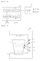
- FIG. 1 is a block diagram of a container sensing apparatus according to an exemplary embodiment in the present disclosure.
- the container sensing apparatus may include a signal sensing unit 10 and a control unit 20.
- the signal sensing unit 10 may transmit a detection signal sig_det at a predetermined angle of incidence and receive a reflection signal sig_ref corresponding to the detection signal sig_det reflected from a surface of a container c.
- the reflection signal sig_ref corresponding to the detection signal sig_det may be generated, but in a case in which the container c is not present, the reflection signal sig_ref may not be generated.
- the signal sensing unit 10 may not receive the reflection signal sig_ref.
- the signal sensing unit 10 may not receive the reflection signal sig_ref even after the detection signal sig_det is reflected from the surface of the container c.
- the control unit 20 may determine whether the container c is placed in the predetermined water receiving position by determining whether the signal sensing unit 10 has received the reflection signal sig_ref.
- the signal sensing unit 10 may determine whether the reflection signal sig_ref has been received by determining a magnitude of the reflection signal sig_ref.
- noise may be mixed with signals due to external conditions or the like when the signals are transmitted or received.
- the reflection signal sig_ref may be interrupted by indoor light, sunlight, or the like.
- the signal sensing unit 10 may determine that the reflection signal sig_ref has been received, and when a magnitude of the reflection signal sig_ref received by the signal sensing unit 10 is smaller than the predetermined reference magnitude, the signal sensing unit 10 may determine that the reflection signal sig_ref has not been received.
- the signal sensing unit 10 may include a transmitter t, a receiver r, and an operation controller 11, as illustrated in FIG. 1 .
- the transmitter t may transmit a detection signal sig_det at a predetermined angle of incidence
- the receiver r may receive a reflection signal sig_ref corresponding to the detection signal sig_det reflected from a surface of a container c.
- the transmitter t may be disposed to be tilted at a predetermined angle of incidence so as to transmit the detection signal sig_det at the angle of incidence.
- the receiver r may be disposed to be tilted at an angle of reflection corresponding to the angle of incidence so as to receive the reflection signal sig_ref.
- the angle of incidence and the angle of reflection may be determined by a distance between the container c and the transmitter t and between the transmitter t and the receiver r.
- the detection signal sig_det and the reflection signal sig_ref may be infrared light signals, and the infrared light signal may be a wave.
- the angle of incidence at which the detection signal sig_det is incident upon a surface of the container c may be equal to the angle of reflection at which the reflection signal sig_ref is reflected from the surface of the container c.
- the angle of incidence and the angle of reflection corresponding thereto may be determined.
- a plurality of transmitters t1 and t2 and receivers r1 and r2 may be installed in a height direction of the container c.
- Service lives of transmitters transmitting infrared light and receivers receiving infrared light are generally, relatively short.
- the service life of the signal sensing unit 10 may be increased by installing a plurality of transmitters and receivers, as illustrated in FIG. 2 , and alternately operating each of the plurality of transmitters and receivers.
- the plurality of transmitters and receivers may be provided as pairs such that each pair of the transmitters and receivers may be alternately operated, thereby allowing for an increase in the service life of the signal sensing unit 10.
- the pairs of transmitters and receivers may be determined according to paths of the detection signal sig_det and the reflection signal sig_ref. For example, since a detection signal of the first transmitter t1 is reflected from a container c and received by the first receiver r1, the first transmitter t1 and the first receiver r1 may be provided as a pair. Similarly, since a detection signal of the second transmitter t2 is reflected from the container c and received by the second receiver r2, the second transmitter t2 and the second receiver r2 may be provided as a pair.
- the pair of the second transmitter t2 and the second receiver r2 may be controlled to transmit the detection signal and receive the reflection signal, respectively, after the pair of the first transmitter t1 and the first receiver r1 transmit the detection signal and receive the reflection signal, respectively.
- detailed operating times of the transmitters t and the receivers r may be controlled by the operation controller 11.
- the operation controller 11 may control operating times of the transmitters t and the receivers r according to a predetermined operating mode.
- the operating mode may be divided into a standby mode and a sensing mode.
- the standby mode refers to an operating mode activated when the container c is not detected. The amount of power consumed during the standby mode may be reduced by significantly reducing operating times of the transmitters t and the receivers r.
- the sensing mode refers to an operating mode activated when the container c is detected. During the sensing mode, whether the container is placed in a predetermined water receiving position may be precisely determined.
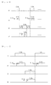
- FIG. 3 is a graph illustrating operations of the transmitters t and the receivers r.
- the first transmitter t1 may operate during every standby period (2.0s), a predetermined time period, and operate for a standby operation time (0.6s).
- the operation controller 11 may allow the first transmitter t1 to operate every 2.0s by controlling when power is supplied to the first transmitter t1, and may enable the first transmitter t1 to transmit a detection signal sig_det for 0.6s.
- the first receiver r1, paired with the first transmitter t1 may also operate during every standby period (2.0s), but may start operating 0.1s later than the first transmitter t1 does.
- the first receiver r1 may be operated later than the first transmitter t1, in consideration of a time required for the detection signal sig_det transmitted by the first transmitter t1 to be reflected from the container c and then received by the first receiver r1.
- the first receiver r1 may operate 0.1s later than the first transmitter t1 and standby to receive the reflection signal sig_ref for the standby operation time of 0.5s.
- the pair of the second transmitter t2 and the second receiver r2 may start a standby operation.
- the second transmitter t2 and the second receiver r2 may operate in the same manner as the first transmitter t1 and the first receiver r1.
- the second transmitter t2 and the second receiver r2 may have a standby period of 2.0s, and the second transmitter t2 may operate for a standby operation time of 0.6s.
- the second receiver r2 may start operating 0.1s later than the second transmitter t2 does and may operate for a standby operation time of 0.5s.
- the pair of the second transmitter t2 and the second receiver r2 may start operating after the pair of the first transmitter t1 and the first receiver r1 operate, operating in an alternating manner therewith.
- a time of 0.4s in which operations of the first transmitter t1, the first receiver r1, the second transmitter t2, and the second receiver r2 cease may be included between an operation of the pair of the first transmitter t1 and the first receiver r1 and an operation of the pair of the second transmitter t2 and the second receiver r2.
- the amount of power unnecessarily consumed during the standby mode may be saved by significantly reducing operations of the first transmitter t1, the first receiver r1, the second transmitter t2, and the second receiver r2.
- service lives of the first transmitter t1, the first receiver r1, the second transmitter t2, and the second receiver r2 may be increased.
- FIG. 4 is a graph illustrating operations of the transmitters t and the receivers r during a sensing mode.
- the first transmitter t1 may operate during every sensing period (2.0s), a predetermined time period, and the first transmitter t1 may transmit a detection signal sig_det for a sensing operation time of 1.0s.
- the first receiver r1, paired with the first transmitter t1 may also operate during every sensing period (2.0s), but may start operating 0.1s later than the first transmitter t1 does.
- the first receiver r1 may start operating later than the first transmitter t1, in consideration of a time required for the detection signal sig_det transmitted by the first transmitter t1 to be reflected from the container c and then received by the first receiver r1.
- the first receiver r1 may standby for the sensing operation time of 0.9s to receive the reflection signal sig_ref.
- a pair of the second transmitter t2 and the second receiver r2 may start sensing operations.
- the second transmitter t2 and the second receiver r2 may have a sensing period of 2.0s, and the second transmitter t2 may transmit a detection signal sig_det for a sensing operation time of 1.0s.
- the second receiver r2 may start operating 0.1s later than the second transmitter t2 does and may standby for a sensing operation time of 0.9s to receive the reflection signal.
- the pair of the second transmitter t2 and the second receiver r2 may start operating after the pair of the first transmitter t1 and the first receiver r1 operate, operating in an alternating manner therewith.
- operating times of the first transmitter t1, the first receiver r1, the second transmitter t2, and the second receiver r2 may be longer during the sensing mode than during the standby mode.
- the detection signal may be continuously transmitted by the first transmitter t1 and the second transmitter t2.
- the operating times of the first transmitter t1, the first receiver r1, the second transmitter t2, and the second receiver r2 are maintained for relatively long periods of time, such that whether the container c is placed in the predetermined water receiving position may be precisely detected.
- the reflection signal sig_ref may be reflected in a plurality of directions because the container c has not yet been placed in a precise water receiving position.
- a reflection signal sig_ref momentarily received by a receiver does not necessarily indicate that the container c is precisely placed in the water receiving position.
- the reflection signal sig_ref may indicate that the container c is present in the water receiving position.
- transmissions of the detection signals sig_det by the transmitters and standbys for the reflection signal sig_ref by the receivers may be continuously performed in a sensing mode, such that whether the container c is stably placed in the precise water receiving position may be determined.
- the operation controller 11 may switch an operating mode to the sensing mode.
- the reflection signal sig_ref received by the receiver r may indicate that the container c is provided in the water receiving position.
- the operating mode is switched to the sensing mode, whether the container c is placed in the water receiving position may be precisely detected.
- the reflection signal sig_ref is not received by the receiver r for a predetermined switching period of time after the operating mode is switched to the sensing mode, the operating mode may be switched to the standby mode back.
- the control unit 20 may determine whether the container c is placed in the predetermined water receiving position, using a reflection signal sig_ref received by the signal sensing unit 10. As described above, when the container c is present in the predetermined water receiving position, the signal sensing unit 10 may receive the reflection signal sig_ref corresponding to the detection signal sig_det reflected from a surface of the container c. On the other hand, in a case in which the container c is not present, or the container c is not placed in the precise water receiving position, the reflection signal may not be received by the signal sensing unit 10. Thus, the control unit 20 may determine whether or not the container is present in the precise water receiving position, by determining whether the reflection signal has been received by the signal sensing unit 10.
- control unit 20 may determine that the container c has been placed in the water receiving position only when a reflection signal sig_ref having a predetermined signal level or larger is continuously received for a predetermined time or longer. In this case, the control unit 20 may transmit a container sensing signal out_sens, and once the container sensing signal out_sens is transmitted, a water cock f may start to supply the container with fluid by discharging water.
- FIG. 5 is a view schematically illustrating a container sensing apparatus according to another exemplary embodiment in the present disclosure.
- the container sensing apparatus may include a sensing area disposed to be dented inwardly in which a plurality of transmitters t1 and t2 and receivers r1 and r2 are installed.
- the sensing area may be formed to be perpendicular to the height direction of the container c and dented inwardly by a predetermined length d or greater.
- the detection signal sig_det may be an infrared light signal.
- the reflection signal sig_ref may be received relatively poorly in a case in which a container c is placed relatively too close to the transmitters t1 and t2 and the receivers r1 and r2.
- the reflection signal sig_ref may not be precisely received in a case in which the container c is placed relatively too close to the transmitters t1 and t2 and the receivers r1 and r2.
- the transmitters t1 and t2 and the receiver r1 and r2 may be installed in the sensing area.
- the predetermined length d may be 10mm or greater.
- the container sensing apparatus may further include a sensor s below the water receiving position.
- the sensor s may be provided as a remote sensor to detect contact with the container c.
- the sensor s may detect contact with the container c, using a difference between a value measured by the remote sensor when the container is present and a value measured by the remote sensor when the container is not present. Whether the container is placed in the water receiving position may be determined more precisely and faster by using the sensor s as well as the transmitters t1 and t2 and the receivers r1 and r2.
- the sensor s since the sensor s is disposed below the water receiving position, the sensor may be affected by fluid discharged from the water cock. For example, in a case in which fluid discharged from the water cock drops to the water receiving position, a value measured by the sensor s may be changed due to the dropped fluid, and the sensor s may be rendered non-operational by moisture of the fluid or the like. Thus, in order to prevent such a breakdown from happening, a trench unit A may be further provided around the sensor s, as illustrated in FIG. 6 . In detail, the fluid dropping to an upper portion of the sensor s may flow into a grill unit g disposed in either sides of the trench unit A and be collected within the grill unit g. Thus, the influence of the fluid supplied to the upper portion of the sensor s on the sensor s may be significantly reduced.
- FIG. 7 is a schematic view illustrating a container sensing apparatus according to another exemplary embodiment in the present disclosure.
- the container sensing apparatus may include a plurality of transmitters t1 and t2 and a single receiver r.
- the plurality of transmitters t1 and t2 may be installed side by side, and an angle of incidence of the detection signal may be set so that respective detection signals sig_det transmitted by the transmitters t1 and t2 may be reflected from the container c and reflections thereof may be received by the receiver r.
- the transmitters t1 and t2 and the receiver r of the container sensing apparatus may operate according to the standby mode and the sensing mode illustrated in FIG. 3 and FIG. 4 .
- reflection signals sig_ref corresponding to the detection signals sig_det respectively transmitted by the transmitters t1 and t2 may be received by the single receiver r.
- the plurality of transmitters t1 and t2 may alternately transmit detection signals sig_det at regular intervals so that respective operating times of the transmitters may not be overlapped, and the receiver r may be synchronized by the operations of the transmitters t1 and t2 and receive the reflection signals sig_ref corresponding to the detection signals sig_det.
- the plurality of transmitters t1 and t2 may sequentially transmit the detection signals sig_det for a preset period of time before the operating mode is changed to the sensing mode. Then, when all the reflection signals sig_ref corresponding to the respective detection signals sig_det transmitted by the plurality of the transmitters t1 and t2 are received by the receiver r, the operating mode may be changed to the sensing mode.
- the presence of the container c may be determined by determining whether the reflection signals sig_ref from the plurality of transmitters t1 and t2 have been received by the receiver r. When it is determined that the container c is present, the operating mode may be changed to the sensing mode, such that the transmitters t1 and t2 and the receiver r may be operated as illustrated in FIG. 4 .
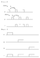
- the container sensing apparatus may detect the container in the manner illustrated in the FIG. 8 .
- the receiver r may receive a reflection signal sig_ref.
- the operating mode may not be switched right away, but may be switched from the standby mode to the sensing mode after it is determined whether the reflection signals sig_ref are continuously received by the receiver r during a predetermined container sensing time Pc.
- the container sensing time Pc may be set to be 1.5 seconds or so.
- the control unit 20 may output the container sensing signal out_sens and switch operating modes of the transmitters t1 and t2 and the receiver r to the sensing mode.
- the transmitters t1 and t2 and the receiver r may operate consecutively, and thus whether the container c is present may be continuously determined.
- the transmitter t1 transmitting the detection signal sig_det at a point in time P1 may continuously transmit the detection signal sig_det until the input of the reflection signal sig_ref to the receiver r ceases, and the receiver r may continuously receive the reflection signal sig_ref until the input of the reflection signal sig_ref thereto ceases.
- the water cock f may discharge fluid and supply a container c with the fluid, and then, since a case in which the input of the reflection signal sig_ref to the receiver r ceases indicates that the container c has been removed from the water receiving position, the fluid supply may be immediately stopped.
- the amount of fluid discharged to the outside of the container c may be significantly reduced.
- the method of detecting a container described above may be applied to the container sensing apparatus according to the exemplary embodiment in the present disclosure of FIG. 2 .
- the signal sensing apparatus may include a signal sensing unit 10 and a control unit 20.
- the control unit 20 may transmit a malfunction signal sig_mal.
- the control unit 20 may transmit the malfunction signal when a magnitude of the reflection signal sig_ref is maintained to be a predetermined magnitude or greater for a time less than a predetermined sensing time, or a magnitude of the reflection signal sig_ref is maintained to be less than the predetermined magnitude for a time less than the predetermined sensing time.
- the transmitter t1 and transmitter t2 may alternately transmit detection signals sig_det at an interval of 250ms, and a reflection signal sig_ref corresponding to the detection signal sig_det may be received by the receiver r.
- a reflection signal sig_ref corresponding to the detection signal sig_det may be received by the receiver r.
- the receiver r may receive the reflection signal sig_ref corresponding to the detection signal sig_det from the transmitter t1 having a reference magnitude or greater and the reflection signal sig_ref corresponding to the detection signal sig_det from the transmitter t2 having a magnitude smaller than the reference magnitude may occur.
- the container c may not be actually placed in the water receiving position, removed from the water receiving position in a time of 750ms or less, and then replaced in the water receiving position again in a time of 750ms.
- the control unit 20 may determine that the signal sensing unit 10 has a problem, and thus, the control unit 20 may transmit the malfunction signal out_mal.
- 750ms may be the sensing time.
- operating modes of transmitters t1, t2, and t3 and the receiver r may be in a breakdown sensing mode in order to detect breakdown of the container sensing apparatus.
- the operation controller 11 may perform a control such that the plurality of transmitters t1, t2, and t3 may transmit detection signals sig_det consecutively, and the receiver r1 may receive reflection signals sig_ref corresponding to the detection signals sig_det respectively transmitted by the plurality of transmitters t1, t2, and t3.
- the control unit 20 may output a malfunction signal out_mal indicating a breakdown of the signal sensing unit 10.
- the reflection signals sig_ref corresponding to the detection signals respectively transmitted by the transmitters t1, t2, and t3 should be measured to have a reference magnitude or greater.
- the reflection signal sig_ref from the transmitter t1 may have a reference magnitude or larger, but the reflection signal sig_ref from the transmitter t2 may have a magnitude smaller than a reference magnitude.
- a broken transmitter may be recognized.
- a reflection signal sig_ref having a reference magnitude or greater is received during a breakdown sensing mode while a container c is not present in the water receiving position, it may be determined that the transmitter has been broken.
- the water treatment apparatus may refer to a water purifier, a functional water purifier, a water heater, a water cooler, an ice maker, or apparatuses having at least a portion of respective functions thereof.
Landscapes
- Physics & Mathematics (AREA)
- Engineering & Computer Science (AREA)
- Electromagnetism (AREA)
- General Physics & Mathematics (AREA)
- Computer Networks & Wireless Communication (AREA)
- Radar, Positioning & Navigation (AREA)
- Remote Sensing (AREA)
- Life Sciences & Earth Sciences (AREA)
- General Life Sciences & Earth Sciences (AREA)
- Geophysics (AREA)
- Geophysics And Detection Of Objects (AREA)
- Measurement Of Levels Of Liquids Or Fluent Solid Materials (AREA)
Abstract
Description
- The present disclosure relates to a container sensing apparatus and a water treatment apparatus having the same, and more particularly, to a container sensing apparatus able to detect a provided container and a water treatment apparatus having the same.
- Water purifiers have been located in an increasing number of places, including homes, to allow efficient access to purified potable water. A water purifier is an apparatus which filters natural water such as tap water or underground water (hereinafter water before purification will be referred to as "raw water"), and water purifiers provide users with potable water by filtering raw water through filters and removing foreign substances or toxic substances from the water.
- When it comes to ordinary water purifiers, a user has to push or touch a mechanical or electronic button to get purified water. In this case, however, water may be spattered, and the user has to keep pushing or touching the button until a desired amount of water is dispensed, which is inconvenience for users. For the reason, water purifiers having an automatic water dispensing feature able to automatically fill a user's container with a fixed amount of water are widely used. However, in this case too, an additional motion such as pushing a button or the like should be performed by the user to get water. Therefore, a technology able to minimize user movement when the user gets water from a water purifier is required.
- A container sensing apparatus able to detect a provided container and a water treatment apparatus having the same may be provided.
- According to an aspect of the present disclosure, a container sensing apparatus may include a signal sensing unit transmitting a detection signal at a predetermined angle of incidence and receiving a reflection signal corresponding to the detection signal reflected from a surface of a container and a control unit determining whether the container is present in a predetermined water receiving position using the reflection signal.
- The signal sensing unit may include a plurality of transmitters transmitting the detection signal at the predetermined angle of incidence, at least one receiver receiving the reflection signal at an angle of reflection corresponding to the angle of incidence, and an operation controller controlling operating times of the plurality of transmitters and the at least one receiver according to a predetermined operating mode.
- The signal sensing unit may include a plurality of transmitters and receivers paired with each other and disposed along paths of the detection signal and the reflection signal.
- The signal sensing unit may include the plurality of transmitters corresponding to a single receiver, and when the plurality of transmitters sequentially transmit the detection signals, the single receiver may receive the reflection signals corresponding to the detection signals.
- The operation controller may operate the plurality of transmitters and the at least one receiver for a standby operation time during every standby period when the operating mode is in a standby mode, and operate the plurality of transmitters and the at least one receiver for a sensing operation time during every sensing period when the operating mode is in a sensing mode.
- A length of the standby period may be equal to or longer than a length of the sensing period, and a length of the standby operation time may be equal to or shorter than a length of the sensing operation time.
- The operation controller may switch the operating mode to the sensing mode when the at least one receiver receives the reflection signal during the standby mode, and switch the operating mode to the standby mode when the reflection signal is not received by the at least one receiver for a predetermined switching time during the sensing mode.
- When the at least one receiver receives the reflection signal during the standby mode, the operation controller may switch the operating mode to the sensing mode and operate the plurality of transmitters and the at least one receiver consecutively, and when an input of the reflection signal to the at least one receiver ceases, the operation controller may switch the operating mode to the standby mode.
- When the at least one receiver receives the reflection signal during the standby mode, the operation controller may operate to allow the plurality of transmitters to sequentially transmit the detection signals, and when all of the reflection signals corresponding to the detection signals respectively transmitted by the plurality of transmitters are received by the at least one receiver, the operation controller may change the operating mode to the sensing mode.
- The operation controller may operate a first transmitter and a first receiver provided as a pair among the plurality of transmitters and receivers for a first operating time, and operate a second transmitter and a second receiver provided as a pair among the plurality of transmitters and receivers for a second operating time, such that the pairs of the transmitters and the receivers may be alternately operated.
- The signal sensing unit may include the plurality of transmitters and receivers in a sensing area dented inwardly in a direction perpendicular to a height direction of the container.
- The container sensing apparatus may further include a sensor disposed below the water receiving position and detecting contact with the container.
- The container sensing apparatus may further include a trench unit formed around the sensor to allow fluid in an upper portion of the sensor to flow into a grill unit.
- The control unit may output a container sensing signal when a magnitude of the reflection signal is equal to or greater than a predetermined reference magnitude.
- The control unit may output a malfunction signal when the magnitude of the reflection signal is maintained to be equal to or greater than the predetermined reference magnitude for a time less than a predetermined sensing time or when a magnitude of the reflection signal is maintained to be smaller than the predetermined reference magnitude for a time less than the predetermined sensing time.
- When the operating mode is in a breakdown sensing mode, the operation controller may control the plurality of transmitters to sequentially transmit detection signals and operate the at least one receiver to receive reflection signals corresponding to the detection signals respectively transmitted by the plurality of transmitters.
- When a magnitude of the reflection signal received by the at least one receiver is changed to being smaller than the reference magnitude from being equal to or greater than the reference magnitude, or when the magnitude of the reflection signal received by the at least one receiver is changed to being equal to or larger than the reference magnitude from being smaller than the reference magnitude, the control unit may transmit a malfunction signal indicating a malfunction of the signal sensing unit.
- According to an aspect of the present disclosure, a water treatment apparatus may include the container sensing apparatus described above.
- According to an exemplary embodiment in the present disclosure, the container sensing apparatus and the water treatment apparatus having the same may detect whether or not a container is present.
- According to an exemplary embodiment in the present disclosure, the container sensing apparatus and the water treatment apparatus having the same may perform a different operation depending on a standby mode and a sensing mode, such that the amount of power consumed to detect a presence of a container may be significantly reduced.
- In the container sensing apparatus and the water treatment apparatus having the same according to exemplary embodiments in the present disclosure, transmitters and receivers paired with each other may operate alternately, such that service lives of the transmitters and the receivers may be increased.
- According to an exemplary embodiment in the present disclosure, the container sensing apparatus and the water treatment apparatus having the same may include a transmitter and a receiver disposed in a concave-shaped sensing area, such that the container may be prevented from being placed relatively too close to the transmitter and the receiver, and thus, a container may be detected more precisely.
- According to an exemplary embodiment in the present disclosure, the container sensing apparatus and the water treatment apparatus having the same may further include a sensor as well as a transmitter and a receiver, such that the container may be detected relatively quickly and more precisely.
-
-
FIG. 1 is a block diagram of a container sensing apparatus according to an exemplary embodiment in the present disclosure; -
FIG. 2 is a view schematically illustrating the container sensing apparatus according to an exemplary embodiment in the present disclosure; -
FIG. 3 is a graph illustrating an operation of the container sensing apparatus according to the exemplary embodiment in the present disclosure during a standby mode; -
FIG. 4 is a graph illustrating an operation of the container sensing apparatus according to the exemplary embodiment in the present disclosure during a sensing mode; -
FIG. 5 is a view schematically illustrating a container sensing apparatus according to another exemplary embodiment in the present disclosure; -
FIG. 6 is a schematic view illustrating a sensor and a trench unit included in the container sensing apparatus according to the exemplary embodiment in the present disclosure; -
FIGS. 7A and 7B are views schematically illustrating a container sensing apparatus according to an exemplary embodiment in the present disclosure; -
FIG. 8 is a graph illustrating detection of a container by the container sensing apparatus according to the exemplary embodiment in the present disclosure; and -
FIGS. 9 and10 are graphs illustrating a detection of malfunction of the container sensing apparatus according to the exemplary embodiment in the present disclosure. - Hereinafter, embodiments of the present disclosure will be described in detail with reference to the accompanying drawings.
- The disclosure may, however, be exemplified in many different forms and should not be construed as being limited to the specific embodiments set forth herein. Rather, these embodiments are provided so that this disclosure will be thorough and complete, and will fully convey the scope of the disclosure to those skilled in the art.
- In the drawings, the shapes and dimensions of elements may be exaggerated for clarity, and the same reference numerals will be used throughout to designate the same or like elements.
-
FIG. 1 is a block diagram of a container sensing apparatus according to an exemplary embodiment in the present disclosure. - Referring to
FIG. 1 , the container sensing apparatus according to an exemplary embodiment in the present disclosure may include asignal sensing unit 10 and acontrol unit 20. - Hereinafter, the container sensing apparatus according to an exemplary embodiment in the present disclosure will be described.
- The
signal sensing unit 10 may transmit a detection signal sig_det at a predetermined angle of incidence and receive a reflection signal sig_ref corresponding to the detection signal sig_det reflected from a surface of a container c. In a case in which the container c is present, the reflection signal sig_ref corresponding to the detection signal sig_det may be generated, but in a case in which the container c is not present, the reflection signal sig_ref may not be generated. In detail, in the case that the container c is not present, thesignal sensing unit 10 may not receive the reflection signal sig_ref. Further, in a case in which the container is not placed in a predetermined water receiving position, thesignal sensing unit 10 may not receive the reflection signal sig_ref even after the detection signal sig_det is reflected from the surface of the container c. Thus, thecontrol unit 20 may determine whether the container c is placed in the predetermined water receiving position by determining whether thesignal sensing unit 10 has received the reflection signal sig_ref. - The
signal sensing unit 10 may determine whether the reflection signal sig_ref has been received by determining a magnitude of the reflection signal sig_ref. In general, noise may be mixed with signals due to external conditions or the like when the signals are transmitted or received. For example, in a case in which an infrared light signal or the like is used as the detection signal sig_det, the reflection signal sig_ref may be interrupted by indoor light, sunlight, or the like. Thus, when a magnitude of the reflection signal sig_ref received by thesignal sensing unit 10 is equal to or greater than a predetermined reference magnitude, thesignal sensing unit 10 may determine that the reflection signal sig_ref has been received, and when a magnitude of the reflection signal sig_ref received by thesignal sensing unit 10 is smaller than the predetermined reference magnitude, thesignal sensing unit 10 may determine that the reflection signal sig_ref has not been received. - The
signal sensing unit 10 may include a transmitter t, a receiver r, and anoperation controller 11, as illustrated inFIG. 1 . - The transmitter t may transmit a detection signal sig_det at a predetermined angle of incidence, and the receiver r may receive a reflection signal sig_ref corresponding to the detection signal sig_det reflected from a surface of a container c. Here, the transmitter t may be disposed to be tilted at a predetermined angle of incidence so as to transmit the detection signal sig_det at the angle of incidence. In addition, the receiver r may be disposed to be tilted at an angle of reflection corresponding to the angle of incidence so as to receive the reflection signal sig_ref.
- The angle of incidence and the angle of reflection may be determined by a distance between the container c and the transmitter t and between the transmitter t and the receiver r. In detail, the detection signal sig_det and the reflection signal sig_ref may be infrared light signals, and the infrared light signal may be a wave. For example, since the Snell's law is applied, the angle of incidence at which the detection signal sig_det is incident upon a surface of the container c may be equal to the angle of reflection at which the reflection signal sig_ref is reflected from the surface of the container c. Thus, once the distance between the container c and the transmitter t and the distance between the transmitter t and the receiver r are determined, the angle of incidence and the angle of reflection corresponding thereto may be determined.
- In addition, as illustrated in
FIG. 2 , a plurality of transmitters t1 and t2 and receivers r1 and r2 may be installed in a height direction of the container c. Service lives of transmitters transmitting infrared light and receivers receiving infrared light are generally, relatively short. Thus, the service life of thesignal sensing unit 10 may be increased by installing a plurality of transmitters and receivers, as illustrated inFIG. 2 , and alternately operating each of the plurality of transmitters and receivers. In detail, the plurality of transmitters and receivers may be provided as pairs such that each pair of the transmitters and receivers may be alternately operated, thereby allowing for an increase in the service life of thesignal sensing unit 10. - The pairs of transmitters and receivers may be determined according to paths of the detection signal sig_det and the reflection signal sig_ref. For example, since a detection signal of the first transmitter t1 is reflected from a container c and received by the first receiver r1, the first transmitter t1 and the first receiver r1 may be provided as a pair. Similarly, since a detection signal of the second transmitter t2 is reflected from the container c and received by the second receiver r2, the second transmitter t2 and the second receiver r2 may be provided as a pair.
- In detail, the pair of the second transmitter t2 and the second receiver r2 may be controlled to transmit the detection signal and receive the reflection signal, respectively, after the pair of the first transmitter t1 and the first receiver r1 transmit the detection signal and receive the reflection signal, respectively. Here, detailed operating times of the transmitters t and the receivers r may be controlled by the
operation controller 11. - The
operation controller 11 may control operating times of the transmitters t and the receivers r according to a predetermined operating mode. In detail, the operating mode may be divided into a standby mode and a sensing mode. The standby mode refers to an operating mode activated when the container c is not detected. The amount of power consumed during the standby mode may be reduced by significantly reducing operating times of the transmitters t and the receivers r. The sensing mode refers to an operating mode activated when the container c is detected. During the sensing mode, whether the container is placed in a predetermined water receiving position may be precisely determined. -
FIG. 3 is a graph illustrating operations of the transmitters t and the receivers r. Referring toFIG. 3 , the first transmitter t1 may operate during every standby period (2.0s), a predetermined time period, and operate for a standby operation time (0.6s). In detail, theoperation controller 11 may allow the first transmitter t1 to operate every 2.0s by controlling when power is supplied to the first transmitter t1, and may enable the first transmitter t1 to transmit a detection signal sig_det for 0.6s. The first receiver r1, paired with the first transmitter t1, may also operate during every standby period (2.0s), but may start operating 0.1s later than the first transmitter t1 does. In detail, the first receiver r1 may be operated later than the first transmitter t1, in consideration of a time required for the detection signal sig_det transmitted by the first transmitter t1 to be reflected from the container c and then received by the first receiver r1. Thus, the first receiver r1 may operate 0.1s later than the first transmitter t1 and standby to receive the reflection signal sig_ref for the standby operation time of 0.5s. - After the standby operation time of the first transmitter t1 and the first receiver r1, the pair of the second transmitter t2 and the second receiver r2 may start a standby operation. As illustrated in
FIG. 3 , the second transmitter t2 and the second receiver r2 may operate in the same manner as the first transmitter t1 and the first receiver r1. In detail, the second transmitter t2 and the second receiver r2 may have a standby period of 2.0s, and the second transmitter t2 may operate for a standby operation time of 0.6s. In addition, the second receiver r2 may start operating 0.1s later than the second transmitter t2 does and may operate for a standby operation time of 0.5s. Here, as illustrated inFIG. 3 , the pair of the second transmitter t2 and the second receiver r2 may start operating after the pair of the first transmitter t1 and the first receiver r1 operate, operating in an alternating manner therewith. - Further, referring to
FIG. 3 , a time of 0.4s in which operations of the first transmitter t1, the first receiver r1, the second transmitter t2, and the second receiver r2 cease may be included between an operation of the pair of the first transmitter t1 and the first receiver r1 and an operation of the pair of the second transmitter t2 and the second receiver r2. During the time of 0.4s, the amount of power unnecessarily consumed during the standby mode may be saved by significantly reducing operations of the first transmitter t1, the first receiver r1, the second transmitter t2, and the second receiver r2. In addition, in this case, service lives of the first transmitter t1, the first receiver r1, the second transmitter t2, and the second receiver r2 may be increased. -
FIG. 4 is a graph illustrating operations of the transmitters t and the receivers r during a sensing mode. Referring toFIG. 4 , the first transmitter t1 may operate during every sensing period (2.0s), a predetermined time period, and the first transmitter t1 may transmit a detection signal sig_det for a sensing operation time of 1.0s. The first receiver r1, paired with the first transmitter t1, may also operate during every sensing period (2.0s), but may start operating 0.1s later than the first transmitter t1 does. In detail, the first receiver r1 may start operating later than the first transmitter t1, in consideration of a time required for the detection signal sig_det transmitted by the first transmitter t1 to be reflected from the container c and then received by the first receiver r1. Thus, the first receiver r1 may standby for the sensing operation time of 0.9s to receive the reflection signal sig_ref. - In detail, after the sensing operation time of the pair of the first transmitter t1 and the first receiver r1, a pair of the second transmitter t2 and the second receiver r2 may start sensing operations. As illustrated in
FIG. 4 , the second transmitter t2 and the second receiver r2 may have a sensing period of 2.0s, and the second transmitter t2 may transmit a detection signal sig_det for a sensing operation time of 1.0s. The second receiver r2 may start operating 0.1s later than the second transmitter t2 does and may standby for a sensing operation time of 0.9s to receive the reflection signal. Similarly, as illustrated inFIG. 4 , the pair of the second transmitter t2 and the second receiver r2 may start operating after the pair of the first transmitter t1 and the first receiver r1 operate, operating in an alternating manner therewith. - Referring to
FIG. 4 , operating times of the first transmitter t1, the first receiver r1, the second transmitter t2, and the second receiver r2 may be longer during the sensing mode than during the standby mode. In addition, during the sensing mode, the detection signal may be continuously transmitted by the first transmitter t1 and the second transmitter t2. In detail, the operating times of the first transmitter t1, the first receiver r1, the second transmitter t2, and the second receiver r2 are maintained for relatively long periods of time, such that whether the container c is placed in the predetermined water receiving position may be precisely detected. For example, while a user is placing a container c in a water receiving position, the reflection signal sig_ref may be reflected in a plurality of directions because the container c has not yet been placed in a precise water receiving position. Thus, a reflection signal sig_ref momentarily received by a receiver does not necessarily indicate that the container c is precisely placed in the water receiving position. After a while, when the container c is stably placed in the water receiving position and the reflection signal sig_ref is continuously received, the reflection signal sig_ref may indicate that the container c is present in the water receiving position. Thus, transmissions of the detection signals sig_det by the transmitters and standbys for the reflection signal sig_ref by the receivers may be continuously performed in a sensing mode, such that whether the container c is stably placed in the precise water receiving position may be determined. - Here, when the receiver r receives the reflection signal sig_ref during the standby mode, the
operation controller 11 may switch an operating mode to the sensing mode. In detail, the reflection signal sig_ref received by the receiver r may indicate that the container c is provided in the water receiving position. Thus, as the operating mode is switched to the sensing mode, whether the container c is placed in the water receiving position may be precisely detected. In addition, when the reflection signal sig_ref is not received by the receiver r for a predetermined switching period of time after the operating mode is switched to the sensing mode, the operating mode may be switched to the standby mode back. - The
control unit 20 may determine whether the container c is placed in the predetermined water receiving position, using a reflection signal sig_ref received by thesignal sensing unit 10. As described above, when the container c is present in the predetermined water receiving position, thesignal sensing unit 10 may receive the reflection signal sig_ref corresponding to the detection signal sig_det reflected from a surface of the container c. On the other hand, in a case in which the container c is not present, or the container c is not placed in the precise water receiving position, the reflection signal may not be received by thesignal sensing unit 10. Thus, thecontrol unit 20 may determine whether or not the container is present in the precise water receiving position, by determining whether the reflection signal has been received by thesignal sensing unit 10. - In detail, the
control unit 20 may determine that the container c has been placed in the water receiving position only when a reflection signal sig_ref having a predetermined signal level or larger is continuously received for a predetermined time or longer. In this case, thecontrol unit 20 may transmit a container sensing signal out_sens, and once the container sensing signal out_sens is transmitted, a water cock f may start to supply the container with fluid by discharging water. -
FIG. 5 is a view schematically illustrating a container sensing apparatus according to another exemplary embodiment in the present disclosure. Referring toFIG. 5 , the container sensing apparatus according to another exemplary embodiment in the present disclosure may include a sensing area disposed to be dented inwardly in which a plurality of transmitters t1 and t2 and receivers r1 and r2 are installed. In detail, the sensing area may be formed to be perpendicular to the height direction of the container c and dented inwardly by a predetermined length d or greater. The detection signal sig_det may be an infrared light signal. In this case, the reflection signal sig_ref may be received relatively poorly in a case in which a container c is placed relatively too close to the transmitters t1 and t2 and the receivers r1 and r2. In other words, the reflection signal sig_ref may not be precisely received in a case in which the container c is placed relatively too close to the transmitters t1 and t2 and the receivers r1 and r2. Accordingly, in order to prevent the reflection signal sig_ref being received relatively poorly, the transmitters t1 and t2 and the receiver r1 and r2 may be installed in the sensing area. Here, the predetermined length d may be 10mm or greater. - Referring to
FIG. 5 , the container sensing apparatus may further include a sensor s below the water receiving position. The sensor s may be provided as a remote sensor to detect contact with the container c. In detail, the sensor s may detect contact with the container c, using a difference between a value measured by the remote sensor when the container is present and a value measured by the remote sensor when the container is not present. Whether the container is placed in the water receiving position may be determined more precisely and faster by using the sensor s as well as the transmitters t1 and t2 and the receivers r1 and r2. In further detail, in a case in which only the transmitters t1 and t2 and the receivers r1 and r2 are installed, it may be difficult for the water cock f to supply the container c with fluid at an appropriate time, so the sensor s may be complementarily used. - However, since the sensor s is disposed below the water receiving position, the sensor may be affected by fluid discharged from the water cock. For example, in a case in which fluid discharged from the water cock drops to the water receiving position, a value measured by the sensor s may be changed due to the dropped fluid, and the sensor s may be rendered non-operational by moisture of the fluid or the like. Thus, in order to prevent such a breakdown from happening, a trench unit A may be further provided around the sensor s, as illustrated in
FIG. 6 . In detail, the fluid dropping to an upper portion of the sensor s may flow into a grill unit g disposed in either sides of the trench unit A and be collected within the grill unit g. Thus, the influence of the fluid supplied to the upper portion of the sensor s on the sensor s may be significantly reduced. -
FIG. 7 is a schematic view illustrating a container sensing apparatus according to another exemplary embodiment in the present disclosure. Referring toFIG. 7 , the container sensing apparatus may include a plurality of transmitters t1 and t2 and a single receiver r. In detail, as illustrated inFIG. 7B , the plurality of transmitters t1 and t2 may be installed side by side, and an angle of incidence of the detection signal may be set so that respective detection signals sig_det transmitted by the transmitters t1 and t2 may be reflected from the container c and reflections thereof may be received by the receiver r. The transmitters t1 and t2 and the receiver r of the container sensing apparatus may operate according to the standby mode and the sensing mode illustrated inFIG. 3 and FIG. 4 . Here, reflection signals sig_ref corresponding to the detection signals sig_det respectively transmitted by the transmitters t1 and t2 may be received by the single receiver r. - The plurality of transmitters t1 and t2 may alternately transmit detection signals sig_det at regular intervals so that respective operating times of the transmitters may not be overlapped, and the receiver r may be synchronized by the operations of the transmitters t1 and t2 and receive the reflection signals sig_ref corresponding to the detection signals sig_det.
- In addition, when the receiver r receives the reflection signal sig_ref during the standby mode, the plurality of transmitters t1 and t2 may sequentially transmit the detection signals sig_det for a preset period of time before the operating mode is changed to the sensing mode. Then, when all the reflection signals sig_ref corresponding to the respective detection signals sig_det transmitted by the plurality of the transmitters t1 and t2 are received by the receiver r, the operating mode may be changed to the sensing mode. In detail, the presence of the container c may be determined by determining whether the reflection signals sig_ref from the plurality of transmitters t1 and t2 have been received by the receiver r. When it is determined that the container c is present, the operating mode may be changed to the sensing mode, such that the transmitters t1 and t2 and the receiver r may be operated as illustrated in
FIG. 4 . - Additionally, the container sensing apparatus may detect the container in the manner illustrated in the
FIG. 8 . In detail, while the transmitters t1 and t2 and the receiver r are in the standby mode, the receiver r may receive a reflection signal sig_ref. Here, the operating mode may not be switched right away, but may be switched from the standby mode to the sensing mode after it is determined whether the reflection signals sig_ref are continuously received by the receiver r during a predetermined container sensing time Pc. In this case, since a misoperation of the container sensing apparatus incurred by an input error of the reflection signal sig_ref or the like may be prevented from happening, reliability in detecting a container may be improved. The container sensing time Pc may be set to be 1.5 seconds or so. - When the reflection signals sig_ref are continuously received by the receiver r during the container sensing time Pc, it may be determined that the container is present in the water receiving position. Thus, the
control unit 20 may output the container sensing signal out_sens and switch operating modes of the transmitters t1 and t2 and the receiver r to the sensing mode. Here, during the sensing mode, the transmitters t1 and t2 and the receiver r may operate consecutively, and thus whether the container c is present may be continuously determined. In detail, the transmitter t1 transmitting the detection signal sig_det at a point in time P1 may continuously transmit the detection signal sig_det until the input of the reflection signal sig_ref to the receiver r ceases, and the receiver r may continuously receive the reflection signal sig_ref until the input of the reflection signal sig_ref thereto ceases. From the time P1, the water cock f may discharge fluid and supply a container c with the fluid, and then, since a case in which the input of the reflection signal sig_ref to the receiver r ceases indicates that the container c has been removed from the water receiving position, the fluid supply may be immediately stopped. Thus, even in a case in which the container is removed from the water receiving position while the fluid is being discharged, the amount of fluid discharged to the outside of the container c may be significantly reduced. The method of detecting a container described above may be applied to the container sensing apparatus according to the exemplary embodiment in the present disclosure ofFIG. 2 . - In addition, whether the container sensing apparatus is non-operational may be detected. Hereinafter, a method of detecting a breakdown of the container sensing apparatus will be described, referring to
FIG. 9 andFIG. 10 . - As illustrated in
FIG. 1 , the signal sensing apparatus may include asignal sensing unit 10 and acontrol unit 20. When a malfunction of thesignal sensing unit 10 is detected, thecontrol unit 20 may transmit a malfunction signal sig_mal. In detail, thecontrol unit 20 may transmit the malfunction signal when a magnitude of the reflection signal sig_ref is maintained to be a predetermined magnitude or greater for a time less than a predetermined sensing time, or a magnitude of the reflection signal sig_ref is maintained to be less than the predetermined magnitude for a time less than the predetermined sensing time. - In detail, as illustrated in
FIG. 9 , the transmitter t1 and transmitter t2 may alternately transmit detection signals sig_det at an interval of 250ms, and a reflection signal sig_ref corresponding to the detection signal sig_det may be received by the receiver r. A case in which the receiver r may receive the reflection signal sig_ref corresponding to the detection signal sig_det from the transmitter t1 having a reference magnitude or greater and the reflection signal sig_ref corresponding to the detection signal sig_det from the transmitter t2 having a magnitude smaller than the reference magnitude may occur. In this case, since the interval of the detection signals of the transmitters t1 and t2 is about 750ms, the container c may not be actually placed in the water receiving position, removed from the water receiving position in a time of 750ms or less, and then replaced in the water receiving position again in a time of 750ms. Thus, in a case in which a magnitude of the reflection signal sig_ref is maintained to be a reference magnitude or larger for a relatively short time, for example, for less than 750ms, thecontrol unit 20 may determine that thesignal sensing unit 10 has a problem, and thus, thecontrol unit 20 may transmit the malfunction signal out_mal. Here, 750ms may be the sensing time. - As illustrated in
FIG. 10 , operating modes of transmitters t1, t2, and t3 and the receiver r may be in a breakdown sensing mode in order to detect breakdown of the container sensing apparatus. During the breakdown sensing mode, theoperation controller 11 may perform a control such that the plurality of transmitters t1, t2, and t3 may transmit detection signals sig_det consecutively, and the receiver r1 may receive reflection signals sig_ref corresponding to the detection signals sig_det respectively transmitted by the plurality of transmitters t1, t2, and t3. Here, in a case in which a magnitude of the reflection signal sig_ref is changed to a magnitude smaller than the reference magnitude from the reference magnitude or larger, or in a case in which a magnitude of the reflection signal sig_ref is changed to the reference magnitude or greater from a magnitude smaller than the reference magnitude, thecontrol unit 20 may output a malfunction signal out_mal indicating a breakdown of thesignal sensing unit 10. For example, when an operating mode is switched to the breakdown sensing mode with a container being present in the water receiving position, the reflection signals sig_ref corresponding to the detection signals respectively transmitted by the transmitters t1, t2, and t3 should be measured to have a reference magnitude or greater. However, in a case in which the transmitter t2 is broken, the reflection signal sig_ref from the transmitter t1 may have a reference magnitude or larger, but the reflection signal sig_ref from the transmitter t2 may have a magnitude smaller than a reference magnitude. Thus, from among the transmitters t1, t2 and t3, a broken transmitter may be recognized. In a case in which a reflection signal sig_ref having a reference magnitude or greater is received during a breakdown sensing mode while a container c is not present in the water receiving position, it may be determined that the transmitter has been broken. - Although not illustrated, various kinds of water treatment apparatuses including the container sensing apparatus according to an exemplary embodiment in the present disclosure may be provided. Here, the water treatment apparatus may refer to a water purifier, a functional water purifier, a water heater, a water cooler, an ice maker, or apparatuses having at least a portion of respective functions thereof.
- While exemplary embodiments have been shown and described above, it will be apparent to those skilled in the art that modifications and variations could be made without departing from the scope of the present invention as defined by the appended claims.
Claims (18)
- A container sensing apparatus, comprising:a signal sensing unit transmitting a detection signal at a predetermined angle of incidence and receiving a reflection signal corresponding to the detection signal reflected from a surface of a container; anda control unit determining whether the container is present in a predetermined water receiving position using the reflection signal.
- The container sensing apparatus of claim 1, wherein the signal sensing unit includes a plurality of transmitters transmitting the detection signal at the predetermined angle of incidence;
at least one receiver receiving the reflection signal at an angle of reflection corresponding to the angle of incidence; and
an operation controller controlling operating times of the plurality of transmitters and the at least one receiver according to a predetermined operating mode. - The container sensing apparatus of claim 2, wherein the signal sensing unit includes a plurality of transmitters and receivers paired with each other and disposed along paths of the detection signal and the reflection signal.
- The container sensing apparatus of claim 2, wherein the signal sensing unit includes the plurality of transmitters corresponding to a single receiver, and when the plurality of transmitters sequentially transmit the detection signals, the single receiver receives the reflection signals corresponding to the detection signals.
- The container sensing apparatus of claim 2, wherein the operation controller operates the plurality of transmitters and the at least one receiver for a standby operation time during every standby period when the operating mode is in a standby mode, and operates the plurality of transmitters and the at least one receiver for a sensing operation time during every sensing period when the operating mode is in a sensing mode.
- The container sensing apparatus of claim 5, wherein a length of the standby period is equal to or longer than a length of the sensing period, and a length of the standby operation time is equal to or shorter than a length of the sensing operation time.
- The container sensing apparatus of claim 5, wherein the operation controller switches the operating mode to the sensing mode when the at least one receiver receives the reflection signal during the standby mode, and switches the operating mode to the standby mode when the reflection signal is not received by the at least one receiver for a predetermined switching time during the sensing mode.
- The container sensing apparatus of claim 5, wherein when the at least one receiver receives the reflection signal during the standby mode, the operation controller switches the operating mode to the sensing mode and operates the plurality of transmitters and the at least one receiver consecutively, and when an input of the reflection signal to the at least one receiver ceases, the operation controller switches the operating mode to the standby mode.
- The container sensing apparatus of claim 5, wherein when the at least one receiver receives the reflection signal during the standby mode, the operation controller operates to allow the plurality of transmitters to sequentially transmit the detection signals, and when all of the reflection signals corresponding to the detection signals respectively transmitted by the plurality of transmitters are received by the at least one receiver, the operation controller changes the operating mode to the sensing mode.
- The container sensing apparatus of claim 3, wherein the operation controller operates a first transmitter and a first receiver provided as a pair among the plurality of transmitters and receivers for a first operating time, and operates a second transmitter and a second receiver provided as a pair among the plurality of transmitters and receivers for a second operating time, such that the pairs of the transmitters and the receivers are alternately operated.
- The container sensing apparatus of claim 3, wherein the signal sensing unit includes the plurality of transmitters and receivers in a sensing area dented inwardly in a direction perpendicular to a height direction of the container.
- The container sensing apparatus of claim 1, further comprising a sensor disposed below the water receiving position and detecting contact with the container.
- The container sensing apparatus of claim 12, further comprising a trench unit formed around the sensor to allow fluid in an upper portion of the sensor to flow into a grill unit.
- The container sensing apparatus of claim 13, wherein the control unit outputs a container sensing signal when a magnitude of the reflection signal is equal to or greater than a predetermined reference magnitude.
- The container sensing apparatus of claim 2, wherein the control unit outputs a malfunction signal when the magnitude of the reflection signal is maintained to be equal to or greater than the predetermined reference magnitude for a time less than a predetermined sensing time or when a magnitude of the reflection signal is maintained to be smaller than the predetermined reference magnitude for a time less than the predetermined sensing time.
- The container sensing apparatus of claim 2, wherein when the operating mode is in a breakdown sensing mode, the operation controller controls the plurality of transmitters to sequentially transmit detection signals and operates the at least one receiver to receive reflection signals corresponding to the detection signals respectively transmitted by the plurality of transmitters.
- The container sensing apparatus of claim 16, wherein when a magnitude of the reflection signal received by the at least one receiver is changed to being smaller than the reference magnitude from being equal to or greater than the reference magnitude, or when the magnitude of the reflection signal received by the at least one receiver is changed to being equal to or larger than the reference magnitude from being smaller than the reference magnitude, the control unit transmits a malfunction signal indicating a malfunction of the signal sensing unit.
- A water treatment apparatus comprising the container sensing apparatus of claim 1.
Applications Claiming Priority (3)
| Application Number | Priority Date | Filing Date | Title |
|---|---|---|---|
| KR20120156757 | 2012-12-28 | ||
| KR1020130063311A KR102046479B1 (en) | 2012-12-28 | 2013-06-03 | Apparatus for detecting container and water treatment apparatus having the same |
| PCT/KR2013/010920 WO2014104594A1 (en) | 2012-12-28 | 2013-11-28 | Container sensing device and water-treatment apparatus having same |
Publications (3)
| Publication Number | Publication Date |
|---|---|
| EP2940491A1 true EP2940491A1 (en) | 2015-11-04 |
| EP2940491A4 EP2940491A4 (en) | 2016-01-06 |
| EP2940491B1 EP2940491B1 (en) | 2023-03-22 |
Family
ID=51736803
Family Applications (1)
| Application Number | Title | Priority Date | Filing Date |
|---|---|---|---|
| EP13867076.5A Active EP2940491B1 (en) | 2012-12-28 | 2013-11-28 | Container sensing device and water-treatment apparatus having same |
Country Status (4)
| Country | Link |
|---|---|
| EP (1) | EP2940491B1 (en) |
| KR (1) | KR102046479B1 (en) |
| CN (1) | CN104884975B (en) |
| WO (1) | WO2014104594A1 (en) |
Cited By (2)
| Publication number | Priority date | Publication date | Assignee | Title |
|---|---|---|---|---|
| EP3015419A4 (en) * | 2013-06-26 | 2016-06-15 | Coway Co Ltd | AUTOMATIC EXTRACTION DEVICE AND METHOD FOR CONTROLLING AUTOMATIC EXTRACTION |
| CN115358360A (en) * | 2022-09-06 | 2022-11-18 | 深圳迪米生活科技有限公司 | Consumption control method, equipment and consumption control system of consumable |
Families Citing this family (2)
| Publication number | Priority date | Publication date | Assignee | Title |
|---|---|---|---|---|
| EP3354629A1 (en) * | 2017-01-31 | 2018-08-01 | Centre National De La Recherche Scientifique | Material having a metal layer and a process for preparing this material |
| NO345211B1 (en) * | 2018-09-10 | 2020-11-09 | Norsk Hydro As | Method to determining a presence or absence of water in a DC casting starter block and DC casting equipment |
Family Cites Families (15)
| Publication number | Priority date | Publication date | Assignee | Title |
|---|---|---|---|---|
| US4437499A (en) * | 1981-05-11 | 1984-03-20 | Everpure, Inc. | Computer controlled sensor for beverage dispenser |
| US5744793A (en) * | 1994-02-28 | 1998-04-28 | Electro-Pro, Inc. | Triangulation position-detection and integrated dispensing valve |
| US5862844A (en) * | 1996-05-03 | 1999-01-26 | Nartron Corporation | Methods and systems for controlling a dispensing apparatus |
| KR980008287A (en) * | 1996-07-22 | 1998-04-30 | 김광호 | Water intake system of cold and warm water purifier |
| US6265709B1 (en) * | 1997-02-04 | 2001-07-24 | Control Products, Inc. | Apparatus and method for detecting an object using digitally encoded optical data |
| US6394153B2 (en) * | 1998-04-01 | 2002-05-28 | Electro-Pro, Inc. | Control method and apparatus to detect the presence of a first object and monitor a relative position of the first or subsequent objects such as container identification and product fill control |
| JP3665890B2 (en) * | 2000-12-28 | 2005-06-29 | 理化工業株式会社 | Capacitance type detector |
| KR200338582Y1 (en) * | 2003-10-21 | 2004-01-16 | 정애숙 | clean water machine having a sterilizer for a water nozzle |
| KR100701928B1 (en) * | 2005-05-19 | 2007-03-30 | 위니아만도 주식회사 | Filter Flushing Method of Water Purifier |
| JP4725439B2 (en) * | 2006-07-07 | 2011-07-13 | 富士電機リテイルシステムズ株式会社 | Bill validator |
| FI123072B (en) * | 2009-05-26 | 2012-10-31 | Oras Oy | The fluid distribution apparatus |
| KR101651125B1 (en) * | 2009-06-29 | 2016-08-25 | 엘지전자 주식회사 | Mobile terminal and method for displaying image thereof |
| KR20110000880U (en) * | 2009-07-20 | 2011-01-27 | 웅진코웨이주식회사 | Water purifier |
| KR101093765B1 (en) * | 2009-12-09 | 2011-12-19 | 위니아만도 주식회사 | Control method of cold ion water purifier |
| CN102178461A (en) * | 2011-04-25 | 2011-09-14 | 宫绍康 | Automatic water overflow preventing device for water fountain |
-
2013
- 2013-06-03 KR KR1020130063311A patent/KR102046479B1/en active Active
- 2013-11-28 EP EP13867076.5A patent/EP2940491B1/en active Active
- 2013-11-28 WO PCT/KR2013/010920 patent/WO2014104594A1/en not_active Ceased
- 2013-11-28 CN CN201380068436.8A patent/CN104884975B/en active Active
Cited By (3)
| Publication number | Priority date | Publication date | Assignee | Title |
|---|---|---|---|---|
| EP3015419A4 (en) * | 2013-06-26 | 2016-06-15 | Coway Co Ltd | AUTOMATIC EXTRACTION DEVICE AND METHOD FOR CONTROLLING AUTOMATIC EXTRACTION |
| US9957147B2 (en) | 2013-06-26 | 2018-05-01 | Coway Co., Ltd | Automatic extraction device and method for controlling automatic extraction |
| CN115358360A (en) * | 2022-09-06 | 2022-11-18 | 深圳迪米生活科技有限公司 | Consumption control method, equipment and consumption control system of consumable |
Also Published As
| Publication number | Publication date |
|---|---|
| EP2940491A4 (en) | 2016-01-06 |
| EP2940491B1 (en) | 2023-03-22 |
| CN104884975B (en) | 2017-08-01 |
| KR20140087976A (en) | 2014-07-09 |
| CN104884975A (en) | 2015-09-02 |
| KR102046479B1 (en) | 2019-11-19 |
| WO2014104594A1 (en) | 2014-07-03 |
Similar Documents
| Publication | Publication Date | Title |
|---|---|---|
| EP2940491B1 (en) | Container sensing device and water-treatment apparatus having same | |
| US7121292B2 (en) | Gray water reclamation system and method for providing and operating same | |
| EP3015419B1 (en) | Automatic extraction device and method for controlling automatic extraction | |
| US10261523B2 (en) | Apparatus and method for controlling irrigation process by sending encoded acoustical messages along irrigation conduit | |
| US9057632B2 (en) | Apparatus and method for measuring flow rate of meter | |
| EP2972024B1 (en) | Single infrared emitter vessel detector | |
| KR101441240B1 (en) | Automatic apparatus and the method for supply water | |
| CN206612544U (en) | Cooking equipment | |
| GB2457141A (en) | Automatic faucet | |
| US20050195087A1 (en) | Air-in-line detector with warning device | |
| KR101450643B1 (en) | Automatic water supply control device | |
| WO2019221825A1 (en) | Infrared safety beam system | |
| KR20140050215A (en) | Apparatus for detecting ice cube and water purifier having the same | |
| KR101977026B1 (en) | Apparatus for automatic fluid extracting and method for the same | |
| KR101977023B1 (en) | Water purifier and operating method thereof | |
| JP5495170B2 (en) | Sanitary washing device system | |
| JP5672636B2 (en) | Automatic faucet | |
| EP3848679A1 (en) | Apparatus for measuring fluid flow | |
| JP2007327775A (en) | Alarm management system | |
| KR100350848B1 (en) | Wireless automatic control apparatus for maintaining predetermined water level | |
| KR101373684B1 (en) | Ultrasonic water level measurement apparatus that can be controlled different frequency band in multi-channel and water level control method using that | |
| JP2013060790A (en) | Automatic faucet | |
| CN101790705A (en) | Programmable system for inspecting mechanical components | |
| KR20240152135A (en) | Ultrasonic sensor module for water purifier with moisture removal function and water purifier using the same | |
| KR20150022449A (en) | Apparatus for detecting container and method for the same |
Legal Events
| Date | Code | Title | Description |
|---|---|---|---|
| PUAI | Public reference made under article 153(3) epc to a published international application that has entered the european phase |
Free format text: ORIGINAL CODE: 0009012 |
|
| 17P | Request for examination filed |
Effective date: 20150710 |
|
| AK | Designated contracting states |
Kind code of ref document: A1 Designated state(s): AL AT BE BG CH CY CZ DE DK EE ES FI FR GB GR HR HU IE IS IT LI LT LU LV MC MK MT NL NO PL PT RO RS SE SI SK SM TR |
|
| AX | Request for extension of the european patent |
Extension state: BA ME |
|
| A4 | Supplementary search report drawn up and despatched |
Effective date: 20151204 |
|
| RIC1 | Information provided on ipc code assigned before grant |
Ipc: G01S 17/00 20060101AFI20151130BHEP Ipc: G01V 8/10 20060101ALI20151130BHEP Ipc: B01D 35/00 20060101ALI20151130BHEP Ipc: G01V 8/20 20060101ALI20151130BHEP Ipc: G01S 17/87 20060101ALI20151130BHEP Ipc: G01S 17/02 20060101ALI20151130BHEP |
|
| DAX | Request for extension of the european patent (deleted) | ||
| STAA | Information on the status of an ep patent application or granted ep patent |
Free format text: STATUS: EXAMINATION IS IN PROGRESS |
|
| 17Q | First examination report despatched |
Effective date: 20180413 |
|
| REG | Reference to a national code |
Ref country code: DE Ref legal event code: R079 Ref document number: 602013083486 Country of ref document: DE Free format text: PREVIOUS MAIN CLASS: G01V0008100000 Ipc: G01S0017000000 |
|
| RIC1 | Information provided on ipc code assigned before grant |
Ipc: B01D 35/00 20060101ALI20201022BHEP Ipc: G01S 17/87 20200101ALI20201022BHEP Ipc: G01V 8/20 20060101ALI20201022BHEP Ipc: G01S 17/04 20200101ALI20201022BHEP Ipc: G01V 8/22 20060101ALI20201022BHEP Ipc: G01V 8/10 20060101ALI20201022BHEP Ipc: G01S 17/00 20200101AFI20201022BHEP Ipc: G01S 17/02 20200101ALI20201022BHEP |
|
| GRAP | Despatch of communication of intention to grant a patent |
Free format text: ORIGINAL CODE: EPIDOSNIGR1 |
|
| STAA | Information on the status of an ep patent application or granted ep patent |
Free format text: STATUS: GRANT OF PATENT IS INTENDED |
|
| INTG | Intention to grant announced |
Effective date: 20221006 |
|
| GRAS | Grant fee paid |
Free format text: ORIGINAL CODE: EPIDOSNIGR3 |
|
| GRAA | (expected) grant |
Free format text: ORIGINAL CODE: 0009210 |
|
| STAA | Information on the status of an ep patent application or granted ep patent |
Free format text: STATUS: THE PATENT HAS BEEN GRANTED |
|
| AK | Designated contracting states |
Kind code of ref document: B1 Designated state(s): AL AT BE BG CH CY CZ DE DK EE ES FI FR GB GR HR HU IE IS IT LI LT LU LV MC MK MT NL NO PL PT RO RS SE SI SK SM TR |
|
| REG | Reference to a national code |
Ref country code: GB Ref legal event code: FG4D |
|
| REG | Reference to a national code |
Ref country code: CH Ref legal event code: EP |
|
| REG | Reference to a national code |
Ref country code: DE Ref legal event code: R096 Ref document number: 602013083486 Country of ref document: DE |
|
| REG | Reference to a national code |
Ref country code: IE Ref legal event code: FG4D |
|
| REG | Reference to a national code |
Ref country code: AT Ref legal event code: REF Ref document number: 1555648 Country of ref document: AT Kind code of ref document: T Effective date: 20230415 |
|
| REG | Reference to a national code |
Ref country code: LT Ref legal event code: MG9D |
|
| REG | Reference to a national code |
Ref country code: NL Ref legal event code: MP Effective date: 20230322 |
|
| PG25 | Lapsed in a contracting state [announced via postgrant information from national office to epo] |
Ref country code: RS Free format text: LAPSE BECAUSE OF FAILURE TO SUBMIT A TRANSLATION OF THE DESCRIPTION OR TO PAY THE FEE WITHIN THE PRESCRIBED TIME-LIMIT Effective date: 20230322 Ref country code: NO Free format text: LAPSE BECAUSE OF FAILURE TO SUBMIT A TRANSLATION OF THE DESCRIPTION OR TO PAY THE FEE WITHIN THE PRESCRIBED TIME-LIMIT Effective date: 20230622 Ref country code: LV Free format text: LAPSE BECAUSE OF FAILURE TO SUBMIT A TRANSLATION OF THE DESCRIPTION OR TO PAY THE FEE WITHIN THE PRESCRIBED TIME-LIMIT Effective date: 20230322 Ref country code: LT Free format text: LAPSE BECAUSE OF FAILURE TO SUBMIT A TRANSLATION OF THE DESCRIPTION OR TO PAY THE FEE WITHIN THE PRESCRIBED TIME-LIMIT Effective date: 20230322 Ref country code: HR Free format text: LAPSE BECAUSE OF FAILURE TO SUBMIT A TRANSLATION OF THE DESCRIPTION OR TO PAY THE FEE WITHIN THE PRESCRIBED TIME-LIMIT Effective date: 20230322 |
|
| REG | Reference to a national code |
Ref country code: AT Ref legal event code: MK05 Ref document number: 1555648 Country of ref document: AT Kind code of ref document: T Effective date: 20230322 |
|
| PG25 | Lapsed in a contracting state [announced via postgrant information from national office to epo] |
Ref country code: SE Free format text: LAPSE BECAUSE OF FAILURE TO SUBMIT A TRANSLATION OF THE DESCRIPTION OR TO PAY THE FEE WITHIN THE PRESCRIBED TIME-LIMIT Effective date: 20230322 Ref country code: NL Free format text: LAPSE BECAUSE OF FAILURE TO SUBMIT A TRANSLATION OF THE DESCRIPTION OR TO PAY THE FEE WITHIN THE PRESCRIBED TIME-LIMIT Effective date: 20230322 Ref country code: GR Free format text: LAPSE BECAUSE OF FAILURE TO SUBMIT A TRANSLATION OF THE DESCRIPTION OR TO PAY THE FEE WITHIN THE PRESCRIBED TIME-LIMIT Effective date: 20230623 Ref country code: FI Free format text: LAPSE BECAUSE OF FAILURE TO SUBMIT A TRANSLATION OF THE DESCRIPTION OR TO PAY THE FEE WITHIN THE PRESCRIBED TIME-LIMIT Effective date: 20230322 |
|
| PG25 | Lapsed in a contracting state [announced via postgrant information from national office to epo] |
Ref country code: SM Free format text: LAPSE BECAUSE OF FAILURE TO SUBMIT A TRANSLATION OF THE DESCRIPTION OR TO PAY THE FEE WITHIN THE PRESCRIBED TIME-LIMIT Effective date: 20230322 Ref country code: RO Free format text: LAPSE BECAUSE OF FAILURE TO SUBMIT A TRANSLATION OF THE DESCRIPTION OR TO PAY THE FEE WITHIN THE PRESCRIBED TIME-LIMIT Effective date: 20230322 Ref country code: PT Free format text: LAPSE BECAUSE OF FAILURE TO SUBMIT A TRANSLATION OF THE DESCRIPTION OR TO PAY THE FEE WITHIN THE PRESCRIBED TIME-LIMIT Effective date: 20230724 Ref country code: ES Free format text: LAPSE BECAUSE OF FAILURE TO SUBMIT A TRANSLATION OF THE DESCRIPTION OR TO PAY THE FEE WITHIN THE PRESCRIBED TIME-LIMIT Effective date: 20230322 Ref country code: EE Free format text: LAPSE BECAUSE OF FAILURE TO SUBMIT A TRANSLATION OF THE DESCRIPTION OR TO PAY THE FEE WITHIN THE PRESCRIBED TIME-LIMIT Effective date: 20230322 Ref country code: AT Free format text: LAPSE BECAUSE OF FAILURE TO SUBMIT A TRANSLATION OF THE DESCRIPTION OR TO PAY THE FEE WITHIN THE PRESCRIBED TIME-LIMIT Effective date: 20230322 |
|
| PG25 | Lapsed in a contracting state [announced via postgrant information from national office to epo] |
Ref country code: SK Free format text: LAPSE BECAUSE OF FAILURE TO SUBMIT A TRANSLATION OF THE DESCRIPTION OR TO PAY THE FEE WITHIN THE PRESCRIBED TIME-LIMIT Effective date: 20230322 Ref country code: PL Free format text: LAPSE BECAUSE OF FAILURE TO SUBMIT A TRANSLATION OF THE DESCRIPTION OR TO PAY THE FEE WITHIN THE PRESCRIBED TIME-LIMIT Effective date: 20230322 Ref country code: IS Free format text: LAPSE BECAUSE OF FAILURE TO SUBMIT A TRANSLATION OF THE DESCRIPTION OR TO PAY THE FEE WITHIN THE PRESCRIBED TIME-LIMIT Effective date: 20230722 |
|
| REG | Reference to a national code |
Ref country code: DE Ref legal event code: R097 Ref document number: 602013083486 Country of ref document: DE |
|
| PLBE | No opposition filed within time limit |
Free format text: ORIGINAL CODE: 0009261 |
|
| STAA | Information on the status of an ep patent application or granted ep patent |
Free format text: STATUS: NO OPPOSITION FILED WITHIN TIME LIMIT |
|
| PG25 | Lapsed in a contracting state [announced via postgrant information from national office to epo] |
Ref country code: SI Free format text: LAPSE BECAUSE OF FAILURE TO SUBMIT A TRANSLATION OF THE DESCRIPTION OR TO PAY THE FEE WITHIN THE PRESCRIBED TIME-LIMIT Effective date: 20230322 Ref country code: DK Free format text: LAPSE BECAUSE OF FAILURE TO SUBMIT A TRANSLATION OF THE DESCRIPTION OR TO PAY THE FEE WITHIN THE PRESCRIBED TIME-LIMIT Effective date: 20230322 Ref country code: CZ Free format text: LAPSE BECAUSE OF FAILURE TO SUBMIT A TRANSLATION OF THE DESCRIPTION OR TO PAY THE FEE WITHIN THE PRESCRIBED TIME-LIMIT Effective date: 20230322 |
|
| 26N | No opposition filed |
Effective date: 20240102 |
|
| PG25 | Lapsed in a contracting state [announced via postgrant information from national office to epo] |
Ref country code: IT Free format text: LAPSE BECAUSE OF FAILURE TO SUBMIT A TRANSLATION OF THE DESCRIPTION OR TO PAY THE FEE WITHIN THE PRESCRIBED TIME-LIMIT Effective date: 20230322 |
|
| REG | Reference to a national code |
Ref country code: CH Ref legal event code: PL |
|
| PG25 | Lapsed in a contracting state [announced via postgrant information from national office to epo] |
Ref country code: MC Free format text: LAPSE BECAUSE OF FAILURE TO SUBMIT A TRANSLATION OF THE DESCRIPTION OR TO PAY THE FEE WITHIN THE PRESCRIBED TIME-LIMIT Effective date: 20230322 |
|
| PG25 | Lapsed in a contracting state [announced via postgrant information from national office to epo] |
Ref country code: LU Free format text: LAPSE BECAUSE OF NON-PAYMENT OF DUE FEES Effective date: 20231128 |
|
| PG25 | Lapsed in a contracting state [announced via postgrant information from national office to epo] |
Ref country code: CH Free format text: LAPSE BECAUSE OF NON-PAYMENT OF DUE FEES Effective date: 20231130 |
|
| GBPC | Gb: european patent ceased through non-payment of renewal fee |
Effective date: 20231128 |
|
| PG25 | Lapsed in a contracting state [announced via postgrant information from national office to epo] |
Ref country code: MC Free format text: LAPSE BECAUSE OF FAILURE TO SUBMIT A TRANSLATION OF THE DESCRIPTION OR TO PAY THE FEE WITHIN THE PRESCRIBED TIME-LIMIT Effective date: 20230322 Ref country code: LU Free format text: LAPSE BECAUSE OF NON-PAYMENT OF DUE FEES Effective date: 20231128 Ref country code: CH Free format text: LAPSE BECAUSE OF NON-PAYMENT OF DUE FEES Effective date: 20231130 |
|
| REG | Reference to a national code |
Ref country code: BE Ref legal event code: MM Effective date: 20231130 |
|
| REG | Reference to a national code |
Ref country code: IE Ref legal event code: MM4A |
|
| PG25 | Lapsed in a contracting state [announced via postgrant information from national office to epo] |
Ref country code: IE Free format text: LAPSE BECAUSE OF NON-PAYMENT OF DUE FEES Effective date: 20231128 |
|
| PG25 | Lapsed in a contracting state [announced via postgrant information from national office to epo] |
Ref country code: GB Free format text: LAPSE BECAUSE OF NON-PAYMENT OF DUE FEES Effective date: 20231128 |
|
| PG25 | Lapsed in a contracting state [announced via postgrant information from national office to epo] |
Ref country code: BE Free format text: LAPSE BECAUSE OF NON-PAYMENT OF DUE FEES Effective date: 20231130 |
|
| PG25 | Lapsed in a contracting state [announced via postgrant information from national office to epo] |
Ref country code: FR Free format text: LAPSE BECAUSE OF NON-PAYMENT OF DUE FEES Effective date: 20231130 |
|
| PG25 | Lapsed in a contracting state [announced via postgrant information from national office to epo] |
Ref country code: IE Free format text: LAPSE BECAUSE OF NON-PAYMENT OF DUE FEES Effective date: 20231128 Ref country code: GB Free format text: LAPSE BECAUSE OF NON-PAYMENT OF DUE FEES Effective date: 20231128 Ref country code: FR Free format text: LAPSE BECAUSE OF NON-PAYMENT OF DUE FEES Effective date: 20231130 Ref country code: BE Free format text: LAPSE BECAUSE OF NON-PAYMENT OF DUE FEES Effective date: 20231130 |
|
| PG25 | Lapsed in a contracting state [announced via postgrant information from national office to epo] |
Ref country code: BG Free format text: LAPSE BECAUSE OF FAILURE TO SUBMIT A TRANSLATION OF THE DESCRIPTION OR TO PAY THE FEE WITHIN THE PRESCRIBED TIME-LIMIT Effective date: 20230322 |
|
| PG25 | Lapsed in a contracting state [announced via postgrant information from national office to epo] |
Ref country code: BG Free format text: LAPSE BECAUSE OF FAILURE TO SUBMIT A TRANSLATION OF THE DESCRIPTION OR TO PAY THE FEE WITHIN THE PRESCRIBED TIME-LIMIT Effective date: 20230322 |
|
| PG25 | Lapsed in a contracting state [announced via postgrant information from national office to epo] |
Ref country code: CY Free format text: LAPSE BECAUSE OF FAILURE TO SUBMIT A TRANSLATION OF THE DESCRIPTION OR TO PAY THE FEE WITHIN THE PRESCRIBED TIME-LIMIT; INVALID AB INITIO Effective date: 20131128 |
|
| PG25 | Lapsed in a contracting state [announced via postgrant information from national office to epo] |
Ref country code: HU Free format text: LAPSE BECAUSE OF FAILURE TO SUBMIT A TRANSLATION OF THE DESCRIPTION OR TO PAY THE FEE WITHIN THE PRESCRIBED TIME-LIMIT; INVALID AB INITIO Effective date: 20131128 |
|
| PG25 | Lapsed in a contracting state [announced via postgrant information from national office to epo] |
Ref country code: TR Free format text: LAPSE BECAUSE OF FAILURE TO SUBMIT A TRANSLATION OF THE DESCRIPTION OR TO PAY THE FEE WITHIN THE PRESCRIBED TIME-LIMIT Effective date: 20230322 |
|
| PGFP | Annual fee paid to national office [announced via postgrant information from national office to epo] |
Ref country code: DE Payment date: 20250922 Year of fee payment: 13 |