EP2940326A1 - Profile slider, lifting column and method for assembling a lifting column - Google Patents
Profile slider, lifting column and method for assembling a lifting column Download PDFInfo
- Publication number
- EP2940326A1 EP2940326A1 EP15164636.1A EP15164636A EP2940326A1 EP 2940326 A1 EP2940326 A1 EP 2940326A1 EP 15164636 A EP15164636 A EP 15164636A EP 2940326 A1 EP2940326 A1 EP 2940326A1
- Authority
- EP
- European Patent Office
- Prior art keywords
- profile
- guide
- slider
- profile element
- guide surface
- Prior art date
- Legal status (The legal status is an assumption and is not a legal conclusion. Google has not performed a legal analysis and makes no representation as to the accuracy of the status listed.)
- Withdrawn
Links
Images


Classifications
-
- F—MECHANICAL ENGINEERING; LIGHTING; HEATING; WEAPONS; BLASTING
- F16—ENGINEERING ELEMENTS AND UNITS; GENERAL MEASURES FOR PRODUCING AND MAINTAINING EFFECTIVE FUNCTIONING OF MACHINES OR INSTALLATIONS; THERMAL INSULATION IN GENERAL
- F16C—SHAFTS; FLEXIBLE SHAFTS; ELEMENTS OR CRANKSHAFT MECHANISMS; ROTARY BODIES OTHER THAN GEARING ELEMENTS; BEARINGS
- F16C29/00—Bearings for parts moving only linearly
- F16C29/02—Sliding-contact bearings
-
- F—MECHANICAL ENGINEERING; LIGHTING; HEATING; WEAPONS; BLASTING
- F16—ENGINEERING ELEMENTS AND UNITS; GENERAL MEASURES FOR PRODUCING AND MAINTAINING EFFECTIVE FUNCTIONING OF MACHINES OR INSTALLATIONS; THERMAL INSULATION IN GENERAL
- F16C—SHAFTS; FLEXIBLE SHAFTS; ELEMENTS OR CRANKSHAFT MECHANISMS; ROTARY BODIES OTHER THAN GEARING ELEMENTS; BEARINGS
- F16C29/00—Bearings for parts moving only linearly
- F16C29/001—Bearings for parts moving only linearly adjustable for alignment or positioning
-
- F—MECHANICAL ENGINEERING; LIGHTING; HEATING; WEAPONS; BLASTING
- F16—ENGINEERING ELEMENTS AND UNITS; GENERAL MEASURES FOR PRODUCING AND MAINTAINING EFFECTIVE FUNCTIONING OF MACHINES OR INSTALLATIONS; THERMAL INSULATION IN GENERAL
- F16C—SHAFTS; FLEXIBLE SHAFTS; ELEMENTS OR CRANKSHAFT MECHANISMS; ROTARY BODIES OTHER THAN GEARING ELEMENTS; BEARINGS
- F16C29/00—Bearings for parts moving only linearly
- F16C29/12—Arrangements for adjusting play
-
- F—MECHANICAL ENGINEERING; LIGHTING; HEATING; WEAPONS; BLASTING
- F16—ENGINEERING ELEMENTS AND UNITS; GENERAL MEASURES FOR PRODUCING AND MAINTAINING EFFECTIVE FUNCTIONING OF MACHINES OR INSTALLATIONS; THERMAL INSULATION IN GENERAL
- F16C—SHAFTS; FLEXIBLE SHAFTS; ELEMENTS OR CRANKSHAFT MECHANISMS; ROTARY BODIES OTHER THAN GEARING ELEMENTS; BEARINGS
- F16C33/00—Parts of bearings; Special methods for making bearings or parts thereof
- F16C33/02—Parts of sliding-contact bearings
-
- F—MECHANICAL ENGINEERING; LIGHTING; HEATING; WEAPONS; BLASTING
- F16—ENGINEERING ELEMENTS AND UNITS; GENERAL MEASURES FOR PRODUCING AND MAINTAINING EFFECTIVE FUNCTIONING OF MACHINES OR INSTALLATIONS; THERMAL INSULATION IN GENERAL
- F16C—SHAFTS; FLEXIBLE SHAFTS; ELEMENTS OR CRANKSHAFT MECHANISMS; ROTARY BODIES OTHER THAN GEARING ELEMENTS; BEARINGS
- F16C2300/00—Application independent of particular apparatuses
- F16C2300/20—Application independent of particular apparatuses related to type of movement
- F16C2300/28—Reciprocating movement
-
- F—MECHANICAL ENGINEERING; LIGHTING; HEATING; WEAPONS; BLASTING
- F16—ENGINEERING ELEMENTS AND UNITS; GENERAL MEASURES FOR PRODUCING AND MAINTAINING EFFECTIVE FUNCTIONING OF MACHINES OR INSTALLATIONS; THERMAL INSULATION IN GENERAL
- F16C—SHAFTS; FLEXIBLE SHAFTS; ELEMENTS OR CRANKSHAFT MECHANISMS; ROTARY BODIES OTHER THAN GEARING ELEMENTS; BEARINGS
- F16C2326/00—Articles relating to transporting
Abstract
Ein Profilgleiter (100) gemäß einem Ausführungsbeispiel zum linearen Führen eines Profilelements (310) relativ zu einem weiteren Profilelement (310) bezüglich einer Bewegungsrichtung (190) ist ausgebildet, um an dem Profilelement (310) befestigt zu werden und um mit einer Führungsfläche (340) einer Führungsnut (320) des weiteren Profilelements (310) in Kontakt zu stehen, wobei der Profilgleiter (100) ferner ausgebildet ist, um auf einen Abstand der Führungsfläche (340) der Führungsnut (320) zu einer weiteren Führungsfläche (340) der Führungsnut (320) einstellbar zu sein. Hierdurch kann ggf. ein Kompromiss hinsichtlich herstellungsbedingter Variationen und einer möglichst einfachen Herstellung und Montage verbessert werden.A profile slider (100) according to an exemplary embodiment for linearly guiding a profile element (310) relative to a further profile element (310) with respect to a movement direction (190) is designed to be fastened to the profile element (310) and to engage with a guide surface (340 ) a guide groove (320) of the further profile element (310) to be in contact, wherein the profile slider (100) is further formed to a distance of the guide surface (340) of the guide groove (320) to another guide surface (340) of the guide groove (320) to be adjustable. As a result, if necessary, a compromise with regard to production-related variations and the simplest possible manufacture and assembly can be improved.
Description
Ausführungsbeispiele beziehen sich auf einen Profilgleiter, eine Hubsäule und ein Verfahren zum Montieren einer Hubsäule.Embodiments relate to a profile slider, a lifting column and a method for mounting a lifting column.
Profilelemente werden in einer Vielzahl von technischen Anwendungsgebieten eingesetzt. So umfassen die Profilelemente beispielsweise Profilrohre, Hubsäulenelemente und andere profilierte Bauteile, mit welchen beispielsweise eine mechanische Ausrichtung, ein Transport oder eine andere Bewegung eines Objekts im Raum ermöglicht wird. So werden bei solchen Anwendungen häufig einzelne Profilelemente zueinander linear bewegt.Profile elements are used in a variety of technical applications. Thus, the profile elements comprise, for example, profile tubes, lifting column elements and other profiled components with which, for example, a mechanical alignment, a transport or another movement of an object in the room is made possible. Thus, in such applications often individual profile elements are moved linearly to each other.
Dies stellt technisch häufig die Herausforderung, eine Führung der betreffenden Profilelemente zueinander zu implementieren. Bei einer solchen Führung ist also eine möglichst reibungsarme bzw. sogar reibungsfreie Bewegung der Profilelemente zueinander entlang einer Bewegungsrichtung gewünscht, während in einer von der Bewegungsrichtung unterschiedlichen Richtung der beteiligten Profilelemente eine Bewegung dieser Elemente zueinander unterbunden werden soll. Entlang einer solchen Richtung kann durch eine entsprechende Implementierung einer Lagerung also eine Kraft von dem einen Bauteil auf das andere ausgeübt werden, wohingegen dies entlang der Bewegungsrichtung möglichst unterbunden werden soll.This technically often presents the challenge of implementing a guidance of the relevant profile elements to one another. In such a guide, therefore, a movement of the profile elements which is as low as possible or even friction-free along a direction of movement is desired, while movement of these elements relative to one another is to be prevented in a direction different from the direction of movement of the profile elements involved. Along such a direction, a force can thus be exerted by one component on the other by a corresponding implementation of a bearing, whereas this should be prevented as far as possible along the direction of movement.
Eine technische Möglichkeit, eine solche Lagerung zu implementieren, besteht wenigstens teilweise darin, eine Gleitlagerung zu implementieren.A technical possibility to implement such a storage is at least partially to implement a sliding bearing.
Die verwendeten Komponenten können hierbei zum Beispiel herstellungsbedingt oder aufgrund anderer Umstände Variationen und Toleranzen aufweisen, welche bei der Montage der Komponenten zu einem größeren System oder einer Baugruppe berücksichtigt werden sollten, um beispielsweise eine Funktionssicherheit, eine Zuverlässigkeit oder auch nur ein Komfortempfinden eines Benutzers nicht nachteilig zu beeinflussen. Unabhängig hiervon steht bei der Herstellung und Montage einer solchen Baugruppe oder eines solchen Systems eine möglichst einfache und damit ggf. kostengünstige Fertigung jedoch ebenso im Vordergrund.The components used in this case, for example, due to production or due to other circumstances have variations and tolerances, which during assembly The components should be considered to a larger system or assembly, for example, to not adversely affect reliability, reliability or even a sense of comfort of a user. Irrespective of this, in the production and assembly of such an assembly or such a system as simple and thus possibly cost-effective production but also in the foreground.
Bei Profilelementen wird so beispielsweise eine Gleitlagerung derselben zueinander mit Hilfe von Profilgleitern realisiert, die beispielsweise auf entsprechenden Führungsflächen gleiten und mit diesen in Kontakt stehen. Je nach dem für welche Anwendung entsprechende Profilelemente vorgesehen sind, kann hier beispielsweise eine ungenügende Berücksichtigung von Toleranzen und Spiel zu einem Versagen einer entsprechenden Einheit bzw. auch zu einer von dem Benutzer als unangenehm empfundenen Entwicklung von Geräuschen oder anderen Problemen führen. Entsprechende Profilelemente können beispielsweise bei Hubsäulen zum Einsatz kommen, wie sie beispielsweise bei Werkzeugmaschinen ebenso wie bei medizinischen Geräten verwendet werden. Ähnliche Herausforderungen sind jedoch bei weitem nicht auf die genannten Anwendungsgebiete beschränkt.In the case of profile elements, for example, a sliding bearing of the same relative to one another is realized with the aid of profile gliders, which for example slide on corresponding guide surfaces and are in contact therewith. Depending on the profile for which application corresponding profile elements are provided, for example, an insufficient consideration of tolerances and play can lead to a failure of a corresponding unit or even to a perceived by the user as unpleasant development of noise or other problems. Corresponding profile elements can be used for example in lifting columns, as used for example in machine tools as well as medical devices. However, similar challenges are by no means limited to the mentioned fields of application.
Es besteht daher ein Bedarf daran, einen Kompromiss hinsichtlich herstellungsbedingter Variationen und einer möglichst einfachen Herstellung und Montage zu verbessern.There is therefore a need to improve a compromise in terms of manufacturing variations and the simplest possible manufacture and assembly.
Diesem Bedarf tragen ein Profilgleiter gemäß Patentanspruch 1, eine Hubsäule gemäß Patentanspruch 9 und ein Verfahren zum Montieren einer Hubsäule gemäß Patentanspruch 10 Rechnung.This demand carry a profile slider according to claim 1, a lifting column according to claim 9 and a method for mounting a lifting column according to claim 10 bill.
Ein Profilgleiter gemäß einem Ausführungsbeispiel zum linearen Führen eines Profilelements relativ zu einem weiteren Profilelement bezüglich einer Bewegungsrichtung ist hierbei ausgebildet, um an dem Profilelement befestigt zu werden, wobei der Profilgleiter ferner ausgebildet ist, um mit einer Führungsfläche einer Führungsnut des weiteren Profilelements in Kontakt zu stehen. Der Profilgleiter ist darüber hinaus ausgebildet, um auf einen Abstand der Führungsfläche der Führungsnut zu einer weiteren Führungsfläche der Führungsnut einstellbar zu sein.A profile slider according to an embodiment for linearly guiding a profile element relative to a further profile element with respect to a movement direction is designed to be fastened to the profile element, wherein the profile slider is further formed to be in contact with a guide surface of a guide groove of the further profile element , The profile slider is also designed to be adjustable to a distance of the guide surface of the guide groove to a further guide surface of the guide groove.
Eine Hubsäule gemäß einem Ausführungsbeispiel umfasst ein Profilelement, ein weiteres Profilelement, das eine Führungsnut mit einer Führungsfläche aufweist und relativ zu dem Profilelement entlang einer Bewegungsrichtung bewegbar ist, sowie wenigstens einen Profilgleiter gemäß einem Ausführungsbeispiel, der an dem Profilelement befestigt ist und so angeordnet ist, dass der wenigstens eine Profilgleiter mit der Führungsfläche der Führungsnut des weiteren Profilelements in Kontakt steht.A lifting column according to one embodiment comprises a profile element, a further profile element which has a guide groove with a guide surface and is movable relative to the profile element along a movement direction, and at least one profile slider according to an embodiment which is attached to the profile element and is arranged such that the at least one profile slider is in contact with the guide surface of the guide groove of the further profile element.
Ein Verfahren gemäß einem Ausführungsbeispiel zum Montieren einer Hubsäule umfasst ein Befestigen eines Profilgleiters an einem Profilelement, ein wenigstens teilweise Einbringen des Profilgleiters in eine Führungsnut eines weiteren Profilelements, das bezüglich einer Bewegungsrichtung relativ zu dem Profilelement bewegbar ist, und eine Einstellen des Profilgleiters, um diesen mit einer Führungsfläche der Führungsnut des weiteren Profilelements in Kontakt zu bringen und um diesen auf einen Abstand der Führungsfläche zu einer weiteren Führungsfläche der Führungsnut einzustellen.A method according to an embodiment for mounting a lifting column comprises attaching a profile slider to a profile element, at least partially introducing the profile slider in a guide groove of another profile element which is movable relative to a moving direction relative to the profile element, and adjusting the profile slider to this to bring into contact with a guide surface of the guide groove of the further profile element and to adjust this to a distance of the guide surface to a further guide surface of the guide groove.
Einem Ausführungsbeispiel liegt so die Erkenntnis zugrunde, dass einerseits eine Berücksichtigung von herstellungs- und montagebedingten Variationen sowie einer Vereinfachung einer Herstellung entsprechender Einheiten und Systeme dadurch erreicht werden kann, indem ein Profilgleiter zum Einsatz kommt, welcher auf einen Abstand der Führungsfläche der Führungsnut zu der weiteren Führungsfläche der Führungsnut einstellbar ist. Durch die Einstellbarkeit kann hier eine leichtere und schnellere Montage eines größeren Systems, wie beispielsweise einer Hubsäule, erzielbar sein.One embodiment is thus based on the finding that, on the one hand, consideration of production-related and assembly-related variations as well as simplification of production of corresponding units and systems can be achieved by using a profile slider, which is at a distance of the guide surface of the guide groove from the other Guide surface of the guide is adjustable. Due to the adjustability, an easier and faster assembly of a larger system, such as a lifting column, can be achieved here.
Der Profilgleiter kann so optional eine Vorzugsrichtung aufweisen, welche in Bezug auf die Bewegungsrichtung des Profilelements zu dem weiteren Profilelement eine vorbestimmte Beziehung aufweist. Die vorbestimmte Richtung des Profilgleiters kann so beispielsweise mit der Bewegungsrichtung übereinstimmen, mit dieser jedoch beispielsweise auch einen vorbestimmten Winkel einschließen. Je nach genauer Implementierung eines Profilgleiters kann so dieser beispielsweise eine entsprechende Markierung oder Struktur aufweisen, welche eine Montage des Profilgleiters in dieser Ausrichtung vereinfacht oder ermöglicht. So kann der Profilgleiter optional beispielsweise eine Befestigungsstruktur aufweisen, die ausgebildet ist, um den Profilgleiter an dem Profilelement befestigbar zu machen. Diese kann optional so ausgestaltet sein, dass der Profilgleiter rotationsfest bzw. drehfest und/oder ortsfest befestigbar ist.The profile slider can thus optionally have a preferred direction, which has a predetermined relationship with respect to the direction of movement of the profile element to the further profile element. The predetermined direction of the profile slider can thus, for example, coincide with the direction of movement, but with this also include, for example, a predetermined angle. Depending on the exact implementation of a profile slide so this example, have a corresponding mark or structure that simplifies or allows mounting of the profile slider in this orientation. Thus, the profile slider may optionally have, for example, a fastening structure which is designed to make the profile slider attachable to the profile element. This can optionally be designed so that the profile slider is rotationally fixed or rotationally fixed and / or fixed in place.
Die Bewegungsrichtung kann hierbei eine konstruktiv vorgegebene Richtung darstellen. Diese kann beispielsweise durch das Profilelement und/oder das weitere Profilelement vorgegeben sein. So kann beispielsweise die Bewegungsrichtung durch einen Verlauf der Führungsnut bestimmt sein. Trotz des Wortbestandteils "Richtung" kann es sich bei den einzelnen "Richtungen" im vorliegenden Fall nicht notwendigerweise um eine Richtung im mathematischen Sinne eines Vektors, sondern um eine Linie handeln, entlang derer die entsprechende Bewegung erfolgt. Eine solche Linie kann geradlinig, jedoch auch gebogen sein. Abzugrenzen sind hier Richtungen, die tatsächlich Richtungen entlang einer Linie, beispielsweise der Bewegungsrichtung, beschreiben. So kann beispielsweise eine erste Richtung einer zweiten Richtung entgegengerichtet sein, beide jedoch entlang einer auch als "Richtung" bezeichneten Linie verlaufen oder gerichtet sein.The direction of movement can represent a structurally predetermined direction. This can be predetermined for example by the profile element and / or the further profile element. For example, the direction of movement may be determined by a profile of the guide groove. Despite the word component "direction", the individual "directions" in the present case may not necessarily be a direction in the mathematical sense of a vector, but a line along which the corresponding movement takes place. Such a line can be straight but also bent. Abgrenzenzenzen here are directions that actually describe directions along a line, such as the direction of movement. For example, a first direction may be opposite to a second direction, but both may run or be directed along a line also referred to as a "direction".
Optional kann ein Profilgleiter gemäß einem Ausführungsbeispiel ausgebildet sein, um auf den Abstand der Führungsfläche zu der weiteren Führungsfläche nach dem Befestigen des Profilgleiters an dem Profilelement demontagefrei einstellbar zu sein. Hierdurch kann es möglich sein, die Herstellung bzw. Montage eines Systems, welches die beiden genannten Profilelemente umfasst, ggf. noch weiter zu vereinfachen. So kann beispielsweise der Profilgleiter zur Implementierung der Einstellbarkeit durch eine Öffnung, Ausnehmung oder eine andere entsprechende Struktur in dem Profilelement und/oder dem weiteren Profilelement zugänglich sein.Optionally, a profile slider may be formed according to an embodiment in order to be disassembled adjustable to the distance of the guide surface to the further guide surface after attaching the profile slider to the profile element. This may make it possible, if necessary, to further simplify the manufacture or assembly of a system comprising the two profile elements mentioned above. Thus, for example, the profile slider for implementing the adjustability through an opening, recess or other corresponding structure in the profile element and / or the other profile element can be accessible.
Ergänzend oder alternativ kann ein Profilgleiter gemäß einem Ausführungsbeispiel ausgebildet sein, um entlang einer senkrecht zu der Bewegungsrichtung verlaufenden Richtung bei Druckbeanstandung im Wesentlichen formstabil zu sein. Hierdurch kann es möglich sein, im Zusammenhang mit der Einstellbarkeit des Profilgleiters eine im Wesentlichen spielfreie Montage und Führung der betreffenden Profilelemente zueinander zu ermöglichen. Eine im Wesentlichen formstabile Implementierung kann beispielsweise eine formstabile Implementierung umfassen. Optional kann der Profilgleiter beispielsweise in einem eingestellten Zustand des Profilgleiters formstabil bzw. im Wesentlichen formstabil sein.Additionally or alternatively, a profile slider may be formed according to an embodiment, to be substantially dimensionally stable along a direction perpendicular to the direction of movement at Druckbeanständung. In this way, it may be possible, in connection with the adjustability of the profile slider, to allow a substantially backlash-free assembly and guidance of the relevant profile elements relative to each other. For example, a substantially dimensionally stable implementation may include a dimensionally stable implementation. Optionally, the profile slider, for example, in a set state of the profile slider dimensionally stable or substantially dimensionally stable.
Ergänzend oder alternativ kann ein Profilgleiter gemäß einem Ausführungsbeispiel ausgebildet sein, um die lineare Führung im Wesentlichen frei von einer Bewegung des Profilelements relativ zu dem weiteren Profilelement senkrecht zu der Bewegungsrichtung zu bewirken. Dies kann beispielsweise durch die zuvor beschriebene formstabile Auslegung des Profilgleiters bei Druckbeanspruchung erfolgen.Additionally or alternatively, a profile slider according to an embodiment may be formed to the linear guide substantially free of movement of the profile element relative to the further profile element perpendicular to the direction of movement cause. This can be done for example by the dimensionally stable design of the profile slider described above under compressive stress.
Ergänzend oder alternativ kann ein Profilgleiter gemäß einem Ausführungsbeispiel ausgebildet sein, um gleichzeitig mit der Führungsfläche und der weiteren Führungsfläche der Führungsnut in Kontakt zu stehen. Hierdurch kann es möglich sein, eine Zahl vorzuhaltender Bauteile, also beispielsweise von Profilgleitern, zu reduzieren, indem diese zur Führung entlang beider antiparallel zueinander liegenden Richtungen senkrecht zu der Bewegungsrichtung verwendet werden. Hierdurch kann es möglich sein, wiederum die Herstellung bzw. Montage eines entsprechenden Systems zu vereinfachen. Optional kann ein solcher Profilgleiter beispielsweise ausgebildet sein, um im Wesentlichen gleichzeitig oder gleichzeitig mit der Führungsfläche und der weiteren Führungsfläche in Kontakt zu stehen.Additionally or alternatively, a profile slider may be formed according to an embodiment to simultaneously be in contact with the guide surface and the further guide surface of the guide groove. In this way, it may be possible to reduce a number of components to be provided, that is to say, for example, profiled sliders, by using these for guiding along both directions lying antiparallel to each other perpendicular to the direction of movement. This may make it possible in turn to simplify the manufacture or assembly of a corresponding system. Optionally, such a profile slider may be formed, for example, to be in contact with the guide surface and the further guide surface substantially simultaneously or simultaneously.
Optional kann ein solcher Profilgleiter gemäß einem Ausführungsbeispiel eine Führungsstruktur und eine Einstellstruktur aufweisen, wobei die Führungsstruktur ausgebildet ist, um mit der Führungsfläche und der weiteren Führungsfläche in Kontakt zu stehen. Die Einstellstruktur kann in diesem Fall ausgebildet sein, um eine Position einer Gleitfläche der Führungsstruktur, die ausgebildet ist, um mit der Führungsfläche in Kontakt zu treten, und einer weiteren Gleitfläche der Führungsstruktur, die ausgebildet ist, um mit der weiteren Führungsfläche in Kontakt zu treten, einstellbar zu machen. Mit Hilfe einer solchen Implementierung kann es ggf. möglich sein, mit konstruktiv einfachen Mitteln eine entsprechende Führung zu ermöglichen.Optionally, according to one embodiment, such a profile slider may have a guide structure and an adjustment structure, wherein the guide structure is designed to be in contact with the guide surface and the further guide surface. The adjusting structure may be formed in this case to include a position of a sliding surface of the guide structure formed to contact the guide surface and another sliding surface of the guide structure configured to contact the further guide surface to make adjustable. With the help of such an implementation, it may possibly be possible to enable a corresponding guidance with structurally simple means.
Optional kann bei einem Profilgleiter gemäß einem Ausführungsbeispiel die Führungsstruktur bezüglich der Bewegungsrichtung im Wesentlichen symmetrisch ausgebildet sein. Hierdurch kann es ggf. möglich sein, eine Montage zu vereinfachen. Alternativ oder ergänzend kann es hierdurch ebenfalls möglich sein, eine Belastung der Befestigung des Profilgleiters an der Profilstruktur zu reduzieren. Ergänzend oder alternativ kann es hierdurch ebenso möglich sein, eine gleichmäßigere Belastung zu erzielen oder eine Belastbarkeit des Profilgleiters hinsichtlich seiner Führungsfähigkeit zu erhöhen. Optional kann der Profilgleiter beispielsweise auch so ausgebildet sein, dass dieser im Wesentlichen symmetrisch bei allen Einstellbedingungen ist.Optionally, in the case of a profile slider according to one exemplary embodiment, the guide structure may be formed substantially symmetrically with respect to the direction of movement. This may possibly make it possible to simplify an assembly. Alternatively or additionally, this may also make it possible to reduce a load on the attachment of the profile slider to the profile structure. Additionally or alternatively, it may thus also be possible to achieve a more even load or to increase a load capacity of the profile slider with regard to its ability to guide. Optionally, the profile slider, for example, also be designed so that it is substantially symmetrical in all setting conditions.
Eine Komponente kann beispielsweise eine n-zählige Rotationssymmetrie aufweisen, wobei n eine natürliche Zahl größer oder gleich 2 ist. Eine n-zählige Rotationssymmetrie liegt dann vor, wenn die betreffende Komponente beispielsweise um eine Rotations- oder Symmetrieachse um (360°/n) drehbar ist und dabei im Wesentlichen formenmäßig in sich selbst übergeht, also bei einer entsprechenden Drehung im Wesentlichen auf sich selbst im mathematischen Sinn abgebildet wird. Im Unterschied hierzu geht bei einer vollständigen rotationssymmetrischen Ausgestaltung einer Komponente bei einer beliebigen Drehung um jeden beliebigen Winkel um die Rotations- oder Symmetrieachse die Komponente formenmäßig im Wesentlichen in sich selbst über, wird also im mathematischen Sinn im Wesentlichen auf sich selbst abgebildet. Sowohl eine n-zählige Rotationssymmetrie wie auch eine vollständige Rotationssymmetrie werden hierbei als Rotationssymmetrie bzw. Symmetrie bezeichnet.For example, a component may have n-fold rotational symmetry, where n is a natural number greater than or equal to 2. An n-fold rotational symmetry is present when the component in question, for example, about a rotational or symmetry axis by (360 ° / n) is rotatable and thereby merges substantially in terms of form in itself, ie with a corresponding rotation substantially to itself in the mathematical sense is mapped. By contrast, in the case of a complete rotation-symmetrical design of a component in any rotation about any angle about the axis of rotation or symmetry, the component essentially transits itself in terms of its shape, so it is essentially mapped onto itself in the mathematical sense. Both an n-fold rotational symmetry as well as a complete rotational symmetry are referred to here as rotational symmetry or symmetry.
Ergänzend oder alternativ können bei einem Profilgleiter gemäß einem Ausführungsbeispiel mit einer Einstellstruktur und einer Führungsstruktur diese so ausgebildet sein, um ausgehend von einer Grundstellung, in der die Gleitfläche und die weitere Gleitfläche einen kleinsten Abstand voneinander aufweisen, den Abstand zwischen der Gleitfläche und der weiteren Gleitfläche durch das Einstellen zu vergrößern. Hierdurch kann es möglich sein, den Profilgleiter in einem im Wesentlichen kraftfreien Zustand zu montieren und durch ein späteres Einstellen an die herrschenden geometrischen Bedingungen der Profilstruktur und der weiteren Profilstruktur anzupassen.Additionally or alternatively, in the case of a profile slider according to an exemplary embodiment having an adjustment structure and a guide structure, these may be designed so as to define the distance between the sliding surface and the further sliding surface starting from a basic position in which the sliding surface and the further sliding surface have a smallest distance from one another to increase by adjusting. This makes it possible to mount the profile slider in a substantially power-free state and adapt it by later adjustment to the prevailing geometrical conditions of the profile structure and the further profile structure.
Optional kann bei einem solchen Profilgleiter gemäß einem Ausführungsbeispiel die Führungsstruktur elastisch ausgebildet sein, um eine Vergrößerung des Abstands der Gleitfläche von der weiteren Gleitfläche zu ermöglichen. Hierdurch kann es möglich sein, eine Herstellung des Profilgleiters durch Verwendung eines entsprechenden elastischen Materials weiter zu vereinfachen, da auch so der Profilgleiter mit einer geringeren Anzahl von Einzelteilen gefertigt werden kann. Ergänzend oder alternativ kann durch die Verwendung eines elastischen Materials in den entsprechenden Bereichen auch eine Widerstandsfähigkeit bzw. Belastbarkeit des Profilgleiters verbessert werden.Optionally, in such a profile slider according to one embodiment, the guide structure may be formed elastically to allow an increase in the distance of the sliding surface of the further sliding surface. This makes it possible to further simplify production of the profile slider by using a corresponding elastic material, since the profile slider can thus also be manufactured with a smaller number of individual parts. Additionally or alternatively, by using an elastic material in the corresponding areas, a resistance or resilience of the profile slider can be improved.
Ergänzend oder alternativ können bei einem Profilgleiter gemäß einem Ausführungsbeispiel die Einstellstruktur und die Führungsstruktur jeweils eine Verzahnungsstruktur aufweisen, über die die Einstellstruktur und die Führungsstruktur ineinander eingreifen, um den Abstand der Gleitfläche von der weiteren Gleitfläche einstellbar zu machen. Durch die Implementierung einer Verzahnungsstruktur kann es ggf. möglich sein, eine definiertere Einstellung des Profilgleiters zu erzielen. Ebenso oder alternativ kann es möglich sein, eine Belastbarkeit des Profilgleiters dadurch zu erhöhen, dass eine Gefahr reduziert wird, dass durch eine entsprechende Druckbelastung die Einstellstruktur zu der Führungsstruktur ihre Position während des Betriebs in unbeabsichtigter Art und Weise ändert. Anders ausgedrückt kann es möglich sein, eine stabilere Konfiguration des Profilgleiters durch eine Art Verrastung oder Rastung der Einstellstruktur zu der Führungsstruktur zu erzielen.Additionally or alternatively, in a profile slider according to an embodiment, the adjustment structure and the guide structure each have a tooth structure, via which engage the adjustment structure and the guide structure into each other make the distance of the sliding surface of the other sliding surface adjustable. By implementing a tooth structure, it may be possible to achieve a more defined profile slider setting. Likewise or alternatively, it may be possible to increase a load-bearing capacity of the profile slider by reducing a risk that, by a corresponding pressure load, the setting structure for the guide structure changes its position during operation in an unintentional manner. In other words, it may be possible to achieve a more stable configuration of the profile slider by a kind of locking or latching of the adjustment structure to the guide structure.
Optional kann eine Hubsäule gemäß einem Ausführungsbeispiel ferner eine Antriebseinheit aufweisen, die ausgebildet ist, um das Profilelement relativ zu dem weiteren Profilelement zu bewegen. Mit Hilfe einer solchen Antriebseinheit kann es so ggf. möglich sein, eine automatisierte Bewegung umzusetzen.Optionally, according to one embodiment, a lifting column may further comprise a drive unit which is designed to move the profile element relative to the further profile element. With the help of such a drive unit, it may possibly be possible to implement an automated movement.
Optional kann bei einer solchen Hubsäule gemäß einem Ausführungsbeispiel die Antriebseinheit einen Motor aufweisen, der ausgebildet ist, um eine Welle in eine Rotationsbewegung zu versetzen. Die Antriebseinheit kann ferner ein Schraubgetriebe umfassen, das ausgebildet ist, um die Rotationsbewegung des Motors in eine lineare Bewegung entlang der Bewegungsrichtung umzusetzen. Gleiches gilt ggf. auch für eine lineare Bewegung entgegen der Bewegungsrichtung. Optional kann der Motor beispielsweise einen Elektromotor umfassen oder es sich bei diesem um einen solchen handeln. Das Schraubgetriebe kann beispielsweise einen Spindelantrieb und/oder einen Schneckenantrieb umfassen.Optionally, in such a lifting column according to one embodiment, the drive unit may comprise a motor which is designed to set a shaft in a rotational movement. The drive unit may further comprise a helical gear, which is designed to convert the rotational movement of the motor into a linear movement along the direction of movement. The same may also apply to a linear movement counter to the direction of movement. Optionally, the engine may include, for example, an electric motor or it may be one. The helical gear, for example, comprise a spindle drive and / or a worm drive.
Benachbart sind zwei Objekte, zwischen denen kein weiteres Objekt desselben Typs angeordnet ist. Unmittelbar benachbart sind entsprechende Objekte, wenn sie aneinandergrenzen, also beispielsweise miteinander in Kontakt stehen. Unter einer einstückig ausgebildeten Komponente wird eine solche verstanden, die genau aus einem zusammenhängenden Materialstück gefertigt ist. Unter einer einteilig gefertigten, bereitgestellten oder hergestellten Komponente oder Struktur oder einer integral mit wenigstens einer weiteren Komponente oder Struktur gefertigten, bereitgestellten oder hergestellten Komponente oder Struktur wird eine solche verstanden, die ohne eine Zerstörung oder Beschädigung einer der wenigstens zwei beteiligten Komponenten nicht von der wenigstens einen weiteren Komponente getrennt werden kann. Ein einstückiges Bauteil stellt so auch wenigstens ein integral mit einer anderen Struktur des betreffenden Bauteils gefertigtes oder einteiliges Bauteil dar.Adjacent are two objects, between which no further object of the same type is arranged. Immediately adjacent are corresponding objects when they are adjacent, that is, for example, in contact with each other. Under an integrally formed component is understood as one which is made exactly from a contiguous piece of material. An integrally manufactured, provided or manufactured component or structure or a component or structure produced, prepared or manufactured integrally with at least one further component or structure is understood to mean one which, without destroying or damaging one of the at least two components involved, is not affected by the at least another component can be separated. An integral component also provides at least one integral with a different structure of the component concerned manufactured or one-piece component.
Ein reibschlüssiger Kontakt oder eine reibschlüssige Verbindung liegt vor, wenn zwei Objekte miteinander reibschlüssig in Kontakt treten, sodass zwischen diesen eine Kraft im Falle einer Relativbewegung senkrecht zu einer Berührfläche zwischen diesen entsteht, die eine Übertragung einer Kraft, einer Drehbewegung oder eines Drehmoments ermöglicht. Hierbei kann ein Drehzahlunterschied, also beispielsweise ein Schlupf, bestehen. Neben einem solchen reibschlüssigen Kontakt umfasst ein reibschlüssiger Kontakt jedoch auch eine reibschlüssige bzw. kraftschlüssige Verbindung zwischen den betreffenden Objekten, bei denen ein entsprechender Drehzahlunterschied bzw. Schlupf im Wesentlichen nicht auftritt.A frictional contact or a frictional connection is when two objects frictionally contact each other, so that between them a force in the case of a relative movement perpendicular to a contact surface between them arises, which allows a transmission of a force, a rotational movement or a torque. Here, a speed difference, so for example, a slip exist. In addition to such a frictional contact, however, a frictional contact also includes a frictional or non-positive connection between the objects in question, in which a corresponding speed difference or slip substantially does not occur.
Eine kraftschlüssige oder reibschlüssige Verbindung kommt durch Haftreibung, eine stoffschlüssige Verbindung durch molekulare oder atomare Wechselwirkungen und Kräfte und eine formschlüssige Verbindung durch eine geometrische Verbindung der betreffenden Verbindungspartner zustande. Die Haftreibung setzt somit im Allgemeinen eine Normalkraftkomponente zwischen den beiden Verbindungspartnern voraus.A frictional or frictional connection comes about through static friction, a cohesive connection by molecular or atomic interactions and forces and a positive connection by a geometric connection of the respective connection partners. The static friction thus generally requires a normal force component between the two connection partners.
Bei einem Ausführungsbeispiel eines Verfahrens können die zuvor genannten Verfahrensschritte in der angegebenen, jedoch auch gegebenenfalls in einer abweichenden Reihenfolge durchgeführt werden. So können gegebenenfalls einzelne Verfahrensschritte simultan, zumindest jedoch auch zeitlich überlappend erfolgen, sofern sich aus deren Beschreibung oder dem technischen Zusammenhang nichts anderes ergibt.In one embodiment of a method, the aforementioned method steps in the specified, but also optionally in a different order can be performed. Thus, if appropriate, individual process steps can take place simultaneously, but at least overlap in time, unless otherwise stated in the description or the technical context.
Nachfolgend werden unter Bezugnahme auf die beigefügten Figuren Ausführungsbeispiele näher beschrieben und erläutert.
-
Fig. 1 zeigt eine perspektivische Explosionsdarstellung eines Profilgleiters gemäß einem Ausführungsbeispiel mit einer Führungsstruktur und einer Einstellstruktur; -
Fig. 2 zeigt eine perspektivische Darstellung des inFig. 1 gezeigten Profilgleiters; -
Fig. 3 zeigt eine Aufsicht auf den in denFig. 1 und 2 gezeigten Profilgleiter, -
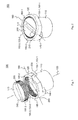
Fig. 4 zeigt eine perspektivische Darstellung einer Hubsäule mit zwei Hubsäulenelementen, die als Profilelemente dienen und einem Profilgleiter, der die beiden Hubelemente zueinander linear führt; -
Fig. 5 zeigt eine perspektivische Darstellung der Hubsäule ausFig. 4 zur Illustration der Einstellbarkeit des Profilgleiters; -
Fig. 6 zeigt eine schematisch vereinfachte Darstellung einer Hubsäule gemäß einem Ausführungsbeispiel; und -
Fig. 7 zeigt ein Flussdiagramm eines Verfahrens gemäß einem Ausführungsbeispiel.
-
Fig. 1 shows an exploded perspective view of a profile slider according to an embodiment with a guide structure and an adjustment structure; -
Fig. 2 shows a perspective view of the inFig. 1 shown profile slider; -
Fig. 3 shows a view of the in theFig. 1 and 2 shown profile glides, -
Fig. 4 shows a perspective view of a lifting column with two Hubsäulenelementen that serve as profile elements and a profile slider, which leads the two lifting elements linear to each other; -
Fig. 5 shows a perspective view of the lifting columnFig. 4 to illustrate the adjustability of the profile slider; -
Fig. 6 shows a schematically simplified representation of a lifting column according to an embodiment; and -
Fig. 7 shows a flowchart of a method according to an embodiment.
Bei der nachfolgenden Beschreibung der beigefügten Darstellungen bezeichnen gleiche Bezugszeichen gleiche oder vergleichbare Komponenten. Ferner werden zusammenfassende Bezugszeichen für Komponenten und Objekte verwendet, die mehrfach in einem Ausführungsbeispiel oder in einer Darstellung auftreten, jedoch hinsichtlich eines oder mehrerer Merkmale gemeinsam beschrieben werden. Komponenten oder Objekte, die mit gleichen oder zusammenfassenden Bezugszeichen beschrieben werden, können hinsichtlich einzelner, mehrerer oder aller Merkmale, beispielsweise ihrer Dimensionierungen, gleich, jedoch gegebenenfalls auch unterschiedlich ausgeführt sein, sofern sich aus der Beschreibung nicht etwas anderes explizit oder implizit ergibt.In the following description of the accompanying drawings, like reference characters designate like or similar components. Further, summary reference numbers are used for components and objects that occur multiple times in one embodiment or in one representation, but are described together in terms of one or more features. Components or objects which are described by the same or by the same reference numerals may be the same, but possibly also different, in terms of individual, several or all features, for example their dimensions, unless otherwise explicitly or implicitly stated in the description.
Wie bereits eingangs kurz erwähnt wurde, werden in vielen Bereichen der Technik Profilelemente zum Tragen, Ausrichten oder Bewegen von Komponenten, Objekten, Tieren oder Menschen verwendet. Bei den Profilelementen kann es sich beispielsweise um Profilrohre, Hubsäulenelemente oder andere profilierte Bauteile handeln. Diese können beispielsweise eine größte Abmessung in einer Haupterstreckungsuchtung aufweisen. Entlang dieser Haupterstreckungsuchtung können die Profilelemente beispielsweise eine zumindest abschnittsweise gleichmäßig ausgestaltete Profilierung oder ein gleichmäßig ausgestaltetes Profil aufweisen.As already briefly mentioned, in many fields of technology profile elements are used for carrying, aligning or moving components, objects, animals or humans. The profile elements may be, for example, profile tubes, Hubsäulenelemente or other profiled components. These may, for example, have a largest dimension in a main extension. Along this main extension, the profile elements can have, for example, a profiling which is uniformly configured at least in sections or a uniformly configured profile.
Je nach konkreter Implementierung kann das Profil beispielsweise eine Führungsnut umfassen, mit deren Hilfe eine Führung eines Profilelements bezogen auf ein weiteres Profilelement möglich ist. Je nach konkreter Implementierung kann hierbei beispielsweise eine Gleitlagerung eingesetzt werden.Depending on the specific implementation, the profile may include, for example, a guide groove, with the help of a guide a profile element based on another profile element is possible. Depending on the specific implementation, for example, a slide bearing can be used here.
Eine solche kann beispielsweise mit Hilfe von einem oder mehreren Profilgleitern umgesetzt werden. Diese können für die Führung von teleskopischen Profilrohren oder anderen Hubsäulenelementen eingesetzt werden, um nur zwei Beispiele zu nennen. Die betreffenden Profilelemente weisen hierbei häufig fertigungsbedingt oder aufgrund anderer Randbedingungen Variationen hinsichtlich ihrer Ausgestaltung auf, die beispielsweise dazu führen, dass die einzelnen Profilelemente im Rahmen der spezifizierten Toleranzen voneinander abweichen. Aufgrund dieser Variationen kann es, wenn diese nicht bei der Montage berücksichtigt und ggf. ausgeglichen werden, zu Zuverlässigkeitsproblemen bzw. Funktionen hinsichtlich der Funktionalität eines Systems kommen, welches die genannten Profilelemente umfasst. Alternativ oder ergänzend kann es auch zu einer Geräuschentwicklung kommen, die zwar hinsichtlich der Funktion unkritisch ist, jedoch von Benutzern als unangenehm bzw. als auf einen drohenden Ausfall hindeutend missverstanden werden könnten.Such can be implemented, for example, with the help of one or more profile glides. These can be used for the guidance of telescopic profile tubes or other Hubsäulenelementen, to name just two examples. The respective profile elements in this case often have manufacturing or due to other constraints variations in terms of their design, for example, lead to the fact that the individual profile elements differ from each other within the specified tolerances. Due to these variations, if these are not taken into account during assembly and, if necessary, compensated for, reliability problems or functions with regard to the functionality of a system which comprises the profile elements mentioned can occur. Alternatively or additionally, it may also lead to a noise, which is not critical in terms of function, but could be misunderstood by users as unpleasant or as pointing to an impending failure.
Konventionell werden so verschiedene Profilgleiter mit unterschiedlichen Breiten vorgesehen, um unterschiedliche Variationen bzw. Toleranzen ausgleichen zu können.Conventionally, different profile sliders with different widths are provided in order to be able to compensate for different variations or tolerances.
Wie die nachfolgende Erörterung noch zeigen wird, kann mit Hilfe eines einstellbaren Profilgleiters gemäß einem Ausführungsbeispiel eine ggf. sogar spielfreie Montage in einem Profilrohr oder einem anderen Profilelement erzielt werden. Je nach konkreter Implementierung eines solchen einstellbaren Profilgleiters, können diese einen bestimmten Bereich eines Toleranzfeldes zwischen den Führungsflächen, die auch als Gleitflächen bezeichnet werden, in den Profilelementen und beispielsweise einem Winkelversatz einer Profilnut ausgleichen. Dadurch kann ggf. eine Spielfreiheit in einem Profilelementsatz, also beispielsweise einem Profilrohrsatz, erreicht werden, ohne dass unterschiedlich breite Profilgleiter eingesetzt werden müssen. Ein solcher Profilgleiter kann beispielsweise aus zwei Kunststoffteilen gefertigt sein, wie die nachfolgende Beschreibung noch zeigen wird, und damit beispielsweise eine Vielfalt der einzelnen unterschiedlich breiten Einzelprofilgleitern reduzieren.As the following discussion will show, with the aid of an adjustable profile slider according to one embodiment, an optionally even backlash-free mounting in a profile tube or another profile element can be achieved. Depending on the concrete implementation of such an adjustable profile slide, they can compensate for a certain range of a tolerance field between the guide surfaces, which are also referred to as sliding surfaces in the profile elements and, for example, an angular offset of a profile groove. As a result, if necessary, a backlash in a profile element set, so for example a profile tube set, can be achieved without having to use different width profile glides. Such a profile slider may for example be made of two plastic parts, as the following description will show, and thus reduce, for example, a variety of individual different width single profile sliders.
Auch wenn in der nachfolgenden Beschreibung der Fokus auf dem Einsatz einstellbarer Profilgleiter für Hubsäulen liegt, also Hubsäulen mit einem integrierten Gleitsystem, können Ausführungsbeispiele eines Profilgleiters auch bei anderen Systemen, Baugruppen und Komponenten eingesetzt werden, bei denen eine lineare Bewegung zwischen zwei Profilelementen geführt werden soll. Diese Bewegung kann beispielsweise mit Hilfe eines Aktuatorsystems, die auch als Antriebseinheit bezeichnet wird, hervorgerufen werden.Although in the following description the focus is on the use of adjustable profile slide for lifting columns, so lifting columns with an integrated sliding system can Embodiments of a profile slider are also used in other systems, assemblies and components in which a linear movement between two profile elements to be performed. This movement can be caused for example by means of an actuator system, which is also referred to as a drive unit.
Anders ausgedrückt kann, auch wenn im Nachfolgenden der Fokus der Beschreibung auf Hubsäulen liegt, ein einstellbarer Profilgleiter in sehr vielen unterschiedlichen Systemen zum Einsatz gebracht werden.In other words, even though the focus of the description hereinafter is on lifting columns, an adjustable profile slider can be used in many different systems.
Ein Profilgleiter kann so beispielsweise für eine lineare Führung, also eine Linearführung herangezogen werden. Hierbei ist zu beachten, dass auch bei einer Linearführung bzw. linearen Führung durchaus nicht lineare Bewegungen umfasst sein können, wenn beispielsweise die betreffenden Strukturen zur Führung gebogen oder andere entsprechende Konturen aufweisen. Profilgleiter können jedoch auch zur Lagerung von Drehbewegungen eingesetzt werden. Entsprechend können Lagerungen beispielsweise als Linearlager bzw. auch als Lager zum Führen von Drehbewegungen implementiert sein.A profile slider can be used for example for a linear guide, so a linear guide. It should be noted that even in the case of a linear guide or linear guide, non-linear movements can certainly be encompassed if, for example, the relevant structures are bent to guide or have other corresponding contours. But profile glides can also be used for the storage of rotational movements. Accordingly, bearings can be implemented, for example, as a linear bearing or as a bearing for guiding rotational movements.
Die Befestigungsstruktur 110 ist genauer gesagt bei dem hier gezeigten Beispiel eines Profilgleiters 100 hohlzylindrisch ausgeformt, kann jedoch beispielsweise nur abschnittsweise hohlzylindrisch bzw. auch vollzylindrisch ausgefüllt sein. Selbstverständlich können andere Beispiele von Profilgleitern 100 auch anders geformte Befestigungsstrukturen 110 aufweisen, mit deren Hilfe der betreffende Profilgleiter 100 dann in dem zugehörigen Profilelement befestig werden kann. So kann grundsätzlich die Befestigungsstruktur 110 jegliche Form annehmen, also beispielsweise eine polygonale Außenkontur, eine rechteckige, eine quadratische, eine dreieckige oder auch eine unregelmäßig geformte oder asymmetrische Außenkontor aufweisen. Gleiches kann ebenso für eine Innenkontur im Falle eines Hohlkörpers oder andere Komponenten der Oberfläche der Befestigungsstruktur 110 gelten.The mounting
Der Profilgleiter 100 weist darüber hinaus eine Führungsstruktur 120 auf, die im Wesentlichen ringförmig und entlang einer Hauptachse 130 der hohlzylindrischen Außenform der Befestigungsstruktur 110 derart versetzt angeordnet ist, dass auf die Führungsstruktur 120 bezüglich der Hauptachse 130 eine im vorliegenden Beispiel zweizählige Symmetrie aufweist.The
Die Führungsstruktur 120 ist hierbei über zwei diametral gegenüberliegende Verbindungsabschnitte 140-1 und 140-2 mit der Befestigungsstruktur 110 verbunden. Die Verbindungsabschnitte 140 stehen hierbei radial über die Außenfläche der Befestigungsstruktur 110 hervor und brechen so die vollständige Rotationssymmetrie der Befestigungsstruktur 110 des in
Die Führungsstruktur 120 weist eine im Wesentlichen zylinderförmige Außenkontur auf, die jedoch von zwei abgeflachten Bereichen 150-1, 150-2 unterbrochen wird. Im Bereich der abgeflachten Bereiche 150 weist so die Führungsstruktur 120 eine geringere Erstreckung senkrecht zu der Hauptachse 130 auf als außerhalb der abgeflachten Bereiche 150. Die abgeflachten Bereiche 150 bilden hierbei zwei Gleitflächen 160-1, 160-2, die mit entsprechenden Führungsflächen einer Führungsnut eines Profilelements in Kontakt gebracht werden können. Hierzu kann eine Einstellstruktur 170 verwendet werden, die nachfolgende noch näher beschrieben wird.The
Die Einstellstruktur 170 sowie der Führungsabschnitt 120 weisen hierbei jeweils eine Verzahnungsstruktur 180-1 (an der Führungsstruktur 120) und 180-2 (an der Einstellstruktur 170) auf. Die Verzahnungsstrukturen 180 sind hierbei gerade so ausgestaltet, dass diese ineinander eingreifen können und so einen Abstand der Gleitflächen 160 voneinander einstellbar machen können.In this case, the
Anders ausgedrückt weist die Führungsstruktur 120 an ihrer Innenkontur die Verzahnungsstruktur 180-1 auf, die auch nur als Verzahnung bezeichnet wird, wobei die Führungsstruktur 120 gerade den Außenteil des Profilgleiters 100 bildet.In other words, the
Die Einstellstruktur 170 wird entsprechend auch als Innenteil bezeichnet und weist ebenfalls die bereits zuvor genannte Verzahnung bzw. Verzahnungsstruktur 180-2 auf, die jedoch an einer Außenkontur der Einstellstruktur 170 angeordnet ist. Die Außenkontur der Einstellstruktur 170 ist hierbei unrund ausgestaltet, weist also entlang einer Richtung, die senkrecht zu der Hauptachse 130 liegt bei der in
In noch anderen Worten ausgedrückt, weist die Einstellstruktur 170 aufgrund ihrer unrunden Form entlang einer Richtung senkrecht zu der Hauptachse 130 eine Erstreckung, einen Radius oder einen Durchmesser auf, der größer ist als senkrecht zu den beiden vorgenannten Richtungen.In other words, due to its non-circular shape along a direction perpendicular to the
Durch diese Ausgestaltung der Einstellstruktur 170 kann so bei einer Drehung derselben um die Hauptachse 130 ein Bereich der Einstellstruktur 170 in den Bereich der den Gleitflächen 160 innen gegenüberliegenden Teilen der Verzahnungsstruktur 180-1 gebracht werden, die einen größeren Abstand von der Hauptachse 130 haben als andere Teile der Verzahnungsstruktur 180-2 der Einstellstruktur 170. Dadurch kann so eine Kraft von innen auf die Führungsstruktur 120 und insbesondere auf die Gleitflächen 160 ausgeübt werden, über die der Profilgleiter an den Abstand der in der
Um dies zu erreichen, kann optional die Führungsstruktur 120 aus einem elastischen Werkstoff, beispielsweise einem elastischen Kunststoff gefertigt sein. Wie in
Durch diese zuvor beschriebene Ausgestaltung des Profilgleiters 100 kann so mit Hilfe der Einstellstruktur 170 und der entsprechenden Ausgestaltung der Führungsstruktur 120 ausgehend von einer Grundstellung, in der die Gleitflächen 160, einen kleinsten Abstand voneinander aufweisen, der Abstand zwischen diesen Gleitflächen vergrößert werden. Hierbei kann der Profilgleiter 100 symmetrisch zu einer Bewegungsrichtung 190 ausgestaltet sein. Die Bewegungsrichtung 190 verläuft hierbei senkrecht zu der Hauptachse 130 und im Wesentlichen parallel zu beiden Gleitflächen 160 bei dem in
Weist auch die Einstellstruktur 170 eine entsprechende symmetrische Ausgestaltung bezüglich einer Symmetrieachse auf, die senkrecht zu der Hauptachse 130 liegt, jedoch aufgrund der Drehbarkeit der Einstellstruktur 170 nicht mit der Bewegungsrichtung 190 des Profilgleiters 100 übereinstimmen muss, auf, kann so die voran beschriebene Symmetrie ggf. auch bei allen Einstellbedingungen des Profilgleiters 100, also bei allen Winkelstellungen der Einstellstruktur 170 bezogen auf die Führungsstruktur 120 realisiert werden.If the
Die Einstellstruktur 170 weist in einem Kopfbereich 200, der an seiner Außenflanke bzw. Außenkontur ebenso die Verzahnungsstruktur 180-2 trägt, eine Ausnehmung 210, die länglich ausgestaltet ist und beispielsweise zur Aufnahme eines Schraubenzieherkopfs ausgebildet sein kann. Die Richtung der Erstreckung der Ausnehmung 210 kann hierbei beispielsweise mit der größten Erstreckung der unrunden Außenkontur der Einstellstruktur 170 einhergehen bzw. zu dieser korrespondieren, um so während der Montage einen Hinweis auf den Grad der Abstandsvergrößerung zwischen den Gleitflächen 160 zu bieten. Hierdurch kann es also beispielsweise möglich sein, den Profilgleiter 100 auf den Abstand der in
Selbstverständlich kann bei anderen Beispielen eine Profilgleiters 100 auch eine andere Ausgestaltung der Ausnehmung 210 und eine andere Ausgestaltung einer entsprechenden Struktur der Einstellstruktur 170 erfolgen, über die die Einstellstruktur 170 bezogen auf die Führungsstruktur 120 im montierten Zustand drehbar und damit der Profilgleiter 100 einstellbar ist.Of course, in other examples, a
Die Einstellstruktur 170 weist darüber hinaus eine optionale Zentrierstruktur 220 auf, die bei dem hier gezeigten Beispiel einstückig bzw. einteilig mit dem Kopfbereich 200 verbunden ist. Die Zentrierstruktur 220 ist hier als Zylinderfortsatz ausgestaltet, der sich entlang der Hauptachse 130 in eine zentrale Ausnehmung 230 der Befestigungsstruktur 110 hinein erstreckt. Durch die Zentrierstruktur 220 und die zentrale Ausnehmung 230 kann so ggf. eine laterale Bewegung der Einstellstruktur 170 relativ zu der Führungsstruktur 120 unterbunden werden. Hierdurch kann ggf. die symmetrische Kraftentfaltung und die symmetrische Ausgestaltung der Führungsstruktur 120 mit ihren Gleitflächen 160 verbessert werden.The
Nachfolgend wird in Zusammenhang mit
Durch diese beschriebene Ausgestaltung stellt eine Möglichkeit dar, wie ein Profilgleiter 100 in die Lage versetzt wird, entlang einer senkrecht zu der Bewegungsrichtung 190 verlaufenden Richtung bei einer entsprechenden Druckbeanspruchung im Wesentlichen formstabil zu sein. Einerseits stützen sich die seitlichen Abschnitte 250 bzw. die Gleitflächen 160 über die Einstellstruktur 170 aneinander ab und damit an den in den
Der zuvor beschriebene Gleiter umfasst so also zwei beispielsweise ellipsenförmig ausgestaltete Kunststoffteile, die in einem nicht eingebauten Zustand schmaler als die auch als Gleitnut bezeichnete Führungsnut der Profilelemente (Profilrohre) ist. Nach dem Einbau kann dann über ein Bohrung die auch als ein Innenteil bezeichnete Einstellstruktur 170 bezogen auf eine auch als Außenteil bezeichnete Führungsstruktur 120 verdreht werden, sodass die Gleitflächen 160 dabei breiter werden bzw. ihr Abstand sich vergrößert und somit auf die gegebene Profilnutbreite eingestellt werden kann.Thus, the slider described above thus comprises two, for example, elliptically shaped plastic parts which, in a non-installed state, are narrower than the guide groove of the profile elements (profile tubes), also referred to as sliding grooves. After installation, the adjusting
Selbstverständlich können bei anderen Beispielen eines Profilgleiters 100 die konstruktiven Ausgestaltungsmerkmale anders gewählt werden. So kann beispielsweise die Zahl der Befestigungsabschnitte 140, deren geometrische Ausgestaltung, Anordnung und andere Parameter verändert werden. Ebenso kann ggf. eine Implementierung der Verzahnungsstrukturen 180 entfallen. Ebenso kann auch eine Lösung implementiert werden, bei der gerade nicht die Einstellstruktur 170 zentriert im Inneren der Führungsstruktur 120 angeordnet ist. So können beispielsweise auch asymmetrisch implementierte Lösungen, bei denen eine Einstellung beispielsweise durch ein Verschieben und nicht durch ein Drehen der Einstellstruktur 170 erfolgen, implementiert werden.Of course, in other examples of a
Auch wenn
Das weitere Profilelement 310-2 weist wiederum Führungsnute 320-1, 320-2 auf, die sich entlang der Bewegungsrichtung 190 erstrecken, entlang derer die beiden Profilelemente 310 auch zueinander beweglich sind.The further profile element 310-2 in turn has guide grooves 320-1, 320-2, which extend along the direction of
Die Hubsäule 300 umfasst ferner einen oder mehrere Profilgleiter 100, wie diese beispielsweise zuvor beschrieben wurden. Bei der hier gezeigten Ausgestaltung der Hubsäule 300 in
Um nun eine Bewegbarkeit der Hubsäule 300 zu ermöglichen, weist diese ferner eine optionale Antriebseinheit 360 auf, die in der Lage ist, das Profilelement 310-1 bezogen auf das weitere Profilelement 310-2 entlang der Bewegungsrichtung 190 zu bewegen. Zu diesem Zweck weist die hier gezeigte Antriebseinheit 360 einen Motor 370 auf, bei dem sich beispielsweise um einen Elektromotor, jedoch auch um einen pneumatischen, hydraulischen oder anders betriebenen Motor handelt, der ausgebildet ist, um eine Welle 380 in eine Rotationsbewegung zu versetzen. Die Antriebseinheit 360 weist ferner ein Schraubgetriebe 390 auf, welches in der Lage ist, die Rotationsbewegung der Welle 380 in eine lineare Bewegung entlang der Bewegungsrichtung 190 umzusetzen. Das Schraubgetriebe 390 kann beispielsweise einen Spindelantrieb oder eine Schnecke umfassen. Selbstverständlich können jedoch auch andere Konstruktionen einer Antriebseinheit 360 verwendet werden.In order to enable a mobility of the
Der Einsatz eines einstellbaren Profilgleiters, wie er zuvor beschrieben wurde, kann in diesem Zusammenhang nicht nur eine ggf. einfachere Montage und eine Einsparung von Teilen ermöglichen, sodass unterschiedlich breite Profilgleiter ggf. vermieden werden können, die bei einer starren Konstruktion ggf. zu implementieren sind, es kann vielmehr auch aufgrund der ggf. möglichen spielfreien Implementierung eine durch den Motor 370 aufgeprägte Drehbewegung über eine Bodenplatte 400 abgegeben werden, ohne dass das Profilelement 310-1 bei der hier gezeigten Ausführung eine merkliche, spielbedingte Rotationsbewegung erhält. Die Bodenplatte 400 kann beispielsweise zur Aufnahme des Motors 370 jedoch auch zur Montage des weiteren Profilelements 310-2 dienen.The use of an adjustable profile slider, as described above, can in this context not only make possible simpler installation and a saving of parts, so that different width profile glides can possibly be avoided, which are possibly to implement in a rigid construction , It may also be due to the possibly possible backlash-free implementation imparted by the
Auch hier können selbstverständlich bei anderen Beispielen von Hubsäulen 300 andere konstruktive Ausgestaltungen gewählt werden.Again, of course, in other examples of lifting
Bei einem Ausführungsbeispiel eines Verfahrens können die zuvor genannten Verfahrensschritte in der angegebenen, jedoch auch gegebenenfalls in einer abweichenden Reihenfolge durchgeführt werden. So können gegebenenfalls einzelne Verfahrensschritte simultan, zumindest jedoch auch zeitlich überlappend erfolgen, sofern sich aus deren Beschreibung oder dem technischen Zusammenhang nichts anderes ergibt.In one embodiment of a method, the aforementioned method steps in the specified, but also optionally in a different order can be performed. Thus, if appropriate, individual process steps can take place simultaneously, but at least overlap in time, unless otherwise stated in the description or the technical context.
Durch den Einsatz eines Ausführungsbeispiels kann ggf. ein Kompromiss hinsichtlich herstellungsbedingter Variationen und einer möglichst einfachen Herstellung und Montage verbessert werden.By using an exemplary embodiment, a compromise can be improved, if necessary, with regard to production-related variations and the simplest possible manufacture and assembly.
Die in der vorstehenden Beschreibung, den nachfolgenden Ansprüchen und den beigefügten Figuren offenbarten Merkmale können sowohl einzeln wie auch in beliebiger Kombination für die Verwirklichung eines Ausführungsbeispiels in ihren verschiedenen Ausgestaltungen von Bedeutung sein und implementiert werden.The features disclosed in the foregoing description, the appended claims and the appended figures may be taken to be and effect both individually and in any combination for the realization of an embodiment in its various forms.
- 100100
- Profilgleiterprofile Glide
- 110110
- Befestigungsstrukturattachment structure
- 120120
- Führungsstrukturmanagement structure
- 130130
- Hauptachsemain axis
- 140140
- Verbindungsabschnittconnecting portion
- 150150
- abgeflachter Bereichflattened area
- 160160
- Gleitflächesliding surface
- 170170
- Einstellstruktursetting structure
- 180180
- Verzahnungsstrukturtoothing structure
- 190190
- Bewegungsrichtungmovement direction
- 200200
- Kopfbereichhead area
- 210210
- Ausnehmungrecess
- 220220
- Zentrierstrukturcentering structure
- 230230
- zentrierte Ausnehmungcentered recess
- 240240
- Drehungrotation
- 250250
- seitlicher Abschnittlateral section
- 300300
- HubsäuleLifting column
- 310310
- Profilelementprofile element
- 320320
- Führungsnutguide
- 330330
- Befestigungsausnehmungmounting recess
- 340340
- Führungsflächeguide surface
- 350350
- Einstellöffnunginsertion opening
- 360360
- Antriebseinheitdrive unit
- 370370
- Motorengine
- 380380
- Wellewave
- 390390
- Schraubgetriebehelical
- 400400
- Bodenplattebaseplate
Claims (10)
Applications Claiming Priority (1)
| Application Number | Priority Date | Filing Date | Title |
|---|---|---|---|
| DE102014207930.6A DE102014207930A1 (en) | 2014-04-28 | 2014-04-28 | Profile glider, lifting column and method for mounting a lifting column |
Publications (1)
| Publication Number | Publication Date |
|---|---|
| EP2940326A1 true EP2940326A1 (en) | 2015-11-04 |
Family
ID=53052676
Family Applications (1)
| Application Number | Title | Priority Date | Filing Date |
|---|---|---|---|
| EP15164636.1A Withdrawn EP2940326A1 (en) | 2014-04-28 | 2015-04-22 | Profile slider, lifting column and method for assembling a lifting column |
Country Status (3)
| Country | Link |
|---|---|
| US (1) | US20150308496A1 (en) |
| EP (1) | EP2940326A1 (en) |
| DE (1) | DE102014207930A1 (en) |
Citations (4)
| Publication number | Priority date | Publication date | Assignee | Title |
|---|---|---|---|---|
| EP0651167A1 (en) * | 1993-10-28 | 1995-05-03 | Josef Scheppach Maschinenfabrik GmbH & Co. | Adjustable longitudinal guide for machine units |
| DE19825806A1 (en) * | 1997-06-09 | 1998-12-10 | Sears Mfg Co | Adjustable storage system |
| EP1004784A1 (en) * | 1998-11-23 | 2000-05-31 | Magnetic Elektromotoren A.G. Liestal | Lifting post |
| AT507016A1 (en) * | 2008-07-11 | 2010-01-15 | Pkt Praez Skunststofftechnik B | LINEAR GUIDE |
Family Cites Families (5)
| Publication number | Priority date | Publication date | Assignee | Title |
|---|---|---|---|---|
| DE9209738U1 (en) * | 1992-07-20 | 1993-02-25 | Kinshofer Greiftechnik Gmbh, 8176 Waakirchen, De | |
| DE19715014A1 (en) * | 1997-04-11 | 1998-10-15 | Schaeffler Waelzlager Ohg | Linear guide |
| JP3913598B2 (en) * | 2002-04-16 | 2007-05-09 | アイダエンジニアリング株式会社 | Slide guide device for press machine |
| CN200993160Y (en) * | 2006-05-16 | 2007-12-19 | 海顿直线电机(常州)有限公司 | Adjustable linear slider |
| DE102012215131A1 (en) * | 2012-08-24 | 2014-02-27 | Aktiebolaget Skf | Mounting plate and lifting column |
-
2014
- 2014-04-28 DE DE102014207930.6A patent/DE102014207930A1/en not_active Withdrawn
-
2015
- 2015-04-22 EP EP15164636.1A patent/EP2940326A1/en not_active Withdrawn
- 2015-04-28 US US14/698,344 patent/US20150308496A1/en not_active Abandoned
Patent Citations (4)
| Publication number | Priority date | Publication date | Assignee | Title |
|---|---|---|---|---|
| EP0651167A1 (en) * | 1993-10-28 | 1995-05-03 | Josef Scheppach Maschinenfabrik GmbH & Co. | Adjustable longitudinal guide for machine units |
| DE19825806A1 (en) * | 1997-06-09 | 1998-12-10 | Sears Mfg Co | Adjustable storage system |
| EP1004784A1 (en) * | 1998-11-23 | 2000-05-31 | Magnetic Elektromotoren A.G. Liestal | Lifting post |
| AT507016A1 (en) * | 2008-07-11 | 2010-01-15 | Pkt Praez Skunststofftechnik B | LINEAR GUIDE |
Also Published As
| Publication number | Publication date |
|---|---|
| DE102014207930A1 (en) | 2015-10-29 |
| US20150308496A1 (en) | 2015-10-29 |
Similar Documents
| Publication | Publication Date | Title |
|---|---|---|
| EP3209888B1 (en) | Quick fastener, method for connecting two components by means of the quick fastener and production method therefor | |
| EP2130722B1 (en) | Tolerance compensation element | |
| DE102012013979A1 (en) | Linaearaktuator and method for producing a linear actuator | |
| EP2334952A1 (en) | Spindle drive having anti-turn mechanism | |
| EP3302856A1 (en) | Tool clamping system | |
| EP2574799B1 (en) | Telescopic connection assembly | |
| DE102013004188A1 (en) | Coupling device and turbomachine | |
| EP3156564B1 (en) | Pin with adjustable length | |
| EP2704929B1 (en) | Locking mechanism | |
| EP2102509B1 (en) | Tie-rod and module arrangement clamped together thereto | |
| EP3572312B1 (en) | Centring element and steering device for a bicycle | |
| DE102017102535B4 (en) | Adjustment arrangement for adjusting a vehicle seat component, vehicle seat and method for producing an adjustment arrangement | |
| EP2940326A1 (en) | Profile slider, lifting column and method for assembling a lifting column | |
| EP2031175A1 (en) | Side section for a roller shutter housing | |
| EP2682543A2 (en) | Fitting device | |
| DE202013101539U1 (en) | Abstandsjustierelement | |
| DE102015213235B4 (en) | Rolling elements of a rolling bearing | |
| AT515491B1 (en) | Self-closing roller door hinge | |
| EP1793067B1 (en) | Fitting for doors, windows or the like | |
| EP3115294A1 (en) | Push-pull rod | |
| DE3219011C2 (en) | ||
| WO1999025995A1 (en) | Drive spindle | |
| EP1637771A2 (en) | Threaded drive unit | |
| DE102013221349A1 (en) | drive unit | |
| EP1114905A1 (en) | Mounting sleeve |
Legal Events
| Date | Code | Title | Description |
|---|---|---|---|
| PUAI | Public reference made under article 153(3) epc to a published international application that has entered the european phase |
Free format text: ORIGINAL CODE: 0009012 |
|
| AK | Designated contracting states |
Kind code of ref document: A1 Designated state(s): AL AT BE BG CH CY CZ DE DK EE ES FI FR GB GR HR HU IE IS IT LI LT LU LV MC MK MT NL NO PL PT RO RS SE SI SK SM TR |
|
| AX | Request for extension of the european patent |
Extension state: BA ME |
|
| STAA | Information on the status of an ep patent application or granted ep patent |
Free format text: STATUS: THE APPLICATION IS DEEMED TO BE WITHDRAWN |
|
| 18D | Application deemed to be withdrawn |
Effective date: 20160505 |