EP2940291A1 - Axial piston motor - Google Patents
Axial piston motor Download PDFInfo
- Publication number
- EP2940291A1 EP2940291A1 EP13868490.7A EP13868490A EP2940291A1 EP 2940291 A1 EP2940291 A1 EP 2940291A1 EP 13868490 A EP13868490 A EP 13868490A EP 2940291 A1 EP2940291 A1 EP 2940291A1
- Authority
- EP
- European Patent Office
- Prior art keywords
- nozzle
- cylinder block
- cylinder
- housing
- drive shaft
- Prior art date
- Legal status (The legal status is an assumption and is not a legal conclusion. Google has not performed a legal analysis and makes no representation as to the accuracy of the status listed.)
- Withdrawn
Links
Images



Classifications
-
- F—MECHANICAL ENGINEERING; LIGHTING; HEATING; WEAPONS; BLASTING
- F04—POSITIVE - DISPLACEMENT MACHINES FOR LIQUIDS; PUMPS FOR LIQUIDS OR ELASTIC FLUIDS
- F04B—POSITIVE-DISPLACEMENT MACHINES FOR LIQUIDS; PUMPS
- F04B1/00—Multi-cylinder machines or pumps characterised by number or arrangement of cylinders
- F04B1/12—Multi-cylinder machines or pumps characterised by number or arrangement of cylinders having cylinder axes coaxial with, or parallel or inclined to, main shaft axis
- F04B1/20—Multi-cylinder machines or pumps characterised by number or arrangement of cylinders having cylinder axes coaxial with, or parallel or inclined to, main shaft axis having rotary cylinder block
- F04B1/2014—Details or component parts
- F04B1/2078—Swash plates
-
- F—MECHANICAL ENGINEERING; LIGHTING; HEATING; WEAPONS; BLASTING
- F03—MACHINES OR ENGINES FOR LIQUIDS; WIND, SPRING, OR WEIGHT MOTORS; PRODUCING MECHANICAL POWER OR A REACTIVE PROPULSIVE THRUST, NOT OTHERWISE PROVIDED FOR
- F03C—POSITIVE-DISPLACEMENT ENGINES DRIVEN BY LIQUIDS
- F03C1/00—Reciprocating-piston liquid engines
- F03C1/02—Reciprocating-piston liquid engines with multiple-cylinders, characterised by the number or arrangement of cylinders
- F03C1/06—Reciprocating-piston liquid engines with multiple-cylinders, characterised by the number or arrangement of cylinders with cylinder axes generally coaxial with, or parallel or inclined to, main shaft axis
- F03C1/0602—Component parts, details
-
- F—MECHANICAL ENGINEERING; LIGHTING; HEATING; WEAPONS; BLASTING
- F03—MACHINES OR ENGINES FOR LIQUIDS; WIND, SPRING, OR WEIGHT MOTORS; PRODUCING MECHANICAL POWER OR A REACTIVE PROPULSIVE THRUST, NOT OTHERWISE PROVIDED FOR
- F03C—POSITIVE-DISPLACEMENT ENGINES DRIVEN BY LIQUIDS
- F03C1/00—Reciprocating-piston liquid engines
- F03C1/02—Reciprocating-piston liquid engines with multiple-cylinders, characterised by the number or arrangement of cylinders
- F03C1/06—Reciprocating-piston liquid engines with multiple-cylinders, characterised by the number or arrangement of cylinders with cylinder axes generally coaxial with, or parallel or inclined to, main shaft axis
- F03C1/0636—Reciprocating-piston liquid engines with multiple-cylinders, characterised by the number or arrangement of cylinders with cylinder axes generally coaxial with, or parallel or inclined to, main shaft axis having rotary cylinder block
- F03C1/0644—Component parts
-
- F—MECHANICAL ENGINEERING; LIGHTING; HEATING; WEAPONS; BLASTING
- F03—MACHINES OR ENGINES FOR LIQUIDS; WIND, SPRING, OR WEIGHT MOTORS; PRODUCING MECHANICAL POWER OR A REACTIVE PROPULSIVE THRUST, NOT OTHERWISE PROVIDED FOR
- F03C—POSITIVE-DISPLACEMENT ENGINES DRIVEN BY LIQUIDS
- F03C1/00—Reciprocating-piston liquid engines
- F03C1/02—Reciprocating-piston liquid engines with multiple-cylinders, characterised by the number or arrangement of cylinders
- F03C1/06—Reciprocating-piston liquid engines with multiple-cylinders, characterised by the number or arrangement of cylinders with cylinder axes generally coaxial with, or parallel or inclined to, main shaft axis
- F03C1/0636—Reciprocating-piston liquid engines with multiple-cylinders, characterised by the number or arrangement of cylinders with cylinder axes generally coaxial with, or parallel or inclined to, main shaft axis having rotary cylinder block
- F03C1/0644—Component parts
- F03C1/0652—Cylinders
-
- F—MECHANICAL ENGINEERING; LIGHTING; HEATING; WEAPONS; BLASTING
- F03—MACHINES OR ENGINES FOR LIQUIDS; WIND, SPRING, OR WEIGHT MOTORS; PRODUCING MECHANICAL POWER OR A REACTIVE PROPULSIVE THRUST, NOT OTHERWISE PROVIDED FOR
- F03C—POSITIVE-DISPLACEMENT ENGINES DRIVEN BY LIQUIDS
- F03C1/00—Reciprocating-piston liquid engines
- F03C1/02—Reciprocating-piston liquid engines with multiple-cylinders, characterised by the number or arrangement of cylinders
- F03C1/06—Reciprocating-piston liquid engines with multiple-cylinders, characterised by the number or arrangement of cylinders with cylinder axes generally coaxial with, or parallel or inclined to, main shaft axis
- F03C1/0636—Reciprocating-piston liquid engines with multiple-cylinders, characterised by the number or arrangement of cylinders with cylinder axes generally coaxial with, or parallel or inclined to, main shaft axis having rotary cylinder block
- F03C1/0644—Component parts
- F03C1/0663—Casings, housings
-
- F—MECHANICAL ENGINEERING; LIGHTING; HEATING; WEAPONS; BLASTING
- F03—MACHINES OR ENGINES FOR LIQUIDS; WIND, SPRING, OR WEIGHT MOTORS; PRODUCING MECHANICAL POWER OR A REACTIVE PROPULSIVE THRUST, NOT OTHERWISE PROVIDED FOR
- F03C—POSITIVE-DISPLACEMENT ENGINES DRIVEN BY LIQUIDS
- F03C1/00—Reciprocating-piston liquid engines
- F03C1/02—Reciprocating-piston liquid engines with multiple-cylinders, characterised by the number or arrangement of cylinders
- F03C1/06—Reciprocating-piston liquid engines with multiple-cylinders, characterised by the number or arrangement of cylinders with cylinder axes generally coaxial with, or parallel or inclined to, main shaft axis
- F03C1/0636—Reciprocating-piston liquid engines with multiple-cylinders, characterised by the number or arrangement of cylinders with cylinder axes generally coaxial with, or parallel or inclined to, main shaft axis having rotary cylinder block
- F03C1/0644—Component parts
- F03C1/0668—Swash or actuated plate
-
- F—MECHANICAL ENGINEERING; LIGHTING; HEATING; WEAPONS; BLASTING
- F04—POSITIVE - DISPLACEMENT MACHINES FOR LIQUIDS; PUMPS FOR LIQUIDS OR ELASTIC FLUIDS
- F04B—POSITIVE-DISPLACEMENT MACHINES FOR LIQUIDS; PUMPS
- F04B1/00—Multi-cylinder machines or pumps characterised by number or arrangement of cylinders
- F04B1/12—Multi-cylinder machines or pumps characterised by number or arrangement of cylinders having cylinder axes coaxial with, or parallel or inclined to, main shaft axis
- F04B1/122—Details or component parts, e.g. valves, sealings or lubrication means
-
- F—MECHANICAL ENGINEERING; LIGHTING; HEATING; WEAPONS; BLASTING
- F04—POSITIVE - DISPLACEMENT MACHINES FOR LIQUIDS; PUMPS FOR LIQUIDS OR ELASTIC FLUIDS
- F04B—POSITIVE-DISPLACEMENT MACHINES FOR LIQUIDS; PUMPS
- F04B1/00—Multi-cylinder machines or pumps characterised by number or arrangement of cylinders
- F04B1/12—Multi-cylinder machines or pumps characterised by number or arrangement of cylinders having cylinder axes coaxial with, or parallel or inclined to, main shaft axis
- F04B1/20—Multi-cylinder machines or pumps characterised by number or arrangement of cylinders having cylinder axes coaxial with, or parallel or inclined to, main shaft axis having rotary cylinder block
- F04B1/2014—Details or component parts
- F04B1/2035—Cylinder barrels
-
- F—MECHANICAL ENGINEERING; LIGHTING; HEATING; WEAPONS; BLASTING
- F04—POSITIVE - DISPLACEMENT MACHINES FOR LIQUIDS; PUMPS FOR LIQUIDS OR ELASTIC FLUIDS
- F04B—POSITIVE-DISPLACEMENT MACHINES FOR LIQUIDS; PUMPS
- F04B1/00—Multi-cylinder machines or pumps characterised by number or arrangement of cylinders
- F04B1/12—Multi-cylinder machines or pumps characterised by number or arrangement of cylinders having cylinder axes coaxial with, or parallel or inclined to, main shaft axis
- F04B1/20—Multi-cylinder machines or pumps characterised by number or arrangement of cylinders having cylinder axes coaxial with, or parallel or inclined to, main shaft axis having rotary cylinder block
- F04B1/2014—Details or component parts
- F04B1/2064—Housings
-
- F—MECHANICAL ENGINEERING; LIGHTING; HEATING; WEAPONS; BLASTING
- F04—POSITIVE - DISPLACEMENT MACHINES FOR LIQUIDS; PUMPS FOR LIQUIDS OR ELASTIC FLUIDS
- F04B—POSITIVE-DISPLACEMENT MACHINES FOR LIQUIDS; PUMPS
- F04B53/00—Component parts, details or accessories not provided for in, or of interest apart from, groups F04B1/00 - F04B23/00 or F04B39/00 - F04B47/00
- F04B53/18—Lubricating
Definitions
- the present invention relates to an axial piston motor.
- this axial piston motor includes a housing 100, a drive shaft 101 mounted to the housing 100 so as to be freely rotatable, a cylinder block 102 fixed to the drive shaft 101, a piston 103 fitted into a cylinder 102a of the cylinder block 102 so as to be capable of freely advancing and retreating, and a swash plate 104 supporting the piston 103 through a shoe 105.
- the piston is reciprocally moved by supplying operation oil to the cylinder 102a. Then, the cylinder block 102 and the drive shaft 101 are rotated by reciprocally moving the piston 103.
- the centrifugal force affects the contact pressure, and the heating value generated on the inner surface of the cylinder 102a becomes large. Accordingly, the operation oil escaped into the clearance cannot sufficiently cool the inner surface of the cylinder 102a. Further, as the centrifugal force increases, the piston 103 is pressed outward in a radial direction, and a width of the clearance on an outer side of the piston 103 in the radial direction is narrowed.
- Patent Document 1 Japanese Patent No. 4828371
- an object of the present invention is to provide an axial piston motor which is capable of preventing seizure of a piston and seizure of a cylinder and operating a cylinder block at high speed rotation and which is capable of preventing deterioration of performance due to an increase in an amount of operation oil leaked from the cylinder.
- an axial piston motor comprising:
- the nozzle for jetting operation oil is provided at the position opposite to the outer circumferential surface of the cylinder block.
- the cylinder block can be operated at high speed rotation. Further, since the seizure of the piston and the seizure of the cylinder can be prevented without increasing a clearance between the piston and the cylinder, deterioration of performance due to an increase in an amount of the operation oil leaked from the cylinder can be prevented.
- the outer circumferential surface of the cylinder block has a high temperature zone which has a temperature higher than a predetermined threshold value during rotation of the cylinder block, and the nozzle is opposed to the high temperature zone of the cylinder block.
- the threshold value is a value in which seizure of at least one of the piston and the cylinder can occur between during the rotation of the cylinder block.
- the operation oil can be sprayed from the nozzle to the high temperature zone, and the seizure of the piston and the seizure of the cylinder can be reliably prevented.
- the high temperature zone of the cylinder block is in a set range where a center angle is from +40° to -40° when a bottom dead center of the piston is selected as a standard.
- a positive direction of the center angle is a rotation direction of the cylinder block.
- the high temperature zone becomes a zone where seizure can occur the most, the high temperature zone is in the set range. Therefore, the seizure can be reliably prevented by the jetting of the operation oil from the nozzle.
- the nozzle is disposed outside the position at which the piston is at the bottom dead center in a radial direction, and as viewed in the axial direction of the drive shaft, a jetting direction of the nozzle intersects the set range of the cylinder block.
- the nozzle since the nozzle is disposed outside the position where the piston is at the bottom dead center in the radial direction, and the jetting direction of the nozzle intersects the set range of the cylinder block, the nozzle can be disposed at the appropriate position.
- the axial piston motor further comprises a plug screwed to the housing in a penetrated state, wherein the plug has the nozzle.
- the attachment and removal of the nozzle to and from the housing can be easily performed by attaching and removing the plug to and from the housing.
- the housing has a pair of main passages, which is connected to the cylinder and supplies and discharges the operation oil to the cylinder and a flushing valve, which is switched by pressure difference between the pair of main passages and guides the operation oil passing through the main passage on a low pressure side to the nozzle, is provided at the housing.
- the motor can be made compact.
- the nozzle for jetting operation oil is provided at the position opposite to the outer circumferential surface of the cylinder block.
- Fig. 1 is sectional view illustrating an axial piston motor of one embodiment of this invention. As illustrated in Fig. 1 , this motor includes a housing 1, a drive shaft 3 mounted to this housing 1 through a bearing 2 so as to be freely rotatable, and a cylinder block 4 fixed to this drive shaft 3.
- the cylinder block 4 has a plurality of cylinders 40 arrayed in a circumferential direction.
- a plurality of pistons 5 is fitted into this plurality of cylinders 40 so as to be capable of freely advancing and retreating.
- a tip part of the piston 5 is formed in a spherical shape and coupled to a shoe 6.
- This shoe 6 is supported by a swash plate 7 positioned relatively to the housing 1.
- This swash plate 7 has a tiltable surface relative to the drive shaft 3, and supports the plurality of pistons 5 by the tilted surface.
- a tilting angle of this swash plate 7 relative to the drive shaft 3 is adjusted by a first control piston 81 and a second control piston 82.
- the housing 1 has a cover 10 covering an end part side of the drive shaft 3.
- a port 40a for supplying and discharging the operation oil to an inside of the cylinder 40 is formed at a bottom part of each cylinder 40.
- An end surface of the cylinder block 4 is in contact with the valve plate 9.
- the first main passage 11 of the cover 10, the first port 91 of the valve plate 9, and the port 40a of the predetermined cylinder 40 communicate with one another.
- the second main passage 12 of the cover 10, the second port 92 of the valve plate 9, and the port 40a of the predetermined cylinder 40 communicate with one another.
- a nozzle 21 for jetting the operation oil is arranged on an inner surface of the housing 1 and is provided at a position opposite to an outer circumferential surface of the cylinder block 4. This nozzle 21 is provided at a tip part of a plug 20. This plug 20 is screwed to the housing 1 in a penetrated state.
- the nozzle 21 faces a nozzle passage 15 provided at the housing 1, and the nozzle passage 15 is connected to a flushing valve 30 provided at the cover 10 of the housing 1.
- This flushing valve 30 is connected to a first sub-passage 13 communicated with the first main passage 11 and is connected to a second sub-passage 14 communicated with the second main passage 12.
- This flushing valve 30 is switched by pressure difference between the first main passage 11 and the second main passage 12, and the operation oil passing through the main passage on a low pressure side is guided to the nozzle 21 via the nozzle passage 15.
- an outer circumferential surface of the cylinder block 4 has a high temperature zone Z where a temperature can be higher than a predetermined threshold value during rotation of the cylinder block 4.
- the threshold value is a value in which seizure of at least one of the piston 5 and the cylinder 40 can occur between during the rotation of the cylinder block 4.
- the high temperature zone Z of the cylinder block 4 is in a set range R where a center angle is from +40° to -40° when a position L, at which the piston 5 is at a bottom dead center, is selected as a standard.
- a positive direction of the center angle is a rotation direction of the cylinder block 4.
- the bottom dead center of the piston 5 is a position where the piston 5 is protruded the most from the cylinder 40.
- a line connecting a center of the piston 5 and a center of the drive shaft 3, which represents the bottom dead center, is selected as a standard line B
- the set range R is a range where the center angle is from +40° to -40° around the standard line B.
- the nozzle 21 is opposed to the high temperature zone Z of the cylinder block 4. Specifically speaking, as viewed in the axial direction of the drive shaft 3, the nozzle 21 is disposed outside the position L at which the piston 5 is at the bottom dead center in a radial direction. As viewed in the axial direction of the drive shaft 3, a jetting direction of the nozzle 21 intersects the set range R of the cylinder block 4. As viewed in the axial direction of the drive shaft 3, the jetting direction of the nozzle 21 coincides with a radial direction of the cylinder block 4 (the standard line B).
- Fig. 3 illustrates a circuit diagram of the motor.
- the first main passage 11 and the second main passage 12 are connected to a motor unit 50 including the drive shaft 3, the cylinder block 4, the piston 5, and the swash plate 7.
- the first sub-passage 13 branched from the first main passage 11 is connected to a first port P1 of a spool 31 of the flushing valve 30, and the second sub-passage 14 branched from the second main passage 12 is connected to a second port P2 of the spool 31.
- the nozzle passage 15 faced by the nozzle 21 is connected to a third port P3 of the spool 31.
- the spool 31 is switched from the first position S1 to the second position S2 by a differential pressure between the high pressure operation oil in the first sub-passage 13 and the low pressure operation oil in the second sub-passage 14, and the second sub-passage 14 communicates with the nozzle passage 15.
- the low pressure operation oil in the second sub-passage 14 can be jetted from the nozzle 21 to the motor unit 50.
- the spool 31 is switched from the first position S1 to the third position S3 by a differential pressure between the high pressure operation oil in the second sub-passage 14 and the low pressure operation oil in the first sub-passage 13, and the first sub-passage 13 communicates with the nozzle passage 15.
- the low pressure operation oil in the first sub-passage 13 can be jetted from the nozzle 21 to the motor unit 50.
- the first and second control pistons 81, 82 may be driven by branching passages from the first sub-passage 13 and the second sub-passage 14 and flowing the operation oil into these pistons 81, 82 through the branch passages.
- Fig. 4 is a sectional view of the flushing valve 30.
- the spool 31 is fitted into a valve hole 32 provided at the cover 10 of the housing 1 so as to be freely slidable. Then, as illustrated by a solid arrow, when the high pressure operation oil is supplied to the first sub-passage 13, the spool 31 receives this high pressure operation oil and is moved to a right side in the drawing (the second position S2 in Fig. 3 ). As illustrated in dotted arrows, the low pressure operation oil is supplied from the second sub-passage 14 to the nozzle passage 15.
- the nozzle 21 for jetting operation oil is provided at the position opposite to the outer circumferential surface of the cylinder block 4.
- the cylinder block 4 can be operated at high speed rotation. Further, since the seizure of the piston 5 and the seizure of the cylinder 40 can be prevented without increasing a clearance between the piston 5 and the cylinder 40, deterioration of performance due to an increase in an amount of the operation oil leaked from the cylinder 40 can be prevented.
- the operation oil can be sprayed from the nozzle 21 to the high temperature zone Z, and the seizure of the piston 5 and the seizure of the cylinder 40 can be reliably prevented.
- the high temperature zone Z becomes a zone where seizure can occur the most, the high temperature zone Z is in the set range R. Accordingly, the seizure can be reliably prevented by the jetting of the operation oil from the nozzle 21.
- the nozzle 21 is disposed outside in the radial direction of the position L at which the piston 5 is at the bottom dead center, and the jetting direction of the nozzle 21 intersects the set range R of the cylinder block 4. Accordingly, the nozzle 21 is disposed at the appropriate position.
- the plug 20 is screwed to the housing 1, and the plug 20 has the nozzle 21. Accordingly, the attachment and removal of the nozzle 21 to and from the housing 1 can be easily performed by attaching and removing the plug 20 to and from the housing 1.
- the flushing valve 30 is provided at the housing 1, the motor can be made compact.
- the numbers of the piston 5 and the cylinder 40 may be increased and decreased.
- the number of the nozzle 21 may be increased and decreased.
- the set range R of the cylinder block 4 is a range where the center angle is from +40° to -40° around the standard line B.
- the set range R may be a range where the center angle is from +15° to -15° around the standard line B.
- the jetting direction of the nozzle 21 coincides with the radial direction of the cylinder block 4.
- the jetting direction may be tilted in the radial direction of the cylinder block 4.
- a specific numerical value of the set range R is not limited to this embodiment, and designs can be modified.
- the jetting direction of the nozzle 21 coincides with the direction (the radial direction) orthogonal to the axis of the drive shaft 3.
- a jetting direction of a nozzle 21 may be tilted in a range ⁇ of from +45° to -45° when a direction S orthogonal to an axis of a drive shaft 3 is selected as a standard.
- the nozzle 21 is a part of the plug 20.
- the nozzle 21 may be directly formed at the housing 1.
- the nozzle may be opposed to a zone other than the high temperature zone.
- the high temperature zone may be a range other than the range where the center angle is from +40° to -40°.
- the nozzle may be disposed outside a position other than the position where the piston is at the bottom dead center in the radial direction.
- the nozzle may be provided at a part other than the plug.
- the flushing valve may be omitted.
Landscapes
- Engineering & Computer Science (AREA)
- Mechanical Engineering (AREA)
- General Engineering & Computer Science (AREA)
- Chemical & Material Sciences (AREA)
- Combustion & Propulsion (AREA)
- Hydraulic Motors (AREA)
- Reciprocating Pumps (AREA)
- Lubrication Of Internal Combustion Engines (AREA)
Abstract
On an inner surface of a housing 1, a nozzle 21 for jetting operation oil is provided at a position opposite to an outer circumferential surface of a cylinder block 4. With this configuration, by spraying the operation oil from the nozzle 21 to the outer circumferential surface of the cylinder block 4 during rotation of the cylinder block 4, this operation oil can remove frictional heat generated by sliding between a piston 5 and a cylinder 40, and seizure of the piston 5 and seizure of the cylinder 40 can be prevented.
Description
- The present invention relates to an axial piston motor.
- Conventionally, there has been an axial piston motor described in Japanese Patent No.
4828371 Fig. 6 , this axial piston motor includes ahousing 100, adrive shaft 101 mounted to thehousing 100 so as to be freely rotatable, acylinder block 102 fixed to thedrive shaft 101, apiston 103 fitted into acylinder 102a of thecylinder block 102 so as to be capable of freely advancing and retreating, and aswash plate 104 supporting thepiston 103 through ashoe 105. The piston is reciprocally moved by supplying operation oil to thecylinder 102a. Then, thecylinder block 102 and thedrive shaft 101 are rotated by reciprocally moving thepiston 103. - Incidentally, when the
piston 103 is reciprocally moved, heat caused by friction with thepiston 103 is generated on an inner surface of thecylinder 102a. A heating value thereof depends on a contact pressure between thecylinder 102a and thepiston 103. - In a conventional low speed rotation specification, since centrifugal force (illustrated by arrows) acted on the
piston 103 and theshoe 105 is small, the contact pressure is small and the heating value is also small. Accordingly, only by securing a small clearance between thecylinder 102a and thepiston 103 for causing the operation oil to flow, the inner surface of thecylinder 102a can be sufficiently cooled by the operation oil escaped into the clearance. - Currently, in construction machinery or industrial machinery, because of weight reduction and space saving of a driving device, higher pressure and higher speed thereof are in progress. As a result, it is desirable that a hydraulic device can be used at high speed rotation.
- In a case where the
cylinder block 102 is rotated at a high speed, the centrifugal force (illustrated by the arrows) affects the contact pressure, and the heating value generated on the inner surface of thecylinder 102a becomes large. Accordingly, the operation oil escaped into the clearance cannot sufficiently cool the inner surface of thecylinder 102a. Further, as the centrifugal force increases, thepiston 103 is pressed outward in a radial direction, and a width of the clearance on an outer side of thepiston 103 in the radial direction is narrowed. - As a result, an amount of operation oil passing through the outer side of the
piston 103 in the radial direction is reduced, and seizure of at least one of thepiston 103 and thecylinder 102a is generated. On the other hand, when the clearance is widened to secure the amount of operation oil passing through the outer side of thepiston 103 in the radial direction, an amount of operation oil leaked from thecylinder 102a increases, which deteriorates the performance of the device. - Patent Document 1: Japanese Patent No.
4828371 - Accordingly, an object of the present invention is to provide an axial piston motor which is capable of preventing seizure of a piston and seizure of a cylinder and operating a cylinder block at high speed rotation and which is capable of preventing deterioration of performance due to an increase in an amount of operation oil leaked from the cylinder.
- In order to accomplish the above object, there is provided, an axial piston motor comprising:
- a housing;
- a drive shaft which is mounted to the housing so as to be freely rotatable;
- a cylinder block which is fixed to the drive shaft and has a plurality of cylinders arrayed in a circumferential direction;
- a plurality of pistons which is fitted into the plurality of cylinders so as to be capable of freely advancing and retreating; and
- a swash plate which supports the plurality of pistons by a tiltable surface relative to the drive shaft, wherein
- on an inner surface of the housing, a nozzle for jetting operation oil is provided at a position opposite to an outer circumferential surface of the cylinder block.
- According to the axial piston motor of this invention, on the inner surface of the housing, the nozzle for jetting operation oil is provided at the position opposite to the outer circumferential surface of the cylinder block. With this configuration, by spraying the operation oil from the nozzle to the outer circumferential surface of the cylinder block during rotation of the cylinder block, this operation oil can remove frictional heat generated by sliding between the piston and the cylinder, and seizure of the piston and seizure of the cylinder can be prevented.
- Therefore, since the seizure of the piston and the seizure of the cylinder can be prevented, the cylinder block can be operated at high speed rotation. Further, since the seizure of the piston and the seizure of the cylinder can be prevented without increasing a clearance between the piston and the cylinder, deterioration of performance due to an increase in an amount of the operation oil leaked from the cylinder can be prevented.
- In the axial piston motor of one embodiment, the outer circumferential surface of the cylinder block has a high temperature zone which has a temperature higher than a predetermined threshold value during rotation of the cylinder block, and
the nozzle is opposed to the high temperature zone of the cylinder block. - Here, the threshold value is a value in which seizure of at least one of the piston and the cylinder can occur between during the rotation of the cylinder block.
- According to the axial piston motor of this embodiment, since the nozzle is opposed to the high temperature zone of the cylinder block, the operation oil can be sprayed from the nozzle to the high temperature zone, and the seizure of the piston and the seizure of the cylinder can be reliably prevented.
- In the axial piston motor of one embodiment, as viewed in an axial direction of the drive shaft, the high temperature zone of the cylinder block is in a set range where a center angle is from +40° to -40° when a bottom dead center of the piston is selected as a standard.
- Here, a positive direction of the center angle is a rotation direction of the cylinder block.
- According to the axial piston motor of this embodiment, though the high temperature zone becomes a zone where seizure can occur the most, the high temperature zone is in the set range. Therefore, the seizure can be reliably prevented by the jetting of the operation oil from the nozzle.
- In the axial piston motor of one embodiment, as viewed in the axial direction of the drive shaft, the nozzle is disposed outside the position at which the piston is at the bottom dead center in a radial direction, and
as viewed in the axial direction of the drive shaft, a jetting direction of the nozzle intersects the set range of the cylinder block. - According to the axial piston motor of this embodiment, since the nozzle is disposed outside the position where the piston is at the bottom dead center in the radial direction, and the jetting direction of the nozzle intersects the set range of the cylinder block, the nozzle can be disposed at the appropriate position.
- In the axial piston motor of one embodiment, the axial piston motor further comprises
a plug screwed to the housing in a penetrated state, wherein
the plug has the nozzle. - According to the axial piston motor of this embodiment, since the plug is screwed to the housing and the plug has the nozzle, the attachment and removal of the nozzle to and from the housing can be easily performed by attaching and removing the plug to and from the housing.
- In the axial piston motor of one embodiment, the housing has a pair of main passages, which is connected to the cylinder and supplies and discharges the operation oil to the cylinder and
a flushing valve, which is switched by pressure difference between the pair of main passages and guides the operation oil passing through the main passage on a low pressure side to the nozzle, is provided at the housing. - According to the axial piston motor of this embodiment, since the flushing valve is provided at the housing, the motor can be made compact.
- According to the axial piston motor of this invention, on the inner surface of the housing, the nozzle for jetting operation oil is provided at the position opposite to the outer circumferential surface of the cylinder block. With this configuration, the seizure of the piston and the seizure of the cylinder can be prevented, the cylinder block can be operated at high speed rotation, and deterioration of performance due to the increase in the amount of the operation oil leaked from the cylinder can be prevented.
-
-
Fig. 1 is a sectional view illustrating an axial piston motor of one embodiment of the present invention. -
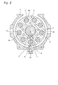
Fig. 2 is a sectional view of the motor orthogonal to an axis of a drive shaft. -
Fig. 3 is a circuit diagram of the motor. -
Fig. 4 is a sectional view of a flushing valve. -
Fig. 5 is a sectional view illustrating a motor of another embodiment. -
Fig. 6 is a sectional view illustrating a conventional axial piston motor. - Hereinafter, this invention will be described in detail by way of embodiments thereof illustrated in the accompanying drawings.
-
Fig. 1 is sectional view illustrating an axial piston motor of one embodiment of this invention. As illustrated inFig. 1 , this motor includes ahousing 1, adrive shaft 3 mounted to thishousing 1 through abearing 2 so as to be freely rotatable, and acylinder block 4 fixed to thisdrive shaft 3. - The
cylinder block 4 has a plurality ofcylinders 40 arrayed in a circumferential direction. A plurality ofpistons 5 is fitted into this plurality ofcylinders 40 so as to be capable of freely advancing and retreating. - A tip part of the
piston 5 is formed in a spherical shape and coupled to ashoe 6. Thisshoe 6 is supported by aswash plate 7 positioned relatively to thehousing 1. Thisswash plate 7 has a tiltable surface relative to thedrive shaft 3, and supports the plurality ofpistons 5 by the tilted surface. A tilting angle of thisswash plate 7 relative to thedrive shaft 3 is adjusted by afirst control piston 81 and asecond control piston 82. - The
housing 1 has acover 10 covering an end part side of thedrive shaft 3. A firstmain passage 11 and a secondmain passage 12, which are connected to thecylinder 40 and supply and discharge operation oil to thecylinder 40, are provided at thiscover 10. - A
valve plate 9 is mounted on an end surface of thecover 10 on thecylinder block 4 side. Thisvalve plate 9 has an arc-shapedfirst port 91 and an arc-shapedsecond port 92, and thefirst port 91 and thesecond port 92 are formed symmetrically. - A
port 40a for supplying and discharging the operation oil to an inside of thecylinder 40 is formed at a bottom part of eachcylinder 40. An end surface of thecylinder block 4 is in contact with thevalve plate 9. - The first
main passage 11 of thecover 10, thefirst port 91 of thevalve plate 9, and theport 40a of thepredetermined cylinder 40 communicate with one another. The secondmain passage 12 of thecover 10, thesecond port 92 of thevalve plate 9, and theport 40a of thepredetermined cylinder 40 communicate with one another. - Then, when the operation oil is supplied from the first
main passage 11, the operation oil flows into thepredetermined cylinder 40 via thefirst port 91. As a result, thepiston 5 reciprocates, and in this moving ofpiston 5 reciprocally, thecylinder block 4 and thedrive shaft 3 are rotated in one direction. After that, the operation oil within thecylinder 40 is discharged from the secondmain passage 12 via thesecond port 92. A pressure within the firstmain passage 11 on a supply side is higher than a pressure within the secondmain passage 12 on a discharge side. - On the other hand, when the operation oil is supplied from the second
main passage 12, thecylinder block 4 and thedrive shaft 3 are rotated in another direction. After that, the operation oil within thecylinder 40 is discharged from the firstmain passage 11. - A
nozzle 21 for jetting the operation oil is arranged on an inner surface of thehousing 1 and is provided at a position opposite to an outer circumferential surface of thecylinder block 4. Thisnozzle 21 is provided at a tip part of aplug 20. Thisplug 20 is screwed to thehousing 1 in a penetrated state. - The
nozzle 21 faces anozzle passage 15 provided at thehousing 1, and thenozzle passage 15 is connected to a flushingvalve 30 provided at thecover 10 of thehousing 1. This flushingvalve 30 is connected to a first sub-passage 13 communicated with the firstmain passage 11 and is connected to a second sub-passage 14 communicated with the secondmain passage 12. This flushingvalve 30 is switched by pressure difference between the firstmain passage 11 and the secondmain passage 12, and the operation oil passing through the main passage on a low pressure side is guided to thenozzle 21 via thenozzle passage 15. - As illustrated in
Figs. 1 and2 , an outer circumferential surface of thecylinder block 4 has a high temperature zone Z where a temperature can be higher than a predetermined threshold value during rotation of thecylinder block 4. The threshold value is a value in which seizure of at least one of thepiston 5 and thecylinder 40 can occur between during the rotation of thecylinder block 4. - As viewed in an axial direction of the
drive shaft 3, the high temperature zone Z of thecylinder block 4 is in a set range R where a center angle is from +40° to -40° when a position L, at which thepiston 5 is at a bottom dead center, is selected as a standard. Here, a positive direction of the center angle is a rotation direction of thecylinder block 4. The bottom dead center of thepiston 5 is a position where thepiston 5 is protruded the most from thecylinder 40. - Most specifically, a line connecting a center of the
piston 5 and a center of thedrive shaft 3, which represents the bottom dead center, is selected as a standard line B, the set range R is a range where the center angle is from +40° to -40° around the standard line B. - The
nozzle 21 is opposed to the high temperature zone Z of thecylinder block 4. Specifically speaking, as viewed in the axial direction of thedrive shaft 3, thenozzle 21 is disposed outside the position L at which thepiston 5 is at the bottom dead center in a radial direction. As viewed in the axial direction of thedrive shaft 3, a jetting direction of thenozzle 21 intersects the set range R of thecylinder block 4. As viewed in the axial direction of thedrive shaft 3, the jetting direction of thenozzle 21 coincides with a radial direction of the cylinder block 4 (the standard line B). -
Fig. 3 illustrates a circuit diagram of the motor. As illustrated inFig. 3 , the firstmain passage 11 and the secondmain passage 12 are connected to amotor unit 50 including thedrive shaft 3, thecylinder block 4, thepiston 5, and theswash plate 7. The first sub-passage 13 branched from the firstmain passage 11 is connected to a first port P1 of aspool 31 of the flushingvalve 30, and the second sub-passage 14 branched from the secondmain passage 12 is connected to a second port P2 of thespool 31. Thenozzle passage 15 faced by thenozzle 21 is connected to a third port P3 of thespool 31. - The
spool 31 can be situated at a first position S1, a second position S2, and a third position S3. The first position S1 is a neutral position, and the first port P1 and the second port P2 are not connected to the third port P3 in the neutral position. At the second position S2, the second port P2 is connected to the third port P3. At the third position S3, the first port P1 is connected to the third port P3. - Then, in a case where high pressure operation oil is supplied to the first
main passage 11 and low pressure operation oil is discharged from the secondmain passage 12, thespool 31 is switched from the first position S1 to the second position S2 by a differential pressure between the high pressure operation oil in thefirst sub-passage 13 and the low pressure operation oil in thesecond sub-passage 14, and thesecond sub-passage 14 communicates with thenozzle passage 15. With this configuration, the low pressure operation oil in the second sub-passage 14 can be jetted from thenozzle 21 to themotor unit 50. - On the other hand, in a case where high pressure operation oil is supplied to the second
main passage 12 and low pressure operation oil is discharged from the firstmain passage 11, thespool 31 is switched from the first position S1 to the third position S3 by a differential pressure between the high pressure operation oil in thesecond sub-passage 14 and the low pressure operation oil in the first sub-passage 13, and thefirst sub-passage 13 communicates with thenozzle passage 15. With this configuration, the low pressure operation oil in the first sub-passage 13 can be jetted from thenozzle 21 to themotor unit 50. - The first and
second control pistons 81, 82 (illustrated inFig. 1 ) may be driven by branching passages from thefirst sub-passage 13 and thesecond sub-passage 14 and flowing the operation oil into thesepistons -
Fig. 4 is a sectional view of the flushingvalve 30. As illustrated inFig. 4 , thespool 31 is fitted into avalve hole 32 provided at thecover 10 of thehousing 1 so as to be freely slidable. Then, as illustrated by a solid arrow, when the high pressure operation oil is supplied to the first sub-passage 13, thespool 31 receives this high pressure operation oil and is moved to a right side in the drawing (the second position S2 inFig. 3 ). As illustrated in dotted arrows, the low pressure operation oil is supplied from the second sub-passage 14 to thenozzle passage 15. - In the above-structured
axial piston 5 motor, on the inner surface of thehousing 1, thenozzle 21 for jetting operation oil is provided at the position opposite to the outer circumferential surface of thecylinder block 4. With this configuration, by spraying the operation oil from thenozzle 21 to the outer circumferential surface of thecylinder block 4 during the rotation of thecylinder block 4, this operation oil can remove frictional heat generated by the sliding between thepiston 5 and thecylinder 40, and seizure of thepiston 5 and seizure of thecylinder 40 can be prevented. - Therefore, since the seizure of the
piston 5 and the seizure of thecylinder 40 can be prevented, thecylinder block 4 can be operated at high speed rotation. Further, since the seizure of thepiston 5 and the seizure of thecylinder 40 can be prevented without increasing a clearance between thepiston 5 and thecylinder 40, deterioration of performance due to an increase in an amount of the operation oil leaked from thecylinder 40 can be prevented. - Further, since the
nozzle 21 is opposed to the high temperature zone Z of thecylinder block 4, the operation oil can be sprayed from thenozzle 21 to the high temperature zone Z, and the seizure of thepiston 5 and the seizure of thecylinder 40 can be reliably prevented. - Further, though the high temperature zone Z becomes a zone where seizure can occur the most, the high temperature zone Z is in the set range R. Accordingly, the seizure can be reliably prevented by the jetting of the operation oil from the
nozzle 21. - Further, the
nozzle 21 is disposed outside in the radial direction of the position L at which thepiston 5 is at the bottom dead center, and the jetting direction of thenozzle 21 intersects the set range R of thecylinder block 4. Accordingly, thenozzle 21 is disposed at the appropriate position. - Further, the
plug 20 is screwed to thehousing 1, and theplug 20 has thenozzle 21. Accordingly, the attachment and removal of thenozzle 21 to and from thehousing 1 can be easily performed by attaching and removing theplug 20 to and from thehousing 1. - Further, since the flushing
valve 30 is provided at thehousing 1, the motor can be made compact. - It should be noted that this invention is not limited to the aforementioned embodiment. The numbers of the
piston 5 and thecylinder 40 may be increased and decreased. The number of thenozzle 21 may be increased and decreased. - Further, in the above-described embodiment, the set range R of the
cylinder block 4 is a range where the center angle is from +40° to -40° around the standard line B. However, the set range R may be a range where the center angle is from +15° to -15° around the standard line B. With this configuration, the operation oil can be sprayed at pinpoint from thenozzle 21 to an area of thecylinder block 4 where it is highly possible that the seizure occurs. - Further, in the above-described embodiment, as viewed in the axial direction of the
drive shaft 3, the jetting direction of thenozzle 21 coincides with the radial direction of thecylinder block 4. However, as long as the jetting direction of thenozzle 21 intersects the set range R, the jetting direction may be tilted in the radial direction of thecylinder block 4. Needless to say, a specific numerical value of the set range R is not limited to this embodiment, and designs can be modified. - Further, in the above-described embodiment, on the plane surface including the
nozzle 21 and the axis of thedrive shaft 3, the jetting direction of thenozzle 21 coincides with the direction (the radial direction) orthogonal to the axis of thedrive shaft 3. However, as illustrated inFig. 5 , a jetting direction of anozzle 21 may be tilted in a range θ of from +45° to -45° when a direction S orthogonal to an axis of adrive shaft 3 is selected as a standard. - Further, in the above-described embodiment, the
nozzle 21 is a part of theplug 20. However, thenozzle 21 may be directly formed at thehousing 1. - In the above-described embodiment, the nozzle may be opposed to a zone other than the high temperature zone. The high temperature zone may be a range other than the range where the center angle is from +40° to -40°. The nozzle may be disposed outside a position other than the position where the piston is at the bottom dead center in the radial direction. The nozzle may be provided at a part other than the plug. The flushing valve may be omitted.
-
- 1:
- Housing
- 3:
- Drive shaft
- 4:
- Cylinder block
- 5:
- Piston
- 7:
- Swash plate
- 9:
- Valve plate
- 10:
- Cover
- 11:
- First main passage
- 12:
- Second main passage
- 13:
- First sub-passage
- 14:
- Second sub-passage
- 15:
- Nozzle passage
- 20:
- Plug
- 21:
- Nozzle
- 30:
- Flushing valve
- 31:
- Spool
- 40:
- Cylinder
- 40a:
- Port
- B:
- Standard line
- L:
- Position where piston is at bottom dead center
- R:
- Set range
- Z:
- High temperature zone
Claims (6)
- An axial piston motor comprising:a housing;a drive shaft which is mounted to the housing so as to be freely rotatable;a cylinder block which is fixed to the drive shaft and has a plurality of cylinders arrayed in a circumferential direction;a plurality of pistons which is fitted into the plurality of cylinders so as to be capable of freely advancing and retreating; anda swash plate which supports the plurality of pistons by a tiltable surface relative to the drive shaft, whereinon an inner surface of the housing, a nozzle for jetting operation oil is provided at a position opposite to an outer circumferential surface of the cylinder block.
- The axial piston motor according to claim 1, wherein
the outer circumferential surface of the cylinder block has a high temperature zone which has a temperature higher than a predetermined threshold value during rotation of the cylinder block, and
the nozzle is opposed to the high temperature zone of the cylinder block. - The axial piston motor according to claim 2, wherein
as viewed in an axial direction of the drive shaft, the high temperature zone of the cylinder block is in a set range where a center angle is from +40° to -40° when a bottom dead center of the piston is selected as a standard. - The axial piston motor according to claim 3, wherein
as viewed in the axial direction of the drive shaft, the nozzle is disposed outside the position at which the piston is at the bottom dead center in a radial direction, and
as viewed in the axial direction of the drive shaft, a jetting direction of the nozzle intersects the set range of the cylinder block. - The axial piston motor according to any one of claims 1 to 4, further comprising
a plug screwed to the housing in a penetrated state, wherein
the plug has the nozzle. - The axial piston motor according to any one of claims 1 to 5, wherein
the housing has a pair of main passages, which is connected to the cylinder and supplies and discharges the operation oil to the cylinder and
a flushing valve, which is switched by pressure difference between the pair of main passages and guides the operation oil passing through the main passage on a low pressure side to the nozzle, is provided at the housing.
Applications Claiming Priority (2)
| Application Number | Priority Date | Filing Date | Title |
|---|---|---|---|
| JP2012285032A JP2014126020A (en) | 2012-12-27 | 2012-12-27 | Axial piston motor |
| PCT/JP2013/081730 WO2014103590A1 (en) | 2012-12-27 | 2013-11-26 | Axial piston motor |
Publications (1)
| Publication Number | Publication Date |
|---|---|
| EP2940291A1 true EP2940291A1 (en) | 2015-11-04 |
Family
ID=51020684
Family Applications (1)
| Application Number | Title | Priority Date | Filing Date |
|---|---|---|---|
| EP13868490.7A Withdrawn EP2940291A1 (en) | 2012-12-27 | 2013-11-26 | Axial piston motor |
Country Status (7)
| Country | Link |
|---|---|
| US (1) | US20150000513A1 (en) |
| EP (1) | EP2940291A1 (en) |
| JP (1) | JP2014126020A (en) |
| KR (1) | KR20140126769A (en) |
| CN (1) | CN104379923A (en) |
| IN (1) | IN2014DN07165A (en) |
| WO (1) | WO2014103590A1 (en) |
Families Citing this family (4)
| Publication number | Priority date | Publication date | Assignee | Title |
|---|---|---|---|---|
| JP6206513B2 (en) * | 2016-01-14 | 2017-10-04 | 株式会社豊田自動織機 | Variable displacement swash plate type piston pump |
| JP6984825B2 (en) | 2017-01-13 | 2021-12-22 | 学校法人 関西大学 | Method for producing an organosilicon compound by hydrosilylation using nanoparticles containing a metal element |
| JP7476060B2 (en) * | 2020-09-14 | 2024-04-30 | 株式会社小松製作所 | Valve plates, cylinder blocks, hydraulic motors |
| US11994117B2 (en) * | 2021-10-04 | 2024-05-28 | Hamilton Sundstrand Corporation | Variable positive displacement pump actuator systems |
Family Cites Families (14)
| Publication number | Priority date | Publication date | Assignee | Title |
|---|---|---|---|---|
| JPS5521187B2 (en) * | 1972-03-29 | 1980-06-07 | ||
| JPS5521187A (en) * | 1978-08-03 | 1980-02-15 | Mitsubishi Electric Corp | Semiconductor device |
| JPS5549162A (en) * | 1978-10-03 | 1980-04-09 | Ikeuchi:Kk | Mist producting device |
| JP3932659B2 (en) * | 1998-03-30 | 2007-06-20 | 株式会社豊田自動織機 | Refrigerant suction structure in compressor |
| JP2000246153A (en) * | 1999-03-03 | 2000-09-12 | Kuroda Precision Ind Ltd | Liquid atomizer |
| JP4577969B2 (en) * | 2000-09-26 | 2010-11-10 | 三輪精機株式会社 | Hydraulic motor |
| JP2002242824A (en) * | 2001-02-14 | 2002-08-28 | Sauer-Danfoss-Daikin Ltd | Hydraulic piston pump and hydrostatic transmission using the same |
| JP4050899B2 (en) * | 2001-12-21 | 2008-02-20 | ユニクラ インターナショナル リミテッド | Swash plate compressor and its housing |
| FR2891863B1 (en) * | 2005-10-11 | 2010-10-08 | Inst Francais Du Petrole | PROCESS FOR REMOVING FUEL FROM LUBRICATING OIL OF INTERNAL COMBUSTION ENGINE AND ENGINE USING SUCH A METHOD |
| JP4828371B2 (en) | 2006-10-23 | 2011-11-30 | ボッシュ・レックスロス株式会社 | Axial piston pump / motor |
| DE102009056518A1 (en) * | 2009-12-02 | 2011-06-09 | Bock Kältemaschinen GmbH | compressor |
| JP5444088B2 (en) * | 2010-03-31 | 2014-03-19 | 川崎重工業株式会社 | Valve plate and axial piston type hydraulic pump / motor equipped with the same |
| US8500418B2 (en) * | 2010-10-28 | 2013-08-06 | Spx Corporation | Internally supplied air jet cooling for a hydraulic pump |
| KR101330768B1 (en) * | 2010-11-16 | 2013-11-18 | 카와사키 주코교 카부시키 카이샤 | Cooling structure of cylinder block and swash plate type liquid-pressure apparatus including same |
-
2012
- 2012-12-27 JP JP2012285032A patent/JP2014126020A/en active Pending
-
2013
- 2013-11-26 KR KR1020147027049A patent/KR20140126769A/en not_active Ceased
- 2013-11-26 CN CN201380033130.9A patent/CN104379923A/en active Pending
- 2013-11-26 IN IN7165DEN2014 patent/IN2014DN07165A/en unknown
- 2013-11-26 EP EP13868490.7A patent/EP2940291A1/en not_active Withdrawn
- 2013-11-26 WO PCT/JP2013/081730 patent/WO2014103590A1/en not_active Ceased
- 2013-11-26 US US14/378,421 patent/US20150000513A1/en not_active Abandoned
Non-Patent Citations (1)
| Title |
|---|
| See references of WO2014103590A1 * |
Also Published As
| Publication number | Publication date |
|---|---|
| CN104379923A (en) | 2015-02-25 |
| KR20140126769A (en) | 2014-10-31 |
| WO2014103590A1 (en) | 2014-07-03 |
| IN2014DN07165A (en) | 2015-04-24 |
| JP2014126020A (en) | 2014-07-07 |
| US20150000513A1 (en) | 2015-01-01 |
Similar Documents
| Publication | Publication Date | Title |
|---|---|---|
| KR101390584B1 (en) | Valve plate, and axial piston hydraulic pump and axial piston hydraulic motor with same | |
| US20130000481A1 (en) | Cooling structure of cylinder block and swash plate type liquid-pressure apparatus including same | |
| JP3570517B2 (en) | Axial piston machine with cooling circuit for cylinder and piston | |
| WO2016006465A1 (en) | Hydraulic rotary machine | |
| US20150000513A1 (en) | Axial piston motor | |
| EP3115604A1 (en) | Piston pump and valve plate for piston pump | |
| EP2988003A1 (en) | Piston for axial piston pump motor, cylinder block for axial piston pump motor, and axial piston pump motor | |
| WO2024154671A1 (en) | Rotating cylinder | |
| KR102345509B1 (en) | Cylinder block and swash plate hydraulic rotation device having the same | |
| US20040247454A1 (en) | Hydrostatic machine with compensated sleeves | |
| EP2778410B1 (en) | Hydraulic rotary machine | |
| JP4577969B2 (en) | Hydraulic motor | |
| JP6913260B2 (en) | Cylinder block and swash plate hydraulic rotary device equipped with it | |
| CN221482081U (en) | Hydraulic rotary machine, cylinder block of hydraulic rotary machine, and valve plate of hydraulic rotary machine | |
| KR102861444B1 (en) | Hydraulic pump and construction machine | |
| US20150377209A1 (en) | Hydraulic rotary apparatus | |
| WO2026083970A1 (en) | Rotary cylinder and method for using same | |
| KR19990003274U (en) | Water pump housing of car | |
| KR20120126027A (en) | Hydraulic motor, hydraulic motor apparatus, and construction machine mounting hydraulic motor apparatus |
Legal Events
| Date | Code | Title | Description |
|---|---|---|---|
| PUAI | Public reference made under article 153(3) epc to a published international application that has entered the european phase |
Free format text: ORIGINAL CODE: 0009012 |
|
| 17P | Request for examination filed |
Effective date: 20141224 |
|
| AK | Designated contracting states |
Kind code of ref document: A1 Designated state(s): AL AT BE BG CH CY CZ DE DK EE ES FI FR GB GR HR HU IE IS IT LI LT LU LV MC MK MT NL NO PL PT RO RS SE SI SK SM TR |
|
| AX | Request for extension of the european patent |
Extension state: BA ME |
|
| STAA | Information on the status of an ep patent application or granted ep patent |
Free format text: STATUS: THE APPLICATION HAS BEEN WITHDRAWN |
|
| 18W | Application withdrawn |
Effective date: 20151218 |