EP2940268A1 - Engine intake port structure - Google Patents
Engine intake port structure Download PDFInfo
- Publication number
- EP2940268A1 EP2940268A1 EP13866707.6A EP13866707A EP2940268A1 EP 2940268 A1 EP2940268 A1 EP 2940268A1 EP 13866707 A EP13866707 A EP 13866707A EP 2940268 A1 EP2940268 A1 EP 2940268A1
- Authority
- EP
- European Patent Office
- Prior art keywords
- intake port
- intake
- chamfer
- combustion chamber
- port
- Prior art date
- Legal status (The legal status is an assumption and is not a legal conclusion. Google has not performed a legal analysis and makes no representation as to the accuracy of the status listed.)
- Granted
Links
Images




Classifications
-
- F—MECHANICAL ENGINEERING; LIGHTING; HEATING; WEAPONS; BLASTING
- F02—COMBUSTION ENGINES; HOT-GAS OR COMBUSTION-PRODUCT ENGINE PLANTS
- F02B—INTERNAL-COMBUSTION PISTON ENGINES; COMBUSTION ENGINES IN GENERAL
- F02B31/00—Modifying induction systems for imparting a rotation to the charge in the cylinder
-
- F—MECHANICAL ENGINEERING; LIGHTING; HEATING; WEAPONS; BLASTING
- F01—MACHINES OR ENGINES IN GENERAL; ENGINE PLANTS IN GENERAL; STEAM ENGINES
- F01L—CYCLICALLY OPERATING VALVES FOR MACHINES OR ENGINES
- F01L1/00—Valve-gear or valve arrangements, e.g. lift-valve gear
- F01L1/26—Valve-gear or valve arrangements, e.g. lift-valve gear characterised by the provision of two or more valves operated simultaneously by same transmitting-gear; peculiar to machines or engines with more than two lift-valves per cylinder
- F01L1/265—Valve-gear or valve arrangements, e.g. lift-valve gear characterised by the provision of two or more valves operated simultaneously by same transmitting-gear; peculiar to machines or engines with more than two lift-valves per cylinder peculiar to machines or engines with three or more intake valves per cylinder
-
- F—MECHANICAL ENGINEERING; LIGHTING; HEATING; WEAPONS; BLASTING
- F02—COMBUSTION ENGINES; HOT-GAS OR COMBUSTION-PRODUCT ENGINE PLANTS
- F02B—INTERNAL-COMBUSTION PISTON ENGINES; COMBUSTION ENGINES IN GENERAL
- F02B31/00—Modifying induction systems for imparting a rotation to the charge in the cylinder
- F02B31/04—Modifying induction systems for imparting a rotation to the charge in the cylinder by means within the induction channel, e.g. deflectors
- F02B31/042—Modifying induction systems for imparting a rotation to the charge in the cylinder by means within the induction channel, e.g. deflectors induction channel having a helical shape around the intake valve axis
-
- F—MECHANICAL ENGINEERING; LIGHTING; HEATING; WEAPONS; BLASTING
- F02—COMBUSTION ENGINES; HOT-GAS OR COMBUSTION-PRODUCT ENGINE PLANTS
- F02B—INTERNAL-COMBUSTION PISTON ENGINES; COMBUSTION ENGINES IN GENERAL
- F02B31/00—Modifying induction systems for imparting a rotation to the charge in the cylinder
- F02B31/08—Modifying induction systems for imparting a rotation to the charge in the cylinder having multiple air inlets
- F02B31/085—Modifying induction systems for imparting a rotation to the charge in the cylinder having multiple air inlets having two inlet valves
-
- F—MECHANICAL ENGINEERING; LIGHTING; HEATING; WEAPONS; BLASTING
- F02—COMBUSTION ENGINES; HOT-GAS OR COMBUSTION-PRODUCT ENGINE PLANTS
- F02F—CYLINDERS, PISTONS OR CASINGS, FOR COMBUSTION ENGINES; ARRANGEMENTS OF SEALINGS IN COMBUSTION ENGINES
- F02F1/00—Cylinders; Cylinder heads
- F02F1/24—Cylinder heads
- F02F1/42—Shape or arrangement of intake or exhaust channels in cylinder heads
-
- F—MECHANICAL ENGINEERING; LIGHTING; HEATING; WEAPONS; BLASTING
- F02—COMBUSTION ENGINES; HOT-GAS OR COMBUSTION-PRODUCT ENGINE PLANTS
- F02F—CYLINDERS, PISTONS OR CASINGS, FOR COMBUSTION ENGINES; ARRANGEMENTS OF SEALINGS IN COMBUSTION ENGINES
- F02F1/00—Cylinders; Cylinder heads
- F02F1/24—Cylinder heads
- F02F1/42—Shape or arrangement of intake or exhaust channels in cylinder heads
- F02F1/4228—Helically-shaped channels
-
- F—MECHANICAL ENGINEERING; LIGHTING; HEATING; WEAPONS; BLASTING
- F02—COMBUSTION ENGINES; HOT-GAS OR COMBUSTION-PRODUCT ENGINE PLANTS
- F02F—CYLINDERS, PISTONS OR CASINGS, FOR COMBUSTION ENGINES; ARRANGEMENTS OF SEALINGS IN COMBUSTION ENGINES
- F02F1/00—Cylinders; Cylinder heads
- F02F1/24—Cylinder heads
- F02F1/42—Shape or arrangement of intake or exhaust channels in cylinder heads
- F02F1/4235—Shape or arrangement of intake or exhaust channels in cylinder heads of intake channels
-
- F—MECHANICAL ENGINEERING; LIGHTING; HEATING; WEAPONS; BLASTING
- F02—COMBUSTION ENGINES; HOT-GAS OR COMBUSTION-PRODUCT ENGINE PLANTS
- F02M—SUPPLYING COMBUSTION ENGINES IN GENERAL WITH COMBUSTIBLE MIXTURES OR CONSTITUENTS THEREOF
- F02M35/00—Combustion-air cleaners, air intakes, intake silencers, or induction systems specially adapted for, or arranged on, internal-combustion engines
- F02M35/10—Air intakes; Induction systems
-
- F—MECHANICAL ENGINEERING; LIGHTING; HEATING; WEAPONS; BLASTING
- F02—COMBUSTION ENGINES; HOT-GAS OR COMBUSTION-PRODUCT ENGINE PLANTS
- F02M—SUPPLYING COMBUSTION ENGINES IN GENERAL WITH COMBUSTIBLE MIXTURES OR CONSTITUENTS THEREOF
- F02M35/00—Combustion-air cleaners, air intakes, intake silencers, or induction systems specially adapted for, or arranged on, internal-combustion engines
- F02M35/10—Air intakes; Induction systems
- F02M35/104—Intake manifolds
- F02M35/108—Intake manifolds with primary and secondary intake passages
- F02M35/1085—Intake manifolds with primary and secondary intake passages the combustion chamber having multiple intake valves
-
- F—MECHANICAL ENGINEERING; LIGHTING; HEATING; WEAPONS; BLASTING
- F01—MACHINES OR ENGINES IN GENERAL; ENGINE PLANTS IN GENERAL; STEAM ENGINES
- F01L—CYCLICALLY OPERATING VALVES FOR MACHINES OR ENGINES
- F01L3/00—Lift-valve, i.e. cut-off apparatus with closure members having at least a component of their opening and closing motion perpendicular to the closing faces; Parts or accessories thereof
-
- F—MECHANICAL ENGINEERING; LIGHTING; HEATING; WEAPONS; BLASTING
- F01—MACHINES OR ENGINES IN GENERAL; ENGINE PLANTS IN GENERAL; STEAM ENGINES
- F01L—CYCLICALLY OPERATING VALVES FOR MACHINES OR ENGINES
- F01L3/00—Lift-valve, i.e. cut-off apparatus with closure members having at least a component of their opening and closing motion perpendicular to the closing faces; Parts or accessories thereof
- F01L3/06—Valve members or valve-seats with means for guiding or deflecting the medium controlled thereby, e.g. producing a rotary motion of the drawn-in cylinder charge
-
- F—MECHANICAL ENGINEERING; LIGHTING; HEATING; WEAPONS; BLASTING
- F02—COMBUSTION ENGINES; HOT-GAS OR COMBUSTION-PRODUCT ENGINE PLANTS
- F02M—SUPPLYING COMBUSTION ENGINES IN GENERAL WITH COMBUSTIBLE MIXTURES OR CONSTITUENTS THEREOF
- F02M35/00—Combustion-air cleaners, air intakes, intake silencers, or induction systems specially adapted for, or arranged on, internal-combustion engines
- F02M35/10—Air intakes; Induction systems
- F02M35/104—Intake manifolds
- F02M35/112—Intake manifolds for engines with cylinders all in one line
-
- Y—GENERAL TAGGING OF NEW TECHNOLOGICAL DEVELOPMENTS; GENERAL TAGGING OF CROSS-SECTIONAL TECHNOLOGIES SPANNING OVER SEVERAL SECTIONS OF THE IPC; TECHNICAL SUBJECTS COVERED BY FORMER USPC CROSS-REFERENCE ART COLLECTIONS [XRACs] AND DIGESTS
- Y02—TECHNOLOGIES OR APPLICATIONS FOR MITIGATION OR ADAPTATION AGAINST CLIMATE CHANGE
- Y02T—CLIMATE CHANGE MITIGATION TECHNOLOGIES RELATED TO TRANSPORTATION
- Y02T10/00—Road transport of goods or passengers
- Y02T10/10—Internal combustion engine [ICE] based vehicles
- Y02T10/12—Improving ICE efficiencies
Definitions
- the present disclosure relates to an engine intake port structure, and more particularly, to an engine intake port structure that weakens a swirl flow of intake air during an intake stroke so as to extend a waiting time in a combustion chamber.
- an engine includes a cylinder block and a cylinder head block.
- a cylinder is formed, and in the cylinder head block, an intake port and an exhaust port are formed.
- an injector and a glow plug are provided in the cylinder head block. That is, air is introduced into a combustion chamber through the intake port and fuel is injected by the injector, so that the air and the fuel are mixed to form a mixed gas, and the mixed gas is exploded and burned by a compression stroke of a piston. After being burned, the mixed gas is discharged as an exhaust gas through the exhaust port.
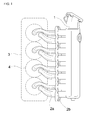
- FIG. 1 is a diagram provided to explain a conventional engine intake port structure.
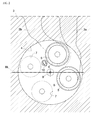
- FIG. 2 is a bottom view of a cylinder head block provided to explain the conventional engine intake port structure.
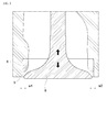
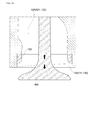
- FIG. 3 is a longitudinal cross-sectional view of an intake port provided to explain the conventional engine intake port structure.
- an intake manifold 1 is provided on one side of a cylinder head block 3.
- the intake manifold 1 is configured to suck fresh air from the outside or to be supplied with intake air by a turbocharger.
- the intake manifold 1 and a combustion chamber 4 are connected to each other by first and second intake ports 2a and 2b.
- first and second intake ports 2a and 2b To be more specific, in the cylinder head block 3, an intake port 5 and an exhaust port 7 are formed, and the intake port 5 and the exhaust port 7 are disposed within the combustion chamber 4.
- the intake port 5 is connected to the above-described first and second intake ports 2a and 2b, and a valve unit 8 is installed. That is, if the valve unit 8 is opened at the intake port 5, fresh air is supplied into the combustion chamber, and if the valve unit 8 closes the intake port 5, the combustion chamber is sealed.
- valve sheet 6 is provided at the intake port 5.
- the valve sheet 6 is brought into close contact with the valve unit 8 so as to maintain a sealed state of the combustion chamber.
- an exhaust port 7 is configured to exhaust the gas.
- the exhaust port 7 is provided with an exhaust valve for opening/closing the exhaust port 7.
- an injector 9 is installed at a central portion of the combustion chamber 4.
- the injector 9 is configured to inject fuel to the combustion chamber.
- a glow plug 10 may be installed so as to be close to the injector 9.
- the glow plug 10 is used to warm up fuel.
- intake air may be supplied to the intake manifold 1.
- Such compressed air may have a swirl depending on a shape of a flow path while passing through the first and second intake ports 2a and 2b. The swirl enables the intake air and fuel to be mixed well in the combustion chamber.
- a corner at an end of the intake port 5 may be formed in a linear fashion without a particular shape, or even if a chamber is formed, the chamber is provided in a concentric manner with an inner diameter of the intake port 5.
- opening widths w1 and w2 are equal to each other at four sides of the valve unit 8 regardless of a position of a level of the valve unit 8.
- the opening widths w1 and w2 are narrow, and thus, the intake air is introduced into the combustion chamber at a high pressure while the swirls are formed in the intake air.
- the intake air introduced as such flows and is mixed with fuel.
- a glow plug 10 may be provided in the combustion chamber 4. That is, the intake air may be supplied toward a space where the glow plug 10 is disposed. Thus, the intake air may cause interference with the glow plug 10 and the swirl may be randomly scattered, so that the intake air and the fuel may not be mixed well.
- a vortex flow i.e., a swirl flow
- the air and fuel can be smoothly mixed and smoke can be reduced.
- the first and second intake ports 2a and 2b As components for generating a swirl, there are the first and second intake ports 2a and 2b.
- the first intake port 2a may be provided as a helical port, so that a swirl is generated while the intake air passes through the first intake port 2a.
- the second intake port 2b is disposed such that the intake air can be introduced in a tangential direction from an edge of the combustion chamber, and, thus, the intake air forms a swirl itself while passing through the second intake port 2b.
- a swirl (vortex) flow ratio is proportional to an opening width of an intake valve. That is, if the opening width of the intake valve is small, the swirl flow ratio is low, whereas if the opening width of the intake valve is large, the swirl flow ratio is high.
- the swirl flow ratio increases as the opening width of the intake valve increases in the middle of an intake stroke.
- an air volume decreases and a swirl of air sucked through an intake port becomes gradually smaller.
- the length of time during which air remains in a combustion chamber is short due to a swirl flow, there may be a problem of incomplete combustion.
- An embodiment of the present disclosure is suggested to solve the above-described problem.
- An object of the present disclosure is to provide an engine intake port structure in which a chamfer is formed to be offset to an end corner of an intake port, and, thus, a swirl flow of intake air is weakened at the end of an intake stroke so as to allow the air to remain in a combustion chamber for a long time.
- An engine intake port structure in order to achieve the above-described technical object includes: a cylinder head block 100 including an intake port 110 and an exhaust port 140; an injector 182 installed at a central portion of a combustion chamber 170 in the cylinder head block 100 and configured to inject fuel; and a valve unit 160 installed in the cylinder head block 100 and configured to open and close the intake port 110, wherein at an end corner of the intake port 110, a chamfer 130 is formed to be offset (a) with respect to the center of the intake port 110, and when the intake port 110 is opened/closed by the valve unit 160, introduction of intake air is concentrated on a side in which an opening width of the chamfer 130 is wide at the beginning of an opening stage, and after the intake port 110 is opened, opening widths are formed to be similar at four sides of the valve unit 160, so that a swirl formed in the intake air is weakened.
- the intake port 110 may be provided in multiple as first and second intake ports 111 and 112, and at an end corner of the first intake port 111, a first chamfer 131 may be formed to be offset (a) with respect to the center of the first intake port 111 and at an end corner of the second intake port 112, a second chamfer 132 may be formed to be offset (a) with respect to the center of the second intake port 112.
- offset directions D and D1 of the first chamfer 131 may be opposite to offset directions D and D2 of the second chamfer 132 by 180 degrees.
- the offset directions D of the first and second chamfers 131 and 132 may have torsion angles b1 and b2, respectively, with respect to the base line BL.
- the intake port 110 may be provided in multiple as first and second intake ports 111 and 112, and the first intake port 111 may be connected to a first intake port 121 and the second intake port 112 may be connected to a second intake port 122, and the first intake port 121 may be a helical port formed in a helical direction with respect to the combustion chamber 170 and the second intake port 122 may be a tangential port formed in a tangential direction with respect to the combustion chamber 170.
- a diesel engine intake port structure which is formed to have torsion to control a swirl flow of a mixed gas includes: a cylinder head block 100 including a first intake port 111 and a second intake port 112 adjacent to the first intake port 111; first and second intake ports 121 and 122 connected to the intake ports and configured to suck air; valve sheet units 160 provided in the cylinder head block 100 and installed between the first and second intake ports 121 and 122 and the first and second intake ports 111 and 112; and chamfers 130 which are formed such that an inclination angle toward a combustion chamber from the environs of the first and second intake ports 111 and 112 is changed, wherein an inclination direction of the chamfer 130 formed at the first intake port 111 is opposite to an inclination direction of the chamfer 130 formed at the adjacent second intake port 112.
- the first and second intake ports 121 and 122 may include a helical port installed in a helical shape in the cylinder head block 100 and a tangential port arranged in a tangential direction at an edge of the combustion chamber.
- the inclination direction of the chamfer 130 formed at the first intake port 111 may be twisted by 30 degrees in an anticlockwise direction based on a longitudinal direction of the cylinder head block 100 and the inclination direction of the chamfer 130 formed at the second intake port 112 may be twisted by 210 degrees in the anticlockwise direction based on the longitudinal direction of the cylinder head block 100.
- a first effect of the present disclosure is that a swirl flow of intake air can be weakened by a simple structure.
- a second effect of the present disclosure is that efficiency of an engine can be improved and contaminants in an exhaust gas can be reduced by increasing mixability between fuel and air.
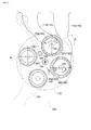
- FIG. 4 and FIG. 5 are bottom views of a cylinder head block provided to explain an engine intake port structure according to an exemplary embodiment of the present disclosure.
- FIG. 6 is a diagram provided to explain an intake port formed at a cylinder head block in an engine intake port structure according to an exemplary embodiment of the present disclosure.
- FIG. 7 is a diagram provided to explain a chamfer formed at an intake port in an engine intake port structure according to an exemplary embodiment of the present disclosure.
- FIG. 8 is a cross-sectional view taken along a line A-A of FIG. 7 .
- an intake port 110 and an intake port 120 are formed at a bottom surface of a cylinder head block 100. Further, at a central portion of a combustion chamber, an injector 182 is provided at a central portion of a combustion chamber. Meanwhile, an engine may include multiple combustion chambers, and for example, four, six or more combustion chambers may be provided.
- a cylinder may be formed to be upright or formed into a V-shape depending on the specifications of the engine. If the cylinder is formed to be upright, multiple combustion chambers may be arranged in a row. Further, even if the cylinder is formed into a V-shape, combustion chambers may be arranged in a row.
- a line connecting the center of a combustion chamber to the center of another combustion chamber will be defined and explained as a base line BL.
- FIG. 5 is a diagram simply illustrating one combustion chamber 170 in the cylinder head block 100.
- the intake port 110 and an exhaust port 142 are formed in the cylinder head block 100.
- the intake port 110 may be provided in multiple as first and second intake ports 111 and 112.
- the intake port 120 is formed. That is, at end portions of the first and second intake ports 111 and 112, first and second intake ports 121 and 122 are formed, respectively.
- the intake port 110 is connected to an intake manifold so as to be supplied with intake air. As a result, the intake air is supplied to the combustion chamber 170 from the intake port 120 via the intake port 110.
- an exhaust port 140 is formed.
- the exhaust port 140 is configured to discharge an exhaust gas after combustion is completed in the combustion chamber 170.
- an injector installation hole 180 is formed at a central portion of the combustion chamber 170.
- an injector 182 is installed at the injector installation hole 180.
- the injector 182 is configured to inject fuel into the combustion chamber.
- a glow plug installation hole 190 is formed between the intake port 120 and the exhaust port 140.
- a glow plug 192 is installed at the glow plug installation hole 190.
- the glow plug 192 is configured to warm up fuel to assist ignition.
- a chamfer 130 is formed at an end corner of the intake port 120.
- the chamfer 130 may be formed to be offset to either side (refer to a).
- the chamfer refers to an inclined portion or an inclined plane.
- the chamfer 130 may have various inclination angles and thus may have a gentle inclination angle or a sharp inclination angle. Furthermore, an inclination plane forming the chamfer 130 may have a flat surface or may have a bent or a protrusion in some cases.
- the chamfer 130 may be formed to have a right angle or an acute angle, preferably 45 degrees, with respect to an axis of the intake port 120.
- a swirl flow is sharply reduced, and if the inclination angle is equal to or less than 45 degrees, a swirl flow is gradually reduced.
- opening widths are formed to be similar at four sides of the valve unit 160, and, thus, an air volume is not concentrated on any particular portion but can be uniformly introduced. That is, a swirl formed in the intake air is weakened.
- an offset distance a may be in a range of 0.5 mm to 3 mm. If the offset distance a is too short, an effect caused by the chamfer 130 is reduced, and, thus, preferably, the offset distance a may be 0.5 mm or more. Otherwise, if the offset distance a is too long, when the cylinder head block 120 and the cylinder block are combined to form the combustion chamber 170, a gap may be formed. Therefore, preferably, the offset distance a may be 3 mm or less. Further, the offset distance a may vary in size depending on the specifications of the engine.
- the intake port 110 may be provided in multiple as the first and second intake ports 111 and 112.
- a first chamfer 131 is formed to be offset (a) with respect to the center of the first intake port 111.
- a second chamfer 132 is formed to be offset (a) with respect to the center of the second intake port 112. That is, the chamfers 130 are formed at the two intake ports 120, respectively.
- an effect of the chamfers 130 on the respective intake ports 120 can be anticipated.
- first chamfer 131 and the second chamfer 132 may be equal to or different from each other in an inclination angle or a shape.
- an offset direction D1 of the first chamfer 131 may be opposite to an offset direction D2 of the second chamfer 132 by 180 degrees.
- swirls are introduced into the combustion chamber 170 through two places, and interference between these two swirls can be minimized.
- the swirls may be rapidly dissipated due to mutual interference.
- the offset directions of the chamfers are arranged to be opposite to each other, and, thus, mutual interference between two swirls can be minimized and mixing of air and fuel can be further promoted by the swirls.
- the offset directions D, D1, and D2 of the first and second chamfers 131 and 132 may have torsion angles b1 and b2, respectively, with respect to the base line BL.
- An offset direction has a huge effect on a direction in which intake air is introduced when an opening width of the valve is relatively narrow. That is, which direction the offset direction D is set to makes a big difference in an effect of swirls.
- the offset direction D1 of the first chamfer 131 may be a direction twisted with respect to the base line BL by a first angle b 1 from a bottom view directly showing a bottom surface of the cylinder head block 100.
- the offset direction D2 of the second chamfer 132 may be a direction twisted with respect to the base line BL by a second angle b1 from the bottom view directly showing the bottom surface of the cylinder head block 100.
- first and second angles b1 and b2 may be parallel to the base line BL or may be smaller than 30 degrees.
- the first angle b1 may be within 30 degrees in an anticlockwise direction with respect to the base line BL from a direction in which the intake port 120 can be directly seen from the combustion chamber 170.
- intake air introduced through the first intake port 121 can smoothly maintain swirls within the combustion chamber 170.
- the second angle b2 may be within 30 degrees in the anticlockwise direction with respect to the base line BL from the direction in which the intake port 120 can be directly seen from the combustion chamber 170.
- intake air introduced through the second intake port 122 can smoothly maintain swirls within the combustion chamber 170.
- the second angle b2 of the second intake port 122 can be twisted by 210 degrees in the anticlockwise direction.
- FIG. 12 is a diagram provided to explain a swirl ratio as compared with a valve lift when offset directions of first and second chamfers have torsion angles, respectively, with respect to a base line BL in an engine intake port structure according to an exemplary embodiment of the present disclosure.
- FIG. 12 illustrates first, second, and third examples.
- the offset direction D is parallel to the base line BL.
- the offset direction D is twisted by 30 degrees with respect to the base line BL.
- the offset direction D is twisted by 20 degrees with respect to the base line BL.
- FIG. 12 illustrates an example where a valve lift is 0 in a closed state and 5 mm in a maximum open state.
- a valve lift is set to 0% in a closed state and 100% in a maximum open state.
- a swirl ratio is gradually and continuously increased from a time when the valve unit is opened, and when a valve lift reaches 90%, the swirl ratio is sharply increased. That is, according to the first example (a), it can be seen that since the first and second chamfers 131 and 132 are formed, the swirl ratio can be reduced.
- a swirl ratio is decreased at the beginning of an opening stage of the valve unit. Meanwhile, the swirl ratio is weakened until a valve lift reaches about 25%, and when the valve lift is 25% or more, the swirl ratio is gradually increased. When the valve lift reaches about 90%, the swirl ratio tends to be increased. In particular, in the second example (b) as compared with the first example (a), the swirl ratio is remarkably low throughout the section of the valve lift.
- the third example (c) there is a slight change in a swirl ratio at the beginning of an opening stage of the valve unit, and when a valve lift reaches about 25%, the swirl ratio is gradually increased, and when the valve lift reaches about 90%, the swirl ratio tends to be increased.
- the third example (c) exhibits a weakened swirl ratio as compared with the first example (a) but exhibits a relatively high swirl ratio as compared with the second example (b).
- a swirl ratio may vary depending on a torsion angle of the offset directions D, D1, and D2 of the first and second chamfers 131 and 132. It can be seen that particularly when the torsion angle of the offset directions D, D1, and D2 is 30 degrees, the effect is highest.
- the intake port 110 will be described with reference to FIG. 6 . As described above, the intake port 110 may be provided in multiple as the first and second intake ports 111 and 112.
- the first intake port 111 may be a tangential port, and an introduction direction of an air current may be a tangential direction of the combustion chamber 170.
- an introduction direction of an air current may be a tangential direction of the combustion chamber 170.
- the second intake port 112 may be a helical port provided in a helical shape. Thus, air forms a swirl itself while passing through the second intake port 112, and the air is introduced into the combustion chamber 170 in a swirl state while passing through the second intake port 122.
- first and second intake ports 111 and 112 form a swirl in a flow of air, thereby promoting mixing of air and fuel within the combustion chamber 170.
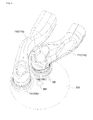
- FIG. 9 and FIG. 10 are diagrams provided to explain an example where an intake port is opened/closed by a valve unit in an engine intake port structure according to an exemplary embodiment of the present disclosure.
- FIG. 9 illustrates the valve unit 160 at the intake port 120 right after being opened or right before being closed.
- the chamfer 130 makes a difference in a valve lift. That is, it can be seen that a much wider space is formed on a side c2 in which the chamfer 130 is offset rather than a side c1 in which the chamfer 130 is not offset. Thus, an air volume may be concentrated on the side c2 in which the chamfer 130 is offset, and a flow of an air volume may be relatively small on the side in which the chamfer 130 is not offset.
- FIG. 10 is a diagram illustrating that the valve unit 160 is sufficiently opened at the intake port 120. As illustrated in FIG. 10 , it can be seen that all of the valve opening widths in the valve unit 160 are increased to be similar in size. If the valve opening widths become similar and increased as such, an orifice effect disappears, and a swirl is not concentrated on any side of four sides of the valve unit 160 but is favorably supplied into the combustion chamber 170.
- FIG. 11 is a diagram provided to explain a direction of a swirl effect in an engine intake port structure according to an exemplary embodiment of the present disclosure.
- a space is secured on any one side, and air is introduced into the combustion chamber through the space.
- an air current introduced into the combustion chamber 170 through the first intake port 121 by the first chamfer 131 is supplied diagonally to a wall surface of the combustion chamber 170. Meanwhile, a flow of an air current is limited on the opposite side, which achieves an effect similar to forming a virtual partition wall.
- a swirl introduced through the first intake port 121 does not interfere with the glow plug 192.
- an air current introduced into the combustion chamber 170 through the second intake port 122 by the second chamfer 132 may proceed toward the middle of the center of the combustion chamber 170 and an inner wall of the combustion chamber 170.
- a swirl promotes mixing of the intake air and fuel.
- a swirl acts right before the valve unit 160 closes the intake port 120 or right after the valve unit 160 opens the intake port 120, a flow rate can be further increased due to an orifice effect.
- the chamfer 130 is formed to be offset, air flows into the space secured by offset and a swirl flow is weakened in the meantime.
- the engine intake port structure according to the present disclosure may be used in an engine of a construction machine which is not equipped with a diesel particulate filter (DPF).
- DPF diesel particulate filter
- a vortex (swirl) caused by the chamfer 130 is generated at a space adjacent to the intake valve as such, and, thus, the swirl is further strengthened at the end of the intake stroke. That is, if the intake valve is closed at the end of the intake stroke, a gap between the intake valve and the intake port becomes narrow and a flow rate is increased.
- the swirl is weakened by the chamfers 130 according to an exemplary embodiment of the present disclosure.
- the swirl is weakened at the end of the intake stroke by the chamfers 130 according to an exemplary embodiment of the present disclosure, at the time of injecting fuel, a sufficient combustion time can be secured, and nitrogen oxides as well as smoke can be reduced.
- the offset direction D of the chamfer 130 formed at each intake port 120 may have various differences in angle along a rotation direction of a swirl.
- the engine intake port according to the present disclosure may be applied to a low swirl engine which is not equipped with a diesel particulate filter (DPF).
- DPF diesel particulate filter
- a valve sheet unit 150 is provided at an end corner of the intake port 110 on a side of the combustion chamber.
- the valve sheet unit 150 is brought into close contact with the valve unit 160 so as to maintain airtightness.
- the chamfer 130 may be formed at the valve sheet unit 150 so as to be inclined and offset with respect to the valve sheet unit 150. Further, in some cases, the chamfer 130 may be provided by rotating the chamfer 130 toward a direction of the valve sheet unit 150 such that an inclination direction of the chamfer 130 can be changed.
- Cycles of increase and decrease in an inclination angle of the chamfer 130 may continuously alternate, and an inclined plane of which an inclination angle increases and decreases along a circumferential direction of the valve sheet unit 150 may be formed at the chamfer 130.
- the inclined plane of the chamfer 130 may have a gentle surface on one side and a steep surface on the other side. On the gently inclined side, air smoothly flows, whereas on the steeply inclined side, a flow of air may be limited.
- the gently inclined surface of the chamfer 130 may be set to head for a flow direction of intake air through the intake port 110. Further, in order to adjust a level of strengthening a swirl by determining an operation state of the engine, the valve sheet unit 150 may be reassembled, and, thus, the inclination direction of the chamfer 130 may be adjusted.
- the chamfer 130 may be installed such that the gently inclined surface of the chamfer 130 heads for the opposite direction to the flow direction of intake air through the intake port 110 and the steeply inclined surface heads for the flow direction of intake air, and, thus, air escaping from the intake port 110 bumps against the steeply inclined surface of the chamfer 130 and inhibits formation of a swirl, thereby reducing swirls.
- the engine intake port structure according to the exemplary embodiment of the present disclosure weakens a swirl flow of intake air is weakened in an intake stroke, and, thus, it can be used in extending a waiting time in a combustion chamber.
Landscapes
- Engineering & Computer Science (AREA)
- Mechanical Engineering (AREA)
- General Engineering & Computer Science (AREA)
- Chemical & Material Sciences (AREA)
- Combustion & Propulsion (AREA)
- Cylinder Crankcases Of Internal Combustion Engines (AREA)
Abstract
Description
- The present disclosure relates to an engine intake port structure, and more particularly, to an engine intake port structure that weakens a swirl flow of intake air during an intake stroke so as to extend a waiting time in a combustion chamber.
- Generally, an engine includes a cylinder block and a cylinder head block. In the cylinder block, a cylinder is formed, and in the cylinder head block, an intake port and an exhaust port are formed. Further, in the cylinder head block, an injector and a glow plug are provided. That is, air is introduced into a combustion chamber through the intake port and fuel is injected by the injector, so that the air and the fuel are mixed to form a mixed gas, and the mixed gas is exploded and burned by a compression stroke of a piston. After being burned, the mixed gas is discharged as an exhaust gas through the exhaust port.
- Hereinafter, referring to
FIG. 1 to FIG. 3 , a conventional engine intake port structure will be described. -
FIG. 1 is a diagram provided to explain a conventional engine intake port structure.FIG. 2 is a bottom view of a cylinder head block provided to explain the conventional engine intake port structure.FIG. 3 is a longitudinal cross-sectional view of an intake port provided to explain the conventional engine intake port structure. - As illustrated in
FIG. 1 , anintake manifold 1 is provided on one side of acylinder head block 3. Theintake manifold 1 is configured to suck fresh air from the outside or to be supplied with intake air by a turbocharger. Theintake manifold 1 and acombustion chamber 4 are connected to each other by first andsecond intake ports cylinder head block 3, anintake port 5 and anexhaust port 7 are formed, and theintake port 5 and theexhaust port 7 are disposed within thecombustion chamber 4. - The
intake port 5 is connected to the above-described first andsecond intake ports valve unit 8 is installed. That is, if thevalve unit 8 is opened at theintake port 5, fresh air is supplied into the combustion chamber, and if thevalve unit 8 closes theintake port 5, the combustion chamber is sealed. - Meanwhile, a
valve sheet 6 is provided at theintake port 5. When thevalve unit 8 is closed, thevalve sheet 6 is brought into close contact with thevalve unit 8 so as to maintain a sealed state of the combustion chamber. - Further, after a mixed gas including air and fuel is burned, an
exhaust port 7 is configured to exhaust the gas. Although not illustrated in detail, theexhaust port 7 is provided with an exhaust valve for opening/closing theexhaust port 7. - Furthermore, in the
cylinder head block 3, aninjector 9 is installed at a central portion of thecombustion chamber 4. Theinjector 9 is configured to inject fuel to the combustion chamber. - Also, in the
cylinder head block 3, aglow plug 10 may be installed so as to be close to theinjector 9. Theglow plug 10 is used to warm up fuel. - Meanwhile, intake air may be supplied to the
intake manifold 1. Such compressed air may have a swirl depending on a shape of a flow path while passing through the first andsecond intake ports - Meanwhile, as illustrated in
FIG. 3 , in the conventional engine intake port structure, a corner at an end of theintake port 5 may be formed in a linear fashion without a particular shape, or even if a chamber is formed, the chamber is provided in a concentric manner with an inner diameter of theintake port 5. - Therefore, when the
valve unit 8 is opened at theintake port 5, opening widths w1 and w2 are equal to each other at four sides of thevalve unit 8 regardless of a position of a level of thevalve unit 8. - Meanwhile, at the time when the
valve unit 8 is opened, the opening widths w1 and w2 are narrow, and thus, the intake air is introduced into the combustion chamber at a high pressure while the swirls are formed in the intake air. The intake air introduced as such flows and is mixed with fuel. - Further, a
glow plug 10 may be provided in thecombustion chamber 4. That is, the intake air may be supplied toward a space where theglow plug 10 is disposed. Thus, the intake air may cause interference with theglow plug 10 and the swirl may be randomly scattered, so that the intake air and the fuel may not be mixed well. - Otherwise, as one of important considerations in developing a combustion unit of an engine, a vortex flow, i.e., a swirl flow, of air sucked into a combustion chamber is important. This is because only when the swirl flow of the intake air is big enough, the air and fuel can be smoothly mixed and smoke can be reduced.
- As components for generating a swirl, there are the first and
second intake ports first intake port 2a may be provided as a helical port, so that a swirl is generated while the intake air passes through thefirst intake port 2a. Further, thesecond intake port 2b is disposed such that the intake air can be introduced in a tangential direction from an edge of the combustion chamber, and, thus, the intake air forms a swirl itself while passing through thesecond intake port 2b. - However, as described above, in order to generate swirls by the first and
second intake ports - Therefore, the swirl flow ratio increases as the opening width of the intake valve increases in the middle of an intake stroke. However, toward the end of the intake stroke, as the intake valve is closed, an air volume decreases and a swirl of air sucked through an intake port becomes gradually smaller. Further, if the length of time during which air remains in a combustion chamber is short due to a swirl flow, there may be a problem of incomplete combustion.
- An embodiment of the present disclosure is suggested to solve the above-described problem. An object of the present disclosure is to provide an engine intake port structure in which a chamfer is formed to be offset to an end corner of an intake port, and, thus, a swirl flow of intake air is weakened at the end of an intake stroke so as to allow the air to remain in a combustion chamber for a long time.
- An engine intake port structure according to the present disclosure in order to achieve the above-described technical object includes: a
cylinder head block 100 including anintake port 110 and anexhaust port 140; aninjector 182 installed at a central portion of acombustion chamber 170 in thecylinder head block 100 and configured to inject fuel; and avalve unit 160 installed in thecylinder head block 100 and configured to open and close theintake port 110,
wherein at an end corner of theintake port 110, achamfer 130 is formed to be offset (a) with respect to the center of theintake port 110, and when theintake port 110 is opened/closed by thevalve unit 160, introduction of intake air is concentrated on a side in which an opening width of thechamfer 130 is wide at the beginning of an opening stage, and after theintake port 110 is opened, opening widths are formed to be similar at four sides of thevalve unit 160, so that a swirl formed in the intake air is weakened. - Further, in the engine intake port structure according to an exemplary embodiment of the present disclosure, the
intake port 110 may be provided in multiple as first andsecond intake ports first intake port 111, afirst chamfer 131 may be formed to be offset (a) with respect to the center of thefirst intake port 111 and at an end corner of thesecond intake port 112, asecond chamfer 132 may be formed to be offset (a) with respect to the center of thesecond intake port 112. - Furthermore, in the engine intake port structure according to an exemplary embodiment of the present disclosure, offset directions D and D1 of the
first chamfer 131 may be opposite to offset directions D and D2 of thesecond chamfer 132 by 180 degrees. - Also, in the engine intake port structure according to an exemplary embodiment of the present disclosure, when a virtual line connecting the center of the combustion chamber to the center of another adjacent combustion chamber is defined as a base line BL, the offset directions D of the first and
second chamfers - Further, in the engine intake port structure according to an exemplary embodiment of the present disclosure, the
intake port 110 may be provided in multiple as first andsecond intake ports first intake port 111 may be connected to afirst intake port 121 and thesecond intake port 112 may be connected to asecond intake port 122, and thefirst intake port 121 may be a helical port formed in a helical direction with respect to thecombustion chamber 170 and thesecond intake port 122 may be a tangential port formed in a tangential direction with respect to thecombustion chamber 170. - Furthermore, a diesel engine intake port structure according to another exemplary embodiment of the present disclosure which is formed to have torsion to control a swirl flow of a mixed gas includes: a
cylinder head block 100 including afirst intake port 111 and asecond intake port 112 adjacent to thefirst intake port 111; first andsecond intake ports valve sheet units 160 provided in thecylinder head block 100 and installed between the first andsecond intake ports second intake ports chamfers 130 which are formed such that an inclination angle toward a combustion chamber from the environs of the first andsecond intake ports chamfer 130 formed at thefirst intake port 111 is opposite to an inclination direction of thechamfer 130 formed at the adjacentsecond intake port 112. - Further, in the diesel engine intake port structure according to an exemplary embodiment of the present disclosure, the first and
second intake ports cylinder head block 100 and a tangential port arranged in a tangential direction at an edge of the combustion chamber. - Furthermore, in the diesel engine intake port structure according to an exemplary embodiment of the present disclosure, the inclination direction of the
chamfer 130 formed at thefirst intake port 111 may be twisted by 30 degrees in an anticlockwise direction based on a longitudinal direction of thecylinder head block 100 and the inclination direction of thechamfer 130 formed at thesecond intake port 112 may be twisted by 210 degrees in the anticlockwise direction based on the longitudinal direction of thecylinder head block 100. - A first effect of the present disclosure is that a swirl flow of intake air can be weakened by a simple structure. A second effect of the present disclosure is that efficiency of an engine can be improved and contaminants in an exhaust gas can be reduced by increasing mixability between fuel and air.
-
-
FIG. 1 is a diagram provided to explain a conventional engine intake port structure. -
FIG. 2 is a bottom view of a cylinder head block provided to explain the conventional engine intake port structure. -
FIG. 3 is a longitudinal cross-sectional view of an intake port provided to explain the conventional engine intake port structure. -
FIG. 4 andFIG. 5 are bottom views of a cylinder head block provided to explain an engine intake port structure according to an exemplary embodiment of the present disclosure. -
FIG. 6 is a diagram provided to explain an intake port formed at a cylinder head block in an engine intake port structure according to an exemplary embodiment of the present disclosure. -
FIG. 7 is a diagram provided to explain a chamfer formed at an intake port in an engine intake port structure according to an exemplary embodiment of the present disclosure. -
FIG. 8 is a cross-sectional view taken along a line A-A ofFIG. 7 . -
FIG. 9 andFIG. 10 are diagrams provided to explain an example where an intake port is opened/closed by a valve unit in an engine intake port structure according to an exemplary embodiment of the present disclosure. -
FIG. 11 is a diagram provided to explain a direction of a swirl effect in an engine intake port structure according to an exemplary embodiment of the present disclosure. -
FIG. 12 is a diagram provided to explain a swirl ratio as compared with a valve lift when offset directions of first and second chamfers have torsion angles, respectively, with respect to a base line BL in an engine intake port structure according to an exemplary embodiment of the present disclosure. -
1: Intake manifold 2a, 2b: First and second intake ports 3: Cylinder head block 4: Combustion chamber 5: Intake port 6: Valve sheet unit 7: Exhaust port 8: Valve unit 9: Injector 10: Glow plug w1, w2: First and second opening widths 100: Cylinder head block 110: Intake port 111, 112: First and second intake ports 121, 122: First and second intake ports 130: Chamfer 131, 132: First and second chamfers 140: Exhaust port 142: Exhaust port 150: Valve unit 160: Valve sheet unit 170: Combustion chamber 180: Injector installation hole 182: Injector 190: Glow plug installation hole 192: Glow plug BL: Base line (Line connecting the center of a combustion chamber and the center of another combustion chamber) a: Offset distance b1, b2: Torsion angle with respect to base line c1, c2: First and second opening widths - The advantages and characteristics of the present disclosure and methods for achieving the same will become clear from the embodiments set forth in detail below with reference to the attached drawings.
- Hereinafter, exemplary embodiments of the present disclosure will be described in detail with reference to the accompanying drawings. It should be understood that the following exemplary embodiments are provided for illustration to help improve understanding of the present disclosure, and the invention may be embodied in many different forms from the exemplary embodiments set forth herein. In the following description, a detailed explanation of known related functions and constructions may be omitted to avoid unnecessarily obscuring the subject matter of the present disclosure. Further, the drawings are not necessarily to scale and certain features may be exaggerated in order to more clearly illustrate and explain the present disclosure.
- Also, the terms described below are established taking into account the functions of the present disclosure. Since the terms may be changed in accordance with manufacturer's intention or practice, the meanings of the terms should be defined based on the whole contents of the specification.
- Throughout the whole specification, the same reference numerals denote the same elements.
- Hereinafter, an engine intake port structure according to an exemplary embodiment of the present disclosure will be described with reference to
FIG. 4 to FIG. 8 . -
FIG. 4 andFIG. 5 are bottom views of a cylinder head block provided to explain an engine intake port structure according to an exemplary embodiment of the present disclosure.FIG. 6 is a diagram provided to explain an intake port formed at a cylinder head block in an engine intake port structure according to an exemplary embodiment of the present disclosure.FIG. 7 is a diagram provided to explain a chamfer formed at an intake port in an engine intake port structure according to an exemplary embodiment of the present disclosure.FIG. 8 is a cross-sectional view taken along a line A-A ofFIG. 7 . - As illustrated in
FIG. 4 , at a bottom surface of acylinder head block 100, anintake port 110 and anintake port 120 are formed. Further, at a central portion of a combustion chamber, aninjector 182 is provided. Meanwhile, an engine may include multiple combustion chambers, and for example, four, six or more combustion chambers may be provided. - Meanwhile, a cylinder may be formed to be upright or formed into a V-shape depending on the specifications of the engine. If the cylinder is formed to be upright, multiple combustion chambers may be arranged in a row. Further, even if the cylinder is formed into a V-shape, combustion chambers may be arranged in a row. In an exemplary embodiment of the present disclosure, a line connecting the center of a combustion chamber to the center of another combustion chamber will be defined and explained as a base line BL.
-
FIG. 5 is a diagram simply illustrating onecombustion chamber 170 in thecylinder head block 100. - As illustrated in
FIG. 5 , theintake port 110 and anexhaust port 142 are formed in thecylinder head block 100. Theintake port 110 may be provided in multiple as first andsecond intake ports - At an end portion of the
intake port 110, theintake port 120 is formed. That is, at end portions of the first andsecond intake ports second intake ports - Meanwhile, although not specifically illustrated, the
intake port 110 is connected to an intake manifold so as to be supplied with intake air. As a result, the intake air is supplied to thecombustion chamber 170 from theintake port 120 via theintake port 110. - Further, at an end portion of the
exhaust port 142, anexhaust port 140 is formed. Theexhaust port 140 is configured to discharge an exhaust gas after combustion is completed in thecombustion chamber 170. - Within the
cylinder head block 100, aninjector installation hole 180 is formed at a central portion of thecombustion chamber 170. At theinjector installation hole 180, aninjector 182 is installed. Theinjector 182 is configured to inject fuel into the combustion chamber. - Further, in the
cylinder head block 100, a glowplug installation hole 190 is formed between theintake port 120 and theexhaust port 140. At the glowplug installation hole 190, aglow plug 192 is installed. Theglow plug 192 is configured to warm up fuel to assist ignition. - Meanwhile, as illustrated in
FIG. 5 andFIG. 7 , at an end corner of theintake port 120, achamfer 130 is formed. Thechamfer 130 may be formed to be offset to either side (refer to a). Herein, the chamfer refers to an inclined portion or an inclined plane. - Further, the
chamfer 130 may have various inclination angles and thus may have a gentle inclination angle or a sharp inclination angle. Furthermore, an inclination plane forming thechamfer 130 may have a flat surface or may have a bent or a protrusion in some cases. - The
chamfer 130 may be formed to have a right angle or an acute angle, preferably 45 degrees, with respect to an axis of theintake port 120. - If the inclination angle of the
chamfer 130 is equal to or greater than 45 degrees, a swirl flow is sharply reduced, and if the inclination angle is equal to or less than 45 degrees, a swirl flow is gradually reduced. - Thus, as illustrated in
FIG. 9 , when theintake port 110 is opened/closed by thevalve unit 160, introduction of intake air is concentrated on a side in which an opening width of thechamfer 130 is wide at the beginning of an opening stage or at the end of a closing stage. There is made a difference in opening width at four sides of thevalve unit 160 due to thechamfer 130. That is, a flow of an air volume toward a side in which an opening width c1 is narrow is suppressed, and an air volume toward a side in which an opening width c2 is wide is concentrated. - Meanwhile, after the
intake port 120 is opened, as illustrated inFIG. 10 , opening widths are formed to be similar at four sides of thevalve unit 160, and, thus, an air volume is not concentrated on any particular portion but can be uniformly introduced. That is, a swirl formed in the intake air is weakened. - Otherwise, an offset distance a may be in a range of 0.5 mm to 3 mm. If the offset distance a is too short, an effect caused by the
chamfer 130 is reduced, and, thus, preferably, the offset distance a may be 0.5 mm or more. Otherwise, if the offset distance a is too long, when thecylinder head block 120 and the cylinder block are combined to form thecombustion chamber 170, a gap may be formed. Therefore, preferably, the offset distance a may be 3 mm or less. Further, the offset distance a may vary in size depending on the specifications of the engine. - Further, the
intake port 110 may be provided in multiple as the first andsecond intake ports first intake port 111, afirst chamfer 131 is formed to be offset (a) with respect to the center of thefirst intake port 111. At an end corner of thesecond intake port 112, asecond chamfer 132 is formed to be offset (a) with respect to the center of thesecond intake port 112. That is, thechamfers 130 are formed at the twointake ports 120, respectively. Thus, an effect of thechamfers 130 on therespective intake ports 120 can be anticipated. - Meanwhile, the
first chamfer 131 and thesecond chamfer 132 may be equal to or different from each other in an inclination angle or a shape. - Further, in the engine intake port structure according to an exemplary embodiment of the present disclosure, an offset direction D1 of the
first chamfer 131 may be opposite to an offset direction D2 of thesecond chamfer 132 by 180 degrees. Thus, swirls are introduced into thecombustion chamber 170 through two places, and interference between these two swirls can be minimized. In addition, if two swirls are introduced in directions facing each other, the swirls may be rapidly dissipated due to mutual interference. However, in an exemplary embodiment of the present disclosure, the offset directions of the chamfers are arranged to be opposite to each other, and, thus, mutual interference between two swirls can be minimized and mixing of air and fuel can be further promoted by the swirls. - Otherwise, the offset directions D, D1, and D2 of the first and
second chamfers - The offset direction D1 of the
first chamfer 131 may be a direction twisted with respect to the base line BL by afirst angle b 1 from a bottom view directly showing a bottom surface of thecylinder head block 100. - In the same manner, the offset direction D2 of the
second chamfer 132 may be a direction twisted with respect to the base line BL by a second angle b1 from the bottom view directly showing the bottom surface of thecylinder head block 100. - Meanwhile, the first and second angles b1 and b2 may be parallel to the base line BL or may be smaller than 30 degrees. To be more specific, the first angle b1 may be within 30 degrees in an anticlockwise direction with respect to the base line BL from a direction in which the
intake port 120 can be directly seen from thecombustion chamber 170. Thus, intake air introduced through thefirst intake port 121 can smoothly maintain swirls within thecombustion chamber 170. - Further, the second angle b2 may be within 30 degrees in the anticlockwise direction with respect to the base line BL from the direction in which the
intake port 120 can be directly seen from thecombustion chamber 170. Thus, intake air introduced through thesecond intake port 122 can smoothly maintain swirls within thecombustion chamber 170. - For example, if the first angle b1 of the
first intake port 121 is twisted by 30 degrees in an anticlockwise direction, the second angle b2 of thesecond intake port 122 can be twisted by 210 degrees in the anticlockwise direction. - Details thereof will be described with reference to
FIG. 12. FIG. 12 is a diagram provided to explain a swirl ratio as compared with a valve lift when offset directions of first and second chamfers have torsion angles, respectively, with respect to a base line BL in an engine intake port structure according to an exemplary embodiment of the present disclosure. -
FIG. 12 illustrates first, second, and third examples. In the first example, the offset direction D is parallel to the base line BL. In the second example, the offset direction D is twisted by 30 degrees with respect to the base line BL. In the third example, the offset direction D is twisted by 20 degrees with respect to the base line BL. Meanwhile, when the chamfer is formed in a concentric manner without being offset, there is little change in swirl ratio. - Meanwhile,
FIG. 12 illustrates an example where a valve lift is 0 in a closed state and 5 mm in a maximum open state. Hereinafter, there will be described an example where a valve lift is set to 0% in a closed state and 100% in a maximum open state. - According to the first example (a), it can be seen that a swirl ratio is gradually and continuously increased from a time when the valve unit is opened, and when a valve lift reaches 90%, the swirl ratio is sharply increased. That is, according to the first example (a), it can be seen that since the first and
second chamfers - According to the second example (b), a swirl ratio is decreased at the beginning of an opening stage of the valve unit. Meanwhile, the swirl ratio is weakened until a valve lift reaches about 25%, and when the valve lift is 25% or more, the swirl ratio is gradually increased. When the valve lift reaches about 90%, the swirl ratio tends to be increased. In particular, in the second example (b) as compared with the first example (a), the swirl ratio is remarkably low throughout the section of the valve lift.
- According to the third example (c), there is a slight change in a swirl ratio at the beginning of an opening stage of the valve unit, and when a valve lift reaches about 25%, the swirl ratio is gradually increased, and when the valve lift reaches about 90%, the swirl ratio tends to be increased. However, it can be seen that the third example (c) exhibits a weakened swirl ratio as compared with the first example (a) but exhibits a relatively high swirl ratio as compared with the second example (b).
- As described, it can be seen that a swirl ratio may vary depending on a torsion angle of the offset directions D, D1, and D2 of the first and
second chamfers - The
intake port 110 will be described with reference toFIG. 6 . As described above, theintake port 110 may be provided in multiple as the first andsecond intake ports - The
first intake port 111 may be a tangential port, and an introduction direction of an air current may be a tangential direction of thecombustion chamber 170. Thus, if air is introduced into thecombustion chamber 170 through thefirst intake port 121 via thefirst intake port 111, the air naturally forms a swirl within thecombustion chamber 170. - The
second intake port 112 may be a helical port provided in a helical shape. Thus, air forms a swirl itself while passing through thesecond intake port 112, and the air is introduced into thecombustion chamber 170 in a swirl state while passing through thesecond intake port 122. - That is, the first and
second intake ports combustion chamber 170. - Hereinafter, an example where an opening width of a valve is changed depending on opening/closing of the
valve unit 160 in the engine intake port structure according to an exemplary embodiment of the present disclosure will be described in more detail. -
FIG. 9 andFIG. 10 are diagrams provided to explain an example where an intake port is opened/closed by a valve unit in an engine intake port structure according to an exemplary embodiment of the present disclosure. -
FIG. 9 illustrates thevalve unit 160 at theintake port 120 right after being opened or right before being closed. As illustrated inFIG. 9 , thechamfer 130 makes a difference in a valve lift. That is, it can be seen that a much wider space is formed on a side c2 in which thechamfer 130 is offset rather than a side c1 in which thechamfer 130 is not offset. Thus, an air volume may be concentrated on the side c2 in which thechamfer 130 is offset, and a flow of an air volume may be relatively small on the side in which thechamfer 130 is not offset. -
FIG. 10 is a diagram illustrating that thevalve unit 160 is sufficiently opened at theintake port 120. As illustrated inFIG. 10 , it can be seen that all of the valve opening widths in thevalve unit 160 are increased to be similar in size. If the valve opening widths become similar and increased as such, an orifice effect disappears, and a swirl is not concentrated on any side of four sides of thevalve unit 160 but is favorably supplied into thecombustion chamber 170. - Hereinafter, an effect of a swirl will be described with reference to
FIG. 11. FIG. 11 is a diagram provided to explain a direction of a swirl effect in an engine intake port structure according to an exemplary embodiment of the present disclosure. - Since the
chamfer 130 is formed to be offset, a space is secured on any one side, and air is introduced into the combustion chamber through the space. InFIG. 11 , as for a direction of a swirl effect, an air current introduced into thecombustion chamber 170 through thefirst intake port 121 by thefirst chamfer 131 is supplied diagonally to a wall surface of thecombustion chamber 170. Meanwhile, a flow of an air current is limited on the opposite side, which achieves an effect similar to forming a virtual partition wall. Thus, a swirl introduced through thefirst intake port 121 does not interfere with theglow plug 192. - Further, an air current introduced into the
combustion chamber 170 through thesecond intake port 122 by thesecond chamfer 132 may proceed toward the middle of the center of thecombustion chamber 170 and an inner wall of thecombustion chamber 170. Thus, a swirl promotes mixing of the intake air and fuel. - Meanwhile, if a swirl acts right before the
valve unit 160 closes theintake port 120 or right after thevalve unit 160 opens theintake port 120, a flow rate can be further increased due to an orifice effect. However, since thechamfer 130 is formed to be offset, air flows into the space secured by offset and a swirl flow is weakened in the meantime. - Further, the engine intake port structure according to the present disclosure may be used in an engine of a construction machine which is not equipped with a diesel particulate filter (DPF).
- If air sucked into the
combustion chamber 170 through theintake port 110 by thechamfers 130 formed at the bottom of the first andsecond intake ports combustion chamber 170 through theintake valve 160, a swirl flow is weakened. - A vortex (swirl) caused by the
chamfer 130 is generated at a space adjacent to the intake valve as such, and, thus, the swirl is further strengthened at the end of the intake stroke. That is, if the intake valve is closed at the end of the intake stroke, a gap between the intake valve and the intake port becomes narrow and a flow rate is increased. The swirl is weakened by thechamfers 130 according to an exemplary embodiment of the present disclosure. - Since the swirl is weakened at the end of the intake stroke by the
chamfers 130 according to an exemplary embodiment of the present disclosure, at the time of injecting fuel, a sufficient combustion time can be secured, and nitrogen oxides as well as smoke can be reduced. - Further, if the
multiple intake ports 120 are formed in thesingle combustion chamber 170, the offset direction D of thechamfer 130 formed at eachintake port 120 may have various differences in angle along a rotation direction of a swirl. - Furthermore, the engine intake port according to the present disclosure may be applied to a low swirl engine which is not equipped with a diesel particulate filter (DPF).
- Meanwhile, a
valve sheet unit 150 is provided at an end corner of theintake port 110 on a side of the combustion chamber. When theintake port 110 is closed by thevalve unit 160, thevalve sheet unit 150 is brought into close contact with thevalve unit 160 so as to maintain airtightness. - Otherwise, the
chamfer 130 may be formed at thevalve sheet unit 150 so as to be inclined and offset with respect to thevalve sheet unit 150. Further, in some cases, thechamfer 130 may be provided by rotating thechamfer 130 toward a direction of thevalve sheet unit 150 such that an inclination direction of thechamfer 130 can be changed. - Cycles of increase and decrease in an inclination angle of the
chamfer 130 may continuously alternate, and an inclined plane of which an inclination angle increases and decreases along a circumferential direction of thevalve sheet unit 150 may be formed at thechamfer 130. - Therefore, the inclined plane of the
chamfer 130 may have a gentle surface on one side and a steep surface on the other side. On the gently inclined side, air smoothly flows, whereas on the steeply inclined side, a flow of air may be limited. - According to another exemplary embodiment of the present disclosure, the gently inclined surface of the
chamfer 130 may be set to head for a flow direction of intake air through theintake port 110. Further, in order to adjust a level of strengthening a swirl by determining an operation state of the engine, thevalve sheet unit 150 may be reassembled, and, thus, the inclination direction of thechamfer 130 may be adjusted. - The
chamfer 130 may be installed such that the gently inclined surface of thechamfer 130 heads for the opposite direction to the flow direction of intake air through theintake port 110 and the steeply inclined surface heads for the flow direction of intake air, and, thus, air escaping from theintake port 110 bumps against the steeply inclined surface of thechamfer 130 and inhibits formation of a swirl, thereby reducing swirls. - The present disclosure is not limited to the above-described specific exemplary embodiments and can be modified and changed in various ways by those having ordinary skill in the art without departing from the subject matter of the present disclosure as claimed in the following claims and such changes and modifications fall within the scope of the claims.
- The engine intake port structure according to the exemplary embodiment of the present disclosure weakens a swirl flow of intake air is weakened in an intake stroke, and, thus, it can be used in extending a waiting time in a combustion chamber.
Claims (8)
- An engine intake port structure comprising:a cylinder head block (100) comprising an intake port (110) and an exhaust port (140); anda valve unit (160) installed in the cylinder head block (100) and configured to open and close the intake port (110),wherein at an end corner of the intake port (110), a chamfer (130) is formed to be offset (a) with respect to the center of the intake port (110), and when the intake port (110) is opened/closed by the valve unit (160), introduction of intake air is concentrated on a side in which an opening width of the chamfer (130) is wide at the beginning of an opening stage or at the end of a closing stage, and after the intake port (110) is opened, opening widths are formed to be similar at four sides of the valve unit (160), so that a swirl formed in the intake air is weakened.
- The engine intake port structure of claim 1, wherein the intake port (110) is provided in multiple as first and second intake ports (111, 112), and at an end corner of the first intake port (111), a first chamfer (131) is formed to be offset (a) with respect to the center of the first intake port (111) and at an end corner of the second intake port (112), a second chamfer (132) is formed to be offset (a) with respect to the center of the second intake port (112).
- The engine intake port structure of claim 2, wherein an offset direction (D1) of the first chamfer (131) is opposite to an offset direction (D2) of the second chamfer (132) by 180 degrees.
- The engine intake port structure of claim 2 or claim 3, wherein when a virtual line connecting the center of the combustion chamber to the center of another adjacent combustion chamber is defined as a base line (BL), the offset directions (D1, D2) of the first and second chamfers (131, 132) have torsion angles (b1, b2), respectively, with respect to the base line (BL).
- The engine intake port structure of claim 1, wherein the intake port (110) is provided in multiple as first and second intake ports (111, 112), and the first intake port (111) is connected to a first intake port (121) and the second intake port (112) is connected to a second intake port (122), and the first intake port (121) is a helical port formed in a helical direction with respect to the combustion chamber (170) and the second intake port (122) is a tangential port formed in a tangential direction with respect to the combustion chamber (170).
- A diesel engine intake port structure which is formed to have torsion to control a swirl flow of a mixed gas, the diesel engine intake port structure comprising:a cylinder head block (100) comprising a first intake port (111) and a second intake port (112) adjacent to the first intake port (111);first and second intake ports (121, 122) connected to the intake ports and configured to suck air;valve sheet units (160) provided in the cylinder head block (100) and installed between the first and second intake ports (121, 122) and the first and second intake ports (111, 112); andchamfers (130) which are formed such that an inclination angle toward a combustion chamber from the environs of the first and second intake ports (111, 112) is changed, wherein an inclination direction of the chamfer (130) formed at the first intake port (111) is opposite to an inclination direction of the chamfer (130) formed at the adjacent second intake port (112).
- The diesel engine intake port structure of claim 6, wherein the first and second intake ports (121, 122) comprise a helical port installed in a helical shape in the cylinder head block (100) and a tangential port arranged in a tangential direction at an edge of the combustion chamber.
- The diesel engine intake port structure of claim 6, wherein the inclination direction of the chamfer (130) formed at the first intake port (111) is twisted by 30 degrees in an anticlockwise direction based on a longitudinal direction of the cylinder head block (100) and the inclination direction of the chamfer (130) formed at the second intake port (112) is twisted by 210 degrees in the anticlockwise direction based on the longitudinal direction of the cylinder head block (100).
Applications Claiming Priority (2)
| Application Number | Priority Date | Filing Date | Title |
|---|---|---|---|
| KR20120152970 | 2012-12-26 | ||
| PCT/KR2013/012192 WO2014104750A1 (en) | 2012-12-26 | 2013-12-26 | Engine intake port structure |
Publications (3)
| Publication Number | Publication Date |
|---|---|
| EP2940268A1 true EP2940268A1 (en) | 2015-11-04 |
| EP2940268A4 EP2940268A4 (en) | 2017-03-01 |
| EP2940268B1 EP2940268B1 (en) | 2020-02-05 |
Family
ID=51735986
Family Applications (1)
| Application Number | Title | Priority Date | Filing Date |
|---|---|---|---|
| EP13866707.6A Active EP2940268B1 (en) | 2012-12-26 | 2013-12-26 | Engine intake port structure |
Country Status (5)
| Country | Link |
|---|---|
| US (1) | US9719410B2 (en) |
| EP (1) | EP2940268B1 (en) |
| KR (1) | KR102058755B1 (en) |
| CN (1) | CN104583559B (en) |
| WO (1) | WO2014104750A1 (en) |
Cited By (3)
| Publication number | Priority date | Publication date | Assignee | Title |
|---|---|---|---|---|
| EP3517764A1 (en) * | 2018-01-24 | 2019-07-31 | Mazda Motor Corporation | Cylinder head of engine, internal combustion engine and method of producing cylinder head |
| EP4155527A3 (en) * | 2021-09-28 | 2023-04-12 | JCB Research | Internal combustion engine |
| WO2024160431A1 (en) * | 2023-01-30 | 2024-08-08 | Daimler Truck AG | Internal combustion engine for a motor vehicle and motor vehicle, in particular commercial vehicle, having such an internal combustion engine |
Families Citing this family (18)
| Publication number | Priority date | Publication date | Assignee | Title |
|---|---|---|---|---|
| US9657633B2 (en) * | 2012-04-25 | 2017-05-23 | International Engine Intellectual Property Company, Llc. | Swirl-inducing intake valve arrangement |
| KR102058755B1 (en) * | 2012-12-26 | 2020-01-22 | 두산인프라코어 주식회사 | Intake port of diesel engine |
| EP3161295A4 (en) * | 2014-06-30 | 2018-03-21 | Cummins, Inc. | System and method for valve size ratio and igniter placement |
| JP6319170B2 (en) | 2015-04-30 | 2018-05-09 | トヨタ自動車株式会社 | Multi-cylinder engine |
| CN105240143A (en) * | 2015-11-02 | 2016-01-13 | 重庆金花玻璃钢有限公司 | Engine cylinder cover capable of increasing swirl ratio |
| CN105240140A (en) * | 2015-11-02 | 2016-01-13 | 重庆金花玻璃钢有限公司 | Engine cylinder cover capable of enhancing air and fuel oil mixing effect |
| CN105240142A (en) * | 2015-11-02 | 2016-01-13 | 重庆金花玻璃钢有限公司 | Engine cylinder head capable of increasing swirl rate and easy to repair |
| JP2017110604A (en) * | 2015-12-17 | 2017-06-22 | ヤマハ発動機株式会社 | Internal combustion engine, vehicle including the same, and method for manufacturing internal combustion engine |
| CN106441911B (en) * | 2016-06-29 | 2019-01-04 | 中国北方发动机研究所(天津) | Diesel engine intake swirl adjustable test device |
| CN106014673A (en) * | 2016-08-04 | 2016-10-12 | 广西玉柴机器股份有限公司 | Diesel engine cylinder head |
| EP3567238A4 (en) * | 2017-03-03 | 2020-01-15 | Mazda Motor Corporation | Intake port structure for internal combustion engine |
| CN107035579A (en) * | 2017-04-14 | 2017-08-11 | 无锡开普机械有限公司 | Oil to gas gas engine inlet structure |
| KR102365183B1 (en) | 2017-06-15 | 2022-02-18 | 현대자동차 주식회사 | Intake port of engine |
| CN108590872B (en) * | 2018-03-30 | 2019-09-27 | 潍柴动力股份有限公司 | Valve seat ring bottom hole of cylinder head and cylinder head |
| US11060425B2 (en) * | 2019-03-13 | 2021-07-13 | Caterpillar Inc. | Valve seat insert for engine head having venturi flow crowns and seating surface profiled for limiting valve recession |
| CN113404612B (en) * | 2021-08-19 | 2021-12-21 | 潍柴动力股份有限公司 | Engine cylinder cover and gas engine |
| US11655777B2 (en) * | 2021-09-07 | 2023-05-23 | Southwest Research Institute | Parallel intake valve tumble flow engine |
| CN117300185A (en) * | 2022-06-24 | 2023-12-29 | 康明斯公司 | Cylinder head offset chamfer design |
Family Cites Families (41)
| Publication number | Priority date | Publication date | Assignee | Title |
|---|---|---|---|---|
| FR2015574A1 (en) * | 1968-08-13 | 1970-04-30 | Nissan Diesel Motor | |
| US4121544A (en) * | 1975-01-24 | 1978-10-24 | May Michael G | Internal combustion engine |
| US4354463A (en) * | 1979-06-09 | 1982-10-19 | Honda Giken Kogyo Kabushiki Kaisha | Device for improving combustion efficiency of mixture in four cycle internal combustion engine |
| DE3141663A1 (en) | 1981-10-21 | 1983-05-05 | Bayerische Motoren Werke AG, 8000 München | Mixture-compressing, spark-ignition internal combustion engine |
| DD234998A3 (en) * | 1983-04-19 | 1986-04-23 | Ifa Motorenwerke | CYLINDER HEAD WITH INTAKE DUCT CHANNEL |
| JPH086585B2 (en) * | 1987-01-13 | 1996-01-24 | トヨタ自動車株式会社 | 2-cycle internal combustion engine |
| ATE115238T1 (en) * | 1991-08-07 | 1994-12-15 | Avl Verbrennungskraft Messtech | MULTI-CYLINDER ENGINE WITH INTERNAL MIXTURE. |
| JPH0560038A (en) * | 1991-08-26 | 1993-03-09 | Mazda Motor Corp | Engine fuel supplying device |
| JP3491762B2 (en) * | 1991-10-09 | 2004-01-26 | 株式会社小松製作所 | Cylinder head structure of internal combustion engine |
| EP0619424B1 (en) * | 1993-04-05 | 1997-03-05 | Isuzu Motors Limited | Multi-intake valve engine |
| JP3300910B2 (en) * | 1994-02-04 | 2002-07-08 | マツダ株式会社 | Direct injection diesel engine |
| JP3517957B2 (en) * | 1994-06-10 | 2004-04-12 | マツダ株式会社 | Engine intake port structure and its setting method |
| US5765525A (en) * | 1994-12-15 | 1998-06-16 | Ford Global Technologies, Inc. | Intake system for an internal combustion engine |
| DE19535147C2 (en) * | 1995-09-21 | 2002-07-11 | Meta Motoren Energietech | Reciprocating internal combustion engine with at least one cylinder |
| DE19540398C1 (en) * | 1995-10-30 | 1997-03-27 | Daimler Benz Ag | Cylinder head for internal combustion engines |
| EP0790398B1 (en) * | 1996-02-16 | 2002-05-15 | Isuzu Motors Limited | Engine having a plurality of intake ports for each cylinder |
| DE59705848D1 (en) * | 1996-06-20 | 2002-01-31 | Volkswagen Ag | Method and device for operating a spark-ignition reciprocating internal combustion engine |
| JPH10103066A (en) * | 1996-09-30 | 1998-04-21 | Mazda Motor Corp | Engine intake system |
| JP3575337B2 (en) | 1999-06-30 | 2004-10-13 | 日産自動車株式会社 | Combustion chamber of internal combustion engine |
| JP3807207B2 (en) * | 1999-12-24 | 2006-08-09 | いすゞ自動車株式会社 | Multi-valve intake engine |
| WO2001055567A1 (en) * | 2000-01-25 | 2001-08-02 | Kabushiki Kaisha Toyota Chuo Kenkyusho | Direct injection type internal combustion engine |
| AT4876U1 (en) * | 2000-05-04 | 2001-12-27 | Avl List Gmbh | INTERNAL COMBUSTION ENGINE WITH AT LEAST TWO INLET CHANNELS PER CYLINDER |
| US6318348B1 (en) * | 2000-06-08 | 2001-11-20 | Visteon Global Technologies, Inc. | Stratified exhaust gas recirculation strategy for internal combustion engine |
| US6321715B1 (en) * | 2000-06-23 | 2001-11-27 | Visteon Global Technologies, Inc. | Conjugate vortex stratified exhaust gas recirculation system for internal combustion engine |
| JP3676967B2 (en) | 2000-08-14 | 2005-07-27 | 新潟原動機株式会社 | cylinder head |
| AT5781U1 (en) * | 2001-04-19 | 2002-11-25 | Avl List Gmbh | INTERNAL COMBUSTION ENGINE WITH AT LEAST ONE INLET VALVE |
| FR2856743B1 (en) * | 2003-06-30 | 2005-10-14 | Renault Sa | INTAKE CIRCUIT HAVING TANGENTIALLY GAS ORIENTATION MEANS FOR THE SWIRL MOVEMENT |
| KR20050039965A (en) | 2003-10-27 | 2005-05-03 | 현대자동차주식회사 | An air intake system in engine |
| DE112005001955B4 (en) * | 2004-08-19 | 2020-03-05 | Avl List Gmbh | Internal combustion engine |
| US7434564B2 (en) * | 2004-08-19 | 2008-10-14 | Avl List Gmbh | Internal combustion engine |
| JP4556771B2 (en) * | 2005-05-27 | 2010-10-06 | 三菱自動車工業株式会社 | Engine combustion chamber structure |
| FR2887585A1 (en) * | 2005-06-22 | 2006-12-29 | Renault Sas | DEVICE FOR INTERNAL COMBUSTION ENGINE FOR VARYING AERODYNAMIC GENERATION IN CYLINDER HEAD DELIVERY DUCTS |
| JP4680828B2 (en) * | 2006-05-11 | 2011-05-11 | 本田技研工業株式会社 | Engine intake port structure |
| JP2008115771A (en) | 2006-11-06 | 2008-05-22 | Denso Corp | Intake control device for internal combustion engine |
| JP4730355B2 (en) * | 2007-08-29 | 2011-07-20 | トヨタ自動車株式会社 | Internal combustion engine port and port manufacturing method |
| FR2923865A1 (en) | 2007-11-15 | 2009-05-22 | Renault Sas | Cylinder cover for e.g. petrol engine, has connection including connecting surface extending between lateral surface of housing and cylinder head and presenting inclined pan inclined along part of front edge of inlet orifice |
| FR2929990B1 (en) | 2008-04-09 | 2010-05-21 | Peugeot Citroen Automobiles Sa | INTERNAL COMBUSTION ENGINE COMPRISING CHAMFER INJECTION DUCTS |
| DE102009043479A1 (en) | 2009-09-30 | 2011-03-31 | Volkswagen Ag | Self-igniting internal combustion engine has cylinder, injection system for direct fuel injection in combustion chamber of cylinder and exhaust gas turbocharger |
| JP5381913B2 (en) * | 2010-06-29 | 2014-01-08 | マツダ株式会社 | Engine cylinder head structure |
| EP2698508A1 (en) * | 2012-08-17 | 2014-02-19 | MWM GmbH | Cylinder head with countersink |
| KR102058755B1 (en) * | 2012-12-26 | 2020-01-22 | 두산인프라코어 주식회사 | Intake port of diesel engine |
-
2013
- 2013-12-26 KR KR1020130163701A patent/KR102058755B1/en active Active
- 2013-12-26 CN CN201380044988.5A patent/CN104583559B/en active Active
- 2013-12-26 US US14/655,515 patent/US9719410B2/en active Active
- 2013-12-26 WO PCT/KR2013/012192 patent/WO2014104750A1/en not_active Ceased
- 2013-12-26 EP EP13866707.6A patent/EP2940268B1/en active Active
Cited By (5)
| Publication number | Priority date | Publication date | Assignee | Title |
|---|---|---|---|---|
| EP3517764A1 (en) * | 2018-01-24 | 2019-07-31 | Mazda Motor Corporation | Cylinder head of engine, internal combustion engine and method of producing cylinder head |
| US10655531B2 (en) | 2018-01-24 | 2020-05-19 | Mazda Motor Corporation | Cylinder head of engine |
| EP4155527A3 (en) * | 2021-09-28 | 2023-04-12 | JCB Research | Internal combustion engine |
| US12480436B2 (en) | 2021-09-28 | 2025-11-25 | JCB Research | Internal combustion engine |
| WO2024160431A1 (en) * | 2023-01-30 | 2024-08-08 | Daimler Truck AG | Internal combustion engine for a motor vehicle and motor vehicle, in particular commercial vehicle, having such an internal combustion engine |
Also Published As
| Publication number | Publication date |
|---|---|
| EP2940268A4 (en) | 2017-03-01 |
| CN104583559A (en) | 2015-04-29 |
| WO2014104750A1 (en) | 2014-07-03 |
| CN104583559B (en) | 2017-03-29 |
| US9719410B2 (en) | 2017-08-01 |
| KR20140086873A (en) | 2014-07-08 |
| EP2940268B1 (en) | 2020-02-05 |
| KR102058755B1 (en) | 2020-01-22 |
| US20150345420A1 (en) | 2015-12-03 |
Similar Documents
| Publication | Publication Date | Title |
|---|---|---|
| EP2940268B1 (en) | Engine intake port structure | |
| JP4549222B2 (en) | Direct spray diesel engine | |
| US8555853B2 (en) | Internal combustion engine port design layout for enhanced in-cylinder swirl generation | |
| KR930018138A (en) | An internal combustion engine | |
| JP3835171B2 (en) | Piston of internal combustion engine | |
| KR20020019566A (en) | Feul injection system | |
| JP3733721B2 (en) | Direct-injection spark ignition internal combustion engine | |
| CN101835965A (en) | Direct injection internal combustion engine | |
| CN106574547B (en) | Internal combustion engine | |
| CN108026880B (en) | Engine | |
| EP1344926B1 (en) | Intake port of internal combustion engine | |
| JP4929013B2 (en) | Direct fuel injection engine | |
| JP4147981B2 (en) | Injector arrangement structure for direct cylinder injection engine | |
| JP6750724B2 (en) | Intake port structure of internal combustion engine | |
| JP3799974B2 (en) | Piston for direct-injection spark ignition internal combustion engine | |
| JP3903852B2 (en) | Spark ignition direct injection engine | |
| JP2563943B2 (en) | Engine combustion chamber structure | |
| JP2016188624A (en) | Internal combustion engine | |
| JPH077544Y2 (en) | Engine combustion chamber structure | |
| KR20040041364A (en) | An air intake valve seat in engine | |
| JP2001098946A (en) | Direct injection spark ignition type internal combustion engine | |
| KR20050039965A (en) | An air intake system in engine | |
| JPS62258116A (en) | Combustion chamber structure for engine | |
| JP5614080B2 (en) | Exhaust gas recirculation device for internal combustion engine | |
| JPS5933863Y2 (en) | Direct injection combustion chamber of diesel engine |
Legal Events
| Date | Code | Title | Description |
|---|---|---|---|
| PUAI | Public reference made under article 153(3) epc to a published international application that has entered the european phase |
Free format text: ORIGINAL CODE: 0009012 |
|
| 17P | Request for examination filed |
Effective date: 20150717 |
|
| AK | Designated contracting states |
Kind code of ref document: A1 Designated state(s): AL AT BE BG CH CY CZ DE DK EE ES FI FR GB GR HR HU IE IS IT LI LT LU LV MC MK MT NL NO PL PT RO RS SE SI SK SM TR |
|
| AX | Request for extension of the european patent |
Extension state: BA ME |
|
| DAX | Request for extension of the european patent (deleted) | ||
| RIC1 | Information provided on ipc code assigned before grant |
Ipc: F02B 31/04 20060101AFI20161020BHEP Ipc: F02B 31/00 20060101ALI20161020BHEP |
|
| A4 | Supplementary search report drawn up and despatched |
Effective date: 20170201 |
|
| RIC1 | Information provided on ipc code assigned before grant |
Ipc: F02B 31/00 20060101ALI20170126BHEP Ipc: F02B 31/04 20060101AFI20170126BHEP |
|
| STAA | Information on the status of an ep patent application or granted ep patent |
Free format text: STATUS: EXAMINATION IS IN PROGRESS |
|
| 17Q | First examination report despatched |
Effective date: 20180613 |
|
| GRAP | Despatch of communication of intention to grant a patent |
Free format text: ORIGINAL CODE: EPIDOSNIGR1 |
|
| STAA | Information on the status of an ep patent application or granted ep patent |
Free format text: STATUS: GRANT OF PATENT IS INTENDED |
|
| INTG | Intention to grant announced |
Effective date: 20190726 |
|
| GRAS | Grant fee paid |
Free format text: ORIGINAL CODE: EPIDOSNIGR3 |
|
| GRAA | (expected) grant |
Free format text: ORIGINAL CODE: 0009210 |
|
| STAA | Information on the status of an ep patent application or granted ep patent |
Free format text: STATUS: THE PATENT HAS BEEN GRANTED |
|
| AK | Designated contracting states |
Kind code of ref document: B1 Designated state(s): AL AT BE BG CH CY CZ DE DK EE ES FI FR GB GR HR HU IE IS IT LI LT LU LV MC MK MT NL NO PL PT RO RS SE SI SK SM TR |
|
| REG | Reference to a national code |
Ref country code: GB Ref legal event code: FG4D |
|
| REG | Reference to a national code |
Ref country code: AT Ref legal event code: REF Ref document number: 1230052 Country of ref document: AT Kind code of ref document: T Effective date: 20200215 |
|
| REG | Reference to a national code |
Ref country code: DE Ref legal event code: R096 Ref document number: 602013065563 Country of ref document: DE |
|
| REG | Reference to a national code |
Ref country code: IE Ref legal event code: FG4D |
|
| REG | Reference to a national code |
Ref country code: CH Ref legal event code: EP |
|
| REG | Reference to a national code |
Ref country code: NL Ref legal event code: MP Effective date: 20200205 |
|
| PG25 | Lapsed in a contracting state [announced via postgrant information from national office to epo] |
Ref country code: RS Free format text: LAPSE BECAUSE OF FAILURE TO SUBMIT A TRANSLATION OF THE DESCRIPTION OR TO PAY THE FEE WITHIN THE PRESCRIBED TIME-LIMIT Effective date: 20200205 Ref country code: FI Free format text: LAPSE BECAUSE OF FAILURE TO SUBMIT A TRANSLATION OF THE DESCRIPTION OR TO PAY THE FEE WITHIN THE PRESCRIBED TIME-LIMIT Effective date: 20200205 Ref country code: NO Free format text: LAPSE BECAUSE OF FAILURE TO SUBMIT A TRANSLATION OF THE DESCRIPTION OR TO PAY THE FEE WITHIN THE PRESCRIBED TIME-LIMIT Effective date: 20200505 Ref country code: PT Free format text: LAPSE BECAUSE OF FAILURE TO SUBMIT A TRANSLATION OF THE DESCRIPTION OR TO PAY THE FEE WITHIN THE PRESCRIBED TIME-LIMIT Effective date: 20200628 |
|
| REG | Reference to a national code |
Ref country code: LT Ref legal event code: MG4D |
|
| PG25 | Lapsed in a contracting state [announced via postgrant information from national office to epo] |
Ref country code: BG Free format text: LAPSE BECAUSE OF FAILURE TO SUBMIT A TRANSLATION OF THE DESCRIPTION OR TO PAY THE FEE WITHIN THE PRESCRIBED TIME-LIMIT Effective date: 20200505 Ref country code: LV Free format text: LAPSE BECAUSE OF FAILURE TO SUBMIT A TRANSLATION OF THE DESCRIPTION OR TO PAY THE FEE WITHIN THE PRESCRIBED TIME-LIMIT Effective date: 20200205 Ref country code: SE Free format text: LAPSE BECAUSE OF FAILURE TO SUBMIT A TRANSLATION OF THE DESCRIPTION OR TO PAY THE FEE WITHIN THE PRESCRIBED TIME-LIMIT Effective date: 20200205 Ref country code: HR Free format text: LAPSE BECAUSE OF FAILURE TO SUBMIT A TRANSLATION OF THE DESCRIPTION OR TO PAY THE FEE WITHIN THE PRESCRIBED TIME-LIMIT Effective date: 20200205 Ref country code: GR Free format text: LAPSE BECAUSE OF FAILURE TO SUBMIT A TRANSLATION OF THE DESCRIPTION OR TO PAY THE FEE WITHIN THE PRESCRIBED TIME-LIMIT Effective date: 20200506 Ref country code: IS Free format text: LAPSE BECAUSE OF FAILURE TO SUBMIT A TRANSLATION OF THE DESCRIPTION OR TO PAY THE FEE WITHIN THE PRESCRIBED TIME-LIMIT Effective date: 20200605 |
|
| PG25 | Lapsed in a contracting state [announced via postgrant information from national office to epo] |
Ref country code: NL Free format text: LAPSE BECAUSE OF FAILURE TO SUBMIT A TRANSLATION OF THE DESCRIPTION OR TO PAY THE FEE WITHIN THE PRESCRIBED TIME-LIMIT Effective date: 20200205 |
|
| PG25 | Lapsed in a contracting state [announced via postgrant information from national office to epo] |
Ref country code: SK Free format text: LAPSE BECAUSE OF FAILURE TO SUBMIT A TRANSLATION OF THE DESCRIPTION OR TO PAY THE FEE WITHIN THE PRESCRIBED TIME-LIMIT Effective date: 20200205 Ref country code: CZ Free format text: LAPSE BECAUSE OF FAILURE TO SUBMIT A TRANSLATION OF THE DESCRIPTION OR TO PAY THE FEE WITHIN THE PRESCRIBED TIME-LIMIT Effective date: 20200205 Ref country code: RO Free format text: LAPSE BECAUSE OF FAILURE TO SUBMIT A TRANSLATION OF THE DESCRIPTION OR TO PAY THE FEE WITHIN THE PRESCRIBED TIME-LIMIT Effective date: 20200205 Ref country code: ES Free format text: LAPSE BECAUSE OF FAILURE TO SUBMIT A TRANSLATION OF THE DESCRIPTION OR TO PAY THE FEE WITHIN THE PRESCRIBED TIME-LIMIT Effective date: 20200205 Ref country code: SM Free format text: LAPSE BECAUSE OF FAILURE TO SUBMIT A TRANSLATION OF THE DESCRIPTION OR TO PAY THE FEE WITHIN THE PRESCRIBED TIME-LIMIT Effective date: 20200205 Ref country code: EE Free format text: LAPSE BECAUSE OF FAILURE TO SUBMIT A TRANSLATION OF THE DESCRIPTION OR TO PAY THE FEE WITHIN THE PRESCRIBED TIME-LIMIT Effective date: 20200205 Ref country code: LT Free format text: LAPSE BECAUSE OF FAILURE TO SUBMIT A TRANSLATION OF THE DESCRIPTION OR TO PAY THE FEE WITHIN THE PRESCRIBED TIME-LIMIT Effective date: 20200205 Ref country code: DK Free format text: LAPSE BECAUSE OF FAILURE TO SUBMIT A TRANSLATION OF THE DESCRIPTION OR TO PAY THE FEE WITHIN THE PRESCRIBED TIME-LIMIT Effective date: 20200205 |
|
| REG | Reference to a national code |
Ref country code: DE Ref legal event code: R097 Ref document number: 602013065563 Country of ref document: DE |
|
| REG | Reference to a national code |
Ref country code: AT Ref legal event code: MK05 Ref document number: 1230052 Country of ref document: AT Kind code of ref document: T Effective date: 20200205 |
|
| PLBE | No opposition filed within time limit |
Free format text: ORIGINAL CODE: 0009261 |
|
| STAA | Information on the status of an ep patent application or granted ep patent |
Free format text: STATUS: NO OPPOSITION FILED WITHIN TIME LIMIT |
|
| 26N | No opposition filed |
Effective date: 20201106 |
|
| PG25 | Lapsed in a contracting state [announced via postgrant information from national office to epo] |
Ref country code: AT Free format text: LAPSE BECAUSE OF FAILURE TO SUBMIT A TRANSLATION OF THE DESCRIPTION OR TO PAY THE FEE WITHIN THE PRESCRIBED TIME-LIMIT Effective date: 20200205 |
|
| PG25 | Lapsed in a contracting state [announced via postgrant information from national office to epo] |
Ref country code: SI Free format text: LAPSE BECAUSE OF FAILURE TO SUBMIT A TRANSLATION OF THE DESCRIPTION OR TO PAY THE FEE WITHIN THE PRESCRIBED TIME-LIMIT Effective date: 20200205 Ref country code: PL Free format text: LAPSE BECAUSE OF FAILURE TO SUBMIT A TRANSLATION OF THE DESCRIPTION OR TO PAY THE FEE WITHIN THE PRESCRIBED TIME-LIMIT Effective date: 20200205 |
|
| REG | Reference to a national code |
Ref country code: CH Ref legal event code: PL |
|
| PG25 | Lapsed in a contracting state [announced via postgrant information from national office to epo] |
Ref country code: MC Free format text: LAPSE BECAUSE OF FAILURE TO SUBMIT A TRANSLATION OF THE DESCRIPTION OR TO PAY THE FEE WITHIN THE PRESCRIBED TIME-LIMIT Effective date: 20200205 |
|
| REG | Reference to a national code |
Ref country code: BE Ref legal event code: MM Effective date: 20201231 |
|
| PG25 | Lapsed in a contracting state [announced via postgrant information from national office to epo] |
Ref country code: IE Free format text: LAPSE BECAUSE OF NON-PAYMENT OF DUE FEES Effective date: 20201226 Ref country code: LU Free format text: LAPSE BECAUSE OF NON-PAYMENT OF DUE FEES Effective date: 20201226 Ref country code: FR Free format text: LAPSE BECAUSE OF NON-PAYMENT OF DUE FEES Effective date: 20201231 |
|
| REG | Reference to a national code |
Ref country code: DE Ref legal event code: R081 Ref document number: 602013065563 Country of ref document: DE Owner name: HYUNDAI DOOSAN INFRACORE CO., LTD., KR Free format text: FORMER OWNER: DOOSAN INFRACORE CO., LTD., INCHEON, KR Ref country code: DE Ref legal event code: R081 Ref document number: 602013065563 Country of ref document: DE Owner name: HD HYUNDAI INFRACORE CO., LTD., KR Free format text: FORMER OWNER: DOOSAN INFRACORE CO., LTD., INCHEON, KR |
|
| PG25 | Lapsed in a contracting state [announced via postgrant information from national office to epo] |
Ref country code: LI Free format text: LAPSE BECAUSE OF NON-PAYMENT OF DUE FEES Effective date: 20201231 Ref country code: CH Free format text: LAPSE BECAUSE OF NON-PAYMENT OF DUE FEES Effective date: 20201231 |
|
| PG25 | Lapsed in a contracting state [announced via postgrant information from national office to epo] |
Ref country code: TR Free format text: LAPSE BECAUSE OF FAILURE TO SUBMIT A TRANSLATION OF THE DESCRIPTION OR TO PAY THE FEE WITHIN THE PRESCRIBED TIME-LIMIT Effective date: 20200205 Ref country code: MT Free format text: LAPSE BECAUSE OF FAILURE TO SUBMIT A TRANSLATION OF THE DESCRIPTION OR TO PAY THE FEE WITHIN THE PRESCRIBED TIME-LIMIT Effective date: 20200205 Ref country code: CY Free format text: LAPSE BECAUSE OF FAILURE TO SUBMIT A TRANSLATION OF THE DESCRIPTION OR TO PAY THE FEE WITHIN THE PRESCRIBED TIME-LIMIT Effective date: 20200205 |
|
| PG25 | Lapsed in a contracting state [announced via postgrant information from national office to epo] |
Ref country code: MK Free format text: LAPSE BECAUSE OF FAILURE TO SUBMIT A TRANSLATION OF THE DESCRIPTION OR TO PAY THE FEE WITHIN THE PRESCRIBED TIME-LIMIT Effective date: 20200205 Ref country code: AL Free format text: LAPSE BECAUSE OF FAILURE TO SUBMIT A TRANSLATION OF THE DESCRIPTION OR TO PAY THE FEE WITHIN THE PRESCRIBED TIME-LIMIT Effective date: 20200205 |
|
| PG25 | Lapsed in a contracting state [announced via postgrant information from national office to epo] |
Ref country code: BE Free format text: LAPSE BECAUSE OF NON-PAYMENT OF DUE FEES Effective date: 20201231 |
|
| REG | Reference to a national code |
Ref country code: DE Ref legal event code: R081 Ref document number: 602013065563 Country of ref document: DE Owner name: HD HYUNDAI INFRACORE CO., LTD., KR Free format text: FORMER OWNER: HYUNDAI DOOSAN INFRACORE CO., LTD., INCHEON, KR |
|
| PGFP | Annual fee paid to national office [announced via postgrant information from national office to epo] |
Ref country code: DE Payment date: 20251028 Year of fee payment: 13 |
|
| PGFP | Annual fee paid to national office [announced via postgrant information from national office to epo] |
Ref country code: GB Payment date: 20251114 Year of fee payment: 13 |
|
| PGFP | Annual fee paid to national office [announced via postgrant information from national office to epo] |
Ref country code: IT Payment date: 20251121 Year of fee payment: 13 |