JP4680828B2 - Engine intake port structure - Google Patents
Engine intake port structure Download PDFInfo
- Publication number
- JP4680828B2 JP4680828B2 JP2006132457A JP2006132457A JP4680828B2 JP 4680828 B2 JP4680828 B2 JP 4680828B2 JP 2006132457 A JP2006132457 A JP 2006132457A JP 2006132457 A JP2006132457 A JP 2006132457A JP 4680828 B2 JP4680828 B2 JP 4680828B2
- Authority
- JP
- Japan
- Prior art keywords
- intake
- wall
- intake port
- cylinder
- swirl
- Prior art date
- Legal status (The legal status is an assumption and is not a legal conclusion. Google has not performed a legal analysis and makes no representation as to the accuracy of the status listed.)
- Expired - Fee Related
Links
- 238000002485 combustion reaction Methods 0.000 claims description 7
- 230000007423 decrease Effects 0.000 claims description 3
- 238000011144 upstream manufacturing Methods 0.000 description 4
- 238000003754 machining Methods 0.000 description 2
- 230000002093 peripheral effect Effects 0.000 description 1
Images


Classifications
-
- F—MECHANICAL ENGINEERING; LIGHTING; HEATING; WEAPONS; BLASTING
- F02—COMBUSTION ENGINES; HOT-GAS OR COMBUSTION-PRODUCT ENGINE PLANTS
- F02F—CYLINDERS, PISTONS OR CASINGS, FOR COMBUSTION ENGINES; ARRANGEMENTS OF SEALINGS IN COMBUSTION ENGINES
- F02F1/00—Cylinders; Cylinder heads
- F02F1/24—Cylinder heads
- F02F1/42—Shape or arrangement of intake or exhaust channels in cylinder heads
- F02F1/4235—Shape or arrangement of intake or exhaust channels in cylinder heads of intake channels
-
- F—MECHANICAL ENGINEERING; LIGHTING; HEATING; WEAPONS; BLASTING
- F02—COMBUSTION ENGINES; HOT-GAS OR COMBUSTION-PRODUCT ENGINE PLANTS
- F02B—INTERNAL-COMBUSTION PISTON ENGINES; COMBUSTION ENGINES IN GENERAL
- F02B31/00—Modifying induction systems for imparting a rotation to the charge in the cylinder
- F02B31/04—Modifying induction systems for imparting a rotation to the charge in the cylinder by means within the induction channel, e.g. deflectors
-
- F—MECHANICAL ENGINEERING; LIGHTING; HEATING; WEAPONS; BLASTING
- F02—COMBUSTION ENGINES; HOT-GAS OR COMBUSTION-PRODUCT ENGINE PLANTS
- F02F—CYLINDERS, PISTONS OR CASINGS, FOR COMBUSTION ENGINES; ARRANGEMENTS OF SEALINGS IN COMBUSTION ENGINES
- F02F1/00—Cylinders; Cylinder heads
- F02F1/24—Cylinder heads
- F02F1/42—Shape or arrangement of intake or exhaust channels in cylinder heads
- F02F1/4214—Shape or arrangement of intake or exhaust channels in cylinder heads specially adapted for four or more valves per cylinder
-
- F—MECHANICAL ENGINEERING; LIGHTING; HEATING; WEAPONS; BLASTING
- F02—COMBUSTION ENGINES; HOT-GAS OR COMBUSTION-PRODUCT ENGINE PLANTS
- F02B—INTERNAL-COMBUSTION PISTON ENGINES; COMBUSTION ENGINES IN GENERAL
- F02B2275/00—Other engines, components or details, not provided for in other groups of this subclass
- F02B2275/14—Direct injection into combustion chamber
-
- F—MECHANICAL ENGINEERING; LIGHTING; HEATING; WEAPONS; BLASTING
- F02—COMBUSTION ENGINES; HOT-GAS OR COMBUSTION-PRODUCT ENGINE PLANTS
- F02B—INTERNAL-COMBUSTION PISTON ENGINES; COMBUSTION ENGINES IN GENERAL
- F02B23/00—Other engines characterised by special shape or construction of combustion chambers to improve operation
- F02B23/02—Other engines characterised by special shape or construction of combustion chambers to improve operation with compression ignition
- F02B23/06—Other engines characterised by special shape or construction of combustion chambers to improve operation with compression ignition the combustion space being arranged in working piston
- F02B23/0645—Details related to the fuel injector or the fuel spray
- F02B23/0654—Thermal treatments, e.g. with heating elements or local cooling
- F02B23/0657—Thermal treatments, e.g. with heating elements or local cooling the spray interacting with one or more glow plugs
-
- F—MECHANICAL ENGINEERING; LIGHTING; HEATING; WEAPONS; BLASTING
- F02—COMBUSTION ENGINES; HOT-GAS OR COMBUSTION-PRODUCT ENGINE PLANTS
- F02B—INTERNAL-COMBUSTION PISTON ENGINES; COMBUSTION ENGINES IN GENERAL
- F02B23/00—Other engines characterised by special shape or construction of combustion chambers to improve operation
- F02B23/02—Other engines characterised by special shape or construction of combustion chambers to improve operation with compression ignition
- F02B23/06—Other engines characterised by special shape or construction of combustion chambers to improve operation with compression ignition the combustion space being arranged in working piston
- F02B23/0672—Omega-piston bowl, i.e. the combustion space having a central projection pointing towards the cylinder head and the surrounding wall being inclined towards the cylinder center axis
-
- Y—GENERAL TAGGING OF NEW TECHNOLOGICAL DEVELOPMENTS; GENERAL TAGGING OF CROSS-SECTIONAL TECHNOLOGIES SPANNING OVER SEVERAL SECTIONS OF THE IPC; TECHNICAL SUBJECTS COVERED BY FORMER USPC CROSS-REFERENCE ART COLLECTIONS [XRACs] AND DIGESTS
- Y02—TECHNOLOGIES OR APPLICATIONS FOR MITIGATION OR ADAPTATION AGAINST CLIMATE CHANGE
- Y02T—CLIMATE CHANGE MITIGATION TECHNOLOGIES RELATED TO TRANSPORTATION
- Y02T10/00—Road transport of goods or passengers
- Y02T10/10—Internal combustion engine [ICE] based vehicles
- Y02T10/12—Improving ICE efficiencies
Landscapes
- Engineering & Computer Science (AREA)
- Chemical & Material Sciences (AREA)
- Combustion & Propulsion (AREA)
- Mechanical Engineering (AREA)
- General Engineering & Computer Science (AREA)
- Cylinder Crankcases Of Internal Combustion Engines (AREA)
Description
本発明は、シリンダ列線に対して直交する方向に延びる第1、第2吸気ポ−トを、燃焼室に開口する第1、第2吸気バルブ孔にそれぞれ連通させたエンジンの吸気ポ−ト構造に関する。 The present invention relates to an engine intake port in which first and second intake ports extending in a direction orthogonal to the cylinder row line are respectively communicated with first and second intake valve holes opened in a combustion chamber. Concerning structure.
各シリンダに対応してストレートポートよりなる2個の吸気ポートを備えたエンジンにおいて、2個の吸気ポートのスロート部をそれぞれ湾曲させてスワールを発生させるようにしたものが、下記特許文献1により公知である。 Patent Document 1 below discloses that an engine having two intake ports composed of straight ports corresponding to each cylinder generates a swirl by curving the throat portions of the two intake ports. It is.
即ち、シリンダ軸線に対して右側に配置された一方の吸気ポートは左側に湾曲してシリンダ内周に接線方向に接続することで、シリンダ内に時計方向のスワールを発生させ、またシリンダ軸線に対して左側に配置された他方の吸気ポートは前記一方の吸気ポートを避けるように一旦左側に湾曲した後に、前記一方の吸気ポートを超えた前方で右側に湾曲してシリンダ内周に接線方向に接続することで、シリンダ内に時計方向のスワールを発生させるようになっている。
ところで、上記従来のものは、2個の吸気ポートを共にシリンダ内周に接線方向に接続してスワールを発生させるため、両吸気ポートを強く湾曲させて取り回す必要があり、かつ前記他方の吸気ポートをシリンダ列線を越えてシリンダヘッドの吸気側から排気側に延ばす必要があるため、シリンダヘッドの加工コストの増加、シリンダヘッドの大型化化、シリンダヘッドの構造の複雑化の要因となる問題があった。 By the way, in the above conventional one, both of the two intake ports are connected tangentially to the inner periphery of the cylinder to generate a swirl. Because the port needs to be extended from the intake side to the exhaust side of the cylinder head beyond the cylinder row line, this increases the machining cost of the cylinder head, increases the size of the cylinder head, and complicates the structure of the cylinder head was there.
また吸気ポートとしてストレートポートに代えてヘリカルポートを採用すれば、吸気ポートをシリンダ内周に接線方向に接続する必要がないため、吸気ポートを湾曲させる必要がなくなるが、2個のヘリカルポートを採用すると、両ポートで発生するスワールが干渉して十分な性能が得られなくなる可能性がある。 If a helical port is used instead of a straight port as the intake port, it is not necessary to connect the intake port tangentially to the inner circumference of the cylinder, so there is no need to bend the intake port, but two helical ports are used. Then, there is a possibility that swirls generated at both ports interfere with each other and sufficient performance cannot be obtained.
本発明は前述の事情に鑑みてなされたもので、エンジンの燃焼室に連なる2個の吸気ポートの構造を簡素化しながら十分なスワールを発生させることを目的とする。 The present invention has been made in view of the above circumstances, and an object of the present invention is to generate sufficient swirl while simplifying the structure of the two intake ports connected to the combustion chamber of the engine.
上記目的を達成するために、請求項1に記載された発明によれば、シリンダ列線に対して直交する方向に延びる第1、第2吸気ポ−トを、燃焼室に開口する第1、第2吸気バルブ孔にそれぞれ連通させたエンジンの吸気ポ−ト構造において、前記第1吸気ポ−トはスロート部が直線状に形成されてシリンダ内周の接線方向に開口することで第1スワールを発生するストレートポートであり、前記第2吸気ポートはスロート部が螺旋状に形成されて前記第1スワールの内側に該第1スワールと同方向の第2スワールを発生するヘリカルポートであり、前記第2吸気ポートは、前記第2吸気バルブ孔の周縁に沿って形成される螺旋外壁と、前記第2吸気バルブ孔の中心に位置するバルブステムの径方向外側に形成される螺旋内壁と、前記螺旋外壁に連なって前記第2吸気バルブ孔の接線方向に延びる第1導入壁と、前記第1導入壁と平行な状態から前記螺旋内壁に連続的に接続する第2導入壁とを有し、吸気の流れ方向下流側に向かって第1、第2導入壁の壁間距離が減少するのに従って、前記第1、第2導入壁の壁間距離と直交する方向の壁間距離が増加するように形成されることを特徴とするエンジンの吸気ポ−ト構造が提案される。 To achieve the above object, according to the first aspect of the present invention, the first and second intake ports extending in the direction orthogonal to the cylinder row line are opened to the combustion chamber. In the intake port structure of the engine communicated with each of the second intake valve holes, the first intake port has a throat portion formed in a straight line and opens in a tangential direction of the inner periphery of the cylinder to thereby form a first swirl. a straight port for generating the second intake port Ri helical port der the throat portion to generate a second swirl of the first swirl in the same direction inside the first swirl is formed in a spiral shape, The second intake port includes a spiral outer wall formed along a peripheral edge of the second intake valve hole, a spiral inner wall formed on a radially outer side of a valve stem located at the center of the second intake valve hole, The spiral outer wall A first introduction wall extending in a tangential direction of the second intake valve hole and a second introduction wall continuously connected to the spiral inner wall from a state parallel to the first introduction wall; As the inter-wall distance between the first and second introduction walls decreases toward the downstream side in the direction, the inter-wall distance in the direction orthogonal to the inter-wall distance between the first and second introduction walls increases. intake port of the engine, wherein that - DOO structure is proposed.
また請求項2に記載された発明によれば、請求項1の構成に加えて、シリンダ列線の一方の側に前記第1、第2吸気ポ−トが位置することを特徴とするエンジンの吸気ポ−ト構造が提案される。 According to a second aspect of the present invention, in addition to the configuration of the first aspect, the first and second intake ports are located on one side of the cylinder row line. An intake port structure is proposed.
請求項1の構成によれば、ストレートポートよりなる第1吸気ポ−トはスロート部が直線状に形成されてシリンダ内周の接線方向に開口することで第1スワールを発生させ、ヘリカルポートよりなる第2吸気ポートはスロート部が螺旋状に形成されて前記第1スワールの内側に該第1スワールと同方向の第2スワールを発生させる。このように、第1、第2吸気ポ−トを全体として殆ど湾曲させなくても、相互に干渉しない第1、第2スワールを効率的に発生させることが可能になり、シリンダヘッドの加工コストの低減、シリンダヘッドのコンパクト化、シリンダヘッドの構造の簡素化が可能になる。しかもスワールを発生させるために螺旋外壁および螺旋内壁を有する第2吸気ポートのスロート部のシリンダ軸線方向に見た幅を絞っても、螺旋外壁および螺旋内壁に連なる第1、第2導入壁の壁間距離が吸気の流れ方向下流側に向かって減少するのに従って、前記第1、第2導入壁の壁間距離と直交する方向の壁間距離を増加させることで、スロート部における吸気の流通抵抗の増加を最小限に抑えることができる。 According to the configuration of the first aspect, the first intake port formed of the straight port has a throat portion formed in a straight line and opens in a tangential direction of the inner periphery of the cylinder to generate the first swirl. The second intake port has a throat portion formed in a spiral shape to generate a second swirl in the same direction as the first swirl inside the first swirl. Thus, even if the first and second intake ports are hardly curved as a whole, the first and second swirls that do not interfere with each other can be generated efficiently, and the machining cost of the cylinder head can be increased. Can be reduced, the cylinder head can be made compact, and the structure of the cylinder head can be simplified. In addition, even if the width of the throat portion of the second intake port having the spiral outer wall and the spiral inner wall in order to generate the swirl is reduced in the cylinder axial direction, the walls of the first and second introduction walls connected to the spiral outer wall and the spiral inner wall By increasing the inter-wall distance in a direction perpendicular to the inter-wall distance of the first and second introduction walls as the inter-distance decreases toward the downstream side in the intake air flow direction, the intake flow resistance in the throat portion is increased. The increase of can be minimized.
また請求項2の構成によれば、シリンダ列線の一方の側に第1、第2吸気ポ−トを配置したので、吸気ポ−トの長さを最小限に抑えてシリンダヘッドの構造を簡素化することができる。 According to the second aspect of the present invention, since the first and second intake ports are arranged on one side of the cylinder row line, the length of the intake port is minimized and the structure of the cylinder head is reduced. It can be simplified.
以下、本発明の実施の形態を添付の図面に基づいて説明する。 Hereinafter, embodiments of the present invention will be described with reference to the accompanying drawings.
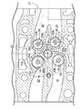
図1〜図7は本発明の実施の形態を示すもので、図1はディーゼルエンジンのシリンダヘッドの水平断面図(図3の1−1線断面図)、図2は図1の要部拡大図、図3は図1の3−3線断面図、図4は図1の4−4線断面図、図5は図1の5−5線断面図、図6は第1、第2吸気ポ−トの斜視図(図3の6方向矢視図)、図7は図6の7方向矢視図である。 1 to 7 show an embodiment of the present invention. FIG. 1 is a horizontal sectional view of a cylinder head of a diesel engine (a sectional view taken along line 1-1 in FIG. 3), and FIG. 2 is an enlarged view of a main part of FIG. 3 is a sectional view taken along line 3-3 in FIG. 1, FIG. 4 is a sectional view taken along line 4-4 in FIG. 1, FIG. 5 is a sectional view taken along line 5-5 in FIG. FIG. 7 is a perspective view of the port (seen in the direction of arrow 6 in FIG. 3), and FIG. 7 is a view in the direction of arrow 7 in FIG.
図1〜図5に示すように、直列4気筒のディーゼルエンジンは、シリンダブロック11に形成された4個のシリンダ11a…に摺動自在に嵌合する4個のピストン12…を備えており、各ピストン12の頂面にリエントラント型の燃焼室13が凹設される。シリンダブロック11の上面に結合されるシリンダヘッド14の下面に、各シリンダ11の頂面に対向する第1、第2吸気バルブ孔15,16と、第1、第2排気バルブ孔17,18とが開口しており、第1、第2吸気バルブ孔15,16に第1、第2吸気ポ−ト19,20が連通し、第1、第2排気バルブ孔17,18に第1、第2排気ポート21,22が連通する。
As shown in FIGS. 1 to 5, the in-line four-cylinder diesel engine includes four
4個のシリンダ11a…の中心を結ぶシリンダ列線L1に対して、第1、第2吸気ポ−ト19,20は一側に配置され、第1、第2排気ポート21,22は他側に配置される。第1、第2吸気ポ−ト19,20は各々独立してシリンダ列線L1に対して直交する方向に略直線状に延び、第1、第2排気ポート21,22は下流端が合流する。ピストン12が上死点にあるとき、ピストン12の上面とシリンダヘッド14の下面との間にスキッシュエリアが形成される。
The first and
第1、第2吸気バルブ23,24は、第1、第2吸気バルブ孔15,16を開閉するバルブボディ23a,24aと、バルブボディ23a,24aに連なるバルブステム23b,24bとを備えており、シリンダ軸線L2に対して平行に配置されたバルブステム23b,24bはバルブガイド25,25に摺動自在に支持され、吸気バルブスプリング26,26により閉弁方向に付勢される。一端が油圧タペット27に支持された吸気ロッカアーム28の他端が第1、第2吸気バルブ23,24のステムエンドに当接し、中間部に設けたローラ29が吸気カムシャフト30に設けた吸気カム31に当接する。
The first and
第1、第2排気バルブ32,33は、第1、第2排気バルブ孔17,18を開閉するバルブボディ32a,33aと、バルブボディ32a,33aに連なるバルブステム32b,33aとを備えており、シリンダ軸線L2に対して平行に配置されたバルブステム32b,33bはバルブガイド34,34に摺動自在に支持され、排気バルブスプリング35,35により閉弁方向に付勢される。一端が油圧タペット36に支持された排気ロッカアーム37の他端が第1、第2排気バルブ32,33のステムエンドに当接し、中間部に設けたローラ38が排気カムシャフト39に設けた排気カム40に当接する。
The first and
シリンダ軸線L2上に位置するインジェクタ41の先端と、シリンダ軸線L2に対して傾斜したグロープラグ42の先端とが燃焼室13に臨むように配置される。
The tip of the
しかして、吸気カムシャフト30が回転すると吸気カム31にローラ29を押圧された吸気ロッカアーム28が油圧タペット27を支点として揺動し、第1、第2吸気バルブ23,24のステムエンドを吸気バルブスプリング26,26の弾発力に抗して押圧することで開弁駆動する。また排気カムシャフト39が回転すると排気カム40にローラ38を押圧された排気ロッカアーム37が油圧タペット36を支点として揺動し、第1、第2排気バルブ32,33のステムエンドを排気バルブスプリング35,35の弾発力に抗して押圧することで開弁駆動する。
When the
図6および図7に示すように、第1吸気ポ−ト19は、第1吸気バルブ孔15の直上流のスロート部43が線状に延びるストレートポートであり、シリンダ軸線L2方向に見てシリンダ11a内周に対して接線方向に連なっている。従って、第1吸気バルブ23が開弁して第1吸気ポ−ト19からシリンダ11a内に吸気が導入されるとき、その吸気がシリンダ11a内周の接線方向に流れることでシリンダ軸線L2を囲むように第1スワールがS1が発生する。
As shown in FIGS. 6 and 7, the
第2吸気ポ−ト20は、第2吸気バルブ孔16の直上流のスロート部44が第2吸気バルブ24のバルブステム24bを囲むように螺旋状に延びるヘリカルポートである。スロート部44は、第2吸気バルブ孔16内周に接線方向に連なるように形成される螺旋外壁44aと、第2吸気バルブ24のバルブステム24bの径方向外側に形成される螺旋内壁44bとを備えており、旋回外壁44aおよび旋回内壁44bの壁間距離は吸気の流れ方向下流側ほど狭くなるように絞られている。これにより第2吸気ポ−ト20が発生する第2スワールS2が強められる反面、スロート部44おける吸気の流通抵抗が増加してしまう問題がある。
The
旋回外壁44aの上流側に連なる第1導入壁45はほぼ直線状に延びているが、この第1導入壁45に対向して旋回内壁44bに連なる第2導入壁46は、下流側ほど第1導入壁45に接近する方向に湾曲している。シリンダ軸線L2方向に見た第2吸気ポ−ト20の幅、つまり第1、第2導入壁45,46の壁間距離W(図2参照)は下流側ほど狭まっているため、吸気の流通抵抗は更に増加してしまう。しかしながら本実施の形態では、シリンダ軸線L2に直交する方向に見た第2吸気ポ−ト20の壁間距離H(図4参照)は下流側ほど広がっているため、第2吸気ポート20のスロート部44の狭まりと、その上流側の第2吸気ポート20の幅Wの狭まりとを、該第2吸気ポート20の高さHの広がりで補償し、絞りの強いヘリカルポートよりなる第2吸気ポート20の吸気の流通抵抗の増加を最小限に抑えることができる。
The
以上のように、シリンダ11aの内部に連なる第1、第2吸気ポート19,20のうち、ストレートポートよりなる第1吸気ポート19をシリンダ11a内周に接線方向に接続して第1スワールS1を発生させ、またヘリカルポートよりなる第2吸気ポート20により前記第1スワールS1の内側に該第1スワールS1と同方向の第2スワールS2を発生させるので、第1、第2スワールS1,S2の干渉を最小限に抑えて強いスワールを効果的に発生させることができる。しかも第1、第2吸気ポ−ト19,20をシリンダ列線L1に対して直交する方向に略直線的に配置しながら効率的にスワールS1,S2を発生させることができるので、シリンダヘッド14の加工コストの低減、シリンダヘッド14のコンパクト化、シリンダヘッド14の構造の簡素化が可能になる。
As described above, of the first and
特に、第1、第2吸気ポート19,20がシリンダ軸線L1に対して片側に配置されていて、シリンダ軸線L1の反対側(第1、第2排気ポート21,22側)に延びていないので、第1、第2吸気ポート19,20の長さを最小限に抑えることができ、これによりシリンダヘッド14の加工コストの更なる低減、シリンダヘッド14の更なるコンパクト化、シリンダヘッド14の構造の更なる簡素化が可能になる。
In particular, the first and
以上、本発明の実施の形態を説明したが、本発明はその要旨を逸脱しない範囲で種々の設計変更を行うことが可能である。 The embodiments of the present invention have been described above, but various design changes can be made without departing from the scope of the present invention.
例えば、実施の形態では直列4気筒のエンジンを例示したが、本発明は任意の気筒数のエンジンに対して適用することができる。尚、単気筒エンジンやV型2気筒エンジンの場合には、本発明の気筒列線方向L1とは、クランクシャフトと平行な方向として定義される。 For example, although an in-line four-cylinder engine has been exemplified in the embodiment, the present invention can be applied to an engine having an arbitrary number of cylinders. In the case of a single cylinder engine or a V-type two cylinder engine, the cylinder row direction L1 of the present invention is defined as a direction parallel to the crankshaft.
11a シリンダ
13 燃焼室
15 第1吸気バルブ孔
16 第2吸気バルブ孔
19 第1吸気ポート
20 第2吸気ポート
24b バルブステム
43 スロート部
44 スロート部
44a 螺旋外壁
44b 螺旋内壁
45 第1導入壁
46 第2導入壁
H 壁間距離
L1 シリンダ列線
S1 第1スワール
S2 第2スワール
W 壁間距離
Claims (2)
前記第1吸気ポ−ト(19)はスロート部(43)が直線状に形成されてシリンダ(11a)内周の接線方向に開口することで第1スワール(S1)を発生するストレートポートであり、前記第2吸気ポート(20)はスロート部(44)が螺旋状に形成されて前記第1スワール(S1)の内側に該第1スワール(S1)と同方向の第2スワール(S2)を発生するヘリカルポートであり、
前記第2吸気ポート(20)は、前記第2吸気バルブ孔(16)の周縁に沿って形成される螺旋外壁(44a)と、前記第2吸気バルブ孔(16)の中心に位置するバルブステム(24b)の径方向外側に形成される螺旋内壁(44b)と、前記螺旋外壁(44a)に連なって前記第2吸気バルブ孔(16)の接線方向に延びる第1導入壁(45)と、前記第1導入壁(45)と平行な状態から前記螺旋内壁(44b)に連続的に接続する第2導入壁(46)とを有し、吸気の流れ方向下流側に向かって第1、第2導入壁(45,46)の壁間距離(W)が減少するのに従って、前記第1、第2導入壁(45,46)の壁間距離(W)と直交する方向の壁間距離(H)が増加するように形成されることを特徴とするエンジンの吸気ポ−ト構造。 First and second intake valve holes (15, 16) opening first and second intake ports (19, 20) extending in a direction orthogonal to the cylinder row (L1) into the combustion chamber (13). ) In the intake port structure of the engine respectively connected to
The first intake port (19) is a straight port that generates the first swirl (S1) by opening the throat portion (43) in a straight line and opening in the tangential direction of the inner periphery of the cylinder (11a). The second intake port (20) has a throat portion (44) formed in a spiral shape, and a second swirl (S2) in the same direction as the first swirl (S1) is formed inside the first swirl (S1). Ri helical port der that occurs,
The second intake port (20) includes a spiral outer wall (44a) formed along the periphery of the second intake valve hole (16), and a valve stem positioned at the center of the second intake valve hole (16). A spiral inner wall (44b) formed on the radially outer side of (24b), a first introduction wall (45) extending in a tangential direction of the second intake valve hole (16) connected to the spiral outer wall (44a), A second introduction wall (46) continuously connected to the spiral inner wall (44b) from a state parallel to the first introduction wall (45), and the first and first 2 As the inter-wall distance (W) of the introduction wall (45, 46) decreases, the inter-wall distance (in the direction orthogonal to the inter-wall distance (W) of the first and second introduction walls (45, 46)) intake port of the engine, characterized in that H) is formed so as to increase - DOO structure
Priority Applications (6)
| Application Number | Priority Date | Filing Date | Title |
|---|---|---|---|
| JP2006132457A JP4680828B2 (en) | 2006-05-11 | 2006-05-11 | Engine intake port structure |
| MX2008013077A MX2008013077A (en) | 2006-05-11 | 2007-04-11 | Intake port structure for engine. |
| CA2645713A CA2645713C (en) | 2006-05-11 | 2007-04-11 | Intake port structure for engine |
| US12/296,480 US7707989B2 (en) | 2006-05-11 | 2007-04-11 | Intake port structure for engine |
| EP07741421A EP2017454A4 (en) | 2006-05-11 | 2007-04-11 | Intake port structure for engine |
| PCT/JP2007/057985 WO2007132606A1 (en) | 2006-05-11 | 2007-04-11 | Intake port structure for engine |
Applications Claiming Priority (1)
| Application Number | Priority Date | Filing Date | Title |
|---|---|---|---|
| JP2006132457A JP4680828B2 (en) | 2006-05-11 | 2006-05-11 | Engine intake port structure |
Publications (2)
| Publication Number | Publication Date |
|---|---|
| JP2007303365A JP2007303365A (en) | 2007-11-22 |
| JP4680828B2 true JP4680828B2 (en) | 2011-05-11 |
Family
ID=38693707
Family Applications (1)
| Application Number | Title | Priority Date | Filing Date |
|---|---|---|---|
| JP2006132457A Expired - Fee Related JP4680828B2 (en) | 2006-05-11 | 2006-05-11 | Engine intake port structure |
Country Status (6)
| Country | Link |
|---|---|
| US (1) | US7707989B2 (en) |
| EP (1) | EP2017454A4 (en) |
| JP (1) | JP4680828B2 (en) |
| CA (1) | CA2645713C (en) |
| MX (1) | MX2008013077A (en) |
| WO (1) | WO2007132606A1 (en) |
Families Citing this family (17)
| Publication number | Priority date | Publication date | Assignee | Title |
|---|---|---|---|---|
| JP4277857B2 (en) * | 2006-01-27 | 2009-06-10 | トヨタ自動車株式会社 | Intake port of internal combustion engine |
| EP2131025A1 (en) * | 2008-06-06 | 2009-12-09 | General Electric Company | Intake channels for internal combustion engines |
| US9194288B2 (en) | 2009-08-20 | 2015-11-24 | Pinnacle Engines, Inc. | High swirl engine |
| EP2497925B1 (en) * | 2009-11-05 | 2014-12-17 | Toyota Jidosha Kabushiki Kaisha | Intake apparatus of engine |
| AT508074B1 (en) * | 2010-03-18 | 2011-09-15 | Avl List Gmbh | CYLINDER HEAD |
| GB2484504B (en) * | 2010-10-12 | 2016-08-10 | Gm Global Tech Operations Llc | Two-duct intake port configuration for a combustion chamber of an internal combustion engine |
| KR101745005B1 (en) * | 2011-10-07 | 2017-06-09 | 현대자동차주식회사 | Diesel - Gasoline Complex Engine |
| WO2014104750A1 (en) * | 2012-12-26 | 2014-07-03 | 두산인프라코어 주식회사 | Engine intake port structure |
| US20170211508A1 (en) * | 2014-06-30 | 2017-07-27 | Cummins Inc. | System and method for valve size ratio and igniter placement |
| JP6410630B2 (en) * | 2015-02-17 | 2018-10-24 | 三菱重工エンジン&ターボチャージャ株式会社 | Cylinder head and engine |
| GB2553821B (en) * | 2016-09-15 | 2020-04-01 | Perkins Engines Co Ltd | Cylinder head with helical inlet passage |
| KR101826562B1 (en) * | 2016-11-02 | 2018-02-07 | 현대자동차 주식회사 | Apparatus for controlling gasolin-diesel complex combustion engine and method using the same |
| DE102017112350A1 (en) * | 2017-06-06 | 2018-12-06 | Dr. Ing. H.C. F. Porsche Aktiengesellschaft | Cylinder head for an internal combustion engine, internal combustion engine and method for operating an internal combustion engine |
| JP2019127884A (en) * | 2018-01-24 | 2019-08-01 | マツダ株式会社 | Engine cylinder head |
| GB2611102A (en) * | 2021-09-28 | 2023-03-29 | Jcb Res | Internal combustion engine |
| JP2023073137A (en) * | 2021-11-15 | 2023-05-25 | ヤマハ発動機株式会社 | Ship propulsion machine, ship and ship engine |
| CN117685127A (en) * | 2024-02-04 | 2024-03-12 | 潍柴动力股份有限公司 | Engine cylinder cover and engine |
Citations (5)
| Publication number | Priority date | Publication date | Assignee | Title |
|---|---|---|---|---|
| JPH0734884A (en) * | 1993-05-18 | 1995-02-03 | Mazda Motor Corp | Intake device for diesel engine |
| JPH07158459A (en) * | 1993-12-08 | 1995-06-20 | Toyota Motor Corp | Intake device for internal combustion engine |
| JPH09287461A (en) * | 1996-04-19 | 1997-11-04 | Toyota Motor Corp | Intake device for internal combustion engine |
| JPH1037751A (en) * | 1996-07-23 | 1998-02-10 | Toyota Motor Corp | Intake device for internal combustion engine |
| JP2002188451A (en) * | 2000-12-22 | 2002-07-05 | Toyota Industries Corp | Intake device for diesel engine |
Family Cites Families (20)
| Publication number | Priority date | Publication date | Assignee | Title |
|---|---|---|---|---|
| US2593769A (en) * | 1945-12-11 | 1952-04-22 | Kollsman Paul | Engine fuel injection |
| JPS5932647B2 (en) * | 1978-09-25 | 1984-08-10 | トヨタ自動車株式会社 | Helical intake port for internal combustion engines |
| JPS5920850B2 (en) * | 1978-09-25 | 1984-05-16 | トヨタ自動車株式会社 | Helical intake port for internal combustion engines |
| JPS6035539B2 (en) * | 1981-07-31 | 1985-08-15 | トヨタ自動車株式会社 | Flow path control device for helical intake port |
| JPH0652057B2 (en) * | 1984-05-07 | 1994-07-06 | トヨタ自動車株式会社 | Internal combustion engine controller |
| JPH0646021B2 (en) * | 1984-05-07 | 1994-06-15 | トヨタ自動車株式会社 | Ignition timing control device for internal combustion engine |
| US4834035A (en) * | 1985-08-23 | 1989-05-30 | Mitsubishi Jidosha Kogyo Kabushiki Kaisha | Variable swirl intake apparatus for engine |
| EP0619424B1 (en) * | 1993-04-05 | 1997-03-05 | Isuzu Motors Limited | Multi-intake valve engine |
| US5435283A (en) * | 1994-01-07 | 1995-07-25 | Cummins Engine Company, Inc. | Swirl control system for varying in-cylinder swirl |
| US5558061A (en) * | 1995-12-22 | 1996-09-24 | General Motors Corporation | Engine cylinder intake port |
| US6003485A (en) * | 1997-06-10 | 1999-12-21 | Nissan Motor Co., Ltd. | Helical intake port for an internal combustion engine |
| JP4022006B2 (en) * | 1998-06-09 | 2007-12-12 | ヤンマー株式会社 | Intake port shape of internal combustion engine |
| JP3523529B2 (en) * | 1999-06-15 | 2004-04-26 | 株式会社クボタ | Direct intake port and helical intake port of engine |
| JP3807207B2 (en) * | 1999-12-24 | 2006-08-09 | いすゞ自動車株式会社 | Multi-valve intake engine |
| WO2001055567A1 (en) * | 2000-01-25 | 2001-08-02 | Kabushiki Kaisha Toyota Chuo Kenkyusho | Direct injection type internal combustion engine |
| JP3821351B2 (en) * | 2000-05-31 | 2006-09-13 | スズキ株式会社 | Intake device for multi-cylinder internal combustion engine |
| US6553959B2 (en) * | 2000-06-13 | 2003-04-29 | Visteon Global Technologies, Inc. | Electronic flow control for a stratified EGR system |
| AT5487U1 (en) * | 2001-01-29 | 2002-07-25 | Avl List Gmbh | INLET CHANNEL ARRANGEMENT FOR AN INTERNAL COMBUSTION ENGINE |
| JP4356329B2 (en) * | 2002-03-11 | 2009-11-04 | トヨタ自動車株式会社 | Intake port of internal combustion engine |
| JP2004052636A (en) * | 2002-07-18 | 2004-02-19 | Hitachi Ltd | Starting device, starting method, control method and exhaust emission control device for internal combustion engine |
-
2006
- 2006-05-11 JP JP2006132457A patent/JP4680828B2/en not_active Expired - Fee Related
-
2007
- 2007-04-11 EP EP07741421A patent/EP2017454A4/en not_active Withdrawn
- 2007-04-11 CA CA2645713A patent/CA2645713C/en not_active Expired - Fee Related
- 2007-04-11 MX MX2008013077A patent/MX2008013077A/en active IP Right Grant
- 2007-04-11 US US12/296,480 patent/US7707989B2/en not_active Expired - Fee Related
- 2007-04-11 WO PCT/JP2007/057985 patent/WO2007132606A1/en active Application Filing
Patent Citations (5)
| Publication number | Priority date | Publication date | Assignee | Title |
|---|---|---|---|---|
| JPH0734884A (en) * | 1993-05-18 | 1995-02-03 | Mazda Motor Corp | Intake device for diesel engine |
| JPH07158459A (en) * | 1993-12-08 | 1995-06-20 | Toyota Motor Corp | Intake device for internal combustion engine |
| JPH09287461A (en) * | 1996-04-19 | 1997-11-04 | Toyota Motor Corp | Intake device for internal combustion engine |
| JPH1037751A (en) * | 1996-07-23 | 1998-02-10 | Toyota Motor Corp | Intake device for internal combustion engine |
| JP2002188451A (en) * | 2000-12-22 | 2002-07-05 | Toyota Industries Corp | Intake device for diesel engine |
Also Published As
| Publication number | Publication date |
|---|---|
| EP2017454A4 (en) | 2011-11-16 |
| WO2007132606A1 (en) | 2007-11-22 |
| MX2008013077A (en) | 2008-12-16 |
| US20090159041A1 (en) | 2009-06-25 |
| EP2017454A1 (en) | 2009-01-21 |
| CA2645713A1 (en) | 2007-11-22 |
| JP2007303365A (en) | 2007-11-22 |
| CA2645713C (en) | 2011-05-24 |
| US7707989B2 (en) | 2010-05-04 |
Similar Documents
| Publication | Publication Date | Title |
|---|---|---|
| JP4680828B2 (en) | Engine intake port structure | |
| EP1979590A2 (en) | Internal combustion engine | |
| JP3494284B2 (en) | Intake port structure of 4-stroke cycle internal combustion engine | |
| JP6115197B2 (en) | Combustion chamber structure of internal combustion engine | |
| JP4290147B2 (en) | Internal combustion engine | |
| WO2018074205A1 (en) | Thermally insulated insert member and engine provided with same | |
| JP4876022B2 (en) | Internal combustion engine | |
| KR100820700B1 (en) | Exhaust system | |
| JP6055709B2 (en) | Intake device for internal combustion engine | |
| JP3526836B2 (en) | Locking device for rocker arm shaft in valve train of internal combustion engine | |
| JP3848526B2 (en) | Engine fuel injection valve arrangement structure | |
| JPH08189366A (en) | Intake port structure for internal combustion engine | |
| JP2709261B2 (en) | 4 cycle engine | |
| JP6241988B2 (en) | Internal combustion engine | |
| JP6524727B2 (en) | Engine intake port structure | |
| JP2008038841A (en) | Injector seal member | |
| EP3667033A1 (en) | Clyinder head | |
| JP4561444B2 (en) | V-type 6-cylinder 4-cycle engine intake system | |
| KR20090064806A (en) | Variable valve system | |
| JP3329405B2 (en) | Intake control structure for two-valve engine | |
| JP4198037B2 (en) | Internal combustion engine | |
| WO2007080603A3 (en) | Rocker arm assembly for an internal combustion engine | |
| JP2021017828A (en) | Valve structure and internal combustion engine | |
| JPH0643461Y2 (en) | V-type engine intake device | |
| JP2020133448A (en) | Intake device of engine |
Legal Events
| Date | Code | Title | Description |
|---|---|---|---|
| A621 | Written request for application examination |
Free format text: JAPANESE INTERMEDIATE CODE: A621 Effective date: 20081127 |
|
| A131 | Notification of reasons for refusal |
Free format text: JAPANESE INTERMEDIATE CODE: A131 Effective date: 20101027 |
|
| A521 | Request for written amendment filed |
Free format text: JAPANESE INTERMEDIATE CODE: A523 Effective date: 20101213 |
|
| TRDD | Decision of grant or rejection written | ||
| A01 | Written decision to grant a patent or to grant a registration (utility model) |
Free format text: JAPANESE INTERMEDIATE CODE: A01 Effective date: 20110126 |
|
| A01 | Written decision to grant a patent or to grant a registration (utility model) |
Free format text: JAPANESE INTERMEDIATE CODE: A01 |
|
| A61 | First payment of annual fees (during grant procedure) |
Free format text: JAPANESE INTERMEDIATE CODE: A61 Effective date: 20110203 |
|
| R150 | Certificate of patent or registration of utility model |
Free format text: JAPANESE INTERMEDIATE CODE: R150 |
|
| FPAY | Renewal fee payment (event date is renewal date of database) |
Free format text: PAYMENT UNTIL: 20140210 Year of fee payment: 3 |
|
| LAPS | Cancellation because of no payment of annual fees |