EP2940263B1 - Automatic regeneration control device for particulate filter - Google Patents
Automatic regeneration control device for particulate filter Download PDFInfo
- Publication number
- EP2940263B1 EP2940263B1 EP13869791.7A EP13869791A EP2940263B1 EP 2940263 B1 EP2940263 B1 EP 2940263B1 EP 13869791 A EP13869791 A EP 13869791A EP 2940263 B1 EP2940263 B1 EP 2940263B1
- Authority
- EP
- European Patent Office
- Prior art keywords
- load
- particulate filter
- controller
- load application
- regeneration
- Prior art date
- Legal status (The legal status is an assumption and is not a legal conclusion. Google has not performed a legal analysis and makes no representation as to the accuracy of the status listed.)
- Not-in-force
Links
Images


Classifications
-
- F—MECHANICAL ENGINEERING; LIGHTING; HEATING; WEAPONS; BLASTING
- F02—COMBUSTION ENGINES; HOT-GAS OR COMBUSTION-PRODUCT ENGINE PLANTS
- F02D—CONTROLLING COMBUSTION ENGINES
- F02D41/00—Electrical control of supply of combustible mixture or its constituents
- F02D41/02—Circuit arrangements for generating control signals
- F02D41/021—Introducing corrections for particular conditions exterior to the engine
- F02D41/0235—Introducing corrections for particular conditions exterior to the engine in relation with the state of the exhaust gas treating apparatus
- F02D41/027—Introducing corrections for particular conditions exterior to the engine in relation with the state of the exhaust gas treating apparatus to purge or regenerate the exhaust gas treating apparatus
- F02D41/029—Introducing corrections for particular conditions exterior to the engine in relation with the state of the exhaust gas treating apparatus to purge or regenerate the exhaust gas treating apparatus the exhaust gas treating apparatus being a particulate filter
-
- F—MECHANICAL ENGINEERING; LIGHTING; HEATING; WEAPONS; BLASTING
- F01—MACHINES OR ENGINES IN GENERAL; ENGINE PLANTS IN GENERAL; STEAM ENGINES
- F01N—GAS-FLOW SILENCERS OR EXHAUST APPARATUS FOR MACHINES OR ENGINES IN GENERAL; GAS-FLOW SILENCERS OR EXHAUST APPARATUS FOR INTERNAL COMBUSTION ENGINES
- F01N3/00—Exhaust or silencing apparatus having means for purifying, rendering innocuous, or otherwise treating exhaust
- F01N3/02—Exhaust or silencing apparatus having means for purifying, rendering innocuous, or otherwise treating exhaust for cooling, or for removing solid constituents of, exhaust
- F01N3/021—Exhaust or silencing apparatus having means for purifying, rendering innocuous, or otherwise treating exhaust for cooling, or for removing solid constituents of, exhaust by means of filters
- F01N3/023—Exhaust or silencing apparatus having means for purifying, rendering innocuous, or otherwise treating exhaust for cooling, or for removing solid constituents of, exhaust by means of filters using means for regenerating the filters, e.g. by burning trapped particles
- F01N3/025—Exhaust or silencing apparatus having means for purifying, rendering innocuous, or otherwise treating exhaust for cooling, or for removing solid constituents of, exhaust by means of filters using means for regenerating the filters, e.g. by burning trapped particles using fuel burner or by adding fuel to exhaust
- F01N3/0253—Exhaust or silencing apparatus having means for purifying, rendering innocuous, or otherwise treating exhaust for cooling, or for removing solid constituents of, exhaust by means of filters using means for regenerating the filters, e.g. by burning trapped particles using fuel burner or by adding fuel to exhaust adding fuel to exhaust gases
-
- B—PERFORMING OPERATIONS; TRANSPORTING
- B01—PHYSICAL OR CHEMICAL PROCESSES OR APPARATUS IN GENERAL
- B01D—SEPARATION
- B01D46/00—Filters or filtering processes specially modified for separating dispersed particles from gases or vapours
- B01D46/66—Regeneration of the filtering material or filter elements inside the filter
- B01D46/80—Chemical processes for the removal of the retained particles, e.g. by burning
- B01D46/82—Chemical processes for the removal of the retained particles, e.g. by burning with catalysts
-
- F—MECHANICAL ENGINEERING; LIGHTING; HEATING; WEAPONS; BLASTING
- F01—MACHINES OR ENGINES IN GENERAL; ENGINE PLANTS IN GENERAL; STEAM ENGINES
- F01N—GAS-FLOW SILENCERS OR EXHAUST APPARATUS FOR MACHINES OR ENGINES IN GENERAL; GAS-FLOW SILENCERS OR EXHAUST APPARATUS FOR INTERNAL COMBUSTION ENGINES
- F01N3/00—Exhaust or silencing apparatus having means for purifying, rendering innocuous, or otherwise treating exhaust
- F01N3/08—Exhaust or silencing apparatus having means for purifying, rendering innocuous, or otherwise treating exhaust for rendering innocuous
- F01N3/10—Exhaust or silencing apparatus having means for purifying, rendering innocuous, or otherwise treating exhaust for rendering innocuous by thermal or catalytic conversion of noxious components of exhaust
- F01N3/105—General auxiliary catalysts, e.g. upstream or downstream of the main catalyst
- F01N3/106—Auxiliary oxidation catalysts
-
- F—MECHANICAL ENGINEERING; LIGHTING; HEATING; WEAPONS; BLASTING
- F01—MACHINES OR ENGINES IN GENERAL; ENGINE PLANTS IN GENERAL; STEAM ENGINES
- F01N—GAS-FLOW SILENCERS OR EXHAUST APPARATUS FOR MACHINES OR ENGINES IN GENERAL; GAS-FLOW SILENCERS OR EXHAUST APPARATUS FOR INTERNAL COMBUSTION ENGINES
- F01N9/00—Electrical control of exhaust gas treating apparatus
- F01N9/002—Electrical control of exhaust gas treating apparatus of filter regeneration, e.g. detection of clogging
-
- F—MECHANICAL ENGINEERING; LIGHTING; HEATING; WEAPONS; BLASTING
- F02—COMBUSTION ENGINES; HOT-GAS OR COMBUSTION-PRODUCT ENGINE PLANTS
- F02D—CONTROLLING COMBUSTION ENGINES
- F02D29/00—Controlling engines, such controlling being peculiar to the devices driven thereby, the devices being other than parts or accessories essential to engine operation, e.g. controlling of engines by signals external thereto
- F02D29/04—Controlling engines, such controlling being peculiar to the devices driven thereby, the devices being other than parts or accessories essential to engine operation, e.g. controlling of engines by signals external thereto peculiar to engines driving pumps
-
- F—MECHANICAL ENGINEERING; LIGHTING; HEATING; WEAPONS; BLASTING
- F01—MACHINES OR ENGINES IN GENERAL; ENGINE PLANTS IN GENERAL; STEAM ENGINES
- F01N—GAS-FLOW SILENCERS OR EXHAUST APPARATUS FOR MACHINES OR ENGINES IN GENERAL; GAS-FLOW SILENCERS OR EXHAUST APPARATUS FOR INTERNAL COMBUSTION ENGINES
- F01N13/00—Exhaust or silencing apparatus characterised by constructional features ; Exhaust or silencing apparatus, or parts thereof, having pertinent characteristics not provided for in, or of interest apart from, groups F01N1/00 - F01N5/00, F01N9/00, F01N11/00
- F01N13/009—Exhaust or silencing apparatus characterised by constructional features ; Exhaust or silencing apparatus, or parts thereof, having pertinent characteristics not provided for in, or of interest apart from, groups F01N1/00 - F01N5/00, F01N9/00, F01N11/00 having two or more separate purifying devices arranged in series
- F01N13/0097—Exhaust or silencing apparatus characterised by constructional features ; Exhaust or silencing apparatus, or parts thereof, having pertinent characteristics not provided for in, or of interest apart from, groups F01N1/00 - F01N5/00, F01N9/00, F01N11/00 having two or more separate purifying devices arranged in series the purifying devices are arranged in a single housing
-
- F—MECHANICAL ENGINEERING; LIGHTING; HEATING; WEAPONS; BLASTING
- F01—MACHINES OR ENGINES IN GENERAL; ENGINE PLANTS IN GENERAL; STEAM ENGINES
- F01N—GAS-FLOW SILENCERS OR EXHAUST APPARATUS FOR MACHINES OR ENGINES IN GENERAL; GAS-FLOW SILENCERS OR EXHAUST APPARATUS FOR INTERNAL COMBUSTION ENGINES
- F01N2430/00—Influencing exhaust purification, e.g. starting of catalytic reaction, filter regeneration, or the like, by controlling engine operating characteristics
- F01N2430/08—Influencing exhaust purification, e.g. starting of catalytic reaction, filter regeneration, or the like, by controlling engine operating characteristics by modifying ignition or injection timing
- F01N2430/085—Influencing exhaust purification, e.g. starting of catalytic reaction, filter regeneration, or the like, by controlling engine operating characteristics by modifying ignition or injection timing at least a part of the injection taking place during expansion or exhaust stroke
-
- F—MECHANICAL ENGINEERING; LIGHTING; HEATING; WEAPONS; BLASTING
- F01—MACHINES OR ENGINES IN GENERAL; ENGINE PLANTS IN GENERAL; STEAM ENGINES
- F01N—GAS-FLOW SILENCERS OR EXHAUST APPARATUS FOR MACHINES OR ENGINES IN GENERAL; GAS-FLOW SILENCERS OR EXHAUST APPARATUS FOR INTERNAL COMBUSTION ENGINES
- F01N2590/00—Exhaust or silencing apparatus adapted to particular use, e.g. for military applications, airplanes, submarines
- F01N2590/08—Exhaust or silencing apparatus adapted to particular use, e.g. for military applications, airplanes, submarines for heavy duty applications, e.g. trucks, buses, tractors, locomotives
-
- F—MECHANICAL ENGINEERING; LIGHTING; HEATING; WEAPONS; BLASTING
- F01—MACHINES OR ENGINES IN GENERAL; ENGINE PLANTS IN GENERAL; STEAM ENGINES
- F01N—GAS-FLOW SILENCERS OR EXHAUST APPARATUS FOR MACHINES OR ENGINES IN GENERAL; GAS-FLOW SILENCERS OR EXHAUST APPARATUS FOR INTERNAL COMBUSTION ENGINES
- F01N2590/00—Exhaust or silencing apparatus adapted to particular use, e.g. for military applications, airplanes, submarines
- F01N2590/10—Exhaust or silencing apparatus adapted to particular use, e.g. for military applications, airplanes, submarines for stationary applications
-
- F—MECHANICAL ENGINEERING; LIGHTING; HEATING; WEAPONS; BLASTING
- F01—MACHINES OR ENGINES IN GENERAL; ENGINE PLANTS IN GENERAL; STEAM ENGINES
- F01N—GAS-FLOW SILENCERS OR EXHAUST APPARATUS FOR MACHINES OR ENGINES IN GENERAL; GAS-FLOW SILENCERS OR EXHAUST APPARATUS FOR INTERNAL COMBUSTION ENGINES
- F01N2900/00—Details of electrical control or of the monitoring of the exhaust gas treating apparatus
- F01N2900/06—Parameters used for exhaust control or diagnosing
- F01N2900/14—Parameters used for exhaust control or diagnosing said parameters being related to the exhaust gas
- F01N2900/1404—Exhaust gas temperature
-
- F—MECHANICAL ENGINEERING; LIGHTING; HEATING; WEAPONS; BLASTING
- F02—COMBUSTION ENGINES; HOT-GAS OR COMBUSTION-PRODUCT ENGINE PLANTS
- F02D—CONTROLLING COMBUSTION ENGINES
- F02D41/00—Electrical control of supply of combustible mixture or its constituents
- F02D41/02—Circuit arrangements for generating control signals
- F02D41/021—Introducing corrections for particular conditions exterior to the engine
- F02D41/0235—Introducing corrections for particular conditions exterior to the engine in relation with the state of the exhaust gas treating apparatus
- F02D41/024—Introducing corrections for particular conditions exterior to the engine in relation with the state of the exhaust gas treating apparatus to increase temperature of the exhaust gas treating apparatus
- F02D2041/026—Introducing corrections for particular conditions exterior to the engine in relation with the state of the exhaust gas treating apparatus to increase temperature of the exhaust gas treating apparatus using an external load, e.g. by increasing generator load or by changing the gear ratio
-
- F—MECHANICAL ENGINEERING; LIGHTING; HEATING; WEAPONS; BLASTING
- F02—COMBUSTION ENGINES; HOT-GAS OR COMBUSTION-PRODUCT ENGINE PLANTS
- F02D—CONTROLLING COMBUSTION ENGINES
- F02D2200/00—Input parameters for engine control
- F02D2200/02—Input parameters for engine control the parameters being related to the engine
- F02D2200/08—Exhaust gas treatment apparatus parameters
- F02D2200/0812—Particle filter loading
-
- Y—GENERAL TAGGING OF NEW TECHNOLOGICAL DEVELOPMENTS; GENERAL TAGGING OF CROSS-SECTIONAL TECHNOLOGIES SPANNING OVER SEVERAL SECTIONS OF THE IPC; TECHNICAL SUBJECTS COVERED BY FORMER USPC CROSS-REFERENCE ART COLLECTIONS [XRACs] AND DIGESTS
- Y02—TECHNOLOGIES OR APPLICATIONS FOR MITIGATION OR ADAPTATION AGAINST CLIMATE CHANGE
- Y02T—CLIMATE CHANGE MITIGATION TECHNOLOGIES RELATED TO TRANSPORTATION
- Y02T10/00—Road transport of goods or passengers
- Y02T10/10—Internal combustion engine [ICE] based vehicles
- Y02T10/40—Engine management systems
Definitions
- the present invention relates to an automatic regeneration controller for a particulate filter.
- particulates (particulate matter) from a diesel engine in an automobile is mainly constituted by carbonic soot and a soluble organic fraction (SOF) of high-boiling hydrocarbon and contains a trace of sulfate (misty sulfuric acid fraction).
- SOF soluble organic fraction
- sulfate molecular sulfuric acid fraction
- Such kind of particulate filter has a porous honeycomb structure made of ceramics such as cordierite and having lattice-like compartmentalized passages; alternate ones of the passages have plugged inlets and the remaining passages with unplugged open inlets have plugged outlets. Thus, only the exhaust gas passing through thin porous walls compartmentalizing the passages is discharged downstream.
- the particulates in the exhaust gas which are captured and accumulated on inner surfaces of the thin porous walls, require to be burned off for regeneration of the particulate filter before exhaust resistance increases due to clogging.
- exhaust gas from a normal engine in an automobile rarely has a chance to reach a temperature level at which the particulates ignite by themselves, so that employed is a catalyst-regenerative particulate filter integrally carrying an oxidation catalyst.
- the catalyst-regenerative particulate filter facilitates an oxidation reaction of the particulates captured to lower an ignition temperature, so that the particulates may be burned off even at an exhaust temperature level lower than ever before.
- a captured amount may exceed a treatment amount of the particulates in an operation area having a lower exhaust temperature level. Continued operation at such lower exhaust temperature level may hinder sufficient regeneration of the particulate filter, possibly resulting in excessive accumulation of the captured particulates in the particulate filter.
- a flow-through oxidation catalyst is additionally arranged on an entry side of the particulate filter; with the accumulation of the particulates becoming increased, fuel is added to the exhaust gas upstream of the particular filter to regenerate the particulate filter.
- the addition of the fuel upstream of the particulate filter in post injection or the like generates HC gas which causes an oxidation reaction on the oxidation catalyst of the particulate filter. Heat of the reaction increases a bed temperature of the catalyst to burn off the particulates, thereby regenerating the particulate filter.
- Specific measure for such fuel addition may be such that main injection of the fuel near a compression top dead center is followed by post injection at non-ignition timing after the top dead center to add the fuel into the exhaust gas.
- an accumulation amount of the particulates is estimated on the basis of, for example, a cumulative amount of a difference between estimated generation and treatment amounts of particulates calculated from a difference of pressures before and after the particulate filter, an engine rotation frequency and a load, and regeneration of the particulate filter is automatically conducted when the estimated value exceeds a set value.
- the regeneration of the particulate filter may be not always completed depending on an intermittent situation of the work; repetition of such situations may increase the accumulation amount of the particulates in the particulate filter.
- a technique has been suggested that a temperature of the exhaust gas is increased by increasing an idling rotation frequency during idling while an exhaust brake or an intake valve is closed.
- parts such as the exhaust brake and the intake valve are not installed unlike the case of the automobile; to newly provide these parts only for regeneration of the particulate filter would result in substantial increase in cost.
- Patent Literature 1 a technique of effectively regenerating at low cost a particulate filter arranged in an industrial engine such as that mounted on a constructing machine or the like for driving a hydraulic or other work unit using engine power to conduct various works.
- JP 2009-191654A discloses that for regeneration of the particulate filter, forced load application to the work unit intentionally increases an engine load, and a post injection or other fuel addition is conducted with the exhaust temperature being increased by the increased load.
- US 2012/260633 A1 discloses that a step of determining whether or not a particulate filter abnormal combustion causing operation has occurred. Such an abnormal combustion causing operation occurs when the internal combustion engine shifts from a high to a low load operation condition.
- the invention was made in view of the above and has its object to provide an automatic regeneration controller for a particulate filter which can stop forced load application to a work unit depending on a situation of the work unit to thereby smooth the work and which can stop the regeneration of the particulate filter when the exhaust temperature cannot be maintained to be high upon the stoppage of the load application during automatic regeneration control of the particulate filter, thereby preventing deteriorated fuel economy and generation of white smoke.
- the invention is directed to an automatic regeneration controller for a particulate filter wherein an oxidation catalyst and the particulate filter are sequentially arranged in an exhaust pipe of an industrial engine for driving a work unit using engine power to conduct various works, fuel being added to the exhaust gas upstream of the oxidation catalyst with a load being forcedly applied to said work unit to intently increase an engine load and increase an exhaust temperature by said increased load, said added fuel undergoing oxidation reaction on the oxidation catalyst and resultant reaction heat burning captured particulates in the particulate filter just behind to thereby conduct regeneration of said particulate filter, comprising an engine controller for outputting a fuel injection signal to said industrial engine when an estimated accumulation amount of said particulates is determined to exceed a set value, a unit controller for outputting a unit control signal to said hydraulic unit for collaborative control thereof, collaborative control signals being mutually inputted and outputted between said unit and engine controllers and a load application cancelation switch for outputting a cancellation signal to said unit controller depending upon a situation of said work unit to stop the forced load application
- the automatic regeneration controller for the particulate filter may be configured such that, with the regeneration of the particulate filter being started by determination of captured particulate accumulation, with the idling or light-load operation being conducted, and with load request to said work unit being outputted from said engine controller to said unit controller, when the load application is not possible or the load application cancelation switch is on and, in addition, maintaining the exhaust temperature with no load application is possible, then the fuel addition is conducted and the automatic regeneration control is continued with no forced load application to said work unit.
- the automatic regeneration controller for the particulate filter may be configured such that, with regeneration of the particulate filter being started by determination of captured particulate accumulation, with the idling or light-load operation being conducted, and with load request to said work unit being outputted from said engine controller to said unit controller, when the load application is possible and the load application cancelation switch is off, then the fuel addition is conducted and the automatic regeneration control is continued with the forced load application to said work unit being conducted to intentionally increase the engine load and increase the exhaust temperature by said increased load.
- the automatic regeneration controller for the particulate filter may be configured such that, with regeneration of the particulate filter being started by determination of captured particulate accumulation and with no idling or light-load operation being conducted, the fuel addition is conducted and the automatic regeneration control is continued with no forced load application to said work unit.
- An automatic regeneration controller for a particulate filter according to the invention can exhibit excellent effects that forced load application to a work unit can be stopped depending upon a situation of the work unit to thereby smooth the work and that regeneration of a particulate filter can be stopped when an exhaust temperature cannot be maintained to be high upon the stoppage of the load application during automatic regeneration control of the particulate filter, thereby preventing deteriorated fuel economy and generation of white smoke.
- Figs. 1-3 show the embodiment of an automatic regeneration controller for a particulate filter according to the invention.
- Reference numeral 1 denotes an industrial engine mounted on a crane, a shovel or other constructing machine; and 2, a hydraulic unit as work unit driven by the industrial engine 1.
- Exhaust gas 3 discharged from the industrial engine 1 flows through an exhaust pipe 4 in which incorporated is a filter case 5.
- Contained in the filter case 5 on a downstream side is a particulate filter 6 for capture of particulates in the exhaust gas 3; and contained in the filter case 5 on an upstream side is an oxidation catalyst 7 for oxidation treatment of unburned HC gas in the exhaust gas 3.
- Fuel injection control in the industrial engine 1 is conducted on the basis of a fuel injection signal 8a outputted from an engine controller 8.
- an accumulation amount of the particulates is estimated on the basis of, for example, a cumulative amount of a difference between estimated production and treatment amounts of the particulates calculated from a difference in pressure before and after the particulate filter 6, an engine rotation frequency and a load.
- a fuel injection signal 8a is outputted to conduct post injection at non-ignition timing after the compression top dead center following main injection of the fuel near the compression top dead center (crank angle 0°).
- the post injection at the non-ignition timing after the compression top dead center following the main injection adds unburned fuel into the exhaust gas 3, so that the unburned fuel generates HC gas with high concentration which is directed to the entry-side oxidation catalyst 7.
- collaborative control signals 10 are mutually inputted and outputted between the engine and unit controllers 8 and 9 for control of the hydraulic unit 2 as the work unit, so that the hydraulic unit 2 is collaboratively controlled by a unit control signal 9a outputted from the unit controller 9.
- a hydraulic pump is driven to circulate an operating oil to thereby conduct a load application operation in the hydraulic unit 2.
- a load application cancelation switch 11 is provided to output, to the unit controller 9, a cancellation signal 11a for stoppage of the forced load application to the hydraulic unit 2 depending on a situation of the hydraulic unit 2.
- the load application cancelation switch 11 can be operated by an operator as needs demand.
- the embodiment is configured, as shown in the flowchart of Figs. 2 and 3 , such that when the regeneration of the particulate filter 6 is started by determination in the engine controller 8 of captured particulate accumulation (see step S1), firstly made is determination on whether an idling or light-load operation is conducted or not (see step S2); if the idling or light-load operation being conducted is determined, load request to the hydraulic unit 2 as the work unit is outputted from the engine controller 8 to the unit controller 9 (see step S3).
- step S4 determines whether load application is possible or not (see step S4) is negative or when determination made on whether the load application cancelation switch 11 is off or not (see step S5) is negative, made is determination on whether exhaust temperature is maintainable or not with no load application (see step S6); if the exhaust temperature not maintainable with no load application is determined, then a regeneration stop signal is outputted from the unit controller 9 to the engine controller 8 (see step S7) and a regeneration stop signal reception process is conducted in the engine controller 8 (see step S8), and with no forced load application to the hydraulic unit 2 (see step S9), the post injection or other fuel addition is stopped to stop the automatic regeneration control (see step S10).
- the procedure is returned to the above-mentioned step S2 to determine whether the idling or light-load operation is conducted or not, and controls with determinations similar to those mentioned in the above are repeated.
- the configuration is further such that when the determination in the above-mentioned step S6 made on whether the exhaust temperature is maintainable or not with no load application is affirmative, then with no forced load application to the hydraulic unit 2 as the work unit (see step S11), the post injection or other fuel addition is conducted to continue the automatic regeneration control (see step S12).
- the automatic regeneration control being continued in the above-mentioned step S12, if determination made on whether the regeneration of the particulate filter 6 is completed or not (see step S13) is affirmative, the regeneration is ended; if negative, the procedure is returned to the above-mentioned step S2 to determine whether the idling or light-load operation is conducted or not, and controls with determinations similar to those mentioned in the above are repeated.
- the configuration is such that, when the determination made in the above-mentioned step S4 on whether load application is possible or not is affirmative and the determination made in the above-mentioned step S5 on whether load application cancelation switch 11 is off or not is affirmative, then with the forced load application to the hydraulic unit 2 as the work unit being conducted (see step S14) to intentionally increase the engine load and increase the exhaust temperature by the increased load, the post injection or other fuel addition is conducted to continue the automatic regeneration control (see step S15).
- step S15 if determination made on whether the regeneration of the particulate filter 6 is completed or not (see step S13) is affirmative, the regeneration is ended; if negative, the procedure is returned to the above-mentioned step S2 to determine whether the idling or light-load operation is conducted or not, and controls with determinations similar to those mentioned in the above are repeated.
- the configuration is such that, when the determination made in the above-mentioned step 2 on whether the idling or light-load operation is conducted or not is negative, the load has been already applied, so that with no forced load application to the hydraulic unit 2 as the work unit (see step S11), the post injection or other fuel addition is conducted to continue the automatic regeneration control (see step S12).
- step S1 When the regeneration of the particulate filter 6 is started by determination of captured particulate accumulation in the engine controller 8 (see step S1), firstly made is the determination on whether the idling or light-load operation is conducted or not (see step S2); if the idling or light-load operation being conducted is determined, load request to the hydraulic unit 2 as the work unit is outputted from the engine controller 8 to the unit controller 9 (see step S3).
- step S4 determines whether the load application is possible or not (see step S4) is negative or the determination made on whether the load application cancelation switch 11 is off or not (see step S5) is negative, then made is the determination on whether the exhaust temperature is maintainable or not with no load application (see step S6); if the exhaust temperature not maintainable with no load application is determined, then the regeneration stop signal is outputted from the unit controller 9 to the engine controller 8 (see step S7) and the regeneration stop signal reception process is conducted in the engine controller 8 (see step S8), and with no forced load application to the hydraulic unit 2 (see step S9), the post injection or other fuel addition is stopped to stop the automatic regeneration control (see step S10).
- the procedure is returned to the above-mentioned step S2 to determine whether the idling or light-load operation is conducted or not, and controls with determinations similar to those mentioned in the above are repeated.
- step S6 When the determination in the above-mentioned step S6 made on whether exhaust temperature is maintainable with no load application is affirmative, then with no forced load application to the hydraulic unit 2 as the work unit (see step S11), the post injection or other fuel addition is conducted to continue the automatic regeneration control (see step S12).
- a load on the hydraulic unit 2 during a work is relatively great and an engine torque is high, so that, with the automatic regeneration control being conducted on the engine side and with the post injection or other fuel addition being conducted, the exhaust temperature can be maintained to be high even if an operator determines to turn on the load application cancelation switch 11 to stop the load application.
- step S12 With the automatic regeneration control being continued in the above-mentioned step S12, if the determination made on whether the regeneration of the particulate filter 6 is completed or not (see step S13) is affirmative, the regeneration is ended; if negative, the procedure is returned to the above-mentioned step S2 to determine whether the idling or light-load operation is conducted or not, and controls with determinations similar to those mentioned in the above are repeated.
- step S4 when the determination made in the above-mentioned step S4 on whether load application is possible or not is affirmative and the determination made in the above-mentioned step S5 on whether the load application cancelation switch 11 is off or not is affirmative, then with the forced load application to the hydraulic unit 2 as the work unit being conducted (see step S14) to intentionally increase the engine load and increase the exhaust temperature by the increased load, the post injection or other fuel addition is conducted to continue the automatic regeneration control (see step S15).
- step S15 if the determination made on whether the regeneration of the particulate filter 6 is completed or not (see step S13) is affirmative, the regeneration of the particulate filter 6 is ended; if negative, the procedure is returned to the above-mentioned step S2 to determine whether the idling or light-load operation is conducted or not, and controls with determinations similar to those mentioned in the above are repeated.
- step S2 When the determination made in the above-mentioned step S2 on whether the idling or light-load operation is conducted or not is negative, the load has been already applied, so that with no forced load application to the hydraulic unit 2 as the work unit (see step S11), the post injection or other fuel addition is conducted to continue the automatic regeneration control (see step S12).
- an absolutely fundamental control is such that, with forced load application to the hydraulic unit 2 as the work unit being conducted (see step S14) to intentionally increase the engine load and increase the exhaust temperature by the increased load, the post injection or other fuel addition is conducted to continue the automatic regeneration control (see step S15).
- the load application cancelation switch 11 can be turned on to stop the load application, resulting in no problem in the work.
- a load on the hydraulic unit 2 as the work unit during a work is relatively light and an engine torque is not so high, so that, with the automatic regeneration control being conducted on the engine side and with the post injection or other fuel addition being conducted, if by the operator's determination the load application cancelation switch 11 is turned on to stop the load application, the exhaust temperature may not be maintained to be high.
- step S6 if by the operator's determination the load application cancelation switch 11 is turned on to stop the load application and the fact of the exhaust temperature being not maintainable to be high is determined in step S6, then the regeneration stop signal is outputted from the unit controller 9 to the engine controller 8 in step S7; the regeneration stop signal reception process is conducted in the engine controller 8 in step S8; with no forced load application to the hydraulic unit 2 in step S9, the post injection or other fuel addition is stopped to stop the automatic regeneration control in step S10, so that deteriorated fuel economy and generation of white smoke can be averted.
- the force load application to the hydraulic unit 2 as work unit can be stopped depending on a situation of the hydraulic unit 2 to thereby smooth the work.
- exhaust temperature cannot be maintained to be high on stoppage of the load application during the automatic regeneration control of the particulate filter 6, the regeneration of the particulate filter 6 can be stopped to prevent deteriorated fuel economy and generation of while smoke.
- an automatic regeneration controller for a particulate filter is not limited to the above embodiment and that the invention is defined by the appended claims.
- the work unit may be an electric generator, a compressor or the like.
- the forced load application to the hydraulic unit is exemplified by a technique that with hydraulic pressure being released, the hydraulic pump is driven to circulate the operating oil, alternatively the load may be applied by intentionally braking a drive system using the work unit.
- the invention is applicable not only to a constructing machine but also to a forklift or other transporting machine.
- An automatic regeneration controller for a particulate filter according to the invention may be utilized for an industrial engine which drives a work unit using engine power to conduct various works.
Description
- The present invention relates to an automatic regeneration controller for a particulate filter.
- Generally, particulates (particulate matter) from a diesel engine in an automobile is mainly constituted by carbonic soot and a soluble organic fraction (SOF) of high-boiling hydrocarbon and contains a trace of sulfate (misty sulfuric acid fraction). For reduction of such particulates, it has been carried out to incorporate a particulate filter in an exhaust pipe through which an exhaust gas flows.
- Such kind of particulate filter has a porous honeycomb structure made of ceramics such as cordierite and having lattice-like compartmentalized passages; alternate ones of the passages have plugged inlets and the remaining passages with unplugged open inlets have plugged outlets. Thus, only the exhaust gas passing through thin porous walls compartmentalizing the passages is discharged downstream.
- The particulates in the exhaust gas, which are captured and accumulated on inner surfaces of the thin porous walls, require to be burned off for regeneration of the particulate filter before exhaust resistance increases due to clogging. However, exhaust gas from a normal engine in an automobile rarely has a chance to reach a temperature level at which the particulates ignite by themselves, so that employed is a catalyst-regenerative particulate filter integrally carrying an oxidation catalyst.
- Specifically, such employment of the catalyst-regenerative particulate filter facilitates an oxidation reaction of the particulates captured to lower an ignition temperature, so that the particulates may be burned off even at an exhaust temperature level lower than ever before.
- However, even in such employment of the catalyst-regenerative particulate filter, a captured amount may exceed a treatment amount of the particulates in an operation area having a lower exhaust temperature level. Continued operation at such lower exhaust temperature level may hinder sufficient regeneration of the particulate filter, possibly resulting in excessive accumulation of the captured particulates in the particulate filter.
- Thus, it has been conceived that a flow-through oxidation catalyst is additionally arranged on an entry side of the particulate filter; with the accumulation of the particulates becoming increased, fuel is added to the exhaust gas upstream of the particular filter to regenerate the particulate filter.
- Specifically, the addition of the fuel upstream of the particulate filter in post injection or the like generates HC gas which causes an oxidation reaction on the oxidation catalyst of the particulate filter. Heat of the reaction increases a bed temperature of the catalyst to burn off the particulates, thereby regenerating the particulate filter.
- Specific measure for such fuel addition may be such that main injection of the fuel near a compression top dead center is followed by post injection at non-ignition timing after the top dead center to add the fuel into the exhaust gas.
- Nowadays application of such particulate filter not only to an automobile but also to a crane, a shovel or other constructing machine has been reviewed. It has been conceived that an accumulation amount of the particulates is estimated on the basis of, for example, a cumulative amount of a difference between estimated generation and treatment amounts of particulates calculated from a difference of pressures before and after the particulate filter, an engine rotation frequency and a load, and regeneration of the particulate filter is automatically conducted when the estimated value exceeds a set value.
- However, even if the automatic regeneration control of the particulate filter is conducted during a work, the regeneration of the particulate filter may be not always completed depending on an intermittent situation of the work; repetition of such situations may increase the accumulation amount of the particulates in the particulate filter.
- Thus, it is required that, in case of a great amount of particulates being accumulated in the particulate filter, regeneration of the particulate filter can be arbitrarily conducted even not during the work depending on an operator's intention (automatic control with a proper flagging may be alternatively used). However, trial to regenerate the particulate filter in an idling state not during the work would result in vain since a sufficient oxidation reaction of HC gas on the oxidation catalyst were unexpectable because of too low exhaust temperature.
- For example, in a case of an automobile, a technique has been suggested that a temperature of the exhaust gas is increased by increasing an idling rotation frequency during idling while an exhaust brake or an intake valve is closed. However, in a case of a constructing machine, parts such as the exhaust brake and the intake valve are not installed unlike the case of the automobile; to newly provide these parts only for regeneration of the particulate filter would result in substantial increase in cost.
- Moreover, even if the exhaust brake and the intake valve are newly provided to conduct exhaust or intake throttling, substantial increase in temperature of the exhaust gas is unexpectable in the idling state, so that it takes much time to complete the regeneration of the particulate filter, unavoidably resulting in increase in cost due to increase in an added amount of the fuel.
- In order to overcome these disadvantages, the inventors developed a technique of effectively regenerating at low cost a particulate filter arranged in an industrial engine such as that mounted on a constructing machine or the like for driving a hydraulic or other work unit using engine power to conduct various works (see, for example, Patent Literature 1).
-
JP 2009-191654A US 2012/260633 A1 discloses that a step of determining whether or not a particulate filter abnormal combustion causing operation has occurred. Such an abnormal combustion causing operation occurs when the internal combustion engine shifts from a high to a low load operation condition. - However, even if an operator determines depending on a situation of the work unit that the forced load application to the work unit is to be stopped, there is no measure for stopping the load application in the
Patent Literature 1 disclosed, possibly resulting in a problem in the work. There is a room for improvement in this respect. - It is also revealed from researches of the inventors that in some kinds of constructing machines, a load on a hydraulic or other work unit is relatively light even during a work and an engine torque is not so high, so that if load application is stopped by an operator's determination during the automatic regeneration control being conducted for the post injection or other fuel addition on the engine side, the exhaust temperature may not be maintained to be high, possibly leading not only to incomplete regeneration of the particulate filter but also to deteriorated fuel economy and generation of white smoke.
- The invention was made in view of the above and has its object to provide an automatic regeneration controller for a particulate filter which can stop forced load application to a work unit depending on a situation of the work unit to thereby smooth the work and which can stop the regeneration of the particulate filter when the exhaust temperature cannot be maintained to be high upon the stoppage of the load application during automatic regeneration control of the particulate filter, thereby preventing deteriorated fuel economy and generation of white smoke.
- The invention is directed to an automatic regeneration controller for a particulate filter wherein an oxidation catalyst and the particulate filter are sequentially arranged in an exhaust pipe of an industrial engine for driving a work unit using engine power to conduct various works, fuel being added to the exhaust gas upstream of the oxidation catalyst with a load being forcedly applied to said work unit to intently increase an engine load and increase an exhaust temperature by said increased load, said added fuel undergoing oxidation reaction on the oxidation catalyst and resultant reaction heat burning captured particulates in the particulate filter just behind to thereby conduct regeneration of said particulate filter, comprising
an engine controller for outputting a fuel injection signal to said industrial engine when an estimated accumulation amount of said particulates is determined to exceed a set value,
a unit controller for outputting a unit control signal to said hydraulic unit for collaborative control thereof, collaborative control signals being mutually inputted and outputted between said unit and engine controllers and
a load application cancelation switch for outputting a cancellation signal to said unit controller depending upon a situation of said work unit to stop the forced load application to said work unit,
the automatic regeneration controller being configured such that, with the regeneration of the particulate filter being started by determination of captured particulate accumulation, with an idling or light-load operation being conducted, and with load request to said work unit being outputted from said engine controller to said unit controller, when the load application is not possible or the load application cancelation switch is on and, in addition, maintaining of an exhaust temperature with no load application is not possible, then a regeneration stop signal is outputted from said unit controller to said engine controller to conduct a regeneration stop signal reception process in said engine controller to thereby stop, with no forced load application to the work unit, the fuel addition to stop the automatic regeneration control. - The automatic regeneration controller for the particulate filter may be configured such that, with the regeneration of the particulate filter being started by determination of captured particulate accumulation, with the idling or light-load operation being conducted, and with load request to said work unit being outputted from said engine controller to said unit controller, when the load application is not possible or the load application cancelation switch is on and, in addition, maintaining the exhaust temperature with no load application is possible, then the fuel addition is conducted and the automatic regeneration control is continued with no forced load application to said work unit.
- Further, the automatic regeneration controller for the particulate filter may be configured such that, with regeneration of the particulate filter being started by determination of captured particulate accumulation, with the idling or light-load operation being conducted, and with load request to said work unit being outputted from said engine controller to said unit controller, when the load application is possible and the load application cancelation switch is off, then the fuel addition is conducted and the automatic regeneration control is continued with the forced load application to said work unit being conducted to intentionally increase the engine load and increase the exhaust temperature by said increased load.
- Still further, the automatic regeneration controller for the particulate filter may be configured such that, with regeneration of the particulate filter being started by determination of captured particulate accumulation and with no idling or light-load operation being conducted, the fuel addition is conducted and the automatic regeneration control is continued with no forced load application to said work unit.
- An automatic regeneration controller for a particulate filter according to the invention can exhibit excellent effects that forced load application to a work unit can be stopped depending upon a situation of the work unit to thereby smooth the work and that regeneration of a particulate filter can be stopped when an exhaust temperature cannot be maintained to be high upon the stoppage of the load application during automatic regeneration control of the particulate filter, thereby preventing deteriorated fuel economy and generation of white smoke.
-
-
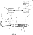
Fig. 1 is an overall schematic view showing an embodiment of an automatic regeneration controller for a particulate filter according to the invention; -
Fig. 2 is a flowchart showing control flow in the embodiment of the automatic regeneration controller for the particulate filter according to the invention; and -
Fig. 3 is the flowchart showing control flow in the embodiment of the automatic regeneration controller for the particulate filter according to the invention. - Next, an embodiment of the invention will be described in conjunction with the drawings.
-
Figs. 1-3 show the embodiment of an automatic regeneration controller for a particulate filter according to the invention.Reference numeral 1 denotes an industrial engine mounted on a crane, a shovel or other constructing machine; and 2, a hydraulic unit as work unit driven by theindustrial engine 1. Exhaust gas 3 discharged from theindustrial engine 1 flows through anexhaust pipe 4 in which incorporated is afilter case 5. Contained in thefilter case 5 on a downstream side is aparticulate filter 6 for capture of particulates in the exhaust gas 3; and contained in thefilter case 5 on an upstream side is anoxidation catalyst 7 for oxidation treatment of unburned HC gas in the exhaust gas 3. - Fuel injection control in the
industrial engine 1 is conducted on the basis of afuel injection signal 8a outputted from anengine controller 8. In theengine controller 8, an accumulation amount of the particulates is estimated on the basis of, for example, a cumulative amount of a difference between estimated production and treatment amounts of the particulates calculated from a difference in pressure before and after theparticulate filter 6, an engine rotation frequency and a load. When the estimated accumulation amount is determined to exceed a set value, afuel injection signal 8a is outputted to conduct post injection at non-ignition timing after the compression top dead center following main injection of the fuel near the compression top dead center (crank angle 0°). - Specifically, the post injection at the non-ignition timing after the compression top dead center following the main injection adds unburned fuel into the exhaust gas 3, so that the unburned fuel generates HC gas with high concentration which is directed to the entry-
side oxidation catalyst 7. - At the same time, collaborative control signals 10 are mutually inputted and outputted between the engine and
unit controllers hydraulic unit 2 as the work unit, so that thehydraulic unit 2 is collaboratively controlled by aunit control signal 9a outputted from theunit controller 9. For load application to thehydraulic unit 2, a hydraulic pump is driven to circulate an operating oil to thereby conduct a load application operation in thehydraulic unit 2. - Further, a load
application cancelation switch 11 is provided to output, to theunit controller 9, acancellation signal 11a for stoppage of the forced load application to thehydraulic unit 2 depending on a situation of thehydraulic unit 2. The loadapplication cancelation switch 11 can be operated by an operator as needs demand. - The embodiment is configured, as shown in the flowchart of
Figs. 2 and3 , such that when the regeneration of theparticulate filter 6 is started by determination in theengine controller 8 of captured particulate accumulation (see step S1), firstly made is determination on whether an idling or light-load operation is conducted or not (see step S2); if the idling or light-load operation being conducted is determined, load request to thehydraulic unit 2 as the work unit is outputted from theengine controller 8 to the unit controller 9 (see step S3). Then, when determination made on whether load application is possible or not (see step S4) is negative or when determination made on whether the loadapplication cancelation switch 11 is off or not (see step S5) is negative, made is determination on whether exhaust temperature is maintainable or not with no load application (see step S6); if the exhaust temperature not maintainable with no load application is determined, then a regeneration stop signal is outputted from theunit controller 9 to the engine controller 8 (see step S7) and a regeneration stop signal reception process is conducted in the engine controller 8 (see step S8), and with no forced load application to the hydraulic unit 2 (see step S9), the post injection or other fuel addition is stopped to stop the automatic regeneration control (see step S10). After the automatic regeneration control is stopped in the above-mentioned step S1, the procedure is returned to the above-mentioned step S2 to determine whether the idling or light-load operation is conducted or not, and controls with determinations similar to those mentioned in the above are repeated. - The configuration is further such that when the determination in the above-mentioned step S6 made on whether the exhaust temperature is maintainable or not with no load application is affirmative, then with no forced load application to the
hydraulic unit 2 as the work unit (see step S11), the post injection or other fuel addition is conducted to continue the automatic regeneration control (see step S12). With the automatic regeneration control being continued in the above-mentioned step S12, if determination made on whether the regeneration of theparticulate filter 6 is completed or not (see step S13) is affirmative, the regeneration is ended; if negative, the procedure is returned to the above-mentioned step S2 to determine whether the idling or light-load operation is conducted or not, and controls with determinations similar to those mentioned in the above are repeated. - Further, the configuration is such that, when the determination made in the above-mentioned step S4 on whether load application is possible or not is affirmative and the determination made in the above-mentioned step S5 on whether load
application cancelation switch 11 is off or not is affirmative, then with the forced load application to thehydraulic unit 2 as the work unit being conducted (see step S14) to intentionally increase the engine load and increase the exhaust temperature by the increased load, the post injection or other fuel addition is conducted to continue the automatic regeneration control (see step S15). With the automatic regeneration control being continued in the above-mentioned step S15, if determination made on whether the regeneration of theparticulate filter 6 is completed or not (see step S13) is affirmative, the regeneration is ended; if negative, the procedure is returned to the above-mentioned step S2 to determine whether the idling or light-load operation is conducted or not, and controls with determinations similar to those mentioned in the above are repeated. - The configuration is such that, when the determination made in the above-mentioned
step 2 on whether the idling or light-load operation is conducted or not is negative, the load has been already applied, so that with no forced load application to thehydraulic unit 2 as the work unit (see step S11), the post injection or other fuel addition is conducted to continue the automatic regeneration control (see step S12). - Next, a mode of operation of the above embodiment will be described.
- When the regeneration of the
particulate filter 6 is started by determination of captured particulate accumulation in the engine controller 8 (see step S1), firstly made is the determination on whether the idling or light-load operation is conducted or not (see step S2); if the idling or light-load operation being conducted is determined, load request to thehydraulic unit 2 as the work unit is outputted from theengine controller 8 to the unit controller 9 (see step S3). - Then, when the determination made on whether the load application is possible or not (see step S4) is negative or the determination made on whether the load
application cancelation switch 11 is off or not (see step S5) is negative, then made is the determination on whether the exhaust temperature is maintainable or not with no load application (see step S6); if the exhaust temperature not maintainable with no load application is determined, then the regeneration stop signal is outputted from theunit controller 9 to the engine controller 8 (see step S7) and the regeneration stop signal reception process is conducted in the engine controller 8 (see step S8), and with no forced load application to the hydraulic unit 2 (see step S9), the post injection or other fuel addition is stopped to stop the automatic regeneration control (see step S10). - After the automatic regeneration control is stopped in the above-mentioned step S1, the procedure is returned to the above-mentioned step S2 to determine whether the idling or light-load operation is conducted or not, and controls with determinations similar to those mentioned in the above are repeated.
- When the determination in the above-mentioned step S6 made on whether exhaust temperature is maintainable with no load application is affirmative, then with no forced load application to the
hydraulic unit 2 as the work unit (see step S11), the post injection or other fuel addition is conducted to continue the automatic regeneration control (see step S12). In this connection, in the shovel or other constructing machine, a load on thehydraulic unit 2 during a work is relatively great and an engine torque is high, so that, with the automatic regeneration control being conducted on the engine side and with the post injection or other fuel addition being conducted, the exhaust temperature can be maintained to be high even if an operator determines to turn on the loadapplication cancelation switch 11 to stop the load application. With the automatic regeneration control being continued in the above-mentioned step S12, if the determination made on whether the regeneration of theparticulate filter 6 is completed or not (see step S13) is affirmative, the regeneration is ended; if negative, the procedure is returned to the above-mentioned step S2 to determine whether the idling or light-load operation is conducted or not, and controls with determinations similar to those mentioned in the above are repeated. - Further, when the determination made in the above-mentioned step S4 on whether load application is possible or not is affirmative and the determination made in the above-mentioned step S5 on whether the load
application cancelation switch 11 is off or not is affirmative, then with the forced load application to thehydraulic unit 2 as the work unit being conducted (see step S14) to intentionally increase the engine load and increase the exhaust temperature by the increased load, the post injection or other fuel addition is conducted to continue the automatic regeneration control (see step S15). With the automatic regeneration control being continued in the above-mentioned step S15, if the determination made on whether the regeneration of theparticulate filter 6 is completed or not (see step S13) is affirmative, the regeneration of theparticulate filter 6 is ended; if negative, the procedure is returned to the above-mentioned step S2 to determine whether the idling or light-load operation is conducted or not, and controls with determinations similar to those mentioned in the above are repeated. - When the determination made in the above-mentioned step S2 on whether the idling or light-load operation is conducted or not is negative, the load has been already applied, so that with no forced load application to the
hydraulic unit 2 as the work unit (see step S11), the post injection or other fuel addition is conducted to continue the automatic regeneration control (see step S12). - In the embodiment, an absolutely fundamental control is such that, with forced load application to the
hydraulic unit 2 as the work unit being conducted (see step S14) to intentionally increase the engine load and increase the exhaust temperature by the increased load, the post injection or other fuel addition is conducted to continue the automatic regeneration control (see step S15). However, when an operator determines, depending upon a situation of thehydraulic unit 2, that the forced load application to thehydraulic unit 2 is to be stopped, the loadapplication cancelation switch 11 can be turned on to stop the load application, resulting in no problem in the work. - In this connection, in the crane or other constructing machine, a load on the
hydraulic unit 2 as the work unit during a work is relatively light and an engine torque is not so high, so that, with the automatic regeneration control being conducted on the engine side and with the post injection or other fuel addition being conducted, if by the operator's determination the loadapplication cancelation switch 11 is turned on to stop the load application, the exhaust temperature may not be maintained to be high. However, in the embodiment, with the automatic regeneration control being conducted on the engine side and with the post injection or other fuel addition being conducted, if by the operator's determination the loadapplication cancelation switch 11 is turned on to stop the load application and the fact of the exhaust temperature being not maintainable to be high is determined in step S6, then the regeneration stop signal is outputted from theunit controller 9 to theengine controller 8 in step S7; the regeneration stop signal reception process is conducted in theengine controller 8 in step S8; with no forced load application to thehydraulic unit 2 in step S9, the post injection or other fuel addition is stopped to stop the automatic regeneration control in step S10, so that deteriorated fuel economy and generation of white smoke can be averted. - Thus, the force load application to the
hydraulic unit 2 as work unit can be stopped depending on a situation of thehydraulic unit 2 to thereby smooth the work. When exhaust temperature cannot be maintained to be high on stoppage of the load application during the automatic regeneration control of theparticulate filter 6, the regeneration of theparticulate filter 6 can be stopped to prevent deteriorated fuel economy and generation of while smoke. - It is to be understood that an automatic regeneration controller for a particulate filter according to the invention is not limited to the above embodiment and that the invention is defined by the appended claims. For example, though the industrial engine with the hydraulic unit as work unit in the constructing machine is described in the embodiment, alternatively the work unit may be an electric generator, a compressor or the like. Though the forced load application to the hydraulic unit is exemplified by a technique that with hydraulic pressure being released, the hydraulic pump is driven to circulate the operating oil, alternatively the load may be applied by intentionally braking a drive system using the work unit. Further, the invention is applicable not only to a constructing machine but also to a forklift or other transporting machine.
- An automatic regeneration controller for a particulate filter according to the invention may be utilized for an industrial engine which drives a work unit using engine power to conduct various works.
-
- 1
- industrial engine
- 2
- hydraulic unit (work unit)
- 3
- exhaust gas
- 4
- exhaust pipe
- 6
- particulate filter
- 7
- oxidation catalyst
- 8
- engine controller
- 8a
- fuel injection signal
- 9
- unit controller
- 9a
- unit control signal
- 10
- collaborative control signal
- 11
- load application cancelation switch
- 11a
- cancellation signal
Claims (5)
- An automatic regeneration controller for a particulate filter (6) wherein an oxidation catalyst (7) and the particulate filter (6) are sequentially arranged in an exhaust pipe (4) of an industrial engine (1) for driving a work unit (2) using engine power to conduct various works, fuel being added to an exhaust gas (3) upstream of the oxidation catalyst (7) with a load being forcedly applied to said work unit (2) to intently increase an engine load and increase an exhaust temperature by said increased load, said added fuel undergoing oxidation reaction on the oxidation catalyst (7) and resultant reaction heat burning captured particulates in the particulate filter (6) just behind to thereby conduct regeneration of said particulate filter (6), comprising
an engine controller (8) for outputting a fuel injection signal (8a) to said industrial engine (1) when an estimated accumulation amount of said particulates is determined to exceed a set value; and
a unit controller (9) for outputting a unit control signal (9a) to said work unit (2) for collaborative control thereof, collaborative control signals (10) being mutually inputted and outputted between said unit and engine controllers (9 and 8), characterized in that it further comprises
a load application cancelation switch (11) for outputting a cancellation signal (11a) to said unit controller (9) depending upon a situation of said work unit (2) to stop the forced load application to said work unit (2),
the automatic regeneration controller being configured such that, with the regeneration of the particulate filter (6) being started by determination of captured particulate accumulation, with an idling or light-load operation being conducted, and with load request to said work unit (2) being outputted from said engine controller (8) to said unit controller (9), determination is made on whether load application is possible or not and when the load application is not possible or the load application cancelation switch (11) is on and, in addition, maintaining of an exhaust temperature with no load application is not possible, then a regeneration stop signal is outputted from said unit controller (9) to said engine controller (8) to conduct a regeneration stop signal reception process in said engine controller (8) to thereby stop, with no forced load application to the work unit (2), the fuel addition to stop the automatic regeneration control. - The automatic regeneration controller for the particulate filter (6) as claimed in claim 1, configured such that, with the regeneration of the particulate filter (6) being started by determination of captured particulate accumulation, with the idling or light-load operation being conducted, and with load request to said work unit (2) being outputted from said engine controller (8) to said unit controller (9), determination is made on whether load application is possible or not and when the load application is not possible or the load application cancelation switch (11) is on and, in addition, maintaining the exhaust temperature with no load application is possible, then the fuel addition is conducted and the automatic regeneration control is continued with no forced load application to said work unit (2).
- The automatic regeneration controller for a particulate filter (6) as claimed in claim 1 or 2, configured such that, with regeneration of the particulate filter (6) being started by determination of captured particulate accumulation, with the idling or light-load operation being conducted, and with load request to said work unit (2) being outputted from said engine controller (8) to said unit controller (9), determination is made on whether load application is possible or not and when the load application is possible and the load application cancelation switch (11) is off, then the fuel addition is conducted and the automatic regeneration control is continued with the forced load application to said work unit (2) being conducted to intentionally increase the engine load and increase the exhaust temperature by said increased load.
- The automatic regeneration controller for a particulate filter (6) as claimed in claim 1 or 2, configured such that, with regeneration of the particulate filter (6) being started by determination of captured particulate accumulation and with no idling or light-load operation being conducted, the fuel addition is conducted and the automatic regeneration control is continued with no forced load application to said work unit (2).
- The automatic regeneration controller for a particulate filter (6) as claimed in claim 3, configured such that, with regeneration of the particulate filter (6) being started by determination of captured particulate accumulation and with no idling or light-load operation being conducted, the fuel addition is conducted and the automatic regeneration control is continued with no forced load application to said work unit (2) .
Applications Claiming Priority (2)
| Application Number | Priority Date | Filing Date | Title |
|---|---|---|---|
| JP2012280693A JP6071530B2 (en) | 2012-12-25 | 2012-12-25 | Particulate filter automatic regeneration control device |
| PCT/JP2013/007219 WO2014103196A1 (en) | 2012-12-25 | 2013-12-09 | Automatic regeneration control device for particulate filter |
Publications (3)
| Publication Number | Publication Date |
|---|---|
| EP2940263A1 EP2940263A1 (en) | 2015-11-04 |
| EP2940263A4 EP2940263A4 (en) | 2016-08-03 |
| EP2940263B1 true EP2940263B1 (en) | 2019-07-24 |
Family
ID=51020320
Family Applications (1)
| Application Number | Title | Priority Date | Filing Date |
|---|---|---|---|
| EP13869791.7A Not-in-force EP2940263B1 (en) | 2012-12-25 | 2013-12-09 | Automatic regeneration control device for particulate filter |
Country Status (4)
| Country | Link |
|---|---|
| US (1) | US9850793B2 (en) |
| EP (1) | EP2940263B1 (en) |
| JP (1) | JP6071530B2 (en) |
| WO (1) | WO2014103196A1 (en) |
Families Citing this family (3)
| Publication number | Priority date | Publication date | Assignee | Title |
|---|---|---|---|---|
| JP2016113900A (en) * | 2014-12-11 | 2016-06-23 | 日野自動車株式会社 | Particulate filter regeneration method |
| JP2021060026A (en) * | 2019-10-09 | 2021-04-15 | トヨタ自動車株式会社 | Vehicle and control method for the same |
| US20220279718A1 (en) * | 2021-03-04 | 2022-09-08 | Deere & Company | State-based mechanism for performing engine regeneration procedure |
Family Cites Families (10)
| Publication number | Priority date | Publication date | Assignee | Title |
|---|---|---|---|---|
| JP2005155574A (en) * | 2003-11-28 | 2005-06-16 | Hino Motors Ltd | Exhaust emission control device |
| EP2208872B1 (en) * | 2007-11-06 | 2017-12-13 | Hitachi Construction Machinery Co., Ltd. | Work vehicle with exhaust purification system |
| JP2009191654A (en) * | 2008-02-12 | 2009-08-27 | Hino Motors Ltd | Method of regenerating particulate filter |
| JP5101436B2 (en) * | 2008-08-26 | 2012-12-19 | ヤンマー株式会社 | diesel engine |
| JP4774096B2 (en) * | 2008-11-17 | 2011-09-14 | 日立建機株式会社 | Exhaust gas purification system for work machines |
| JP2011017256A (en) * | 2009-07-07 | 2011-01-27 | Yanmar Co Ltd | Engine device |
| US9032718B2 (en) | 2009-07-02 | 2015-05-19 | Yanmar Co., Ltd | Engine device |
| JP5614996B2 (en) * | 2010-01-28 | 2014-10-29 | 三菱重工業株式会社 | Exhaust gas treatment method and apparatus for internal combustion engine |
| JP5548882B2 (en) * | 2010-08-27 | 2014-07-16 | 日立建機株式会社 | Exhaust gas purification system for work vehicles |
| KR101737637B1 (en) * | 2010-12-24 | 2017-05-18 | 두산인프라코어 주식회사 | System and method of active DPF regeneration for construction machinery comprising electro-hydraulic pump |
-
2012
- 2012-12-25 JP JP2012280693A patent/JP6071530B2/en active Active
-
2013
- 2013-12-09 WO PCT/JP2013/007219 patent/WO2014103196A1/en active Application Filing
- 2013-12-09 US US14/655,093 patent/US9850793B2/en not_active Expired - Fee Related
- 2013-12-09 EP EP13869791.7A patent/EP2940263B1/en not_active Not-in-force
Non-Patent Citations (1)
| Title |
|---|
| None * |
Also Published As
| Publication number | Publication date |
|---|---|
| EP2940263A4 (en) | 2016-08-03 |
| US20150369099A1 (en) | 2015-12-24 |
| EP2940263A1 (en) | 2015-11-04 |
| WO2014103196A1 (en) | 2014-07-03 |
| JP6071530B2 (en) | 2017-02-01 |
| JP2014125891A (en) | 2014-07-07 |
| US9850793B2 (en) | 2017-12-26 |
Similar Documents
| Publication | Publication Date | Title |
|---|---|---|
| EP1980725B1 (en) | Control method of exhaust gas purification system and exhaust gas purification system | |
| CN102947558B (en) | Waste gas cleaning system | |
| JP4273911B2 (en) | Vehicle exhaust purification system | |
| JP4169076B2 (en) | Exhaust gas purification system control method and exhaust gas purification system | |
| US8011178B2 (en) | Method for controlling exhaust gas purification system and exhaust gas purification system | |
| JP3979437B1 (en) | Exhaust gas purification system control method and exhaust gas purification system | |
| EP2041406B1 (en) | Method and system for regenerating an exhaust gas purification unit. | |
| US20090235645A1 (en) | Exhaust purification system, control apparatus and control method therefor | |
| CN101988407B (en) | Exhaust-gas processing device for a diesel engine | |
| CN102939440B (en) | Dpf system | |
| WO2011155590A1 (en) | Exhaust-gas purification system | |
| WO2011155589A1 (en) | Exhaust gas purification system | |
| EP2940263B1 (en) | Automatic regeneration control device for particulate filter | |
| CN202611809U (en) | Engine diesel particulate filter (DPF) controllable regeneration system | |
| US20080022657A1 (en) | Power source thermal management and emissions reduction system | |
| KR102127543B1 (en) | Exhaust gas purification system | |
| JP2004150417A (en) | Exhaust emission control device | |
| JP5471834B2 (en) | Exhaust gas purification system | |
| RU2546932C2 (en) | Emissions cleaning method and system | |
| RU2423614C2 (en) | Procedure and system for regeneration of device for purification of burnt gases | |
| WO2011125287A1 (en) | Method and device for preventing fuel freezing in a postprocessing burner system | |
| JP2009191654A (en) | Method of regenerating particulate filter | |
| JP2016006311A (en) | Diesel engine exhaust emission control system and diesel engine exhaust emission control method | |
| GB2579079A (en) | Method of controlling operation of an exhaust gas treatment apparatus | |
| JP2017129019A (en) | Manual regeneration method of particulate filter |
Legal Events
| Date | Code | Title | Description |
|---|---|---|---|
| PUAI | Public reference made under article 153(3) epc to a published international application that has entered the european phase |
Free format text: ORIGINAL CODE: 0009012 |
|
| 17P | Request for examination filed |
Effective date: 20150630 |
|
| AK | Designated contracting states |
Kind code of ref document: A1 Designated state(s): AL AT BE BG CH CY CZ DE DK EE ES FI FR GB GR HR HU IE IS IT LI LT LU LV MC MK MT NL NO PL PT RO RS SE SI SK SM TR |
|
| AX | Request for extension of the european patent |
Extension state: BA ME |
|
| DAX | Request for extension of the european patent (deleted) | ||
| A4 | Supplementary search report drawn up and despatched |
Effective date: 20160701 |
|
| RIC1 | Information provided on ipc code assigned before grant |
Ipc: F02D 29/00 20060101ALI20160627BHEP Ipc: F01N 9/00 20060101ALI20160627BHEP Ipc: F01N 3/10 20060101ALI20160627BHEP Ipc: F01N 3/029 20060101ALI20160627BHEP Ipc: F01N 3/025 20060101ALI20160627BHEP Ipc: F02D 29/04 20060101ALI20160627BHEP Ipc: F02D 41/04 20060101ALI20160627BHEP Ipc: F01N 3/023 20060101AFI20160627BHEP |
|
| STAA | Information on the status of an ep patent application or granted ep patent |
Free format text: STATUS: EXAMINATION IS IN PROGRESS |
|
| 17Q | First examination report despatched |
Effective date: 20180326 |
|
| GRAP | Despatch of communication of intention to grant a patent |
Free format text: ORIGINAL CODE: EPIDOSNIGR1 |
|
| STAA | Information on the status of an ep patent application or granted ep patent |
Free format text: STATUS: GRANT OF PATENT IS INTENDED |
|
| INTG | Intention to grant announced |
Effective date: 20190226 |
|
| GRAS | Grant fee paid |
Free format text: ORIGINAL CODE: EPIDOSNIGR3 |
|
| GRAA | (expected) grant |
Free format text: ORIGINAL CODE: 0009210 |
|
| STAA | Information on the status of an ep patent application or granted ep patent |
Free format text: STATUS: THE PATENT HAS BEEN GRANTED |
|
| AK | Designated contracting states |
Kind code of ref document: B1 Designated state(s): AL AT BE BG CH CY CZ DE DK EE ES FI FR GB GR HR HU IE IS IT LI LT LU LV MC MK MT NL NO PL PT RO RS SE SI SK SM TR |
|
| REG | Reference to a national code |
Ref country code: GB Ref legal event code: FG4D |
|
| REG | Reference to a national code |
Ref country code: CH Ref legal event code: EP |
|
| REG | Reference to a national code |
Ref country code: DE Ref legal event code: R096 Ref document number: 602013058332 Country of ref document: DE |
|
| REG | Reference to a national code |
Ref country code: AT Ref legal event code: REF Ref document number: 1158453 Country of ref document: AT Kind code of ref document: T Effective date: 20190815 |
|
| REG | Reference to a national code |
Ref country code: IE Ref legal event code: FG4D |
|
| REG | Reference to a national code |
Ref country code: NL Ref legal event code: MP Effective date: 20190724 |
|
| REG | Reference to a national code |
Ref country code: LT Ref legal event code: MG4D |
|
| REG | Reference to a national code |
Ref country code: AT Ref legal event code: MK05 Ref document number: 1158453 Country of ref document: AT Kind code of ref document: T Effective date: 20190724 |
|
| PG25 | Lapsed in a contracting state [announced via postgrant information from national office to epo] |
Ref country code: FI Free format text: LAPSE BECAUSE OF FAILURE TO SUBMIT A TRANSLATION OF THE DESCRIPTION OR TO PAY THE FEE WITHIN THE PRESCRIBED TIME-LIMIT Effective date: 20190724 Ref country code: SE Free format text: LAPSE BECAUSE OF FAILURE TO SUBMIT A TRANSLATION OF THE DESCRIPTION OR TO PAY THE FEE WITHIN THE PRESCRIBED TIME-LIMIT Effective date: 20190724 Ref country code: BG Free format text: LAPSE BECAUSE OF FAILURE TO SUBMIT A TRANSLATION OF THE DESCRIPTION OR TO PAY THE FEE WITHIN THE PRESCRIBED TIME-LIMIT Effective date: 20191024 Ref country code: NL Free format text: LAPSE BECAUSE OF FAILURE TO SUBMIT A TRANSLATION OF THE DESCRIPTION OR TO PAY THE FEE WITHIN THE PRESCRIBED TIME-LIMIT Effective date: 20190724 Ref country code: AT Free format text: LAPSE BECAUSE OF FAILURE TO SUBMIT A TRANSLATION OF THE DESCRIPTION OR TO PAY THE FEE WITHIN THE PRESCRIBED TIME-LIMIT Effective date: 20190724 Ref country code: HR Free format text: LAPSE BECAUSE OF FAILURE TO SUBMIT A TRANSLATION OF THE DESCRIPTION OR TO PAY THE FEE WITHIN THE PRESCRIBED TIME-LIMIT Effective date: 20190724 Ref country code: NO Free format text: LAPSE BECAUSE OF FAILURE TO SUBMIT A TRANSLATION OF THE DESCRIPTION OR TO PAY THE FEE WITHIN THE PRESCRIBED TIME-LIMIT Effective date: 20191024 Ref country code: LT Free format text: LAPSE BECAUSE OF FAILURE TO SUBMIT A TRANSLATION OF THE DESCRIPTION OR TO PAY THE FEE WITHIN THE PRESCRIBED TIME-LIMIT Effective date: 20190724 Ref country code: PT Free format text: LAPSE BECAUSE OF FAILURE TO SUBMIT A TRANSLATION OF THE DESCRIPTION OR TO PAY THE FEE WITHIN THE PRESCRIBED TIME-LIMIT Effective date: 20191125 |
|
| PG25 | Lapsed in a contracting state [announced via postgrant information from national office to epo] |
Ref country code: LV Free format text: LAPSE BECAUSE OF FAILURE TO SUBMIT A TRANSLATION OF THE DESCRIPTION OR TO PAY THE FEE WITHIN THE PRESCRIBED TIME-LIMIT Effective date: 20190724 Ref country code: GR Free format text: LAPSE BECAUSE OF FAILURE TO SUBMIT A TRANSLATION OF THE DESCRIPTION OR TO PAY THE FEE WITHIN THE PRESCRIBED TIME-LIMIT Effective date: 20191025 Ref country code: ES Free format text: LAPSE BECAUSE OF FAILURE TO SUBMIT A TRANSLATION OF THE DESCRIPTION OR TO PAY THE FEE WITHIN THE PRESCRIBED TIME-LIMIT Effective date: 20190724 Ref country code: AL Free format text: LAPSE BECAUSE OF FAILURE TO SUBMIT A TRANSLATION OF THE DESCRIPTION OR TO PAY THE FEE WITHIN THE PRESCRIBED TIME-LIMIT Effective date: 20190724 Ref country code: RS Free format text: LAPSE BECAUSE OF FAILURE TO SUBMIT A TRANSLATION OF THE DESCRIPTION OR TO PAY THE FEE WITHIN THE PRESCRIBED TIME-LIMIT Effective date: 20190724 Ref country code: IS Free format text: LAPSE BECAUSE OF FAILURE TO SUBMIT A TRANSLATION OF THE DESCRIPTION OR TO PAY THE FEE WITHIN THE PRESCRIBED TIME-LIMIT Effective date: 20191124 |
|
| PG25 | Lapsed in a contracting state [announced via postgrant information from national office to epo] |
Ref country code: TR Free format text: LAPSE BECAUSE OF FAILURE TO SUBMIT A TRANSLATION OF THE DESCRIPTION OR TO PAY THE FEE WITHIN THE PRESCRIBED TIME-LIMIT Effective date: 20190724 |
|
| PG25 | Lapsed in a contracting state [announced via postgrant information from national office to epo] |
Ref country code: RO Free format text: LAPSE BECAUSE OF FAILURE TO SUBMIT A TRANSLATION OF THE DESCRIPTION OR TO PAY THE FEE WITHIN THE PRESCRIBED TIME-LIMIT Effective date: 20190724 Ref country code: EE Free format text: LAPSE BECAUSE OF FAILURE TO SUBMIT A TRANSLATION OF THE DESCRIPTION OR TO PAY THE FEE WITHIN THE PRESCRIBED TIME-LIMIT Effective date: 20190724 Ref country code: PL Free format text: LAPSE BECAUSE OF FAILURE TO SUBMIT A TRANSLATION OF THE DESCRIPTION OR TO PAY THE FEE WITHIN THE PRESCRIBED TIME-LIMIT Effective date: 20190724 Ref country code: IT Free format text: LAPSE BECAUSE OF FAILURE TO SUBMIT A TRANSLATION OF THE DESCRIPTION OR TO PAY THE FEE WITHIN THE PRESCRIBED TIME-LIMIT Effective date: 20190724 Ref country code: DK Free format text: LAPSE BECAUSE OF FAILURE TO SUBMIT A TRANSLATION OF THE DESCRIPTION OR TO PAY THE FEE WITHIN THE PRESCRIBED TIME-LIMIT Effective date: 20190724 |
|
| PGFP | Annual fee paid to national office [announced via postgrant information from national office to epo] |
Ref country code: GB Payment date: 20191211 Year of fee payment: 7 Ref country code: DE Payment date: 20191219 Year of fee payment: 7 |
|
| PG25 | Lapsed in a contracting state [announced via postgrant information from national office to epo] |
Ref country code: SK Free format text: LAPSE BECAUSE OF FAILURE TO SUBMIT A TRANSLATION OF THE DESCRIPTION OR TO PAY THE FEE WITHIN THE PRESCRIBED TIME-LIMIT Effective date: 20190724 Ref country code: CZ Free format text: LAPSE BECAUSE OF FAILURE TO SUBMIT A TRANSLATION OF THE DESCRIPTION OR TO PAY THE FEE WITHIN THE PRESCRIBED TIME-LIMIT Effective date: 20190724 Ref country code: SM Free format text: LAPSE BECAUSE OF FAILURE TO SUBMIT A TRANSLATION OF THE DESCRIPTION OR TO PAY THE FEE WITHIN THE PRESCRIBED TIME-LIMIT Effective date: 20190724 Ref country code: IS Free format text: LAPSE BECAUSE OF FAILURE TO SUBMIT A TRANSLATION OF THE DESCRIPTION OR TO PAY THE FEE WITHIN THE PRESCRIBED TIME-LIMIT Effective date: 20200224 |
|
| REG | Reference to a national code |
Ref country code: DE Ref legal event code: R097 Ref document number: 602013058332 Country of ref document: DE |
|
| PLBE | No opposition filed within time limit |
Free format text: ORIGINAL CODE: 0009261 |
|
| STAA | Information on the status of an ep patent application or granted ep patent |
Free format text: STATUS: NO OPPOSITION FILED WITHIN TIME LIMIT |
|
| PG2D | Information on lapse in contracting state deleted |
Ref country code: IS |
|
| REG | Reference to a national code |
Ref country code: CH Ref legal event code: PL |
|
| 26N | No opposition filed |
Effective date: 20200603 |
|
| REG | Reference to a national code |
Ref country code: BE Ref legal event code: MM Effective date: 20191231 |
|
| PG25 | Lapsed in a contracting state [announced via postgrant information from national office to epo] |
Ref country code: MC Free format text: LAPSE BECAUSE OF FAILURE TO SUBMIT A TRANSLATION OF THE DESCRIPTION OR TO PAY THE FEE WITHIN THE PRESCRIBED TIME-LIMIT Effective date: 20190724 Ref country code: SI Free format text: LAPSE BECAUSE OF FAILURE TO SUBMIT A TRANSLATION OF THE DESCRIPTION OR TO PAY THE FEE WITHIN THE PRESCRIBED TIME-LIMIT Effective date: 20190724 |
|
| PG25 | Lapsed in a contracting state [announced via postgrant information from national office to epo] |
Ref country code: LU Free format text: LAPSE BECAUSE OF NON-PAYMENT OF DUE FEES Effective date: 20191209 Ref country code: FR Free format text: LAPSE BECAUSE OF NON-PAYMENT OF DUE FEES Effective date: 20191231 Ref country code: IE Free format text: LAPSE BECAUSE OF NON-PAYMENT OF DUE FEES Effective date: 20191209 |
|
| PG25 | Lapsed in a contracting state [announced via postgrant information from national office to epo] |
Ref country code: BE Free format text: LAPSE BECAUSE OF NON-PAYMENT OF DUE FEES Effective date: 20191231 Ref country code: LI Free format text: LAPSE BECAUSE OF NON-PAYMENT OF DUE FEES Effective date: 20191231 Ref country code: CH Free format text: LAPSE BECAUSE OF NON-PAYMENT OF DUE FEES Effective date: 20191231 |
|
| PG25 | Lapsed in a contracting state [announced via postgrant information from national office to epo] |
Ref country code: CY Free format text: LAPSE BECAUSE OF FAILURE TO SUBMIT A TRANSLATION OF THE DESCRIPTION OR TO PAY THE FEE WITHIN THE PRESCRIBED TIME-LIMIT Effective date: 20190724 |
|
| REG | Reference to a national code |
Ref country code: DE Ref legal event code: R119 Ref document number: 602013058332 Country of ref document: DE |
|
| PG25 | Lapsed in a contracting state [announced via postgrant information from national office to epo] |
Ref country code: HU Free format text: LAPSE BECAUSE OF FAILURE TO SUBMIT A TRANSLATION OF THE DESCRIPTION OR TO PAY THE FEE WITHIN THE PRESCRIBED TIME-LIMIT; INVALID AB INITIO Effective date: 20131209 Ref country code: MT Free format text: LAPSE BECAUSE OF FAILURE TO SUBMIT A TRANSLATION OF THE DESCRIPTION OR TO PAY THE FEE WITHIN THE PRESCRIBED TIME-LIMIT Effective date: 20190724 |
|
| GBPC | Gb: european patent ceased through non-payment of renewal fee |
Effective date: 20201209 |
|
| PG25 | Lapsed in a contracting state [announced via postgrant information from national office to epo] |
Ref country code: DE Free format text: LAPSE BECAUSE OF NON-PAYMENT OF DUE FEES Effective date: 20210701 Ref country code: GB Free format text: LAPSE BECAUSE OF NON-PAYMENT OF DUE FEES Effective date: 20201209 |
|
| PG25 | Lapsed in a contracting state [announced via postgrant information from national office to epo] |
Ref country code: MK Free format text: LAPSE BECAUSE OF FAILURE TO SUBMIT A TRANSLATION OF THE DESCRIPTION OR TO PAY THE FEE WITHIN THE PRESCRIBED TIME-LIMIT Effective date: 20190724 |