EP2940259A1 - Power generation system, and maintenance method for power generation system - Google Patents
Power generation system, and maintenance method for power generation system Download PDFInfo
- Publication number
- EP2940259A1 EP2940259A1 EP13869461.7A EP13869461A EP2940259A1 EP 2940259 A1 EP2940259 A1 EP 2940259A1 EP 13869461 A EP13869461 A EP 13869461A EP 2940259 A1 EP2940259 A1 EP 2940259A1
- Authority
- EP
- European Patent Office
- Prior art keywords
- medium
- valve
- power generation
- generation system
- maintenance
- Prior art date
- Legal status (The legal status is an assumption and is not a legal conclusion. Google has not performed a legal analysis and makes no representation as to the accuracy of the status listed.)
- Granted
Links
Images


Classifications
-
- F—MECHANICAL ENGINEERING; LIGHTING; HEATING; WEAPONS; BLASTING
- F01—MACHINES OR ENGINES IN GENERAL; ENGINE PLANTS IN GENERAL; STEAM ENGINES
- F01K—STEAM ENGINE PLANTS; STEAM ACCUMULATORS; ENGINE PLANTS NOT OTHERWISE PROVIDED FOR; ENGINES USING SPECIAL WORKING FLUIDS OR CYCLES
- F01K13/00—General layout or general methods of operation of complete plants
- F01K13/02—Controlling, e.g. stopping or starting
-
- F—MECHANICAL ENGINEERING; LIGHTING; HEATING; WEAPONS; BLASTING
- F01—MACHINES OR ENGINES IN GENERAL; ENGINE PLANTS IN GENERAL; STEAM ENGINES
- F01D—NON-POSITIVE DISPLACEMENT MACHINES OR ENGINES, e.g. STEAM TURBINES
- F01D21/00—Shutting-down of machines or engines, e.g. in emergency; Regulating, controlling, or safety means not otherwise provided for
-
- F—MECHANICAL ENGINEERING; LIGHTING; HEATING; WEAPONS; BLASTING
- F01—MACHINES OR ENGINES IN GENERAL; ENGINE PLANTS IN GENERAL; STEAM ENGINES
- F01K—STEAM ENGINE PLANTS; STEAM ACCUMULATORS; ENGINE PLANTS NOT OTHERWISE PROVIDED FOR; ENGINES USING SPECIAL WORKING FLUIDS OR CYCLES
- F01K25/00—Plants or engines characterised by use of special working fluids, not otherwise provided for; Plants operating in closed cycles and not otherwise provided for
- F01K25/08—Plants or engines characterised by use of special working fluids, not otherwise provided for; Plants operating in closed cycles and not otherwise provided for using special vapours
- F01K25/10—Plants or engines characterised by use of special working fluids, not otherwise provided for; Plants operating in closed cycles and not otherwise provided for using special vapours the vapours being cold, e.g. ammonia, carbon dioxide, ether
-
- F—MECHANICAL ENGINEERING; LIGHTING; HEATING; WEAPONS; BLASTING
- F01—MACHINES OR ENGINES IN GENERAL; ENGINE PLANTS IN GENERAL; STEAM ENGINES
- F01D—NON-POSITIVE DISPLACEMENT MACHINES OR ENGINES, e.g. STEAM TURBINES
- F01D25/00—Component parts, details, or accessories, not provided for in, or of interest apart from, other groups
- F01D25/28—Supporting or mounting arrangements, e.g. for turbine casing
- F01D25/285—Temporary support structures, e.g. for testing, assembling, installing, repairing; Assembly methods using such structures
-
- F—MECHANICAL ENGINEERING; LIGHTING; HEATING; WEAPONS; BLASTING
- F05—INDEXING SCHEMES RELATING TO ENGINES OR PUMPS IN VARIOUS SUBCLASSES OF CLASSES F01-F04
- F05D—INDEXING SCHEME FOR ASPECTS RELATING TO NON-POSITIVE-DISPLACEMENT MACHINES OR ENGINES, GAS-TURBINES OR JET-PROPULSION PLANTS
- F05D2230/00—Manufacture
- F05D2230/72—Maintenance
-
- F—MECHANICAL ENGINEERING; LIGHTING; HEATING; WEAPONS; BLASTING
- F05—INDEXING SCHEMES RELATING TO ENGINES OR PUMPS IN VARIOUS SUBCLASSES OF CLASSES F01-F04
- F05D—INDEXING SCHEME FOR ASPECTS RELATING TO NON-POSITIVE-DISPLACEMENT MACHINES OR ENGINES, GAS-TURBINES OR JET-PROPULSION PLANTS
- F05D2230/00—Manufacture
- F05D2230/80—Repairing, retrofitting or upgrading methods
-
- F—MECHANICAL ENGINEERING; LIGHTING; HEATING; WEAPONS; BLASTING
- F05—INDEXING SCHEMES RELATING TO ENGINES OR PUMPS IN VARIOUS SUBCLASSES OF CLASSES F01-F04
- F05D—INDEXING SCHEME FOR ASPECTS RELATING TO NON-POSITIVE-DISPLACEMENT MACHINES OR ENGINES, GAS-TURBINES OR JET-PROPULSION PLANTS
- F05D2260/00—Function
- F05D2260/02—Transport and handling during maintenance and repair
Definitions
- the amount of the medium within the cycle circuit 5 in the above power generation systems is large, and substantial time for recovery of the medium, vacuuming when the inside of the cycle circuit 5 is filled with the medium after the end of the maintenance, or the like is required.
- the operating time monitoring unit can output a predetermined signal, for example, through lighting of an indicator lamp, generation of an alarm sound, or the like, and maintenance can be performed at a suitable timing.
- chlorofluocarbon media such as HFC-134a, HFC245fa, HFO-1234yf, and HFO-1234ze, can be used as the medium of the medium circuit 22.
- the medium circuit 22 includes a circulation pump 23, a preheater 24, an evaporator 25, a turbine (expander) 26, and a condenser 27.
- the on-off valve 43 is closed and then the on-off valves 40A and 40B are opened. From this state, the power generation module 50A for which maintenance has been performed is restarted.
- the on-off valves 40A and 40B are provided on the upstream side and the downstream side of the turbine 26 serving as a maintenance target in the medium circuit 22, and the service port 42 is provided between the on-off valves 40A and 40B. Accordingly, during the maintenance of the turbine 26, the on-off valves 40A and 40B may be closed, and entering or departing of the medium in only a partial section including the turbine 26 between the on-off valves 40A and 40B in the medium circuit 22 may be performed.
- the time taken for the extraction or vacuuming of the medium or the filling with the medium can be shortened, and the operation rate of the power generation system can be enhanced by shortening a maintenance period. Additionally, since a small amount of a medium is also required during maintenance, maintenance costs can be reduced.
- control unit 35 is adapted so as to preferentially stop operation from a module equipped with the turbine 26 having the longest operating time when the number of modules to be operated among the plurality of power generation modules 60A, 60B, 60C, ... is reduced.
Landscapes
- Engineering & Computer Science (AREA)
- Mechanical Engineering (AREA)
- General Engineering & Computer Science (AREA)
- Chemical & Material Sciences (AREA)
- Combustion & Propulsion (AREA)
- Engine Equipment That Uses Special Cycles (AREA)
Abstract
Description
- The present invention relates to a power generation system that performs power generation, using exhaust heat from vessels, factories, gas turbines, or the like, the heat of the earth, solar heat, temperature difference between cooler deep and warmer shallow ocean waters, and the like as heat sources, and a maintenance method for a power generation system.
- Priority is claimed on Japanese Patent Application No.
2012-288964, filed December 28, 2012 - In recent years, Rankine cycle type power generation systems have been considered as power generation systems that perform power generation, using exhaust heat from vessels, factories, gas turbines, or the like, the heat of the earth, solar heat, temperature difference between cooler deep and warmer shallow ocean waters, and the like as heat sources, from viewpoints of effective energy use, environmental preservation, or the like (for example, refer to
Patent Documents 1 to 3). In this case, when the heat sources as described above are used, for example, organic fluids that are media (for example, chlorofluocarbon media or the like) having a boiling point lower than that of water are used. - In such power generation systems, as shown in
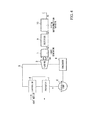
FIG. 4 , a medium circulates within acycle circuit 5 having apreheater 1, anevaporator 2, aturbine 3, and acondenser 4, using acirculation pump 6. - A heat medium that has recovered heat from the heat sources as described above is sent into the
evaporator 2, is made to perform heat exchange with the medium, and evaporates and gasifies the medium. Additionally, the heat medium that has passed through theevaporator 2 preheats the medium in thepreheater 1 provided in the preceding stage of theevaporator 2. - The gasified medium expands in the
turbine 3, thereby rotationally driving amain shaft 3a and driving agenerator 7. The medium that has expanded in theturbine 3 is condensed in thecondenser 4 and returns to thecirculation pump 6. - An alternating current (AC) output as the
generator 7 is driven is converted into a direct current (DC) in arectifier 9, and the converted direct current is re-converted into an alternating current in asystem interconnection inverter 10 and is output to the outside as generated electric power. -
- [Patent Document 1] Japanese Unexamined Patent Application, First Publication No.
2006-299996 - [Patent Document 2] Japanese Unexamined Patent Application, First Publication No.
2006-313048 - [Patent Document 3] Japanese Unexamined Patent Application, First Publication No.
2006-313049 - In the power generation systems as described above, for example, it is necessary to perform maintenance, such as checking or replacement of consumable parts, such as bearings of the
main shaft 3a of theturbine 3 or the like. - In this case, it is necessary to recover the medium within the
cycle circuit 5 prior to maintenance from the viewpoints of environmental preservation, medium cost, or the like. - However, the amount of the medium within the
cycle circuit 5 in the above power generation systems is large, and substantial time for recovery of the medium, vacuuming when the inside of thecycle circuit 5 is filled with the medium after the end of the maintenance, or the like is required. - As a result, since a maintenance period is prolonged, and the entire power generation system cannot be used during that time, an operation rate decreases, and economic loss is also large.
- The invention provides a power generation system and a maintenance method for a power generation system that can shorten a maintenance period and enhance the operation rate of a power generation system.
- According to a first aspect of the invention, a power generation system includes an evaporator configured to heat the medium using heat of an external source so as to evaporate the medium; an expander configured to be driven using the medium evaporated by the evaporator; a condenser configured to condense the medium discharged from the expander; a generator configured to be driven by the expander to generate power; a first on-off valve installed on the medium circuit at an upstream side of a maintenance target device including at least one of the circulation pump, the evaporator, the expander, and the condenser, and is capable of shutting off the flow of the medium through the medium circuit; a second on-off valve installed on the medium circuit at a downstream side of the maintenance target device, and is capable of shutting off the flow of the medium through the medium circuit; a port configured to be communicable with the medium circuit between the first on-off valve and the second on-off valve; and a third on-off valve installed on the port.
- According to the power generation system, when the maintenance target device is maintained, after the first on-off valve and the second on-off valve are closed, the third on-off valve is opened to recover the medium between the first on-off valve and the second on-off valve after the medium recovery device that recovers the medium is connected to the port. Then, after the maintenance of the maintenance target device is completed, the section between the first on-off valve and the second on-off valve is vacuumed by connecting the vacuum pump to the port, and the third on-off valve is closed. Next, the third on-off valve is opened by connecting the medium supply device that supplies the medium to the port, the section between the first on-off valve and the second on-off valve is filled with the medium from the medium supply device, and then the third on-off valve is closed. Then, the power generation system is restarted by opening the first on-off valve and the second on-off valve and starting the circulation pump.
- In this way, when the maintenance target device is maintained, it is not necessary to extract the medium in the entire medium circuit, and only the medium between the first on-off valve and the second on-off valve may be extracted. Additionally, the vacuuming performed when the filling with the medium is performed after maintenance may also be performed between the first on-off valve and the second on-off valve.
- The maintenance target device may include at least one of the circulation pump, the evaporator, the expander, and the condenser or may include two or more among these. Additionally, the two or more maintenance target devices may include the first on-off valve, the second on-off valve, the port, and the third on-off valve.
- According to a second aspect of the invention, a plurality of sets of power generation units each including the medium circuit, the circulation pump, the evaporator, the expander, the condenser, and the generator may be provided in parallel, and the first on-off valve, the second on-off valve, the port, and the third on-off valve may be installed on the medium circuit of each of the power generation units.
- Accordingly, even in the configuration in which the plurality of medium circuits are provided in parallel, maintenance can be similarly performed in the respective medium circuits.
- According to a third aspect of the invention, the medium circuit may branch into a plurality of branched pipes between the downstream side of the evaporator and the upstream side of the condenser, and the maintenance target device, the first on-off valve, the second on-off valve, the port, and the third on-off valve may be installed on each of the branched pipes.
- Accordingly, even in the configuration in which the plurality of sets of maintenance target devices are provided in parallel in one medium circuit, maintenance can be performed in a manner similar to the above for the respective maintenance target devices.
- According to a fourth aspect of the invention, the power generation system may further include an operating time measuring unit configured to measure an integrated value of the operating time of the maintenance target device, and an operating time monitoring unit configured to output a predetermined signal when the integrated value in the operating time measuring unit reaches a predetermined specified value.
- In this way, if the integrated value of the operating time of the maintenance target device reaches the specified value, the operating time monitoring unit can output a predetermined signal, for example, through lighting of an indicator lamp, generation of an alarm sound, or the like, and maintenance can be performed at a suitable timing.
- According to a fifth aspect of the invention, a plurality of the maintenance target devices may be provided in parallel, the power generation system may further include the control unit that increases or reduces the number of maintenance target devices to be operated in accordance with the input from the heat source or the output from the generator, and the control unit may preferentially stop the operation of the maintenance target device in which the integrated value of the operating time in the operating time measuring unit is highest when the number of maintenance target devices to be operated is reduced.
- As described above, when the plurality of maintenance target devices are provided in parallel for every medium circuit or when the plurality of maintenance target devices are provided in parallel in one medium circuit, the operating times of the maintenance target devices can be constant by preferentially stopping the operation of a maintenance target device having the longest operating time. Accordingly, the maintenance timings of the maintenance target device can be brought close to each other, and maintenance can be efficiently performed.
- According to a sixth aspect of the invention, there is provided the maintenance method for the above-described power generation system, the method includes the step of: stopping the circulation pump corresponding the maintenance target device and closing the first on-off valve on the upstream side of the maintenance target device and the second on-off valve on the downstream side of the maintenance target device; opening the third on-off valve and recovering the medium between the first on-off valve and the second on-off valve after a medium recovery device that recovers the medium is connected to the port; closing the third on-off valve after a section between the first on-off valve and the second on-off valve is vacuumed after the maintenance of the maintenance target device is completed; and connecting a medium supply device that supplies the medium to the port, opening the third on-off valve, and filling the section between the first on-off valve and the second on-off valve with the medium from the medium supply device.
- According to this method, when the maintenance target device is maintained, it is not necessary to extract the medium in the entire medium circuit, and only the medium between the first on-off valve and the second on-off valve may be extracted. Additionally, even when the filling with the medium is performed after maintenance, the vacuuming may be performed only between the first on-off valve and the second on-off valve.
- According to the above aspects, when a maintenance target device is maintained, it is not necessary to extract or vacuum the medium in the entire medium circuit. Thus, it is possible to shorten a maintenance period and enhance the operation rate of the power generation system.
-
-
FIG. 1 is a view showing the configuration of a power generation system according to a first embodiment of the invention. -
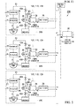
FIG. 2 is a view showing the configuration of a power generation system according to a second embodiment of the invention. -
FIG. 3 is a view showing the configuration of a power generation system according to a third embodiment of the invention. -
FIG. 4 is a view showing the configuration of a related-art power generation system. - Hereinafter, embodiments for carrying out a power generation system, and a maintenance method for a power generation system according to the invention will be described with reference to the accompanying drawings. However, the invention is not limited only to these embodiments.
- As shown in
FIG. 1 , apower generation system 20A includes aheat medium circuit 21 into which a heat medium is sent from a heat source, such as exhaust heat from vessels, factories, gas turbines, or the like, the heat of the earth, solar heat, or temperature difference between cooler deep and warmer shallow ocean waters, and amedium circuit 22 through which a medium performing heat exchange with the heat medium of theheat medium circuit 21 circulates, thereby obtaining heat energy. - Here, chlorofluocarbon media, such as HFC-134a, HFC245fa, HFO-1234yf, and HFO-1234ze, can be used as the medium of the
medium circuit 22. - The
heat medium circuit 21 supplies heat media, such as steam and water (hot water), which are obtained by recovering heat from heat sources. - The
medium circuit 22 includes acirculation pump 23, apreheater 24, anevaporator 25, a turbine (expander) 26, and acondenser 27. - The
circulation pump 23 circulates the medium within themedium circuit 22 so as to compress and send out the medium, thereby causing the medium to pass through thepreheater 24, theevaporator 25, theturbine 26, and thecondenser 27 in order. - The
preheater 24 and theevaporator 25 perform heat exchange between the heat medium of theheat medium circuit 21 and the medium of themedium circuit 22, theevaporator 25 heats and evaporates the pressurized medium through heat exchange with the heat medium (external heat source), and thepreheater 24 preheats the medium with the remaining heat of the heat medium that has passed through theevaporator 25. - The
turbine 26 rotationally drives amain shaft 26a around an axis thereof as the medium expands within a turbine chamber. A rotor (not shown) of agenerator 28 is coupled to themain shaft 26a, and the rotor (not shown) is rotationally driven while facing a stator (not shown) of thegenerator 28. Accordingly, an alternating current is output in thegenerator 28. - The alternating current output from the
generator 28 is converted into a direct current in arectifier 29, and the converted direct current is re-converted into an alternating current in asystem interconnection inverter 30 and is output to an external power grid as generated electric power. - In such a
medium circuit 22, an on-off valve (first on-off valve) 40A and an on-off valve (second on-off valve) 40B are provided on the upstream side and the downstream side of a maintenance target device, for example, theturbine 26. - Additionally, in the
medium circuit 22, aport pipe 41 is provided between the on-offvalves port pipe 41 is comminicable with themedium circuit 22, and serves as a service port (port) 42 to which a device for allowing the medium to enter or leave themedium circuit 22 is connectable. Additionally, theport pipe 41 is formed with an on-off valve (third on-off valve) 43. - The above
power generation system 20A includes acontrol unit 35. Thecontrol unit 35 controls the supply of the heat medium of theheat medium circuit 21, the operation of thecirculation pump 23 of themedium circuit 22, and the operation of the on-offvalves power generation system 20A. - Additionally, the
control unit 35 includes an operating time measuring unit 36 that measures an integrated value of the operating time of a device to be periodically maintained, for example, theturbine 26, an operating time monitoring unit 37 that monitors the integrated value of the operating time of theturbine 26 measured in the operating time measuring unit 36. - The operating time monitoring unit 37 outputs an alarm signal showing that maintenance is required if the integrated value of the operating time of the
turbine 26 reaches a predetermined specified value. Additionally, thecontrol unit 35 can similarly output an alarm signal that maintenance (checking) is required when a certain abnormality is detected in theturbine 26, in addition to the above operating time. - As the alarm signal, for example, suitable methods, such as lighting of an indicator lamp and generation of an alarm sound, may be adopted.
- On a user side of the
power generation system 20A, theturbine 26 is maintained as follows if the alarm signal is output. - In the
power generation system 20A described above, in order to maintain aturbine 26, first, the supply of the heat medium is stopped by a pump (not shown) or an on-off valve (not shown) of theheat medium circuit 21, and thecirculation pump 23 of themedium circuit 22 is stopped. - Next, the on-off
valves medium circuit 22 is shut off on the upstream side and the downstream side of theturbine 26. - Then, the on-off
valve 43 is opened after a medium recovery device 100 configured to recover the medium is connected to theservice port 42 of theport pipe 41. Accordingly, the media between the on-offvalve medium circuit 22. - After that, required maintenance can be performed for the
turbine 26. The maintenance includes, for example, replacement of seal members, checking of damage to blades, repair of damaged portions, checking and replacement of various sensors, or the like. In addition, here, the maintenance contents of theturbine 26 are not limited at all. - By connecting a vacuum pump to the
service port 42 and actuating the vacuum pump 110 after the end of the maintenance of theturbine 26, the inside of themedium circuit 22 between the on-offvalves valve 43 is closed after the vacuuming is performed up to a predetermined specified degree of vacuuming. - Then, a medium supply device 120 is connected to the
service port 42, the on-offvalve 43 is opened, and the inside of themedium circuit 22 is filled with the medium. - After the filling with the medium, the on-off
valve 43 is closed and then the on-offvalves - Accordingly, since the
power generation system 20A is brought into a restartable state, the pump (not shown) of theheat medium circuit 21 and thecirculation pump 23 of themedium circuit 22 are actuated, and thepower generation system 20A is restarted in a predetermined procedure. - According to the configuration as described above, the on-off
valves turbine 26 serving as a maintenance target in themedium circuit 22, and theservice port 42 is provided between the on-offvalves turbine 26, the on-offvalves turbine 26 between the on-offvalves medium circuit 22 may be performed. Therefore, the time taken for the extraction or vacuuming of the medium or the filling with the medium can be shortened, and the operation rate of the power generation system can be enhanced by shortening a maintenance period. Additionally, since a small amount of a medium is also required during maintenance, maintenance costs can be reduced. - Additionally, the
control unit 35 is adapted so as to measure the operating time of theturbine 26 and is adapted so as to output an alarm signal that maintenance is required when a specified operating time is reached. Therefore, maintenance can be performed for theturbine 26 at a suitable timing. - Meanwhile, in the above embodiment, the
turbine 26 has been shown as a maintenance target device. However, the invention is not limited to this. Devices other than theturbine 26 can also be targets to be maintained if the devices are devices that constitute thepower generation system 20A. In that case, the on-offvalves service port 42 may be configured so as to be provided a maintenance target device, similar to the above embodiment. - Next, a second embodiment of a power generation system and a maintenance method for a power generation system according to the invention will be described. In addition, in the second embodiment to be described below, the same components as those of the first embodiment will be designated by the same reference numerals in the drawings, and the description thereof will be omitted.
- As shown in
FIG. 2 , apower generation system 20B according to the present embodiment includes a plurality of sets ofpower generation modules - Each of the
power generation modules heat medium circuit 21, themedium circuit 22, thecirculation pump 23, thepreheater 24, theevaporator 25, theturbine 26, thecondenser 27, thegenerator 28, and therectifier 29, which are the same as components shown in the above first embodiment. - The
respective rectifiers 29 of the plurality of sets ofpower generation modules system interconnection inverter 30. - In such a
power generation system 20B, in each of thepower generation modules circulation pump 23 circulates the medium within themedium circuit 22 so as to pass through thepreheater 24, theevaporator 25, theturbine 26, and thecondenser 27 in order. Then, a gas medium that is preheated in thepreheater 24 and evaporated and gasified by theevaporator 25 expands within the turbine chamber of theturbine 26, thereby driving thegenerator 28. Thegenerator 28 outputs an alternating current, and this alternating current is converted into a direct current in therectifier 29 and is output to thesystem interconnection inverter 30. - Then, in the
system interconnection inverter 30, the direct currents output from therectifiers 29 of the plurality ofpower generation modules - In the above
power generation system 20B, in each of thepower generation modules valves turbine 26, and theport pipe 41 having theservice port 42 and the on-offvalve 43 are provided between the on-offvalves - In each of the plurality of
power generation modules control unit 35 of thepower generation system 20B controls the operation of thecirculation pump 23 of themedium circuit 22, and the operation of the on-offvalves power generation system 20A, the operating time of theturbine 26, or the like. - Such a
power generation system 20B is configured so as to selectively operate the plurality ofpower generation modules turbines 26 to be operated) to be operated and stepwisely changing the amount of power generation, in accordance with the amount of input heat energy of the heat medium sent from theheat medium circuit 21 through the control of thecontrol unit 35, or the amount of electric power required on an output side. Additionally, thecontrol unit 35 is adapted so as to preferentially stop operation from aturbine 26 having the longest operating time in the operating time monitoring unit 37 of thecontrol unit 35 when the number of modules to be operated among the plurality ofpower generation modules - In order to maintain the
turbine 26 in each of thepower generation modules heat medium circuit 21 and the circulation of the medium by thecirculation pump 23 of themedium circuit 22 are stopped in a module (for example, apower generation module 50A) equipped with aturbine 26 to be maintained among the plurality ofpower generation modules - Next, the on-off
valves valve 43 is opened after the medium recovery device 100 configured to recover the medium is connected to theservice port 42 of theport pipe 41. Accordingly, the media between the on-offvalve medium circuit 22. - After that, required maintenance can be performed for the
turbine 26. Then, by connecting the vacuum pump 110 to theservice port 42 and actuating the vacuum pump 110 after the end of the maintenance of theturbine 26, the inside of themedium circuit 22 between the on-offvalves valve 43 is closed after the vacuuming is performed up to a specified degree of vacuuming. Next, the medium supply device 120 is connected to theservice port 42, the on-offvalve 43 is opened, and the inside of themedium circuit 22 is filled with the medium. - After the filling with the medium, the on-off
valve 43 is closed and then the on-offvalves power generation module 50A for which maintenance has been performed is restarted. - According to the configuration as described above, in each of the
power generation modules valves turbine 26 serving as a maintenance target in themedium circuit 22, and theservice port 42 is provided between the on-offvalves turbine 26, the on-offvalves turbine 26 between the on-offvalves medium circuit 22 may be performed. Therefore, the time taken for the extraction or vacuuming of the medium or the filling with the medium can be shortened, and the operation rate of the power generation system can be enhanced by shortening a maintenance period. Additionally, since a small amount of a medium is also required during maintenance, maintenance costs can be reduced. - Additionally, the
control unit 35 is adapted so as to measure the operating time of theturbine 26 and is adapted to output an alarm signal that maintenance is required when a specified operating time is reached. Therefore, maintenance can be performed on theturbine 26 at a suitable timing. - Here, operation is preferentially stopped from a module equipped with a
turbine 26 having the longest operating time through the control of the operating time monitoring unit 37 of thecontrol unit 35 when the number of modules to be operated among the plurality ofpower generation modules turbine 26 can be constant, and maintenance intervals can be extended. Accordingly, maintenance can also be intensively and efficiently maintained by bringing the maintenance timings of all theturbines 26 close to each other. - Although a configuration in which the
rectifiers 29 of the plurality ofpower generation modules system interconnection inverter 30 has been adopted in the above second embodiment, the invention is not limited to this. For example, in each of the plurality ofpower generation modules rectifier 29 may include eachsystem interconnection inverter 30. - Next, a third embodiment of a power generation system and a maintenance method for a power generation system according to the invention will be described. In addition, in the third embodiment to be described below, the same components as those of the first and second embodiments will be designated by the same reference numerals in the drawings, and the description thereof will be omitted.
- As shown in
FIG. 3 , a power generation system 20C according to the present embodiment includes a plurality of sets ofpower generation modules - The power generation system 20C includes a set of the
medium circuit 22, thecirculation pump 23, thepreheater 24, theevaporator 25, and thecondenser 27 with respect to oneheat medium circuit 21. In the power generation system 20C, theheat medium circuit 21 branches into a plurality ofbranched pipes condenser 27. Thepower generation modules pipes turbine 26, thegenerator 28, and therectifier 29. - The
respective rectifiers 29 of the plurality of sets ofpower generation modules system interconnection inverter 30. - In the power generation system 20C having such a configuration, the medium sent out from the circulation pump 23 branches into the
branched pipes power generation modules preheater 24 and theevaporator 25, within themedium circuit 22. In each of thepower generation modules turbine 26 to perform power generation using thegenerator 28, and then returns to thecirculation pump 23 through thecondenser 27 in order. - Then, in the
system interconnection inverter 30, the direct currents output from therectifiers 29 of the plurality ofpower generation modules - Such a power generation system 20C, similar to the above second embodiment, is also configured so as to be able to change the number of modules to be operated among the plurality of
power generation modules heat medium circuit 21 through the control of thecontrol unit 35, or the amount of electric power required on an output side. - Additionally, the
control unit 35 is adapted so as to preferentially stop operation from a module equipped with theturbine 26 having the longest operating time when the number of modules to be operated among the plurality ofpower generation modules - In the above power generation system 20C, in each of the
power generation modules valves turbine 26. Additionally, in themedium circuit 22, theport pipe 41 equipped with theservice port 42 and the on-offvalve 43 is provided between the on-offvalves - In order to maintain the
turbine 26 in each of thepower generation modules valves power generation module 50A) equipped with aturbine 26 to be maintained among the plurality ofpower generation modules valve 43 is opened after the medium recovery device 100 configured to recover the medium is connected to theservice port 42 of theport pipe 41. Accordingly, the media between the on-offvalve - After that, required maintenance can be performed for the
turbine 26. Then, after the end of the maintenance of theturbine 26, theservice port 42 is connected to the service port 110 and thereby the inside of themedium circuit 22 between the on-offvalves valve 43 is closed. Then, the medium supply device 120 is connected to theservice port 42, the on-offvalve 43 is opened, and the inside of themedium circuit 22 is filled with the medium. - After the filling with the medium, the on-off
valve 43 is closed and then the on-offvalves power generation module 50A is restarted. - According to the configuration as described above, in each of the
power generation modules turbine 26, the on-offvalves turbine 26 between the on-offvalves medium circuit 22 may be performed. Therefore, the time taken for the extraction or vacuuming of the medium or the filling with the medium can be shortened, and the operation rate of the power generation system can be enhanced by shortening the maintenance period. Additionally, since a small amount of a medium is also required during maintenance, maintenance costs can be reduced. - Moreover, the
control unit 35 is adapted so as to preferentially stop operation from a module equipped with aturbine 26 having the longest operating time when the number of modules to be operated among the plurality ofpower generation modules turbine 26 can be constant, and maintenance intervals can be extended. Accordingly, maintenance can also be intensively and efficiently maintained by bringing the maintenance timings of all theturbines 26 close to each other. - In addition, the power generation system and the maintenance method for a power generation system in the invention are not limited to those of the above-described embodiments described with reference to the drawings, and various modification examples can be considered in the technical scope of the invention.
- For example, in the
power generation systems - Additionally, in the respective above embodiments, the
turbine 26 is shown as an expander. However, a scroll-type expander or the like can also be adopted instead of theturbine 26. - Moreover, if procedures during maintenance are within the scope of the invention, the above-mentioned procedure can be appropriately changed.
- In addition, the embodiments of the invention can be used not only when the chlorofluocarbon media are used for power generation systems but also when media, the outflow of which to the outside of systems is to be avoided from a viewpoint of environmental preservation, are used for the power generation systems.
- Additionally, the above second and third embodiments may include devices that store the operation time of a plurality of generators, and devices that display the operation time. In this case, the operation time may be displayed on display panels of power generation systems, or may be displayed on display panels outside power generation systems via the Internet. In this case, administrators or maintenance workers of the power generation systems can confirm the operation situations of respective generators and perform operation management or maintenance.
- In addition to this, the configurations mentioned in the above respective embodiments can be adopted or eliminated or can be appropriately changed to other configurations.
- According to the power generation system and the maintenance method for a power generation system, when a maintenance target device is maintained, it is not necessary to extract or vacuum the medium in the entire medium circuit. Thus, it is possible to shorten the maintenance period and enhance the operation rate of the power generation system.
-
- 20A, 20B, 20C:
- POWER GENERATION SYSTEM
- 21:
- HEAT MEDIUM CIRCUIT
- 21a, 21b, AND 21c:
- BRANCHED PIPE
- 22:
- MEDIUM CIRCUIT
- 23:
- CIRCULATION PUMP
- 24:
- PREHEATER
- 25:
- EVAPORATOR
- 26:
- TURBINE (EXPANDER)
- 26a:
- MAIN SHAFT
- 27:
- CONDENSER
- 28:
- GENERATOR
- 29:
- RECTIFIER
- 30:
- SYSTEM INTERCONNECTION INVERTER
- 35:
- CONTROL UNIT
- 36:
- OPERATING TIME MEASURING UNIT
- 37:
- OPERATING TIME MONITORING UNIT
- 40A:
- ON-OFF VALVE (FIRST ON-OFF VALVE)
- 40B:
- ON-OFF VALVE (SECOND ON-OFF VALVE)
- 41:
- PORT PIPE
- 42:
- SERVICE PORT (PORT)
- 43:
- ON-OFF VALVE (THIRD ON-OFF VALVE)
- 50A, 50B, AND 50C:
- POWER GENERATION MODULE
- 60A, 60B, AND 60C:
- POWER GENERATION MODULE
- 100:
- MEDIUM RECOVERY DEVICE
- 110:
- VACUUM PUMP
- 120:
- MEDIUM SUPPLY DEVICE
Claims (6)
- A power generation system comprising:a medium circuit through which a medium with a boiling point lower than that of water is circulated;a circulation pump configured to have the medium circulating through the medium circuit;an evaporator configured to heat the medium using heat of an external source so as to evaporate the medium;an expander configured to be driven using the medium evaporated by the evaporator;a condenser configured to condense the medium discharged from the expander;a generator configured to be driven by the expander to generate power;a first on-off valve installed on the medium circuit at an upstream side of a maintenance target device including at least one of the circulation pump, the evaporator, the expander, and the condenser, and is capable of shutting off the flow of the medium through the medium circuit;a second on-off valve installed on the medium circuit at a downstream side of the maintenance target device, and is capable of shutting off the flow of the medium through the medium circuit;a port configured to be communicable with the medium circuit between the first on-off valve and the second on-off valve; anda third on-off valve installed on the port.
- The power generation system according to Claim 1,
wherein a plurality of sets of power generation units each including the medium circuit, the circulation pump, the evaporator, the expander, the condenser, and the generator are provided in parallel, and
wherein the first on-off valve, the second on-off valve, the port, and the third on-off valve are installed on the medium circuit of each of the power generation units. - The power generation system according to Claim 1,
wherein the medium circuit branches into a plurality of branched pipes between the downstream side of the evaporator and the upstream side of the condenser, and
wherein the maintenance target device, the first on-off valve, the second on-off valve, the port, and the third on-off valve are installed on each of the branched pipes. - The power generation system according to any one of Claims 1 to 3, further comprising:an operating time measuring unit configured to measure an integrated value of the operating time of the maintenance target device, andan operating time monitoring unit configured to output a predetermined signal when the integrated value in the operating time measuring unit reaches a predetermined specified value.
- The power generation system according to Claim 4,
wherein a plurality of the maintenance target devices are provided in parallel,
wherein the power generation system further comprises a control unit that increases or reduces the number of maintenance target devices to be operated in accordance with the input from the heat source or the output from the generator, and
wherein the control unit preferentially stops the operation of the maintenance target device in which the integrated value of the operating time in the operating time measuring unit is the highest when the number of maintenance target devices to be operated is reduced. - A maintenance method for the power generation system according to any one of Claims 1 to 5, the method comprising the step of:stopping the circulation pump corresponding the maintenance target device and closing the first on-off valve on the upstream side of the maintenance target device and the second on-off valve on the downstream side of the maintenance target device;opening the third on-off valve and recovering the medium between the first on-off valve and the second on-off valve after a medium recovery device that recovers the medium is connected to the port;closing the third on-off valve after a section between the first on-off valve and the second on-off valve is vacuumed after the maintenance of the maintenance target device is completed; andconnecting a medium supply device that supplies the medium to the port, opening the third on-off valve, and filling the section between the first on-off valve and the second on-off valve with the medium from the medium supply device.
Applications Claiming Priority (2)
| Application Number | Priority Date | Filing Date | Title |
|---|---|---|---|
| JP2012288964A JP6187852B2 (en) | 2012-12-28 | 2012-12-28 | Power generation system maintenance method |
| PCT/JP2013/085114 WO2014104297A1 (en) | 2012-12-28 | 2013-12-27 | Power generation system, and maintenance method for power generation system |
Publications (3)
| Publication Number | Publication Date |
|---|---|
| EP2940259A1 true EP2940259A1 (en) | 2015-11-04 |
| EP2940259A4 EP2940259A4 (en) | 2016-11-16 |
| EP2940259B1 EP2940259B1 (en) | 2020-02-19 |
Family
ID=51021366
Family Applications (1)
| Application Number | Title | Priority Date | Filing Date |
|---|---|---|---|
| EP13869461.7A Active EP2940259B1 (en) | 2012-12-28 | 2013-12-27 | Power generation system, and maintenance method for power generation system |
Country Status (5)
| Country | Link |
|---|---|
| US (1) | US9957844B2 (en) |
| EP (1) | EP2940259B1 (en) |
| JP (1) | JP6187852B2 (en) |
| CN (1) | CN104870760B (en) |
| WO (1) | WO2014104297A1 (en) |
Cited By (1)
| Publication number | Priority date | Publication date | Assignee | Title |
|---|---|---|---|---|
| EP3447258A1 (en) * | 2017-08-25 | 2019-02-27 | Johnson Controls Technology Company | Central plant control system with equipment maintenance evaluation |
Families Citing this family (8)
| Publication number | Priority date | Publication date | Assignee | Title |
|---|---|---|---|---|
| JP6021637B2 (en) * | 2012-12-28 | 2016-11-09 | 三菱重工業株式会社 | Power generation system and power generation method |
| EP2918795B1 (en) * | 2014-03-12 | 2017-05-03 | Orcan Energy AG | Control for stacked ORC systems |
| JP6406639B2 (en) * | 2014-08-05 | 2018-10-17 | 株式会社Ihi回転機械エンジニアリング | Waste heat power generator |
| JP2016061237A (en) * | 2014-09-18 | 2016-04-25 | 株式会社Ihi | Waste-heat power generating apparatus |
| JP2017014986A (en) * | 2015-06-30 | 2017-01-19 | アネスト岩田株式会社 | Binary power generation system and binary power generation method |
| JP6640524B2 (en) * | 2015-10-16 | 2020-02-05 | パナソニック株式会社 | Rankine cycle power plant |
| JP2018031357A (en) * | 2016-08-26 | 2018-03-01 | 株式会社Ihi回転機械エンジニアリング | Binary power generation system |
| JP7491324B2 (en) * | 2022-01-13 | 2024-05-28 | 富士電機株式会社 | Beverage dispenser control device |
Family Cites Families (28)
| Publication number | Priority date | Publication date | Assignee | Title |
|---|---|---|---|---|
| JPS541741A (en) * | 1977-06-07 | 1979-01-08 | Kawasaki Heavy Ind Ltd | Turbin opening system of low boiling point medium turbine device |
| JPS5572615A (en) * | 1978-11-24 | 1980-05-31 | Agency Of Ind Science & Technol | Power generating plant |
| JPS58144613A (en) * | 1982-02-22 | 1983-08-29 | Mitsubishi Heavy Ind Ltd | Hot well tank in power plant |
| JPS595814A (en) * | 1982-07-02 | 1984-01-12 | Hitachi Ltd | Gas substituting procedure of turbine |
| JPS6453006A (en) * | 1987-08-24 | 1989-03-01 | Hitachi Ltd | Generating plant utilizing lng cooling heat and medium recovery method |
| JPH01106904A (en) * | 1987-10-19 | 1989-04-24 | Toshiba Corp | Cooling device for gland steam condenser |
| JPH01285607A (en) * | 1988-05-07 | 1989-11-16 | Hisaka Works Ltd | Hybrid binary generating system |
| US20010032109A1 (en) * | 2000-04-13 | 2001-10-18 | Gonyea Richard Jeremiah | System and method for predicting a maintenance schedule and costs for performing future service events of a product |
| JP2003302128A (en) * | 2002-04-12 | 2003-10-24 | Shinryo Corp | Method and apparatus for cleaning refrigerant piping of air conditioning refrigeration system |
| UA78460C2 (en) * | 2003-06-13 | 2007-03-15 | Kawasaki Heavy Ind Ltd | Electric power supply system |
| US7100380B2 (en) | 2004-02-03 | 2006-09-05 | United Technologies Corporation | Organic rankine cycle fluid |
| JP2005240776A (en) * | 2004-02-27 | 2005-09-08 | Central Res Inst Of Electric Power Ind | Parts operation plan creation method |
| US7331411B2 (en) * | 2004-09-23 | 2008-02-19 | Alper Shevket | Hydraulic traction system for vehicles |
| JP4829526B2 (en) | 2005-04-22 | 2011-12-07 | 株式会社荏原製作所 | Waste heat utilization system and operation method |
| JP4883935B2 (en) * | 2005-05-09 | 2012-02-22 | 株式会社荏原製作所 | Waste heat utilization system and operation method thereof |
| JP5116949B2 (en) | 2005-05-09 | 2013-01-09 | 株式会社荏原製作所 | Waste heat utilization system and operation method thereof |
| JP4738158B2 (en) | 2005-12-07 | 2011-08-03 | 三菱重工業株式会社 | Residual steam removal mechanism and residual steam removal method for steam cooling piping of gas turbine |
| US7749308B2 (en) * | 2006-01-03 | 2010-07-06 | Mccully Tim | Method for reducing hydrocarbon emissions |
| JP4726771B2 (en) * | 2006-12-08 | 2011-07-20 | 住友建機株式会社 | Hydraulic breaker hydraulic oil cleaning device |
| JP4714159B2 (en) * | 2007-01-17 | 2011-06-29 | ヤンマー株式会社 | Rankine cycle power recovery system |
| US20140265328A1 (en) * | 2008-02-25 | 2014-09-18 | Coenraad Frederik Van Blerk | Electricity generating arrangement |
| JP4835613B2 (en) * | 2008-03-04 | 2011-12-14 | 三菱電機株式会社 | Air conditioner and safety management method for air conditioner |
| US8266909B2 (en) * | 2009-04-09 | 2012-09-18 | Siemens Energy, Inc. | Air vent in main steam duct of steam turbine |
| JP5436075B2 (en) * | 2009-07-07 | 2014-03-05 | 四変テック株式会社 | Hot water system |
| US20110072819A1 (en) | 2009-09-28 | 2011-03-31 | General Electric Company | Heat recovery system based on the use of a stabilized organic rankine fluid, and related processes and devices |
| JP5155977B2 (en) | 2009-09-30 | 2013-03-06 | 三菱重工業株式会社 | Power generation system control device, power generation system, and power generation system control method |
| US8899043B2 (en) * | 2010-01-21 | 2014-12-02 | The Abell Foundation, Inc. | Ocean thermal energy conversion plant |
| JP5416729B2 (en) * | 2011-03-22 | 2014-02-12 | 株式会社日立製作所 | Water central monitoring and control device, water monitoring control system and water monitoring control program |
-
2012
- 2012-12-28 JP JP2012288964A patent/JP6187852B2/en active Active
-
2013
- 2013-12-27 US US14/652,204 patent/US9957844B2/en active Active
- 2013-12-27 CN CN201380066064.5A patent/CN104870760B/en active Active
- 2013-12-27 EP EP13869461.7A patent/EP2940259B1/en active Active
- 2013-12-27 WO PCT/JP2013/085114 patent/WO2014104297A1/en not_active Ceased
Cited By (3)
| Publication number | Priority date | Publication date | Assignee | Title |
|---|---|---|---|---|
| EP3447258A1 (en) * | 2017-08-25 | 2019-02-27 | Johnson Controls Technology Company | Central plant control system with equipment maintenance evaluation |
| US11379935B2 (en) | 2017-08-25 | 2022-07-05 | Johnson Controls Tyco IP Holdings LLP | Central plant control system with equipment maintenance evaluation |
| US11861741B2 (en) | 2017-08-25 | 2024-01-02 | Johnson Controls Tyco IP Holdings LLP | Central plant control system with equipment maintenance evaluation |
Also Published As
| Publication number | Publication date |
|---|---|
| EP2940259A4 (en) | 2016-11-16 |
| US9957844B2 (en) | 2018-05-01 |
| WO2014104297A1 (en) | 2014-07-03 |
| CN104870760A (en) | 2015-08-26 |
| JP6187852B2 (en) | 2017-08-30 |
| CN104870760B (en) | 2016-08-24 |
| EP2940259B1 (en) | 2020-02-19 |
| JP2014129800A (en) | 2014-07-10 |
| US20150330259A1 (en) | 2015-11-19 |
Similar Documents
| Publication | Publication Date | Title |
|---|---|---|
| EP2940259B1 (en) | Power generation system, and maintenance method for power generation system | |
| EP2940254B1 (en) | Power generation system and power generation method | |
| EP2940252B1 (en) | Power generation system | |
| US8739538B2 (en) | Generating energy from fluid expansion | |
| US9322300B2 (en) | Thermal cycle energy and pumping recovery system | |
| US9677414B2 (en) | Waste heat power generator | |
| US8400005B2 (en) | Generating energy from fluid expansion | |
| KR101553196B1 (en) | Power generation system of organic rankine binary cycle | |
| EP2307673A2 (en) | Cascaded condenser for multi-unit geothermal orc | |
| US20140318131A1 (en) | Heat sources for thermal cycles | |
| KR20150105162A (en) | Organic Rankin Cycle electricity generation system | |
| JP2013170553A (en) | Geothermal power generation device | |
| US20160305280A1 (en) | Steam power plant with a liquid-cooled generator | |
| US20160177955A1 (en) | Compression system | |
| KR101559728B1 (en) | Cogeneration Plant Cooling System | |
| US20110278859A1 (en) | Cooling heat generating equipment | |
| KR20150001248A (en) | Power generation system for waste heat recovery | |
| EP3580454A1 (en) | Wind turbine waste heat recovery system | |
| KR20180046699A (en) | Utilizing apparatus for heat source indirectly in binary power generation system using the egs | |
| Rai et al. | Recovery of engine waste heat using the 100-kW Class ORC “Heat Innovator” | |
| KR20100003189U (en) | Power Generation System Using Waste Heat | |
| CN107329082A (en) | A kind of electrical system and application process for ORC generating set Performance Assessments | |
| Skuratov et al. | Selecting the Startup Option for the Surgut GRES-2 800-MW Power Unit in the Absence of Its Own Steam Source | |
| JP2016037859A (en) | Waste heat generator |
Legal Events
| Date | Code | Title | Description |
|---|---|---|---|
| PUAI | Public reference made under article 153(3) epc to a published international application that has entered the european phase |
Free format text: ORIGINAL CODE: 0009012 |
|
| 17P | Request for examination filed |
Effective date: 20150618 |
|
| AK | Designated contracting states |
Kind code of ref document: A1 Designated state(s): AL AT BE BG CH CY CZ DE DK EE ES FI FR GB GR HR HU IE IS IT LI LT LU LV MC MK MT NL NO PL PT RO RS SE SI SK SM TR |
|
| AX | Request for extension of the european patent |
Extension state: BA ME |
|
| DAX | Request for extension of the european patent (deleted) | ||
| A4 | Supplementary search report drawn up and despatched |
Effective date: 20161013 |
|
| RIC1 | Information provided on ipc code assigned before grant |
Ipc: F01K 25/10 20060101AFI20161007BHEP Ipc: F01K 27/02 20060101ALI20161007BHEP Ipc: F01D 25/00 20060101ALI20161007BHEP |
|
| STAA | Information on the status of an ep patent application or granted ep patent |
Free format text: STATUS: EXAMINATION IS IN PROGRESS |
|
| 17Q | First examination report despatched |
Effective date: 20190612 |
|
| GRAP | Despatch of communication of intention to grant a patent |
Free format text: ORIGINAL CODE: EPIDOSNIGR1 |
|
| STAA | Information on the status of an ep patent application or granted ep patent |
Free format text: STATUS: GRANT OF PATENT IS INTENDED |
|
| INTG | Intention to grant announced |
Effective date: 20191119 |
|
| GRAS | Grant fee paid |
Free format text: ORIGINAL CODE: EPIDOSNIGR3 |
|
| GRAA | (expected) grant |
Free format text: ORIGINAL CODE: 0009210 |
|
| STAA | Information on the status of an ep patent application or granted ep patent |
Free format text: STATUS: THE PATENT HAS BEEN GRANTED |
|
| AK | Designated contracting states |
Kind code of ref document: B1 Designated state(s): AL AT BE BG CH CY CZ DE DK EE ES FI FR GB GR HR HU IE IS IT LI LT LU LV MC MK MT NL NO PL PT RO RS SE SI SK SM TR |
|
| REG | Reference to a national code |
Ref country code: CH Ref legal event code: EP |
|
| REG | Reference to a national code |
Ref country code: DE Ref legal event code: R096 Ref document number: 602013066050 Country of ref document: DE |
|
| REG | Reference to a national code |
Ref country code: AT Ref legal event code: REF Ref document number: 1235203 Country of ref document: AT Kind code of ref document: T Effective date: 20200315 |
|
| REG | Reference to a national code |
Ref country code: IE Ref legal event code: FG4D |
|
| REG | Reference to a national code |
Ref country code: NL Ref legal event code: MP Effective date: 20200219 |
|
| PG25 | Lapsed in a contracting state [announced via postgrant information from national office to epo] |
Ref country code: RS Free format text: LAPSE BECAUSE OF FAILURE TO SUBMIT A TRANSLATION OF THE DESCRIPTION OR TO PAY THE FEE WITHIN THE PRESCRIBED TIME-LIMIT Effective date: 20200219 Ref country code: NO Free format text: LAPSE BECAUSE OF FAILURE TO SUBMIT A TRANSLATION OF THE DESCRIPTION OR TO PAY THE FEE WITHIN THE PRESCRIBED TIME-LIMIT Effective date: 20200519 Ref country code: FI Free format text: LAPSE BECAUSE OF FAILURE TO SUBMIT A TRANSLATION OF THE DESCRIPTION OR TO PAY THE FEE WITHIN THE PRESCRIBED TIME-LIMIT Effective date: 20200219 |
|
| REG | Reference to a national code |
Ref country code: LT Ref legal event code: MG4D |
|
| PG25 | Lapsed in a contracting state [announced via postgrant information from national office to epo] |
Ref country code: BG Free format text: LAPSE BECAUSE OF FAILURE TO SUBMIT A TRANSLATION OF THE DESCRIPTION OR TO PAY THE FEE WITHIN THE PRESCRIBED TIME-LIMIT Effective date: 20200519 Ref country code: GR Free format text: LAPSE BECAUSE OF FAILURE TO SUBMIT A TRANSLATION OF THE DESCRIPTION OR TO PAY THE FEE WITHIN THE PRESCRIBED TIME-LIMIT Effective date: 20200520 Ref country code: HR Free format text: LAPSE BECAUSE OF FAILURE TO SUBMIT A TRANSLATION OF THE DESCRIPTION OR TO PAY THE FEE WITHIN THE PRESCRIBED TIME-LIMIT Effective date: 20200219 Ref country code: LV Free format text: LAPSE BECAUSE OF FAILURE TO SUBMIT A TRANSLATION OF THE DESCRIPTION OR TO PAY THE FEE WITHIN THE PRESCRIBED TIME-LIMIT Effective date: 20200219 Ref country code: IS Free format text: LAPSE BECAUSE OF FAILURE TO SUBMIT A TRANSLATION OF THE DESCRIPTION OR TO PAY THE FEE WITHIN THE PRESCRIBED TIME-LIMIT Effective date: 20200619 Ref country code: SE Free format text: LAPSE BECAUSE OF FAILURE TO SUBMIT A TRANSLATION OF THE DESCRIPTION OR TO PAY THE FEE WITHIN THE PRESCRIBED TIME-LIMIT Effective date: 20200219 |
|
| PG25 | Lapsed in a contracting state [announced via postgrant information from national office to epo] |
Ref country code: NL Free format text: LAPSE BECAUSE OF FAILURE TO SUBMIT A TRANSLATION OF THE DESCRIPTION OR TO PAY THE FEE WITHIN THE PRESCRIBED TIME-LIMIT Effective date: 20200219 |
|
| PG25 | Lapsed in a contracting state [announced via postgrant information from national office to epo] |
Ref country code: PT Free format text: LAPSE BECAUSE OF FAILURE TO SUBMIT A TRANSLATION OF THE DESCRIPTION OR TO PAY THE FEE WITHIN THE PRESCRIBED TIME-LIMIT Effective date: 20200712 Ref country code: DK Free format text: LAPSE BECAUSE OF FAILURE TO SUBMIT A TRANSLATION OF THE DESCRIPTION OR TO PAY THE FEE WITHIN THE PRESCRIBED TIME-LIMIT Effective date: 20200219 Ref country code: SK Free format text: LAPSE BECAUSE OF FAILURE TO SUBMIT A TRANSLATION OF THE DESCRIPTION OR TO PAY THE FEE WITHIN THE PRESCRIBED TIME-LIMIT Effective date: 20200219 Ref country code: SM Free format text: LAPSE BECAUSE OF FAILURE TO SUBMIT A TRANSLATION OF THE DESCRIPTION OR TO PAY THE FEE WITHIN THE PRESCRIBED TIME-LIMIT Effective date: 20200219 Ref country code: EE Free format text: LAPSE BECAUSE OF FAILURE TO SUBMIT A TRANSLATION OF THE DESCRIPTION OR TO PAY THE FEE WITHIN THE PRESCRIBED TIME-LIMIT Effective date: 20200219 Ref country code: LT Free format text: LAPSE BECAUSE OF FAILURE TO SUBMIT A TRANSLATION OF THE DESCRIPTION OR TO PAY THE FEE WITHIN THE PRESCRIBED TIME-LIMIT Effective date: 20200219 Ref country code: ES Free format text: LAPSE BECAUSE OF FAILURE TO SUBMIT A TRANSLATION OF THE DESCRIPTION OR TO PAY THE FEE WITHIN THE PRESCRIBED TIME-LIMIT Effective date: 20200219 Ref country code: CZ Free format text: LAPSE BECAUSE OF FAILURE TO SUBMIT A TRANSLATION OF THE DESCRIPTION OR TO PAY THE FEE WITHIN THE PRESCRIBED TIME-LIMIT Effective date: 20200219 Ref country code: RO Free format text: LAPSE BECAUSE OF FAILURE TO SUBMIT A TRANSLATION OF THE DESCRIPTION OR TO PAY THE FEE WITHIN THE PRESCRIBED TIME-LIMIT Effective date: 20200219 |
|
| REG | Reference to a national code |
Ref country code: AT Ref legal event code: MK05 Ref document number: 1235203 Country of ref document: AT Kind code of ref document: T Effective date: 20200219 |
|
| REG | Reference to a national code |
Ref country code: DE Ref legal event code: R097 Ref document number: 602013066050 Country of ref document: DE |
|
| PLBE | No opposition filed within time limit |
Free format text: ORIGINAL CODE: 0009261 |
|
| STAA | Information on the status of an ep patent application or granted ep patent |
Free format text: STATUS: NO OPPOSITION FILED WITHIN TIME LIMIT |
|
| 26N | No opposition filed |
Effective date: 20201120 |
|
| PG25 | Lapsed in a contracting state [announced via postgrant information from national office to epo] |
Ref country code: AT Free format text: LAPSE BECAUSE OF FAILURE TO SUBMIT A TRANSLATION OF THE DESCRIPTION OR TO PAY THE FEE WITHIN THE PRESCRIBED TIME-LIMIT Effective date: 20200219 |
|
| PG25 | Lapsed in a contracting state [announced via postgrant information from national office to epo] |
Ref country code: PL Free format text: LAPSE BECAUSE OF FAILURE TO SUBMIT A TRANSLATION OF THE DESCRIPTION OR TO PAY THE FEE WITHIN THE PRESCRIBED TIME-LIMIT Effective date: 20200219 Ref country code: SI Free format text: LAPSE BECAUSE OF FAILURE TO SUBMIT A TRANSLATION OF THE DESCRIPTION OR TO PAY THE FEE WITHIN THE PRESCRIBED TIME-LIMIT Effective date: 20200219 |
|
| REG | Reference to a national code |
Ref country code: CH Ref legal event code: PL |
|
| GBPC | Gb: european patent ceased through non-payment of renewal fee |
Effective date: 20201227 |
|
| PG25 | Lapsed in a contracting state [announced via postgrant information from national office to epo] |
Ref country code: MC Free format text: LAPSE BECAUSE OF FAILURE TO SUBMIT A TRANSLATION OF THE DESCRIPTION OR TO PAY THE FEE WITHIN THE PRESCRIBED TIME-LIMIT Effective date: 20200219 |
|
| REG | Reference to a national code |
Ref country code: BE Ref legal event code: MM Effective date: 20201231 |
|
| PG25 | Lapsed in a contracting state [announced via postgrant information from national office to epo] |
Ref country code: IE Free format text: LAPSE BECAUSE OF NON-PAYMENT OF DUE FEES Effective date: 20201227 Ref country code: LU Free format text: LAPSE BECAUSE OF NON-PAYMENT OF DUE FEES Effective date: 20201227 Ref country code: FR Free format text: LAPSE BECAUSE OF NON-PAYMENT OF DUE FEES Effective date: 20201231 |
|
| PG25 | Lapsed in a contracting state [announced via postgrant information from national office to epo] |
Ref country code: CH Free format text: LAPSE BECAUSE OF NON-PAYMENT OF DUE FEES Effective date: 20201231 Ref country code: GB Free format text: LAPSE BECAUSE OF NON-PAYMENT OF DUE FEES Effective date: 20201227 Ref country code: LI Free format text: LAPSE BECAUSE OF NON-PAYMENT OF DUE FEES Effective date: 20201231 |
|
| PG25 | Lapsed in a contracting state [announced via postgrant information from national office to epo] |
Ref country code: MT Free format text: LAPSE BECAUSE OF FAILURE TO SUBMIT A TRANSLATION OF THE DESCRIPTION OR TO PAY THE FEE WITHIN THE PRESCRIBED TIME-LIMIT Effective date: 20200219 Ref country code: CY Free format text: LAPSE BECAUSE OF FAILURE TO SUBMIT A TRANSLATION OF THE DESCRIPTION OR TO PAY THE FEE WITHIN THE PRESCRIBED TIME-LIMIT Effective date: 20200219 |
|
| PG25 | Lapsed in a contracting state [announced via postgrant information from national office to epo] |
Ref country code: MK Free format text: LAPSE BECAUSE OF FAILURE TO SUBMIT A TRANSLATION OF THE DESCRIPTION OR TO PAY THE FEE WITHIN THE PRESCRIBED TIME-LIMIT Effective date: 20200219 Ref country code: AL Free format text: LAPSE BECAUSE OF FAILURE TO SUBMIT A TRANSLATION OF THE DESCRIPTION OR TO PAY THE FEE WITHIN THE PRESCRIBED TIME-LIMIT Effective date: 20200219 |
|
| PG25 | Lapsed in a contracting state [announced via postgrant information from national office to epo] |
Ref country code: BE Free format text: LAPSE BECAUSE OF NON-PAYMENT OF DUE FEES Effective date: 20201231 |
|
| PGFP | Annual fee paid to national office [announced via postgrant information from national office to epo] |
Ref country code: DE Payment date: 20251104 Year of fee payment: 13 |
|
| PGFP | Annual fee paid to national office [announced via postgrant information from national office to epo] |
Ref country code: IT Payment date: 20251121 Year of fee payment: 13 |
|
| PGFP | Annual fee paid to national office [announced via postgrant information from national office to epo] |
Ref country code: TR Payment date: 20251225 Year of fee payment: 13 |