EP2940248B1 - Refroidissement du bord d'attaque du profil aérodynamique d'un moteur à turbine à gaz - Google Patents
Refroidissement du bord d'attaque du profil aérodynamique d'un moteur à turbine à gaz Download PDFInfo
- Publication number
- EP2940248B1 EP2940248B1 EP15158256.6A EP15158256A EP2940248B1 EP 2940248 B1 EP2940248 B1 EP 2940248B1 EP 15158256 A EP15158256 A EP 15158256A EP 2940248 B1 EP2940248 B1 EP 2940248B1
- Authority
- EP
- European Patent Office
- Prior art keywords
- airfoil
- circuit
- flow
- cooling
- gas turbine
- Prior art date
- Legal status (The legal status is an assumption and is not a legal conclusion. Google has not performed a legal analysis and makes no representation as to the accuracy of the status listed.)
- Active
Links
- 238000001816 cooling Methods 0.000 title claims description 47
- 238000000034 method Methods 0.000 claims description 4
- 238000011144 upstream manufacturing Methods 0.000 claims 1
- 230000003068 static effect Effects 0.000 description 7
- 230000007935 neutral effect Effects 0.000 description 5
- WYTGDNHDOZPMIW-RCBQFDQVSA-N alstonine Natural products C1=CC2=C3C=CC=CC3=NC2=C2N1C[C@H]1[C@H](C)OC=C(C(=O)OC)[C@H]1C2 WYTGDNHDOZPMIW-RCBQFDQVSA-N 0.000 description 3
- 238000003491 array Methods 0.000 description 3
- 238000002485 combustion reaction Methods 0.000 description 3
- 230000003044 adaptive effect Effects 0.000 description 2
- 239000000446 fuel Substances 0.000 description 2
- 238000005266 casting Methods 0.000 description 1
- 230000001419 dependent effect Effects 0.000 description 1
- 230000037406 food intake Effects 0.000 description 1
- 238000007493 shaping process Methods 0.000 description 1
Images


Classifications
-
- F—MECHANICAL ENGINEERING; LIGHTING; HEATING; WEAPONS; BLASTING
- F01—MACHINES OR ENGINES IN GENERAL; ENGINE PLANTS IN GENERAL; STEAM ENGINES
- F01D—NON-POSITIVE DISPLACEMENT MACHINES OR ENGINES, e.g. STEAM TURBINES
- F01D5/00—Blades; Blade-carrying members; Heating, heat-insulating, cooling or antivibration means on the blades or the members
- F01D5/12—Blades
- F01D5/14—Form or construction
- F01D5/18—Hollow blades, i.e. blades with cooling or heating channels or cavities; Heating, heat-insulating or cooling means on blades
- F01D5/187—Convection cooling
-
- F—MECHANICAL ENGINEERING; LIGHTING; HEATING; WEAPONS; BLASTING
- F01—MACHINES OR ENGINES IN GENERAL; ENGINE PLANTS IN GENERAL; STEAM ENGINES
- F01D—NON-POSITIVE DISPLACEMENT MACHINES OR ENGINES, e.g. STEAM TURBINES
- F01D17/00—Regulating or controlling by varying flow
- F01D17/10—Final actuators
- F01D17/12—Final actuators arranged in stator parts
- F01D17/14—Final actuators arranged in stator parts varying effective cross-sectional area of nozzles or guide conduits
- F01D17/16—Final actuators arranged in stator parts varying effective cross-sectional area of nozzles or guide conduits by means of nozzle vanes
-
- F—MECHANICAL ENGINEERING; LIGHTING; HEATING; WEAPONS; BLASTING
- F01—MACHINES OR ENGINES IN GENERAL; ENGINE PLANTS IN GENERAL; STEAM ENGINES
- F01D—NON-POSITIVE DISPLACEMENT MACHINES OR ENGINES, e.g. STEAM TURBINES
- F01D5/00—Blades; Blade-carrying members; Heating, heat-insulating, cooling or antivibration means on the blades or the members
- F01D5/12—Blades
- F01D5/14—Form or construction
- F01D5/18—Hollow blades, i.e. blades with cooling or heating channels or cavities; Heating, heat-insulating or cooling means on blades
- F01D5/186—Film cooling
-
- F—MECHANICAL ENGINEERING; LIGHTING; HEATING; WEAPONS; BLASTING
- F01—MACHINES OR ENGINES IN GENERAL; ENGINE PLANTS IN GENERAL; STEAM ENGINES
- F01D—NON-POSITIVE DISPLACEMENT MACHINES OR ENGINES, e.g. STEAM TURBINES
- F01D9/00—Stators
- F01D9/02—Nozzles; Nozzle boxes; Stator blades; Guide conduits, e.g. individual nozzles
- F01D9/04—Nozzles; Nozzle boxes; Stator blades; Guide conduits, e.g. individual nozzles forming ring or sector
- F01D9/041—Nozzles; Nozzle boxes; Stator blades; Guide conduits, e.g. individual nozzles forming ring or sector using blades
-
- F—MECHANICAL ENGINEERING; LIGHTING; HEATING; WEAPONS; BLASTING
- F01—MACHINES OR ENGINES IN GENERAL; ENGINE PLANTS IN GENERAL; STEAM ENGINES
- F01D—NON-POSITIVE DISPLACEMENT MACHINES OR ENGINES, e.g. STEAM TURBINES
- F01D5/00—Blades; Blade-carrying members; Heating, heat-insulating, cooling or antivibration means on the blades or the members
- F01D5/02—Blade-carrying members, e.g. rotors
- F01D5/08—Heating, heat-insulating or cooling means
-
- F—MECHANICAL ENGINEERING; LIGHTING; HEATING; WEAPONS; BLASTING
- F01—MACHINES OR ENGINES IN GENERAL; ENGINE PLANTS IN GENERAL; STEAM ENGINES
- F01D—NON-POSITIVE DISPLACEMENT MACHINES OR ENGINES, e.g. STEAM TURBINES
- F01D5/00—Blades; Blade-carrying members; Heating, heat-insulating, cooling or antivibration means on the blades or the members
- F01D5/12—Blades
- F01D5/14—Form or construction
- F01D5/18—Hollow blades, i.e. blades with cooling or heating channels or cavities; Heating, heat-insulating or cooling means on blades
- F01D5/187—Convection cooling
- F01D5/188—Convection cooling with an insert in the blade cavity to guide the cooling fluid, e.g. forming a separation wall
-
- F—MECHANICAL ENGINEERING; LIGHTING; HEATING; WEAPONS; BLASTING
- F05—INDEXING SCHEMES RELATING TO ENGINES OR PUMPS IN VARIOUS SUBCLASSES OF CLASSES F01-F04
- F05D—INDEXING SCHEME FOR ASPECTS RELATING TO NON-POSITIVE-DISPLACEMENT MACHINES OR ENGINES, GAS-TURBINES OR JET-PROPULSION PLANTS
- F05D2220/00—Application
- F05D2220/30—Application in turbines
- F05D2220/32—Application in turbines in gas turbines
- F05D2220/321—Application in turbines in gas turbines for a special turbine stage
- F05D2220/3212—Application in turbines in gas turbines for a special turbine stage the first stage of a turbine
-
- F—MECHANICAL ENGINEERING; LIGHTING; HEATING; WEAPONS; BLASTING
- F05—INDEXING SCHEMES RELATING TO ENGINES OR PUMPS IN VARIOUS SUBCLASSES OF CLASSES F01-F04
- F05D—INDEXING SCHEME FOR ASPECTS RELATING TO NON-POSITIVE-DISPLACEMENT MACHINES OR ENGINES, GAS-TURBINES OR JET-PROPULSION PLANTS
- F05D2240/00—Components
- F05D2240/10—Stators
- F05D2240/12—Fluid guiding means, e.g. vanes
-
- F—MECHANICAL ENGINEERING; LIGHTING; HEATING; WEAPONS; BLASTING
- F05—INDEXING SCHEMES RELATING TO ENGINES OR PUMPS IN VARIOUS SUBCLASSES OF CLASSES F01-F04
- F05D—INDEXING SCHEME FOR ASPECTS RELATING TO NON-POSITIVE-DISPLACEMENT MACHINES OR ENGINES, GAS-TURBINES OR JET-PROPULSION PLANTS
- F05D2240/00—Components
- F05D2240/20—Rotors
- F05D2240/30—Characteristics of rotor blades, i.e. of any element transforming dynamic fluid energy to or from rotational energy and being attached to a rotor
- F05D2240/303—Characteristics of rotor blades, i.e. of any element transforming dynamic fluid energy to or from rotational energy and being attached to a rotor related to the leading edge of a rotor blade
-
- F—MECHANICAL ENGINEERING; LIGHTING; HEATING; WEAPONS; BLASTING
- F05—INDEXING SCHEMES RELATING TO ENGINES OR PUMPS IN VARIOUS SUBCLASSES OF CLASSES F01-F04
- F05D—INDEXING SCHEME FOR ASPECTS RELATING TO NON-POSITIVE-DISPLACEMENT MACHINES OR ENGINES, GAS-TURBINES OR JET-PROPULSION PLANTS
- F05D2260/00—Function
- F05D2260/20—Heat transfer, e.g. cooling
- F05D2260/202—Heat transfer, e.g. cooling by film cooling
-
- Y—GENERAL TAGGING OF NEW TECHNOLOGICAL DEVELOPMENTS; GENERAL TAGGING OF CROSS-SECTIONAL TECHNOLOGIES SPANNING OVER SEVERAL SECTIONS OF THE IPC; TECHNICAL SUBJECTS COVERED BY FORMER USPC CROSS-REFERENCE ART COLLECTIONS [XRACs] AND DIGESTS
- Y02—TECHNOLOGIES OR APPLICATIONS FOR MITIGATION OR ADAPTATION AGAINST CLIMATE CHANGE
- Y02T—CLIMATE CHANGE MITIGATION TECHNOLOGIES RELATED TO TRANSPORTATION
- Y02T50/00—Aeronautics or air transport
- Y02T50/60—Efficient propulsion technologies, e.g. for aircraft
Definitions
- This disclosure relates generally to cooling within a gas turbine engine and, more particularly, to cooling leading edges of components aft variable vanes.
- Gas turbine engines are known and, typically, include a fan delivering air into a bypass duct as propulsion air and to be utilized to cool components.
- the fan also delivers air into a core engine where it is compressed in a compressor.
- the compressed air is then delivered into a combustion section where it is mixed with fuel and ignited. Products of the combustion pass downstream over turbine rotors, driving them to rotate.
- variable vanes can include variable vanes. As known, adjusting the variable vanes alters flow through the gas turbine engine and can improve overall engine performance. Adjusting variable vanes alters flow to the blades aft the variable vanes, which changes the position and characteristic shape of the stagnation point along the surface. This changes the areas of the blades having the highest heat transfer coefficients.
- actuation of the variable vanes alters the inlet angle to the downstream blades can alter the stagnation location from positive incidence (pressure side stagnation location), neutral incidence (leading edge stagnation location), to negative incidence (suction side stagnation location).
- the heat transfer coefficients located at a stagnation point of the flow over blades downstream the variable vanes can be 1.5 to 2 times greater than the heat transfer coefficients on the other portions of the blade surface.
- a prior art gas turbine engine having the features of the preamble of claim 1 is disclosed in US-5,356,265 A .
- a prior art method of improving the cooling performance of a turbine blade is disclosed in JP-S60198305 A .
- a prior art cooled aerofoil for a gas turbine engine is disclosed in EP-2236752 A2 .
- the present invention provides a gas turbine engine as recited in claim 1, and a method of cooling an airfoil as recited in claim 11.
- FIG. 1 shows an exemplary engine 10 in a schematic manner.
- a fan section 12 delivers air into a core engine 16, a radially inner bypass passage 20, and a radially outer bypass passage 24.
- a core flow C of air is delivered to the core engine 16 from the fan section 12 and moves along a core flow passage 26 extending through a compressor section 28, a combustor section 32, a turbine section 36, and then outwardly of a nozzle 40.
- Compressed air from the compressor section 28 is mixed with fuel and ignited in the combustor section 32.
- the products of combustion drive turbine rotors in the turbine section 36 to rotatably drive compressor rotors in the compressor section 28, and fan rotors 44 and 48 about an axis A.
- the fan rotor 44 supplies air to the main bypass flow B1 and the core flow C.
- the main bypass flow B1 flows through the radially inner bypass passage 20 inwardly of a main bypass flow outer housing 50, and outwardly of a core engine outer housing 58.
- the fan rotor 48 provides air to the main bypass flow B1, the core flow C, and a third stream bypass flow B2.
- the third stream bypass flow B2 flows through a radially outer bypass passage 24 that is defined inwardly of an outer housing 54 and radially outwardly of the main bypass outer housing 50.
- the example engine 10 includes an array of variable area turbine vanes 60 at an inlet to the turbine section 36 of the engine 10.
- the array 60 provides an adaptive component, which can be selectively coupled with other adaptive components of the engine 10, such as fans within the fan section 12, variable area compressor vane arrays, variable nozzles, etc.
- the vanes within the variable turbine vane array 60 are adjusted to alter flow exiting the combustor section 32 to the turbine section 36.
- the example vane array 60 is located at a first stage of the high pressure turbine within the turbine section. In another example, the array may be located elsewhere within the turbine section 36, such as at a first stage of a low pressure turbine of the turbine section.
- the turbine section 36 may include arrays of variable turbine vanes in addition to the variable turbine vane array 60. These additional arrays can be located at other stages of the high pressure turbine, the low pressure turbine, or both.
- a blade array 64 is downstream from the variable turbine vane array 60.
- the blade array 64 includes a plurality of individual blades 68 distributed annularly about the axis A.
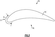
- Each blade 68 includes an airfoil 72 extending from a base 74.
- the airfoil 72 includes a suction side 76 and a pressure side 78.
- a maximum stagnation point 80 represents a point on an outer perimeter 70 of the airfoil 72 where flow C splits and moves over the suction side 76 or the pressure side 78.
- Adjusting the variable turbine vane array 60 can adjust flow to the blade 68. Varying flow to the blade 68 can change a position of the stagnation point 80.
- the stagnation point 80 can vary based on the positioning of the variable vane array 60.
- adjusting the variable vane array 60 can change the position of the stagnation point 80 associated with the blade 68.
- adjusting the variable turbine vane array 60 can change the incidence angle of flow C moving toward the variable turbine vane array 60.
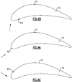
- variable turbines of array 60 When the variable turbines of array 60 are in a neutral position, the array 60 guides flow having a neutral incidence angle toward the airfoil 72. When the variable turbines of array 60 are in the neutral position, a maximum stagnation point 80 of the flow is at the position shown Figure 4A .
- Moving the variable turbines of array 60 in first direction to a position causes the flow moving toward the airfoil 72 to have a positive incidence angle, as shown in Figure 4B .
- the maximum stagnation point 80p of the flow is at the position shown in Figure 4B .
- Moving the variable turbines of array 60 in a second direction, opposite the first direction, to a position causes the flow moving toward the airfoil 72 to have a negative incidence angle, as shown in Figure 4C .
- the maximum stagnation point 80n of the flow is at the position shown in Figure 4B .
- the positive incidence angle of Figure 4B is shifted one-hundred-eighty degrees from the negative incidence angle of Figure 4C .
- the maximum stagnation point 80p of Figure 4B and the maximum stagnation point 80n of Figure 4C bound a range R of possible stagnation points 80 for flow moving across the airfoil 72 throughout one-hundred-eighty degrees of incident angle shift.
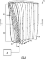
- the example blade 68 includes multiple cooling cavities on one of four separate cooling circuits.
- a first cooling cavity 82 is on a first cooling circuit.
- a second cooling cavity 84 and a third cooling cavity 86 are on a second cooling circuit.
- a fourth cooling cavity 88, a fifth cooling cavity 90, and a sixth cooling cavity 92 are on a third cooling circuit.
- a seventh cooling cavity 96 is on a fourth cooling circuit.
- first cavity 82 Since the first cavity 82 is on a separate cooling circuit from the second and third cooling cavities 84 and 86, flow moving through the first cavity 82 is not free to move to the cavities 84 or 86, and vice versa.
- both the first cavity 82 and the second cavity 84 are used to cool a leading edge area 100 of the airfoil 72.
- the leading edge area 100 is the portion of the airfoil 72 traversed by a maximum stagnation point of flow across the airfoil 72 throughout the one-hundred-eighty degrees of incident angle shift.
- Both the first circuit and the second circuit cool at least some of the airfoil 72 at the leading edge area 100.
- the first circuit cools a radially inner portion and the second circuit cools a radially outer portion.
- two circuits are used to cool the example leading edge area 100. In another example, more than two circuits are used.
- the stagnation point 80p represents a first boundary of the leading edge area 100.
- the stagnation point 80n represents an opposing section boundary of the leading edge area 100.
- the boundaries of the leading edge area 100 at the suction side 76 and pressure side 78 at a given radial section of the airfoil 72 are dictated by the maximum stagnation points when flow is moving across the airfoil in the directions of Figure 4B and 4C .
- the positions of the boundaries of the leading edge area 100 may fluctuate axially along the suction side 76 and the pressure side 78 at different radial heights of the airfoil 72.
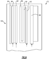
- air moves from the first cavity 82, through film holes 112, to the leading edge area 100.
- the film holes 112 are arranged in radial rows.
- the film holes 112 cover an area of the airfoil 72 spanning from the negative twenty degrees to negative sixty-five degrees away from the nominal stagnation point 80.
- the nominal stagnation point 80 is the location on the leading edge where the incidence angle into the blade has the highest aerodynamic efficiency.
- This negative range of incidence angles induce an external boundary regime in which a high pressure bubble accumulates in the region bounded by rows.
- a low pressure bubble is created.
- the independence of cooling circuits 82 and 86 ensure that hot gas does not migrate through the airfoil from the high pressure bubble to low pressure bubble.
- the second cavity 84 is an impingement cavity to convectively cool the leading edge area 100 of the airfoil 72. Air moves from the second cavity 84, through film holes 118 to the leading edge area 100.
- the film holes 118 are arranged in radial rows of showerhead holes spanning an angle of roughly twenty degrees on the suction side 76 and up to fifty degrees on the pressure side 78 of the nominal stagnation point 80.
- the number of cooling rows of film holes 112 and film holes 118 is application dependent, being added to or deleted from depending on the intended duty cycle of the overall engine 10.
- the first cavity 82 is designed such that chamber Mach numbers are kept low enough as to retain positive outflow margin from the film holes 118 during negative incidence operation. This design implementation permits an increase in the number of rows of film holes 112 without a general redesign of the internal airfoil cores or casting.
- the first cavity 82 and the film holes 112 together provide portions of a first cooling circuit within the airfoil 72.
- the first cooling circuit is separate and distinct from the second cooling circuit.
- a stage of the compressor section 28 supplies air to the first and second circuits in this example.
- the flow is provided to the first and second circuits at a radially inner end of the airfoil 72.
- the static pressures of the cavities 80, 82, and 84 of the first and second circuits have a back flow margin which allows up to 500 psia (3447 kPa) swings in external static pressure.
- Backflow margin is the ratio of internal to external pressure on an airfoil.
- the second cavity 84 and third cavity 86 may follow a serpentine cooling path.
- the second circuit is thus considered serpentine in this example.
- Other areas of the airfoil 72 may utilize a forward flowing serpentine cooling circuits that terminate aft of the cavities 80, 82, and 84 with the final flow being in the radially outward direction.
- the number of cavities within the airfoil 72 can depend on the airfoil chord length and overall operation of the engine 10. More aggressive and hotter core engines would utilize five to seven pass serpentine and conventional configurations leveraging a three pass serpentine.
- Cavities aft the second cavity 84 can be utilized to feed pressure side rows of film cooling holes, suction side rows of film cooling holes, or both. These rows can be utilized to add gross cooling to the midsides of the airfoil 72 and, as such, leverage shaping or diffusing as dictated by the external flowpath.
- the seventh cavity 96 can be a radial up flowing trailing edge feed cavity feeding a trailing edge center discharge slot.
- an apex reference line 200 extends radially along the airfoil 72.
- the apex reference line 200 represents a forwardmost point of the airfoil 72 relative to a direction of flow.
- the apex reference line 200 is within the leading edge area 100.
- Both the first circuit and the second circuit cool at least some of the airfoil 72 at the apex reference line 200.
- the first circuit cools a radially inner portion 202 and the second circuit cools a radially outer portion 204.
- Two circuits are used to cool the apex reference line in this example. In another example, more than two circuits are used.
- the present invention utilizes a multicavity design to feed a plurality of cooling holes ranging across a stagnation traverse region of an airfoil. Due to the large changes in external static pressures with the changes with incidence angle, the multicavity design leverages cavities designed with increased static outflow margin.
- the disclosed examples may result in increased engine efficiency through a robust cooling configuration that is tolerant to traverses in stagnation point and large swings in external static pressures. Further, some examples mitigate the risk of hot gas ingestion during stagnation traverse across the leading edge of the airfoil.
- the divorced cavity design ensures, in some examples, that flow redistribution due to external pressure changes does not significantly reduce section specific cooling effectiveness.
- Microchannel cooled leading edge region ensures high convective efficiency over large portion of the stagnation region.
Landscapes
- Engineering & Computer Science (AREA)
- Mechanical Engineering (AREA)
- General Engineering & Computer Science (AREA)
- Turbine Rotor Nozzle Sealing (AREA)
Claims (12)
- Moteur à turbine à gaz comprenant un composant, le composant comprenant :un profil aérodynamique (72) ayant une zone de bord d'attaque (100) ;un premier circuit pour refroidir une première section de la zone de bord d'attaque (100) ; etun second circuit pour refroidir une seconde section de la zone de bord d'attaque (100), dans lequel le premier circuit est séparé et distinct du second circuit à l'intérieur du profil aérodynamique (72), dans lequel l'écoulement à travers le profil aérodynamique (72) a un angle d'incidence par rapport au profil aérodynamique (72),caractérisé en ce que :
la zone de bord d'attaque (100) représente une zone du profil aérodynamique (72) traversée par un point de stagnation maximum (80) de l'écoulement à travers le profil aérodynamique (72) par un décalage d'angle d'incidence de cent quatre - vingts degrés. - Moteur à turbine à gaz selon la revendication 1, dans lequel le premier circuit et le second circuit sont tous deux contenus dans le profil aérodynamique (72).
- Moteur à turbine à gaz selon la revendication 1 ou 2, dans lequel le profil aérodynamique (72) est un profil aérodynamique de turbine.
- Moteur à turbine à gaz selon une quelconque revendication précédente, dans lequel le profil aérodynamique (72) a un apex avant (200) par rapport à une direction d'écoulement à travers le profil aérodynamique (72), l'apex avant (200) s'étendant radialement le long du profil aérodynamique (72) et le premier circuit et le second circuit refroidissant chacun au moins une partie du profil aérodynamique (72) au niveau de l'apex avant (200).
- Moteur à turbine à gaz selon la revendication 4, dans lequel le premier circuit est conçu pour transmettre de l'air à une partie radialement intérieure (202) de l'apex avant et le second circuit est conçu pour transmettre de l'air à une partie radialement extérieure (204) de l'apex avant (200).
- Moteur à turbine à gaz selon une quelconque revendication précédente, dans lequel le premier circuit et le second circuit sont conçus pour recevoir un écoulement à partir d'une extrémité radialement intérieure du profil aérodynamique (72).
- Moteur à turbine à gaz selon une quelconque revendication précédente, dans lequel le second circuit comprend un circuit de refroidissement en serpentin.
- Moteur à turbine à gaz selon une quelconque revendication précédente, dans lequel le profil aérodynamique (72) comprend au moins deux autres circuits de refroidissement.
- Moteur à turbine à gaz (10) selon une quelconque revendication précédente, comprenant en outre un réseau d'aubes variables (60) en amont du profil aérodynamique (72).
- Moteur à turbine à gaz (10) selon une quelconque revendication précédente, dans lequel le profil aérodynamique (72) est dans un premier étage d'une section de turbine (36).
- Procédé de refroidissement d'un profil aérodynamique (72), comprenant la transmission d'un écoulement de refroidissement à une zone de bord d'attaque (100) d'un profil aérodynamique (72) à la fois par un premier circuit de refroidissement et par un second circuit de refroidissement qui est séparé et distinct du premier circuit de refroidissement à l'intérieur du profil aérodynamique (72), dans lequel l'écoulement à travers le profil aérodynamique (72) a un angle d'incidence par rapport au profil aérodynamique (72),
caractérisé en ce que :
la zone de bord d'attaque (100) représente une zone du profil aérodynamique (72) traversée par un point de stagnation maximum (80) de l'écoulement à travers le profil aérodynamique (72) par un décalage d'angle d'incidence de cent quatre-vingts degrés. - Procédé selon la revendication 11, comprenant la transmission de l'écoulement de refroidissement provenant à la fois du premier circuit et du second circuit avec un apex avant (200) du profil aérodynamique (72), l'apex avant (200) s'étendant radialement le long du profil aérodynamique (72).
Applications Claiming Priority (1)
| Application Number | Priority Date | Filing Date | Title |
|---|---|---|---|
| US201461950301P | 2014-03-10 | 2014-03-10 |
Publications (2)
| Publication Number | Publication Date |
|---|---|
| EP2940248A1 EP2940248A1 (fr) | 2015-11-04 |
| EP2940248B1 true EP2940248B1 (fr) | 2019-07-31 |
Family
ID=52630264
Family Applications (1)
| Application Number | Title | Priority Date | Filing Date |
|---|---|---|---|
| EP15158256.6A Active EP2940248B1 (fr) | 2014-03-10 | 2015-03-09 | Refroidissement du bord d'attaque du profil aérodynamique d'un moteur à turbine à gaz |
Country Status (2)
| Country | Link |
|---|---|
| US (1) | US10329923B2 (fr) |
| EP (1) | EP2940248B1 (fr) |
Families Citing this family (14)
| Publication number | Priority date | Publication date | Assignee | Title |
|---|---|---|---|---|
| EP2949871B1 (fr) * | 2014-05-07 | 2017-03-01 | United Technologies Corporation | Segment d'aube variable |
| US10358928B2 (en) | 2016-05-10 | 2019-07-23 | General Electric Company | Airfoil with cooling circuit |
| US10415396B2 (en) | 2016-05-10 | 2019-09-17 | General Electric Company | Airfoil having cooling circuit |
| US10648341B2 (en) | 2016-11-15 | 2020-05-12 | Rolls-Royce Corporation | Airfoil leading edge impingement cooling |
| US10465526B2 (en) | 2016-11-15 | 2019-11-05 | Rolls-Royce Corporation | Dual-wall airfoil with leading edge cooling slot |
| US10577942B2 (en) * | 2016-11-17 | 2020-03-03 | General Electric Company | Double impingement slot cap assembly |
| US10450873B2 (en) * | 2017-07-31 | 2019-10-22 | Rolls-Royce Corporation | Airfoil edge cooling channels |
| CN107727258B (zh) * | 2017-09-15 | 2019-05-21 | 中国科学院工程热物理研究所 | 一种探针强化冷却结构 |
| US10443406B2 (en) | 2018-01-31 | 2019-10-15 | United Technologies Corporation | Airfoil having non-leading edge stagnation line cooling scheme |
| US10753210B2 (en) | 2018-05-02 | 2020-08-25 | Raytheon Technologies Corporation | Airfoil having improved cooling scheme |
| EP3564483A1 (fr) * | 2018-05-04 | 2019-11-06 | Siemens Aktiengesellschaft | Pale d'aube pour une aube de turbine |
| US10907479B2 (en) * | 2018-05-07 | 2021-02-02 | Raytheon Technologies Corporation | Airfoil having improved leading edge cooling scheme and damage resistance |
| US11377964B2 (en) | 2018-11-09 | 2022-07-05 | Raytheon Technologies Corporation | Airfoil with cooling passage network having arced leading edge |
| US11655828B2 (en) * | 2021-10-27 | 2023-05-23 | General Electric Company | Anti-icing systems and airfoils for a fan section of a turbine engine |
Family Cites Families (14)
| Publication number | Priority date | Publication date | Assignee | Title |
|---|---|---|---|---|
| JPH0233843B2 (ja) | 1984-03-23 | 1990-07-31 | Kogyo Gijutsuin | Gasutaabindoyokunoreikyakukozo |
| US5356265A (en) * | 1992-08-25 | 1994-10-18 | General Electric Company | Chordally bifurcated turbine blade |
| US5374162A (en) | 1993-11-30 | 1994-12-20 | United Technologies Corporation | Airfoil having coolable leading edge region |
| US5779437A (en) | 1996-10-31 | 1998-07-14 | Pratt & Whitney Canada Inc. | Cooling passages for airfoil leading edge |
| US6050777A (en) | 1997-12-17 | 2000-04-18 | United Technologies Corporation | Apparatus and method for cooling an airfoil for a gas turbine engine |
| FR2829175B1 (fr) * | 2001-08-28 | 2003-11-07 | Snecma Moteurs | Circuits de refroidissement pour aube de turbine a gaz |
| US7195458B2 (en) * | 2004-07-02 | 2007-03-27 | Siemens Power Generation, Inc. | Impingement cooling system for a turbine blade |
| US7520725B1 (en) * | 2006-08-11 | 2009-04-21 | Florida Turbine Technologies, Inc. | Turbine airfoil with near-wall leading edge multi-holes cooling |
| US7901185B2 (en) * | 2007-02-21 | 2011-03-08 | United Technologies Corporation | Variable rotor blade for gas turbine engine |
| US20090293495A1 (en) | 2008-05-29 | 2009-12-03 | General Electric Company | Turbine airfoil with metered cooling cavity |
| GB0905736D0 (en) | 2009-04-03 | 2009-05-20 | Rolls Royce Plc | Cooled aerofoil for a gas turbine engine |
| US8317473B1 (en) | 2009-09-23 | 2012-11-27 | Florida Turbine Technologies, Inc. | Turbine blade with leading edge edge cooling |
| US8562295B1 (en) * | 2010-12-20 | 2013-10-22 | Florida Turbine Technologies, Inc. | Three piece bonded thin wall cooled blade |
| EP3044416B1 (fr) | 2013-09-09 | 2020-04-22 | United Technologies Corporation | Elément de profil d'aube avec des groupes de trous de refroidissement du type pommeau de douche |
-
2015
- 2015-02-27 US US14/633,677 patent/US10329923B2/en active Active
- 2015-03-09 EP EP15158256.6A patent/EP2940248B1/fr active Active
Non-Patent Citations (1)
| Title |
|---|
| None * |
Also Published As
| Publication number | Publication date |
|---|---|
| US20160010465A1 (en) | 2016-01-14 |
| EP2940248A1 (fr) | 2015-11-04 |
| US10329923B2 (en) | 2019-06-25 |
Similar Documents
| Publication | Publication Date | Title |
|---|---|---|
| EP2940248B1 (fr) | Refroidissement du bord d'attaque du profil aérodynamique d'un moteur à turbine à gaz | |
| CA2949297A1 (fr) | Optimisation de filet de profil dynamique de turbine | |
| EP2568119B1 (fr) | Aube de turbine avec agencement de refroidissement du bord de fuite amélioré | |
| US10443398B2 (en) | Turbine blade | |
| CA2964139A1 (fr) | Profil aerodynamique pour turbine a gaz | |
| EP3165715A1 (fr) | Aube de turbine | |
| US10605170B2 (en) | Engine component with film cooling | |
| EP3208422A1 (fr) | Profil aérodynamique comportant des trous de liaison | |
| US10358928B2 (en) | Airfoil with cooling circuit | |
| US20170145831A1 (en) | Gas turbine engine with film holes | |
| US20180051566A1 (en) | Airfoil for a turbine engine with a porous tip | |
| US20190338651A1 (en) | Airfoil having cooling circuit | |
| CA2944429A1 (fr) | Pale de turbine | |
| CA2950456A1 (fr) | Refroidissement de bord de fuite d'une aube de turbine | |
| CN108691571B (zh) | 具有流动增强器的发动机部件 | |
| EP3453831B1 (fr) | Aube comportant des socles profilés | |
| US10837291B2 (en) | Turbine engine with component having a cooled tip | |
| CA2957003A1 (fr) | Insertion d'accelerateur destinee a un profil dynamique de turbine a gaz | |
| WO2017200648A2 (fr) | Surface portante à circuit de refroidissement | |
| US10731472B2 (en) | Airfoil with cooling circuit | |
| WO2018004766A1 (fr) | Profil et pale pour moteur à turbine et procédé correspondant de circulation d'un liquide de refroidissement | |
| US10508551B2 (en) | Engine component with porous trench | |
| WO2018034791A1 (fr) | Composant de moteur à section poreuse |
Legal Events
| Date | Code | Title | Description |
|---|---|---|---|
| PUAI | Public reference made under article 153(3) epc to a published international application that has entered the european phase |
Free format text: ORIGINAL CODE: 0009012 |
|
| AK | Designated contracting states |
Kind code of ref document: A1 Designated state(s): AL AT BE BG CH CY CZ DE DK EE ES FI FR GB GR HR HU IE IS IT LI LT LU LV MC MK MT NL NO PL PT RO RS SE SI SK SM TR |
|
| AX | Request for extension of the european patent |
Extension state: BA ME |
|
| 17P | Request for examination filed |
Effective date: 20160504 |
|
| RBV | Designated contracting states (corrected) |
Designated state(s): AL AT BE BG CH CY CZ DE DK EE ES FI FR GB GR HR HU IE IS IT LI LT LU LV MC MK MT NL NO PL PT RO RS SE SI SK SM TR |
|
| RAP1 | Party data changed (applicant data changed or rights of an application transferred) |
Owner name: UNITED TECHNOLOGIES CORPORATION |
|
| STAA | Information on the status of an ep patent application or granted ep patent |
Free format text: STATUS: EXAMINATION IS IN PROGRESS |
|
| 17Q | First examination report despatched |
Effective date: 20180314 |
|
| GRAP | Despatch of communication of intention to grant a patent |
Free format text: ORIGINAL CODE: EPIDOSNIGR1 |
|
| STAA | Information on the status of an ep patent application or granted ep patent |
Free format text: STATUS: GRANT OF PATENT IS INTENDED |
|
| INTG | Intention to grant announced |
Effective date: 20190207 |
|
| GRAS | Grant fee paid |
Free format text: ORIGINAL CODE: EPIDOSNIGR3 |
|
| GRAA | (expected) grant |
Free format text: ORIGINAL CODE: 0009210 |
|
| STAA | Information on the status of an ep patent application or granted ep patent |
Free format text: STATUS: THE PATENT HAS BEEN GRANTED |
|
| AK | Designated contracting states |
Kind code of ref document: B1 Designated state(s): AL AT BE BG CH CY CZ DE DK EE ES FI FR GB GR HR HU IE IS IT LI LT LU LV MC MK MT NL NO PL PT RO RS SE SI SK SM TR |
|
| REG | Reference to a national code |
Ref country code: CH Ref legal event code: EP Ref country code: GB Ref legal event code: FG4D |
|
| REG | Reference to a national code |
Ref country code: AT Ref legal event code: REF Ref document number: 1161099 Country of ref document: AT Kind code of ref document: T Effective date: 20190815 |
|
| REG | Reference to a national code |
Ref country code: IE Ref legal event code: FG4D |
|
| REG | Reference to a national code |
Ref country code: DE Ref legal event code: R096 Ref document number: 602015034640 Country of ref document: DE |
|
| REG | Reference to a national code |
Ref country code: NL Ref legal event code: MP Effective date: 20190731 |
|
| REG | Reference to a national code |
Ref country code: LT Ref legal event code: MG4D |
|
| REG | Reference to a national code |
Ref country code: AT Ref legal event code: MK05 Ref document number: 1161099 Country of ref document: AT Kind code of ref document: T Effective date: 20190731 |
|
| PG25 | Lapsed in a contracting state [announced via postgrant information from national office to epo] |
Ref country code: NO Free format text: LAPSE BECAUSE OF FAILURE TO SUBMIT A TRANSLATION OF THE DESCRIPTION OR TO PAY THE FEE WITHIN THE PRESCRIBED TIME-LIMIT Effective date: 20191031 Ref country code: SE Free format text: LAPSE BECAUSE OF FAILURE TO SUBMIT A TRANSLATION OF THE DESCRIPTION OR TO PAY THE FEE WITHIN THE PRESCRIBED TIME-LIMIT Effective date: 20190731 Ref country code: BG Free format text: LAPSE BECAUSE OF FAILURE TO SUBMIT A TRANSLATION OF THE DESCRIPTION OR TO PAY THE FEE WITHIN THE PRESCRIBED TIME-LIMIT Effective date: 20191031 Ref country code: NL Free format text: LAPSE BECAUSE OF FAILURE TO SUBMIT A TRANSLATION OF THE DESCRIPTION OR TO PAY THE FEE WITHIN THE PRESCRIBED TIME-LIMIT Effective date: 20190731 Ref country code: HR Free format text: LAPSE BECAUSE OF FAILURE TO SUBMIT A TRANSLATION OF THE DESCRIPTION OR TO PAY THE FEE WITHIN THE PRESCRIBED TIME-LIMIT Effective date: 20190731 Ref country code: LT Free format text: LAPSE BECAUSE OF FAILURE TO SUBMIT A TRANSLATION OF THE DESCRIPTION OR TO PAY THE FEE WITHIN THE PRESCRIBED TIME-LIMIT Effective date: 20190731 Ref country code: FI Free format text: LAPSE BECAUSE OF FAILURE TO SUBMIT A TRANSLATION OF THE DESCRIPTION OR TO PAY THE FEE WITHIN THE PRESCRIBED TIME-LIMIT Effective date: 20190731 Ref country code: PT Free format text: LAPSE BECAUSE OF FAILURE TO SUBMIT A TRANSLATION OF THE DESCRIPTION OR TO PAY THE FEE WITHIN THE PRESCRIBED TIME-LIMIT Effective date: 20191202 Ref country code: AT Free format text: LAPSE BECAUSE OF FAILURE TO SUBMIT A TRANSLATION OF THE DESCRIPTION OR TO PAY THE FEE WITHIN THE PRESCRIBED TIME-LIMIT Effective date: 20190731 |
|
| PG25 | Lapsed in a contracting state [announced via postgrant information from national office to epo] |
Ref country code: ES Free format text: LAPSE BECAUSE OF FAILURE TO SUBMIT A TRANSLATION OF THE DESCRIPTION OR TO PAY THE FEE WITHIN THE PRESCRIBED TIME-LIMIT Effective date: 20190731 Ref country code: GR Free format text: LAPSE BECAUSE OF FAILURE TO SUBMIT A TRANSLATION OF THE DESCRIPTION OR TO PAY THE FEE WITHIN THE PRESCRIBED TIME-LIMIT Effective date: 20191101 Ref country code: AL Free format text: LAPSE BECAUSE OF FAILURE TO SUBMIT A TRANSLATION OF THE DESCRIPTION OR TO PAY THE FEE WITHIN THE PRESCRIBED TIME-LIMIT Effective date: 20190731 Ref country code: LV Free format text: LAPSE BECAUSE OF FAILURE TO SUBMIT A TRANSLATION OF THE DESCRIPTION OR TO PAY THE FEE WITHIN THE PRESCRIBED TIME-LIMIT Effective date: 20190731 Ref country code: IS Free format text: LAPSE BECAUSE OF FAILURE TO SUBMIT A TRANSLATION OF THE DESCRIPTION OR TO PAY THE FEE WITHIN THE PRESCRIBED TIME-LIMIT Effective date: 20191130 Ref country code: RS Free format text: LAPSE BECAUSE OF FAILURE TO SUBMIT A TRANSLATION OF THE DESCRIPTION OR TO PAY THE FEE WITHIN THE PRESCRIBED TIME-LIMIT Effective date: 20190731 |
|
| PG25 | Lapsed in a contracting state [announced via postgrant information from national office to epo] |
Ref country code: TR Free format text: LAPSE BECAUSE OF FAILURE TO SUBMIT A TRANSLATION OF THE DESCRIPTION OR TO PAY THE FEE WITHIN THE PRESCRIBED TIME-LIMIT Effective date: 20190731 |
|
| PG25 | Lapsed in a contracting state [announced via postgrant information from national office to epo] |
Ref country code: IT Free format text: LAPSE BECAUSE OF FAILURE TO SUBMIT A TRANSLATION OF THE DESCRIPTION OR TO PAY THE FEE WITHIN THE PRESCRIBED TIME-LIMIT Effective date: 20190731 Ref country code: RO Free format text: LAPSE BECAUSE OF FAILURE TO SUBMIT A TRANSLATION OF THE DESCRIPTION OR TO PAY THE FEE WITHIN THE PRESCRIBED TIME-LIMIT Effective date: 20190731 Ref country code: PL Free format text: LAPSE BECAUSE OF FAILURE TO SUBMIT A TRANSLATION OF THE DESCRIPTION OR TO PAY THE FEE WITHIN THE PRESCRIBED TIME-LIMIT Effective date: 20190731 Ref country code: EE Free format text: LAPSE BECAUSE OF FAILURE TO SUBMIT A TRANSLATION OF THE DESCRIPTION OR TO PAY THE FEE WITHIN THE PRESCRIBED TIME-LIMIT Effective date: 20190731 Ref country code: DK Free format text: LAPSE BECAUSE OF FAILURE TO SUBMIT A TRANSLATION OF THE DESCRIPTION OR TO PAY THE FEE WITHIN THE PRESCRIBED TIME-LIMIT Effective date: 20190731 |
|
| PG25 | Lapsed in a contracting state [announced via postgrant information from national office to epo] |
Ref country code: IS Free format text: LAPSE BECAUSE OF FAILURE TO SUBMIT A TRANSLATION OF THE DESCRIPTION OR TO PAY THE FEE WITHIN THE PRESCRIBED TIME-LIMIT Effective date: 20200224 Ref country code: SM Free format text: LAPSE BECAUSE OF FAILURE TO SUBMIT A TRANSLATION OF THE DESCRIPTION OR TO PAY THE FEE WITHIN THE PRESCRIBED TIME-LIMIT Effective date: 20190731 Ref country code: SK Free format text: LAPSE BECAUSE OF FAILURE TO SUBMIT A TRANSLATION OF THE DESCRIPTION OR TO PAY THE FEE WITHIN THE PRESCRIBED TIME-LIMIT Effective date: 20190731 Ref country code: CZ Free format text: LAPSE BECAUSE OF FAILURE TO SUBMIT A TRANSLATION OF THE DESCRIPTION OR TO PAY THE FEE WITHIN THE PRESCRIBED TIME-LIMIT Effective date: 20190731 |
|
| REG | Reference to a national code |
Ref country code: DE Ref legal event code: R097 Ref document number: 602015034640 Country of ref document: DE |
|
| PLBE | No opposition filed within time limit |
Free format text: ORIGINAL CODE: 0009261 |
|
| STAA | Information on the status of an ep patent application or granted ep patent |
Free format text: STATUS: NO OPPOSITION FILED WITHIN TIME LIMIT |
|
| PG2D | Information on lapse in contracting state deleted |
Ref country code: IS |
|
| PG25 | Lapsed in a contracting state [announced via postgrant information from national office to epo] |
Ref country code: IS Free format text: LAPSE BECAUSE OF FAILURE TO SUBMIT A TRANSLATION OF THE DESCRIPTION OR TO PAY THE FEE WITHIN THE PRESCRIBED TIME-LIMIT Effective date: 20191030 |
|
| 26N | No opposition filed |
Effective date: 20200603 |
|
| PG25 | Lapsed in a contracting state [announced via postgrant information from national office to epo] |
Ref country code: SI Free format text: LAPSE BECAUSE OF FAILURE TO SUBMIT A TRANSLATION OF THE DESCRIPTION OR TO PAY THE FEE WITHIN THE PRESCRIBED TIME-LIMIT Effective date: 20190731 |
|
| PG25 | Lapsed in a contracting state [announced via postgrant information from national office to epo] |
Ref country code: MC Free format text: LAPSE BECAUSE OF FAILURE TO SUBMIT A TRANSLATION OF THE DESCRIPTION OR TO PAY THE FEE WITHIN THE PRESCRIBED TIME-LIMIT Effective date: 20190731 |
|
| REG | Reference to a national code |
Ref country code: CH Ref legal event code: PL |
|
| REG | Reference to a national code |
Ref country code: BE Ref legal event code: MM Effective date: 20200331 |
|
| PG25 | Lapsed in a contracting state [announced via postgrant information from national office to epo] |
Ref country code: LU Free format text: LAPSE BECAUSE OF NON-PAYMENT OF DUE FEES Effective date: 20200309 |
|
| PG25 | Lapsed in a contracting state [announced via postgrant information from national office to epo] |
Ref country code: CH Free format text: LAPSE BECAUSE OF NON-PAYMENT OF DUE FEES Effective date: 20200331 Ref country code: LI Free format text: LAPSE BECAUSE OF NON-PAYMENT OF DUE FEES Effective date: 20200331 Ref country code: IE Free format text: LAPSE BECAUSE OF NON-PAYMENT OF DUE FEES Effective date: 20200309 |
|
| PG25 | Lapsed in a contracting state [announced via postgrant information from national office to epo] |
Ref country code: BE Free format text: LAPSE BECAUSE OF NON-PAYMENT OF DUE FEES Effective date: 20200331 |
|
| PG25 | Lapsed in a contracting state [announced via postgrant information from national office to epo] |
Ref country code: MT Free format text: LAPSE BECAUSE OF FAILURE TO SUBMIT A TRANSLATION OF THE DESCRIPTION OR TO PAY THE FEE WITHIN THE PRESCRIBED TIME-LIMIT Effective date: 20190731 Ref country code: CY Free format text: LAPSE BECAUSE OF FAILURE TO SUBMIT A TRANSLATION OF THE DESCRIPTION OR TO PAY THE FEE WITHIN THE PRESCRIBED TIME-LIMIT Effective date: 20190731 |
|
| PG25 | Lapsed in a contracting state [announced via postgrant information from national office to epo] |
Ref country code: MK Free format text: LAPSE BECAUSE OF FAILURE TO SUBMIT A TRANSLATION OF THE DESCRIPTION OR TO PAY THE FEE WITHIN THE PRESCRIBED TIME-LIMIT Effective date: 20190731 |
|
| REG | Reference to a national code |
Ref country code: DE Ref legal event code: R081 Ref document number: 602015034640 Country of ref document: DE Owner name: RAYTHEON TECHNOLOGIES CORPORATION (N.D.GES.D.S, US Free format text: FORMER OWNER: UNITED TECHNOLOGIES CORPORATION, FARMINGTON, CONN., US |
|
| PGFP | Annual fee paid to national office [announced via postgrant information from national office to epo] |
Ref country code: FR Payment date: 20230222 Year of fee payment: 9 |
|
| PGFP | Annual fee paid to national office [announced via postgrant information from national office to epo] |
Ref country code: GB Payment date: 20230223 Year of fee payment: 9 Ref country code: DE Payment date: 20230221 Year of fee payment: 9 |
|
| P01 | Opt-out of the competence of the unified patent court (upc) registered |
Effective date: 20230520 |
|
| PGFP | Annual fee paid to national office [announced via postgrant information from national office to epo] |
Ref country code: DE Payment date: 20240220 Year of fee payment: 10 Ref country code: GB Payment date: 20240220 Year of fee payment: 10 |