EP2940200B1 - Industrial double-layered fabric - Google Patents
Industrial double-layered fabric Download PDFInfo
- Publication number
- EP2940200B1 EP2940200B1 EP13867530.1A EP13867530A EP2940200B1 EP 2940200 B1 EP2940200 B1 EP 2940200B1 EP 13867530 A EP13867530 A EP 13867530A EP 2940200 B1 EP2940200 B1 EP 2940200B1
- Authority
- EP
- European Patent Office
- Prior art keywords
- surface side
- warp
- woven
- fabric
- yarn
- Prior art date
- Legal status (The legal status is an assumption and is not a legal conclusion. Google has not performed a legal analysis and makes no representation as to the accuracy of the status listed.)
- Active
Links
Images




Classifications
-
- D—TEXTILES; PAPER
- D03—WEAVING
- D03D—WOVEN FABRICS; METHODS OF WEAVING; LOOMS
- D03D1/00—Woven fabrics designed to make specified articles
-
- D—TEXTILES; PAPER
- D03—WEAVING
- D03D—WOVEN FABRICS; METHODS OF WEAVING; LOOMS
- D03D11/00—Double or multi-ply fabrics not otherwise provided for
-
- D—TEXTILES; PAPER
- D21—PAPER-MAKING; PRODUCTION OF CELLULOSE
- D21F—PAPER-MAKING MACHINES; METHODS OF PRODUCING PAPER THEREON
- D21F1/00—Wet end of machines for making continuous webs of paper
- D21F1/0027—Screen-cloths
- D21F1/0036—Multi-layer screen-cloths
- D21F1/0045—Triple layer fabrics
-
- D—TEXTILES; PAPER
- D21—PAPER-MAKING; PRODUCTION OF CELLULOSE
- D21F—PAPER-MAKING MACHINES; METHODS OF PRODUCING PAPER THEREON
- D21F1/00—Wet end of machines for making continuous webs of paper
- D21F1/0027—Screen-cloths
- D21F1/0054—Seams thereof
-
- Y—GENERAL TAGGING OF NEW TECHNOLOGICAL DEVELOPMENTS; GENERAL TAGGING OF CROSS-SECTIONAL TECHNOLOGIES SPANNING OVER SEVERAL SECTIONS OF THE IPC; TECHNICAL SUBJECTS COVERED BY FORMER USPC CROSS-REFERENCE ART COLLECTIONS [XRACs] AND DIGESTS
- Y10—TECHNICAL SUBJECTS COVERED BY FORMER USPC
- Y10T—TECHNICAL SUBJECTS COVERED BY FORMER US CLASSIFICATION
- Y10T442/00—Fabric [woven, knitted, or nonwoven textile or cloth, etc.]
- Y10T442/30—Woven fabric [i.e., woven strand or strip material]
- Y10T442/3179—Woven fabric is characterized by a particular or differential weave other than fabric in which the strand denier or warp/weft pick count is specified
Definitions
- the present invention relates to a structure of a joint loop in an industrial two-layer fabric, in particular, relates to the structure of the joint loop in the industrial two-layer fabric using warp fabric yarn-contact binding yarns.
- Fabrics obtained by weaving warps and wefts have conventionally been used widely as an industrial fabric. They are, for example, used in various fields including papermaking fabrics such as papermaking canvases, non-woven cloth making fabric, sludge hydrating fabric, building material making belts and conveyer belts.
- the applicant developed the two-layer fabric of yarn-contact binding yarn type without independent binding yarns (refer to Patent Publication 1).
- the above industrial fabric has to be processed to be in an endless form to be used with being mounted on machines such as a papermaking machine, a hydrating machine, etc.
- a so-called weave patching method a method in which each of loops is formed at the both ends of the industrial fabric itself by using its warps to be aligned with each other, and then a joint wire core is introduced into holes of the loops, a method in which the joint wire core is introduced after spiral loops are arranged at both ends of the fabric so as to be aligned with each other, and a method in which the joint wire core is introduced after so-called clipper racing which is a metal hook is mounted on both ends of the fabric are publicly known (refer to Patent Publications 2,3 and 4).These well-known methods are adopted in accordance with an application.
- each of loops is formed at the both ends of the industrial fabric itself by using its warps to be aligned with each other
- the fabric can be freely formed to be an endless form or so as to have ends
- the fabric can be formed to be an endless form with being wound around a machine after the fabric with ends is wound between rolls of the machine, in a case where the fabric is mounted on the machine, which enables the fabric to be readily and efficiently mounted on the machine.
- one end of a new industrial fabric is connected to the one end of after the old industrial fabric which has been used for a long time is formed so as to have ends with being mounted on the machine, and then, the machine can be operated.
- the machine can be operated.
- the old industrial fabric is removed and the new industrial fabric can be formed to be an endless form so as to be mounted on the machine.
- a cantilever method In case of the method of the patching in a weaving form in which it is impossible to freely form the industrial two-layer fabric in an endless form or the one with ends, so-called a cantilever method is needed.
- the rolls of the machine are supported at its one side, and the industrial fabric is introduced from the one side of the machine in the widthwise direction to be wound around after pillars, etc. which hinders such an introduction at the other side are removed.
- a special structure for removing the fabric is needed for the machine itself in order to carry out the method of the patching in a weaving form under the cantilever method, so that the cost for manufacturing the machine has to be increased.
- US 5,769,131 discloses an on-machine-seamable papermakers' fabric having a smooth surface and a prolonged life includes flat machine-direction yarns which define the upper and lower surfaces thereof.
- the fabric has two layers of cross-machine direction yarns, each of which is interwoven with the flat machine-direction yarns.
- Other machine-direction yarns, of round cross section weave with the cross-machine-direction yarns in the two layers to bind the two layers together.
- the knuckles of these round machine-direction yarns are within the fabric with respect to the planes defined by the flat machine-direction yarns, and, and a consequence, are less susceptible to degradation by heat and abrasion.
- the papermakers' fabric is seamed into endless form during installation on a paper machine.
- seaming loops are formed by the round machine-direction yarns.
- seaming loops are formed by the flat machine-direction yarns. The seaming loops are interdigitated with one another when the two ends of the fabric are brought together during installation on the paper machine, defining a passage through which a seaming pin or pintle may be directed to join the two ends to one another.
- the object of the present invention is to form a joint loop structure using warps which form a surface of an industrial two-layer fabric of the contact-yarn binding type without independent binding yarns, at its both ends.
- the industrial two-layer fabric of the present invention forms a joint loop structure using warps at its both ends of the contact-yarn binding type without independent binding yarns, it has following technical features.
- a joint loop structure using warps which form a surface of the industrial two-layer fabric of the contact-yarn binding type without independent binding yarns can be formed at its both ends.
- the two-layer fabric of the present invention is the one which includes at least one upper surface side fabric constituted by upper surface side warps and upper surface side wefts, at least one lower surface side fabric constituted by lower surface side warps and lower surface side wefts, and binding weft yarns each of which binds the upper surface side fabric and the lower surface side fabric.
- the warp fabric yarn-contact binding yarn in the present invention is not just a yarn which functions to bind the upper surface side fabric and the lower surface side fabric, and is defined to be a yarn which functions not only to bind the upper surface side fabric and the lower surface side fabric, but also to cooperate with the upper surface side warp to form the surface structure on the upper surface side fabric.
- the upper surface side warp serving as the warp fabric yarn-contact binding yarn is not woven into the upper surface side weft at one or more points of a complete structure, and extends toward the lower surface side instead and is woven into the lower surface side weft at the lower surface side, and then, extends toward the upper surface sides to be woven into other upper surface side weft, while, the lower surface side warp is not woven into the lower surface side weft at a point where the upper surface side warp serving as the warp fabric yarn-contact binding yarn is woven into the lower surface side weft at the lower surface side, and extends toward the upper surface side instead to be woven into the upper surface side weft which is not woven into the upper surface side warp, at the upper surface side, and then extends toward the lower surface side to be woven into other lower surface side weft.
- the upper surface side structure and the lower surface side structure can be prevented from being collapsed, and good wire mark properties can be obtained.
- the yarn which functions as the binding yarn is a contact-yarn constituting the fabric structure and is a warp which is constantly tensioned during its use, as compared with the binding yarn of the weft, the very strong binding force which adheres the upper surface side fabric to the lower surface side fabric is always applied, so that a good adhesive properties are obtained.
- the binding force can be prevented from being weakened due to the fact that the binding yarn is rubbed between the upper and lower surface side fabrics to cause an inner wear, or the clearance between the upper and lower surface side fabrics can be prevented from being generated, or the upper and lower surface side fabrics can be prevented from being separated.
- the upper and lower surface side fabrics are bound by the upper and lower warp fabric yarn-contact binding yarns, the adhesive properties can be further improved.
- a joint loop is formed by turning back at least a portion of the warp at the both ends in the longitudinal direction of the fabric which corresponds to the direction in which the belt advances. Since the longitudinal yarn in the complete structure forms the joint loop, the turned back warp and the warp opposite to the turned back warp form a pair.
- the number of the knuckles of one of the warps forming the pair is the same as that of the other of the warps forming the pair, in the longitudinal structure, and the shapes of the knuckles are substantially same, and the distance between the knuckles are substantially same.
- the phrase of " shapes of the knuckles are substantially same" includes a case where the shapes of the knuckles are completely same in a physical sense. For example, in a case where one of the warps forming a pair passes over three upper surface side wefts to pass below one lower surface side weft, while the other of the warps passes over three upper surface side wefts to pass below one lower surface side weft, this situation corresponds to " shapes of the knuckles are substantially same ".
- the phrase of " a distance between the knuckles are substantially same" also includes a case where the distance between the knuckles are completely same in a physical sense.
- the density related to the number of yarns relative to the upper surface side fabric can be set to be the same as that of the upper surface side fabric, or 1/2, 2/3, for example, of the density of upper surface side fabric.
- a yarn to be used in the present invention can be selected freely depending on the properties which an industrial fabric is desired to have. Examples of it include, in addition to monofilaments, multifilaments, spun yarns, finished yarns subjected to crimping or bulking such as so-called textured yarn, bulky yarn and stretch yarn, and yarns obtained by intertwining them.
- As the cross-section of the yarn not only circular form but also square or short form such as stellar form, or elliptical or hollow form can be used.
- the material of the yarn can be selected freely and usable examples of it include polyester, polyamide, polyphenylene sulfide, polyvinylidene fluoride, polypropylene, aramid, polyether ketone, polyethylene naphthalate, polytetrafluoroethylene, cotton, wool and metal.
- polyester polyamide
- polyphenylene sulfide polyvinylidene fluoride
- polypropylene polypropylene
- aramid polyether ketone
- polyethylene naphthalate polytetrafluoroethylene
- lower surface side warps, lower surface side warps, and upper surface side wefts use of a polyester monofilament having rigidity and excellent dimensional stability is usually preferred.
- lower surface side wefts which need wear resistance are obtained by interweaving of polyester monofilaments and polyamide monofilaments while arranging them alternately, they are able to have wear resistance without losing rigidity.
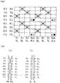
- Fig.1 is a design view showing a complete structure of a first embodiment of the present invention.
- the design view corresponds to the complete structure of the fabric defining the minimum unit to be repeated of the fabric structure.
- the fabric recited in the claims corresponds to this complete structure.
- the final product is completed by combining any number of such complete structures in the longitudinal direction and the direction perpendicular to the longitudinal direction.
- the warp is indicated by a reference number such as 1,2,3 .
- the upper and lower warps are indicated by the reference number to which U and L are attached, respectively.
- the weft is indicated by a reference number such as 1',2' ,3' .
- the upper surface side weft and the lower surface side weft are indicated by the reference number to which U and L are attached, respectively, such as 1'U, 2'L, etc.
- the binding weft yarn and the auxiliary weft are indicated by the reference number to which b is attached, respectively, such as 1'U, 1'L, 4Ub, 4Lb, etc.
- the warp serving as the binding yarn is indicated by adding b, 1Ub, 2Lb, for instance.
- a symbol “ ⁇ ” indicates that the upper surface side warp is arranged above the upper surface side weft or the auxiliary weft, and a symbol “ ⁇ ” indicates that the lower surface side warp is arranged below the lower surface side weft.
- a solid triangle symbol “ ⁇ ” indicates that the lower surface side warp serving as the binding weft yarn is arranged above the upper surface side weft.
- a triangle symbol “ ⁇ ” indicates that the upper surface side warp serving as the warp fabric yarn-contact binding yarn is arranged below the lower surface side weft.
- a solid square symbol “ ⁇ ” indicates that the lower surface side warp serving as the warp fabric yarn-contact binding yarn is arranged above the upper surface side weft.
- a square symbol “ ⁇ ” indicates that the lower surface side warp serving as the warp fabric yarn-contact binding yarn is arranged below the lower surface side weft
- Figs.1 and 2 are a design view and a cross section view showing an industrial two-layer fabric according to the first embodiment, respectively.
- the two-layer fabric of the first embodiment includes upper surface side warps (1U,2U,3U,5U,6U,7U), lower surface side warps (1L,2L,3L,5L,6L,7L), upper surface side warps 4Ub, 8Ub each serving as a warp fabric yarn-contact binding yarn, and lower surface side warps 4Lb, 8Lb each serving as a warp fabric yarn-contact binding yarn to form eight shafts.
- a ratio of the upper surface side wefts (1'U,2'U%) to the lower surface side wefts (1'L, 2'L%) is 1/1.
- the upper surface side warp (4Ub) serving as the warp fabric yarn-contact binding yarn is not woven into the upper surface side weft at one point (4'U, 5'U,6'U) of a complete structure into which an upper surface side warp would be essentially woven, and extends toward the lower surface side instead and is woven into the lower surface side weft (5'L) at the lower surface side, and then, extends toward the upper surface side to be woven into other upper surface side weft.
- the lower surface side warp (4Lb) is not woven into the lower surface side weft (5'L) at the point where the upper surface side warp (4Ub) serving as the warp fabric yarn-contact binding yarn is woven into the lower surface side weft (5'L) at the lower surface side, and extends toward the upper surface side instead to be woven into the upper surface side wefts (4'U, 5'U,6'U) into which the upper surface side warp (4Ub) is not woven into, at the upper surface side, and then extends toward the lower surface side to be woven into other lower surface side weft.
- the upper surface side warp (5U) is woven into the upper surface side wefts (1'U, 3'U, 4'U, 5'U, 7'U, 8'U) at two points on the upper surface side
- the lower surface side warp (5L) is woven into the lower surface side wefts (4'L, 8'L) at two points on the lower surface side.
- a joint loop (not shown) is formed by at least one end portion of the warp being turned back at both end portions in its longitudinal direction.
- the warps forming a pair are constituted by the upper surface side warp and the lower surface side warp, and the warp fabric yarn-contact binding yarns.
- the number of the knuckles of the turned back warp is the same as those of the warp opposite to the turned back warp to form a pair, and distances between the knuckles of the turned back warp are substantially the same as those of the warp opposite to the turned back warp to form a pair, in a longitudinal structure.
- the joint loop using the warp can be formed at the both end portions of the industrial two-layer fabric of the contact-yarn binding type at which the conventional joint loop could not be formed.
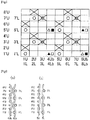
- Figs.3 and 4 are a design view and a cross section view showing an industrial two-layer fabric according to the second embodiment, respectively.
- the two-layer fabric of the second embodiment includes upper surface side warps (1U,2U,3U,5U,6U,7U), lower surface side warps (1L,2L,3L,5L,6L,7L), upper surface side warps 4Ub, 8Ub each serving as a warp fabric yarn-contact binding yarn, and lower surface side warps 4Lb, 8Lb each serving as a warp fabric yarn-contact binding yarn to form eight shafts.
- a ratio of the upper surface side wefts (1'U,2'U%) to the lower surface side wefts (1'L, 2'L%) is 1/1.
- the upper surface side warp (4Ub) serving as the warp fabric yarn-contact binding yarn is not woven into the upper surface side weft at one point (5'U) of a complete structure into which an upper surface side warp would be essentially woven, and extends toward the lower surface side instead and is woven into the lower surface side weft (5'L) at the lower surface side, and then, extends toward the upper surface side to be woven into other upper surface side weft.
- the lower surface side warp (4Lb) is not woven into the lower surface side weft (5'L) at the point where the upper surface side warp (4Ub) serving as the warp fabric yarn-contact binding yarn is woven into the lower surface side weft (5'L) at the lower surface side, and extends toward the upper surface side instead to be woven into the upper surface side wefts (5'U) into which the upper surface side warp (4Ub) is not woven into, at the upper surface side, and then extends toward the lower surface side to be woven into other lower surface side weft.
- the upper surface side warp (5U) is woven into the upper surface side wefts (2'U, 6'U) at two points on the upper surface side
- the lower surface side warp (5L) is woven into the lower surface side wefts (2'L, 6'L) at two points on the lower surface side.
- a joint loop (not shown) is formed by at least one end portion of the warp being turned back at both end portions in its longitudinal direction.
- the warps forming a pair are constituted by the upper surface side warp and the lower surface side warp, and the warp fabric yarn-contact binding yarns.
- the number of the knuckles of the turned back warp is the same as those of the warp opposite to the turned back warp to form a pair, and distances between the knuckles of the turned back warp are substantially the same as those of the warp opposite to the turned back warp to form a pair, in a longitudinal structure.
- the joint loop using the warp can be formed at the both end portions of the industrial two-layer fabric of the contact-yarn binding type at which the conventional joint loop could not be formed.
- Figs.5 and 6 are a design view and a cross section view showing an industrial two-layer fabric according to the third embodiment, respectively.
- the two-layer fabric of the third embodiment includes upper surface side warps (1U,2U,3U,5U,6U,7U), lower surface side warps (1L,2L,3L,5L,6L,7L), upper surface side warps 4Ub, 8Ub each serving as a warp fabric yarn-contact binding yarn, and lower surface side warps 4Lb, 8Lb each serving as a warp fabric yarn-contact binding yarn to form eight shafts.
- a ratio of the upper surface side wefts (1'U,2'U%) to the lower surface side wefts (1'L, 2'L%) is 2/1.
- the upper surface side warp (4Ub) serving as the warp fabric yarn-contact binding yarn is not woven into the upper surface side weft at one point (5'U) of a complete structure into which an upper surface side warp would be essentially woven, and extends toward the lower surface side instead and is woven into the lower surface side weft (5'L) at the lower surface side, and then, extends toward the upper surface side to be woven into other upper surface side weft.
- the lower surface side warp (4Lb) is not woven into the lower surface side weft (5'L) at the point where the upper surface side warp (4Ub) serving as the warp fabric yarn-contact binding yarn is woven into the lower surface side weft (5'L) at the lower surface side, and extends toward the upper surface side instead to be woven into the upper surface side wefts (5'U) into which the upper surface side warp (4Ub) is not woven into, at the upper surface side, and then extends toward the lower surface side to be woven into other lower surface side weft.
- the upper surface side warp (5U) is woven into the upper surface side wefts (2'U, 6'U) at two points on the upper surface side
- the lower surface side warp (5L) is woven into the lower surface side wefts (1'L, 5'L) at two points on the lower surface side.
- a joint loop (not shown) is formed by at least one end portion of the warp being turned back at both end portions in its longitudinal direction.
- the warps forming a pair are constituted by the upper surface side warp and the lower surface side warp, and the warp fabric yarn-contact binding yarns.
- the number of the knuckles of the turned back warp is the same as those of the warp opposite to the turned back warp to form a pair, and distances between the knuckles of the turned back warp are substantially the same as those of the warp opposite to the turned back warp to form a pair, in a longitudinal structure.
- the joint loop using the warp can be formed at the both end portions of the industrial two-layer fabric of the contact-yarn binding type at which the conventional joint loop could not be formed.
- Figs.7 to 11 are a design view and a cross section view showing an industrial two-layer fabric according to the fourth embodiment, respectively.
- the two-layer fabric of the fourth embodiment includes upper surface side warps (2U,4U,6U,8U), lower surface side warps (2L,4L,6L,8L), upper surface side warps lUb,3Ub,5Ub,7Ub each serving as a warp fabric yarn-contact binding yarn, and lower surface side warps lLb,3Lb,5Lb,7Lb each serving as a warp fabric yarn-contact binding yarn to form eight shafts.
- a ratio of the upper surface side wefts (1'U, 2'U%) to the lower surface side wefts (1'L, 2'L%) is 2/1.
- the upper surface side warp (1Ub) serving as the warp fabric yarn-contact binding yarn is not woven into the upper surface side weft at one point (5'U,6'U) of a complete structure into which an upper surface side warp would be essentially woven, and extends toward the lower surface side instead and is woven into the lower surface side weft (5'L) at the lower surface side, and then, extends toward the upper surface side to be woven into other upper surface side weft.
- the lower surface side warp (1Lb) is not woven into the lower surface side weft (5'L) at the point where the upper surface side warp (1Ub) serving as the warp fabric yarn-contact binding yarn is woven into the lower surface side weft (5'L) at the lower surface side, and extends toward the upper surface side instead to be woven into the upper surface side wefts (5'U, 6'U) into which the upper surface side warp (1Ub) is not woven into, at the upper surface side, and then extends toward the lower surface side to be woven into other lower surface side weft.
- the upper surface side warp (2U) is woven into the upper surface side wefts (3'U, 4'U,7'U, 8'U) at two points on the upper surface side, while the lower surface side warp (2L) is woven into the lower surface side wefts (3'U, 7'U) at two points on the lower surface side.
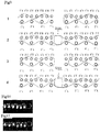
- Fig.9 is a conceptual cross section of both end portions of the industrial two-layer fabric according to the fourth embodiment.
- a point 1 of the warp fabric yarn-contact binding yarn by 1Ub and 1Lb a point 2 of the warp by 2U and 2L, a point 3 of the warp fabric yarn-contact binding yarn by 3Ub and 3Lb, and a point 4 of the warp by 4U and 4L are illustrated, from the above in order.
- the upper surface side warp 1U serving as warp fabric yarn-contact binding yarn is turned back at the upper surface side weft 6'U to be woven into the lower surface side weft 5'L on the lower surface side into which the lower surface side warp 1Lb serving as warp fabric yarn-contact binding yarn would be woven otherwise, and then, is woven into the upper surface side wefts 2'U,1'U on the upper surface side.
- the smooth surface can be maintained by turning back the upper surface side warp to be woven into the portion into which the lower surface side warp would be woven.
- the upper surface side warp 2U forms the joint loop WSBL and is turned back to be woven into the lower surface side weft 7'L on the lower surface side into which the lower surface side warp 2L would be woven otherwise, and then, is woven into the lower surface side weft 3'L on the lower surface side.
- the upper surface side warp 2U forms the joint loop WSBL and is turned back to be woven into the lower surface side wefts 3'L,7'L on the lower surface side into which the lower surface side warp 2L would be woven otherwise.
- the upper surface side warp 3Ub serving as warp fabric yarn-contact binding yarn and is woven into the upper surface side wefts 6'U, 7'U on the upper surface side to form a stop, and then, is woven into the upper surface side wefts 3'U, 2'U on the upper surface side.
- the upper surface side warp 4U forms the joint loop WSBL and is turned back to be woven into the lower surface side wefts 5'U, 1'U on the lower surface side into which the lower surface side warp 4L would be woven otherwise.
- a longitudinal yarn in the complete structure forms the joint loop WSBL, it includes a warp opposite to the turned back warp forming a pair.
- the number of the knuckles in the longitudinal structure of one of the warps forming the pair is the same as that of the other of the warps forming the pair, and distances between the knuckles of one of the warps forming the pair are the same as those of the other of the warps forming the pair.
- the joint loop structure using warps on the both end portions of the industrial two-layer fabric of the contact-yarn binding type can be formed which was difficult in the conventional joint loop structure.
- Fig. 10 is a photograph of a longitudinal cross section of the third upper point 3 in Fig.9.
- Fig. 10 shows that the stop is formed by the upper surface side warp 3Ub serving as warp fabric yarn-contact binding yarn, and that the lower surface side warp 2L forms the loop at the back.
- Fig. 11 is a photograph of a longitudinal cross section of the fourth upper point 4 in Fig.9.
- Fig.11 shows that the upper surface side warp 4U forms the joint loop WSBL to be turned back and is woven into the lower surface side wefts 5'U, 1'U on the lower surface side.
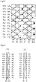
- Figs.12 and 13 are a design view and a cross section view showing an industrial two-layer fabric according to the fifth embodiment, respectively.
- the two-layer fabric of the fifth embodiment includes upper surface side warps (1U,2U,4U,5U), lower surface side warps (1L,2L,4L,5L), upper surface side warps 3Ub, 6Ub each serving as a warp fabric yarn-contact binding yarn, and lower surface side warps 3Lb, 6Lb each serving as a warp fabric yarn-contact binding yarn to form eight shafts.
- a ratio of the upper surface side wefts (1'U,2'U%) to the lower surface side wefts (1'L, 2'L%) is 1/1
- the upper surface side warp (3Ub) serving as the warp fabric yarn-contact binding yarn is not woven into the upper surface side weft at one point (7'U, 9'U,11'U) of a complete structure into which an upper surface side warp would be essentially woven, and extends toward the lower surface side instead and is woven into the lower surface side weft (9'L) at the lower surface side, and then, extends toward the upper surface side to be woven into other upper surface side weft.
- the lower surface side warp (3Lb) is not woven into the lower surface side weft (5'L) at the point where the upper surface side warp (3Ub) serving as the warp fabric yarn-contact binding yarn is woven into the lower surface side weft (5'L) at the lower surface side, and extends toward the upper surface side instead to be woven into the upper surface side wefts (7'U,9'U,11'U) into which the upper surface side warp (3Ub) is not woven into, at the upper surface side, and then extends toward the lower surface side to be woven into other lower surface side weft.
- the upper surface side warp (4U) is woven in a plain weave, while the lower surface side warp (4L) is woven into the lower surface side wefts (6'L, 12'L) at two points on the lower surface side.
- a joint loop (not shown) is formed by at least one end portion of the warp being turned back at both end portions in its longitudinal direction.
- the warps forming a pair are constituted by the upper surface side warp and the lower surface side warp, and the warp fabric yarn-contact binding yarns.
- the number of the knuckles of the turned back warp is the same as those of the warp opposite to the turned back warp to form a pair, and distances between the knuckles of the turned back warp are substantially the same as those of the warp opposite to the turned back warp to form a pair, in a longitudinal structure.
- the joint loop using the warp can be formed at the both end portions of the industrial two-layer fabric of the contact-yarn binding type at which the conventional joint loop could not be formed.
- Figs.14 and 15 are a design view and a cross section view showing an industrial two-layer fabric according to the sixth embodiment, respectively.
- the two-layer fabric of the sixth embodiment includes upper surface side warps (1U,2U,3U,4U,5U,7U,8U,9U,10U), lower surface side warps (1L,2L,3L,4L,5L,7L,8L,9L,10L), upper surface side warps 1Ub, 6Ub each serving as a warp fabric yarn-contact binding yarn, and lower surface side warps 1Lb, 6Lb each serving as a warp fabric yarn-contact binding yarn to form eight shafts,
- a ratio of the upper surface side wefts (1'U,2'U%) to the lower surface side wefts (1'L, 2'L%) is 1/1.
- the upper surface side warp (1Ub) serving as the warp fabric yarn-contact binding yarn is not woven into the upper surface side weft at one point (11'U,12'U,13'U,16'U,17'U,18'U) of a complete structure into which an upper surface side warp would be essentially woven, and extends toward the lower surface side instead and is woven into the lower surface side weft (12'L,17'L) at the lower surface side, and then, extends toward the upper surface side to be woven into other upper surface side weft.
- the lower surface side warp (1Lb) is not woven into the lower surface side weft (5'L) at the point where the upper surface side warp (1Ub) serving as the warp fabric yarn-contact binding yarn is woven into the lower surface side weft (5'L) at the lower surface side, and extends toward the upper surface side instead to be woven into the upper surface side wefts (11'U,12'U,13'U,16'U,17'U,18'U) into which the upper surface side warp (1Ub) is not woven into, at the upper surface side, and then extends toward the lower surface side to be woven into other lower surface side weft.
- the upper surface side warp (2U) is woven at the ratio of 3/2, while the lower surface side warp (2L) is woven at the ratio of 4/1.
- a joint loop (not shown) is formed by at least one end portion of the warp being turned back at both end portions in its longitudinal direction.
- the warps forming a pair are constituted by the upper surface side warp and the lower surface side warp, and the warp fabric yarn-contact binding yarns.
- the number of the knuckles of the turned back warp is the same as those of the warp opposite to the turned back warp to form a pair, and distances between the knuckles of the turned back warp are substantially the same as those of the warp opposite to the turned back warp to form a pair, in a longitudinal structure.
- the joint loop using the warp can be formed at the both end portions of the industrial two-layer fabric of the contact-yarn binding type at which the conventional joint loop could not be formed.
Landscapes
- Engineering & Computer Science (AREA)
- Textile Engineering (AREA)
- Woven Fabrics (AREA)
- Paper (AREA)
Description
- The present invention relates to a structure of a joint loop in an industrial two-layer fabric, in particular, relates to the structure of the joint loop in the industrial two-layer fabric using warp fabric yarn-contact binding yarns.
- Fabrics obtained by weaving warps and wefts have conventionally been used widely as an industrial fabric. They are, for example, used in various fields including papermaking fabrics such as papermaking canvases, non-woven cloth making fabric, sludge hydrating fabric, building material making belts and conveyer belts. In this connection, the applicant developed the two-layer fabric of yarn-contact binding yarn type without independent binding yarns (refer to Patent Publication 1).
- The above industrial fabric has to be processed to be in an endless form to be used with being mounted on machines such as a papermaking machine, a hydrating machine, etc.
- With respect to method of processing the industrial fabric to be in an endless form, there are many ways. For example, a so-called weave patching method, a method in which each of loops is formed at the both ends of the industrial fabric itself by using its warps to be aligned with each other, and then a joint wire core is introduced into holes of the loops, a method in which the joint wire core is introduced after spiral loops are arranged at both ends of the fabric so as to be aligned with each other, and a method in which the joint wire core is introduced after so-called clipper racing which is a metal hook is mounted on both ends of the fabric are publicly known (refer to
Patent Publications - Among the above methods, in the method in which each of loops is formed at the both ends of the industrial fabric itself by using its warps to be aligned with each other, it is possible to freely form the fabric to be an endless form or so as to have ends by introducing the joint wire core or pulling out it. If the fabric can be freely formed to be an endless form or so as to have ends, the fabric can be formed to be an endless form with being wound around a machine after the fabric with ends is wound between rolls of the machine, in a case where the fabric is mounted on the machine, which enables the fabric to be readily and efficiently mounted on the machine.
- For example, one end of a new industrial fabric is connected to the one end of after the old industrial fabric which has been used for a long time is formed so as to have ends with being mounted on the machine, and then, the machine can be operated. Based on the above, after the industrial fabric is shifted between the rolls of the machine so as to be wound around the rolls, and then, the fabric is made a round to be entirely wound around the machine, the old industrial fabric is removed and the new industrial fabric can be formed to be an endless form so as to be mounted on the machine.
- However, since, in the above joint loop structure used at present, the warps forming the loop at the end portion of the fabric has to be turned back, it is used only in a single-layer fabric in the
patent documents - In case of the method of the patching in a weaving form in which it is impossible to freely form the industrial two-layer fabric in an endless form or the one with ends, so-called a cantilever method is needed. In the cantilever method, the rolls of the machine are supported at its one side, and the industrial fabric is introduced from the one side of the machine in the widthwise direction to be wound around after pillars, etc. which hinders such an introduction at the other side are removed. However, a special structure for removing the fabric is needed for the machine itself in order to carry out the method of the patching in a weaving form under the cantilever method, so that the cost for manufacturing the machine has to be increased. In addition, it is often pointed out that there are technical disadvantage that the machine has to be enlarged, or a wider space for arranging the machine is needed. Further, in case where the industrial fabric which is heavy or very long is used, it becomes difficult to introduce the industrial fabric.
- Therefore, it is desired that a method in which the loops are aligned with each other to attain an endless form be adopted in the industrial two-layer fabric using warp fabric yarn-contact binding yarns.
-
- Patent Publication 1: Japanese Patent No.
3925915 - Patent Publication 2: Japanese Patent Laid-open Publication
2000-290854 - Patent Publication 3: Japanese Patent Laid-open Publication
2000-290855 - Patent Publication 4: Japanese Patent Laid-open Publication
2003-96683 -
US 5,769,131 discloses an on-machine-seamable papermakers' fabric having a smooth surface and a prolonged life includes flat machine-direction yarns which define the upper and lower surfaces thereof. The fabric has two layers of cross-machine direction yarns, each of which is interwoven with the flat machine-direction yarns. Other machine-direction yarns, of round cross section, weave with the cross-machine-direction yarns in the two layers to bind the two layers together. The knuckles of these round machine-direction yarns are within the fabric with respect to the planes defined by the flat machine-direction yarns, and, and a consequence, are less susceptible to degradation by heat and abrasion. The papermakers' fabric is seamed into endless form during installation on a paper machine. At one of the two ends of the fabric, seaming loops are formed by the round machine-direction yarns. At the other of the two ends, seaming loops are formed by the flat machine-direction yarns. The seaming loops are interdigitated with one another when the two ends of the fabric are brought together during installation on the paper machine, defining a passage through which a seaming pin or pintle may be directed to join the two ends to one another. - The object of the present invention is to form a joint loop structure using warps which form a surface of an industrial two-layer fabric of the contact-yarn binding type without independent binding yarns, at its both ends.
- In order to achieve the above-mentioned object, there is provided an industrial two-layer fabric according to
claim 1. - Since the industrial two-layer fabric of the present invention forms a joint loop structure using warps at its both ends of the contact-yarn binding type without independent binding yarns, it has following technical features.
- (1) The industrial two-layer fabric includes at least one upper surface side fabric constituted by upper surface side warps and upper surface side wefts, at least one lower surface side fabric constituted by lower surface side warps and lower surface side wefts, and lower surface side warps constituted by a pair of an upper surface side warp serving as a warp fabric yarn-contact binding yarn and a lower surface side warp serving as a warp fabric yarn-contact binding yarn. The upper surface side warp serving as the warp fabric yarn-contact binding yarn is not woven into the upper surface side weft at one or more points of a complete structure, and extends toward the lower surface side instead and is woven into the lower surface side weft at the lower surface side, and then, extends toward the upper surface sides to be woven into other upper surface side weft, while, the lower surface side warp is not woven into the lower surface side weft at a point where the upper surface side warp serving as the warp fabric yarn-contact binding yarn is woven into the lower surface side weft at the lower surface side, and extends toward the upper surface side instead to be woven into the upper surface side weft which is not woven into the upper surface side warp, at the upper surface side, and then extends toward the lower surface side to be woven into other lower surface side weft. The industrial two-layer fabric forms a joint loop by at least one end portion of the warp being turned back at both end portions in its longitudinal direction, and at least a longitudinal yarn in a complete structure includes at least one warp which forms a pair arranged to be opposite to the warp which is turned back for forming the joint loop, and, in a longitudinal structure, the number of knuckles of one of the warps forming the pair is the same as that of the other of the warps forming the pair and distances between said adjacent knuckles are substantially common.
- (2) The warps forming the pair are constituted by the pair of the warp fabric yarn-contact binding yarns and the pair of upper surface side warp and the lower surface side warp.
- (3) The warps forming the pair are constituted by the pair of the warp fabric yarn-contact binding yarns, the pair of upper surface side adjacent warps, and the lower surface side adjacent warps.
- According to the present invention, a joint loop structure using warps which form a surface of the industrial two-layer fabric of the contact-yarn binding type without independent binding yarns can be formed at its both ends.
-
-
Fig.1 is a design view showing a complete structure of the first embodiment according to the present invention. -
Fig.2 is a cross section view taken along warp inFig.1. Fig. 2(a) is a cross section view taken along the warp fabric yarn-contact binding yarn 4Ub, 4Lb inFig.1. Fig.2 (b) is a cross section view taken along the uppersurface side warp 5U and the lowersurface side warp 5L inFig.1 . -
Fig. 3 is a design view showing a complete structure of the second embodiment according to the present invention. -
Fig.4 is a cross section view taken along warp inFig.3. Fig. 4(a) is a cross section view taken along the warp fabric yarn-contact binding yarn 4Ub, 4Lb inFig.3. Fig.4 (b) is a cross section view taken along the uppersurface side warp 5U and the lowersurface side warp 5L inFig.3 . -
Fig. 5 is a design view showing a complete structure of the third embodiment according to the present invention. -
Fig.6 is a cross section view taken along warp inFig.5. Fig. 6(a) is a cross section view taken along the warp fabric yarn-contact binding yarn 4Ub, 4Lb inFig.5. Fig.6 (b) is a cross section view taken along the uppersurface side warp 5U and the lowersurface side warp 5L inFig.5 . -
Fig.7 is a design view showing a complete structure of the fourth embodiment according to the present invention. -
Fig.8 is a cross section view taken along warp inFig.7. Fig. 8(a) is a cross section view taken along the warp fabric yarn-contact binding yarn 1Ub,1Lb inFig.7. Fig.8 (b) is a cross section view taken along the uppersurface side warp 2U and the lowersurface side warp 2L inFig.7 . -
Fig.9 is a schematic cross sectional view taken along the warp in order to illustrate the joint loop in the industrial two-layer fabric of the fourth embodiment of the present invention, a cross sectional view taken along the warp fabric yarn-contact binding yarn 1Ub inFig.7 , a cross sectional view taken along the uppersurface side warps surface side warps -
Fig. 10 is a photograph of a cross sectional view taken along the warp fabric yarn-contact binding yarn 3Ub inFig.9 . -
Fig. 11 is a photograph of a cross sectional view taken along the uppersurface side warps -
Fig. 12 is a design view showing a complete structure of the fifth embodiment according to the present invention. -
Fig. 13 is a cross section view taken along warp inFig.12. Fig. 13(a) is a cross section view taken along the warp fabric yarn-contact binding yarn 3Ub, 3Lb inFig.12. Fig.13 (b) is a cross section view taken along the uppersurface side warp 4U and the lowersurface side warp 4L inFig.12 . - Fag.14 is a design view showing a complete structure of the sixth embodiment according to the present invention.
-
Fig.15 is a cross section view taken along warp inFig.14 .Fig.15 (a) is a cross section view taken along the warp fabric yarn-contact binding yarn 1Ub, 1Lb inFig.14 .Fig.15 (b) is a cross section view taken along the uppersurface side warp 2U and the lowersurface side warp 2L inFig.14 . - Now, the structure and the effect of the two-layer fabric of the present invention will be described below. Embodiments of the two-layer fabric of the present invention will be described thereafter with reference to the drawings.
- The two-layer fabric of the present invention is the one which includes at least one upper surface side fabric constituted by upper surface side warps and upper surface side wefts, at least one lower surface side fabric constituted by lower surface side warps and lower surface side wefts, and binding weft yarns each of which binds the upper surface side fabric and the lower surface side fabric.
- The warp fabric yarn-contact binding yarn in the present invention is not just a yarn which functions to bind the upper surface side fabric and the lower surface side fabric, and is defined to be a yarn which functions not only to bind the upper surface side fabric and the lower surface side fabric, but also to cooperate with the upper surface side warp to form the surface structure on the upper surface side fabric.
- In the industrial two-layer fabric of the present invention, the upper surface side warp serving as the warp fabric yarn-contact binding yarn is not woven into the upper surface side weft at one or more points of a complete structure, and extends toward the lower surface side instead and is woven into the lower surface side weft at the lower surface side, and then, extends toward the upper surface sides to be woven into other upper surface side weft, while, the lower surface side warp is not woven into the lower surface side weft at a point where the upper surface side warp serving as the warp fabric yarn-contact binding yarn is woven into the lower surface side weft at the lower surface side, and extends toward the upper surface side instead to be woven into the upper surface side weft which is not woven into the upper surface side warp, at the upper surface side, and then extends toward the lower surface side to be woven into other lower surface side weft.
- By adopting such a structure, the upper surface side structure and the lower surface side structure can be prevented from being collapsed, and good wire mark properties can be obtained. In addition, since the yarn which functions as the binding yarn is a contact-yarn constituting the fabric structure and is a warp which is constantly tensioned during its use, as compared with the binding yarn of the weft, the very strong binding force which adheres the upper surface side fabric to the lower surface side fabric is always applied, so that a good adhesive properties are obtained. Therefore, the binding force can be prevented from being weakened due to the fact that the binding yarn is rubbed between the upper and lower surface side fabrics to cause an inner wear, or the clearance between the upper and lower surface side fabrics can be prevented from being generated, or the upper and lower surface side fabrics can be prevented from being separated. In addition, the upper and lower surface side fabrics are bound by the upper and lower warp fabric yarn-contact binding yarns, the adhesive properties can be further improved.
- Further, in the industrial two-layer fabric of the present invention, a joint loop is formed by turning back at least a portion of the warp at the both ends in the longitudinal direction of the fabric which corresponds to the direction in which the belt advances. Since the longitudinal yarn in the complete structure forms the joint loop, the turned back warp and the warp opposite to the turned back warp form a pair. The number of the knuckles of one of the warps forming the pair is the same as that of the other of the warps forming the pair, in the longitudinal structure, and the shapes of the knuckles are substantially same, and the distance between the knuckles are substantially same.
- In this connection, the phrase of " shapes of the knuckles are substantially same " includes a case where the shapes of the knuckles are completely same in a physical sense. For example, in a case where one of the warps forming a pair passes over three upper surface side wefts to pass below one lower surface side weft, while the other of the warps passes over three upper surface side wefts to pass below one lower surface side weft, this situation corresponds to " shapes of the knuckles are substantially same ". The phrase of " a distance between the knuckles are substantially same " also includes a case where the distance between the knuckles are completely same in a physical sense. By making the knuckles of the warps forming the pair substantially same, the intertwining portions between the warp and the weft can be fallen, so that the mesh surface at the edge portion of the loop becomes neat.
- In this connection, no limitation is put on the density related to the number of yarns relative to the upper surface side fabric, while the density of the lower surface side can be set to be the same as that of the upper surface side fabric, or 1/2, 2/3, for example, of the density of upper surface side fabric.
- No particular limitation is imposed on a yarn to be used in the present invention and it can be selected freely depending on the properties which an industrial fabric is desired to have. Examples of it include, in addition to monofilaments, multifilaments, spun yarns, finished yarns subjected to crimping or bulking such as so-called textured yarn, bulky yarn and stretch yarn, and yarns obtained by intertwining them. As the cross-section of the yarn, not only circular form but also square or short form such as stellar form, or elliptical or hollow form can be used. The material of the yarn can be selected freely and usable examples of it include polyester, polyamide, polyphenylene sulfide, polyvinylidene fluoride, polypropylene, aramid, polyether ketone, polyethylene naphthalate, polytetrafluoroethylene, cotton, wool and metal. Of course, yarns obtained using copolymers or incorporating or mixing the above-described material with a substance selected depending on the intended purpose may be used.
- As the upper surface side warps, lower surface side warps, and upper surface side wefts, use of a polyester monofilament having rigidity and excellent dimensional stability is usually preferred. When lower surface side wefts which need wear resistance are obtained by interweaving of polyester monofilaments and polyamide monofilaments while arranging them alternately, they are able to have wear resistance without losing rigidity.
- It is also possible to place a plurality of yarns with the same design at a position where one yarn is normally placed from the standpoint of design. Design of a plurality of yarns having a thin diameter brings about improvement in surface property and thinning of the fabric.
- Now, the embodiments of the present invention will be described below with reference to the drawings.
Fig.1 is a design view showing a complete structure of a first embodiment of the present invention. Here, the design view corresponds to the complete structure of the fabric defining the minimum unit to be repeated of the fabric structure. The fabric recited in the claims corresponds to this complete structure. The final product is completed by combining any number of such complete structures in the longitudinal direction and the direction perpendicular to the longitudinal direction. - In each of the design views, the warp is indicated by a reference number such as 1,2,3 ...... The upper and lower warps are indicated by the reference number to which U and L are attached, respectively.
- The weft is indicated by a reference number such as 1',2' ,3' ...... The upper surface side weft and the lower surface side weft are indicated by the reference number to which U and L are attached, respectively, such as 1'U, 2'L, etc.. In addition, the binding weft yarn and the auxiliary weft are indicated by the reference number to which b is attached, respectively, such as 1'U, 1'L, 4Ub, 4Lb, etc. The warp serving as the binding yarn is indicated by adding b, 1Ub, 2Lb, for instance.
- In each of the design views, a symbol "×" indicates that the upper surface side warp is arranged above the upper surface side weft or the auxiliary weft, and a symbol "○" indicates that the lower surface side warp is arranged below the lower surface side weft. A solid triangle symbol " ▲" indicates that the lower surface side warp serving as the binding weft yarn is arranged above the upper surface side weft. A triangle symbol "Δ" indicates that the upper surface side warp serving as the warp fabric yarn-contact binding yarn is arranged below the lower surface side weft. A solid square symbol "■" indicates that the lower surface side warp serving as the warp fabric yarn-contact binding yarn is arranged above the upper surface side weft. A square symbol "□" indicates that the lower surface side warp serving as the warp fabric yarn-contact binding yarn is arranged below the lower surface side weft
-
Figs.1 and 2 are a design view and a cross section view showing an industrial two-layer fabric according to the first embodiment, respectively. - As shown in
Fig.1 , the two-layer fabric of the first embodiment includes upper surface side warps (1U,2U,3U,5U,6U,7U), lower surface side warps (1L,2L,3L,5L,6L,7L), upper surface side warps 4Ub, 8Ub each serving as a warp fabric yarn-contact binding yarn, and lower surface side warps 4Lb, 8Lb each serving as a warp fabric yarn-contact binding yarn to form eight shafts. A ratio of the upper surface side wefts (1'U,2'U...) to the lower surface side wefts (1'L, 2'L...) is 1/1.
In this embodiment, as shown inFig.2(a) , the upper surface side warp (4Ub) serving as the warp fabric yarn-contact binding yarn is not woven into the upper surface side weft at one point (4'U, 5'U,6'U) of a complete structure into which an upper surface side warp would be essentially woven, and extends toward the lower surface side instead and is woven into the lower surface side weft (5'L) at the lower surface side, and then, extends toward the upper surface side to be woven into other upper surface side weft. On the other hand, the lower surface side warp (4Lb) is not woven into the lower surface side weft (5'L) at the point where the upper surface side warp (4Ub) serving as the warp fabric yarn-contact binding yarn is woven into the lower surface side weft (5'L) at the lower surface side, and extends toward the upper surface side instead to be woven into the upper surface side wefts (4'U, 5'U,6'U) into which the upper surface side warp (4Ub) is not woven into, at the upper surface side, and then extends toward the lower surface side to be woven into other lower surface side weft. - In addition, as shown in
Fig. 2(b) , the upper surface side warp (5U) is woven into the upper surface side wefts (1'U, 3'U, 4'U, 5'U, 7'U, 8'U) at two points on the upper surface side, while the lower surface side warp (5L) is woven into the lower surface side wefts (4'L, 8'L) at two points on the lower surface side. - In this embodiment, a joint loop (not shown) is formed by at least one end portion of the warp being turned back at both end portions in its longitudinal direction. In the industrial two-layer fabric of this first embodiment, the warps forming a pair are constituted by the upper surface side warp and the lower surface side warp, and the warp fabric yarn-contact binding yarns.
- Further, since a longitudinal yarn in the complete structure forms the joint loop, the number of the knuckles of the turned back warp is the same as those of the warp opposite to the turned back warp to form a pair, and distances between the knuckles of the turned back warp are substantially the same as those of the warp opposite to the turned back warp to form a pair, in a longitudinal structure.
- By adopting such a structure, the joint loop using the warp can be formed at the both end portions of the industrial two-layer fabric of the contact-yarn binding type at which the conventional joint loop could not be formed.
-
Figs.3 and 4 are a design view and a cross section view showing an industrial two-layer fabric according to the second embodiment, respectively. - As shown in
Fig.3 , the two-layer fabric of the second embodiment includes upper surface side warps (1U,2U,3U,5U,6U,7U), lower surface side warps (1L,2L,3L,5L,6L,7L), upper surface side warps 4Ub, 8Ub each serving as a warp fabric yarn-contact binding yarn, and lower surface side warps 4Lb, 8Lb each serving as a warp fabric yarn-contact binding yarn to form eight shafts. A ratio of the upper surface side wefts (1'U,2'U...) to the lower surface side wefts (1'L, 2'L...) is 1/1. - In this embodiment, as shown in
Fig.4(a) , the upper surface side warp (4Ub) serving as the warp fabric yarn-contact binding yarn is not woven into the upper surface side weft at one point (5'U) of a complete structure into which an upper surface side warp would be essentially woven, and extends toward the lower surface side instead and is woven into the lower surface side weft (5'L) at the lower surface side, and then, extends toward the upper surface side to be woven into other upper surface side weft. On the other hand, the lower surface side warp (4Lb) is not woven into the lower surface side weft (5'L) at the point where the upper surface side warp (4Ub) serving as the warp fabric yarn-contact binding yarn is woven into the lower surface side weft (5'L) at the lower surface side, and extends toward the upper surface side instead to be woven into the upper surface side wefts (5'U) into which the upper surface side warp (4Ub) is not woven into, at the upper surface side, and then extends toward the lower surface side to be woven into other lower surface side weft. - In addition, as shown in
Fig. 4(b) , the upper surface side warp (5U) is woven into the upper surface side wefts (2'U, 6'U) at two points on the upper surface side, while the lower surface side warp (5L) is woven into the lower surface side wefts (2'L, 6'L) at two points on the lower surface side. - In this embodiment, a joint loop (not shown) is formed by at least one end portion of the warp being turned back at both end portions in its longitudinal direction. In the industrial two-layer fabric of this second embodiment, the warps forming a pair are constituted by the upper surface side warp and the lower surface side warp, and the warp fabric yarn-contact binding yarns.
- Further, since a longitudinal yarn in the complete structure forms the joint loop, the number of the knuckles of the turned back warp is the same as those of the warp opposite to the turned back warp to form a pair, and distances between the knuckles of the turned back warp are substantially the same as those of the warp opposite to the turned back warp to form a pair, in a longitudinal structure.
- By adopting such a structure, the joint loop using the warp can be formed at the both end portions of the industrial two-layer fabric of the contact-yarn binding type at which the conventional joint loop could not be formed.
-
Figs.5 and 6 are a design view and a cross section view showing an industrial two-layer fabric according to the third embodiment, respectively. - As shown in
Fig. 5 , the two-layer fabric of the third embodiment includes upper surface side warps (1U,2U,3U,5U,6U,7U), lower surface side warps (1L,2L,3L,5L,6L,7L), upper surface side warps 4Ub, 8Ub each serving as a warp fabric yarn-contact binding yarn, and lower surface side warps 4Lb, 8Lb each serving as a warp fabric yarn-contact binding yarn to form eight shafts. A ratio of the upper surface side wefts (1'U,2'U...) to the lower surface side wefts (1'L, 2'L...) is 2/1. - In this embodiment, as shown in
Fig.6(a) , the upper surface side warp (4Ub) serving as the warp fabric yarn-contact binding yarn is not woven into the upper surface side weft at one point (5'U) of a complete structure into which an upper surface side warp would be essentially woven, and extends toward the lower surface side instead and is woven into the lower surface side weft (5'L) at the lower surface side, and then, extends toward the upper surface side to be woven into other upper surface side weft. On the other hand, the lower surface side warp (4Lb) is not woven into the lower surface side weft (5'L) at the point where the upper surface side warp (4Ub) serving as the warp fabric yarn-contact binding yarn is woven into the lower surface side weft (5'L) at the lower surface side, and extends toward the upper surface side instead to be woven into the upper surface side wefts (5'U) into which the upper surface side warp (4Ub) is not woven into, at the upper surface side, and then extends toward the lower surface side to be woven into other lower surface side weft. - In addition, as shown in
Fig. 6(b) , the upper surface side warp (5U) is woven into the upper surface side wefts (2'U, 6'U) at two points on the upper surface side, while the lower surface side warp (5L) is woven into the lower surface side wefts (1'L, 5'L) at two points on the lower surface side. - In this embodiment, a joint loop (not shown) is formed by at least one end portion of the warp being turned back at both end portions in its longitudinal direction. In the industrial two-layer fabric of this third embodiment, the warps forming a pair are constituted by the upper surface side warp and the lower surface side warp, and the warp fabric yarn-contact binding yarns.
- Further, since a longitudinal yarn in the complete structure forms the joint loop, the number of the knuckles of the turned back warp is the same as those of the warp opposite to the turned back warp to form a pair, and distances between the knuckles of the turned back warp are substantially the same as those of the warp opposite to the turned back warp to form a pair, in a longitudinal structure.
- By adopting such a structure, the joint loop using the warp can be formed at the both end portions of the industrial two-layer fabric of the contact-yarn binding type at which the conventional joint loop could not be formed.
-
Figs.7 to 11 are a design view and a cross section view showing an industrial two-layer fabric according to the fourth embodiment, respectively. - As shown in
Fig.7 , the two-layer fabric of the fourth embodiment includes upper surface side warps (2U,4U,6U,8U), lower surface side warps (2L,4L,6L,8L), upper surface side warps lUb,3Ub,5Ub,7Ub each serving as a warp fabric yarn-contact binding yarn, and lower surface side warps lLb,3Lb,5Lb,7Lb each serving as a warp fabric yarn-contact binding yarn to form eight shafts. A ratio of the upper surface side wefts (1'U, 2'U...) to the lower surface side wefts (1'L, 2'L...) is 2/1. - In this embodiment, as shown in
Fig.8(a) , the upper surface side warp (1Ub) serving as the warp fabric yarn-contact binding yarn is not woven into the upper surface side weft at one point (5'U,6'U) of a complete structure into which an upper surface side warp would be essentially woven, and extends toward the lower surface side instead and is woven into the lower surface side weft (5'L) at the lower surface side, and then, extends toward the upper surface side to be woven into other upper surface side weft. On the other hand, the lower surface side warp (1Lb) is not woven into the lower surface side weft (5'L) at the point where the upper surface side warp (1Ub) serving as the warp fabric yarn-contact binding yarn is woven into the lower surface side weft (5'L) at the lower surface side, and extends toward the upper surface side instead to be woven into the upper surface side wefts (5'U, 6'U) into which the upper surface side warp (1Ub) is not woven into, at the upper surface side, and then extends toward the lower surface side to be woven into other lower surface side weft. - In addition, as shown in
Fig. 8(b) , the upper surface side warp (2U) is woven into the upper surface side wefts (3'U, 4'U,7'U, 8'U) at two points on the upper surface side, while the lower surface side warp (2L) is woven into the lower surface side wefts (3'U, 7'U) at two points on the lower surface side. -
Fig.9 is a conceptual cross section of both end portions of the industrial two-layer fabric according to the fourth embodiment. InFig.9 , from the above, apoint 1 of the warp fabric yarn-contact binding yarn by 1Ub and 1Lb, apoint 2 of the warp by 2U and 2L, apoint 3 of the warp fabric yarn-contact binding yarn by 3Ub and 3Lb, and apoint 4 of the warp by 4U and 4L are illustrated, from the above in order. - In the
upper point 1, the uppersurface side warp 1U serving as warp fabric yarn-contact binding yarn is turned back at the upper surface side weft 6'U to be woven into the lower surface side weft 5'L on the lower surface side into which the lower surface side warp 1Lb serving as warp fabric yarn-contact binding yarn would be woven otherwise, and then, is woven into the upper surface side wefts 2'U,1'U on the upper surface side. As such, the smooth surface can be maintained by turning back the upper surface side warp to be woven into the portion into which the lower surface side warp would be woven. - In the second
upper point 2, the uppersurface side warp 2U forms the joint loop WSBL and is turned back to be woven into the lower surface side weft 7'L on the lower surface side into which the lowersurface side warp 2L would be woven otherwise, and then, is woven into the lower surface side weft 3'L on the lower surface side. On the opposite end portion of the industrial two-layer fabric, the uppersurface side warp 2U forms the joint loop WSBL and is turned back to be woven into the lower surface side wefts 3'L,7'L on the lower surface side into which the lowersurface side warp 2L would be woven otherwise. - In the third
upper point 3, the upper surface side warp 3Ub serving as warp fabric yarn-contact binding yarn and is woven into the upper surface side wefts 6'U, 7'U on the upper surface side to form a stop, and then, is woven into the upper surface side wefts 3'U, 2'U on the upper surface side. - Further, In the fourth
upper point 4, the uppersurface side warp 4U forms the joint loop WSBL and is turned back to be woven into the lower surface side wefts 5'U, 1'U on the lower surface side into which the lowersurface side warp 4L would be woven otherwise. - As described above, since a longitudinal yarn in the complete structure forms the joint loop WSBL, it includes a warp opposite to the turned back warp forming a pair. As can be readily seen, the number of the knuckles in the longitudinal structure of one of the warps forming the pair is the same as that of the other of the warps forming the pair, and distances between the knuckles of one of the warps forming the pair are the same as those of the other of the warps forming the pair.
- By adopting such a structure, the joint loop structure using warps on the both end portions of the industrial two-layer fabric of the contact-yarn binding type can be formed which was difficult in the conventional joint loop structure.
-
Fig. 10 is a photograph of a longitudinal cross section of the thirdupper point 3 inFig.9. Fig. 10 shows that the stop is formed by the upper surface side warp 3Ub serving as warp fabric yarn-contact binding yarn, and that the lowersurface side warp 2L forms the loop at the back. -
Fig. 11 is a photograph of a longitudinal cross section of the fourthupper point 4 inFig.9. Fig.11 shows that the uppersurface side warp 4U forms the joint loop WSBL to be turned back and is woven into the lower surface side wefts 5'U, 1'U on the lower surface side. -
Figs.12 and 13 are a design view and a cross section view showing an industrial two-layer fabric according to the fifth embodiment, respectively. - As shown in
Fig.12 , the two-layer fabric of the fifth embodiment includes upper surface side warps (1U,2U,4U,5U), lower surface side warps (1L,2L,4L,5L), upper surface side warps 3Ub, 6Ub each serving as a warp fabric yarn-contact binding yarn, and lower surface side warps 3Lb, 6Lb each serving as a warp fabric yarn-contact binding yarn to form eight shafts. A ratio of the upper surface side wefts (1'U,2'U...) to the lower surface side wefts (1'L, 2'L...) is 1/1 - In this embodiment, as shown in
Fig.13(a) , the upper surface side warp (3Ub) serving as the warp fabric yarn-contact binding yarn is not woven into the upper surface side weft at one point (7'U, 9'U,11'U) of a complete structure into which an upper surface side warp would be essentially woven, and extends toward the lower surface side instead and is woven into the lower surface side weft (9'L) at the lower surface side, and then, extends toward the upper surface side to be woven into other upper surface side weft. On the other hand, the lower surface side warp (3Lb) is not woven into the lower surface side weft (5'L) at the point where the upper surface side warp (3Ub) serving as the warp fabric yarn-contact binding yarn is woven into the lower surface side weft (5'L) at the lower surface side, and extends toward the upper surface side instead to be woven into the upper surface side wefts (7'U,9'U,11'U) into which the upper surface side warp (3Ub) is not woven into, at the upper surface side, and then extends toward the lower surface side to be woven into other lower surface side weft. - In addition, as shown in
Fig.13(b) , the upper surface side warp (4U) is woven in a plain weave, while the lower surface side warp (4L) is woven into the lower surface side wefts (6'L, 12'L) at two points on the lower surface side. - In this embodiment, a joint loop (not shown) is formed by at least one end portion of the warp being turned back at both end portions in its longitudinal direction. In the industrial two-layer fabric of this fifth embodiment, the warps forming a pair are constituted by the upper surface side warp and the lower surface side warp, and the warp fabric yarn-contact binding yarns.
- Further, since a longitudinal yarn in the complete structure forms the joint loop, the number of the knuckles of the turned back warp is the same as those of the warp opposite to the turned back warp to form a pair, and distances between the knuckles of the turned back warp are substantially the same as those of the warp opposite to the turned back warp to form a pair, in a longitudinal structure.
- By adopting such a structure, the joint loop using the warp can be formed at the both end portions of the industrial two-layer fabric of the contact-yarn binding type at which the conventional joint loop could not be formed.
-
Figs.14 and15 are a design view and a cross section view showing an industrial two-layer fabric according to the sixth embodiment, respectively. - As shown in
Fig.14 , the two-layer fabric of the sixth embodiment includes upper surface side warps (1U,2U,3U,4U,5U,7U,8U,9U,10U), lower surface side warps (1L,2L,3L,4L,5L,7L,8L,9L,10L), upper surface side warps 1Ub, 6Ub each serving as a warp fabric yarn-contact binding yarn, and lower surface side warps 1Lb, 6Lb each serving as a warp fabric yarn-contact binding yarn to form eight shafts, A ratio of the upper surface side wefts (1'U,2'U...) to the lower surface side wefts (1'L, 2'L...) is 1/1. - In this embodiment, as shown in
Fig. 15(a) , the upper surface side warp (1Ub) serving as the warp fabric yarn-contact binding yarn is not woven into the upper surface side weft at one point (11'U,12'U,13'U,16'U,17'U,18'U) of a complete structure into which an upper surface side warp would be essentially woven, and extends toward the lower surface side instead and is woven into the lower surface side weft (12'L,17'L) at the lower surface side, and then, extends toward the upper surface side to be woven into other upper surface side weft. On the other hand, the lower surface side warp (1Lb) is not woven into the lower surface side weft (5'L) at the point where the upper surface side warp (1Ub) serving as the warp fabric yarn-contact binding yarn is woven into the lower surface side weft (5'L) at the lower surface side, and extends toward the upper surface side instead to be woven into the upper surface side wefts (11'U,12'U,13'U,16'U,17'U,18'U) into which the upper surface side warp (1Ub) is not woven into, at the upper surface side, and then extends toward the lower surface side to be woven into other lower surface side weft. - In addition, as shown in
Fig. 15(b) , the upper surface side warp (2U) is woven at the ratio of 3/2, while the lower surface side warp (2L) is woven at the ratio of 4/1. - In this embodiment, a joint loop (not shown) is formed by at least one end portion of the warp being turned back at both end portions in its longitudinal direction. In the industrial two-layer fabric of this sixth embodiment, the warps forming a pair are constituted by the upper surface side warp and the lower surface side warp, and the warp fabric yarn-contact binding yarns.
- Further, since a longitudinal yarn in the complete structure forms the joint loop, the number of the knuckles of the turned back warp is the same as those of the warp opposite to the turned back warp to form a pair, and distances between the knuckles of the turned back warp are substantially the same as those of the warp opposite to the turned back warp to form a pair, in a longitudinal structure.
- By adopting such a structure, the joint loop using the warp can be formed at the both end portions of the industrial two-layer fabric of the contact-yarn binding type at which the conventional joint loop could not be formed. Explanation of symbols
-
- Ub
- Upper surface side warp serving as warp fabric yarn-contact binding yarn
- Lb
- Lower surface side warp serving as warp fabric yarn-contact binding yarn
- U
- Upper surface side warp
- L
- Lower surface side warp
- 'U
- Upper surface side weft
- 'L
- Lower surface side weft
- WSBL
- Joint Loop
Claims (1)
- An industrial two-layer fabric which includes one upper surface side fabric constituted by upper surface side warps (2U, 4U, 6U, 8U) and upper surface side wefts (1'U, 2'U, 3'U, 4'U, 5'U, 6'U, 7'U, 8'U), one lower surface side fabric constituted by lower surface side warps (2L, 4L, 6L, 8L) and lower surface side wefts (1'L, 2'L, 3'L, 4'L, 5'L, 6'L, 7'L, 8'L), and binding yarns cooperating with the upper surface side warp to form the surface structure on the upper surface side fabric and constituted by pairs of an upper surface side warp (1Ub, 3Ub, 5Ub, 7Ub) serving as a warp fabric yarn-contact binding yarn and a lower surface side warp (1Lb, 3Lb, 5Lb, 7Lb) serving as a warp fabric yarn-contact binding yarn, wherein the upper surface side warp (1Ub) serving as the warp fabric yarn-contact binding yarn is not woven into the upper surface side weft (5'U, 6'U) at one or more points of a complete structure into which an upper surface side warp (1Ub) would be woven, and extends toward the lower surface side instead and is woven into the lower surface side weft (5'L) at the lower surface side, and then, extends toward the upper surface side to be woven into other upper surface side weft (6'U), wherein the lower surface side warp (1Lb) is not woven into the lower surface side weft (5'L) at a point where the upper surface side warp (1Ub) serving as the warp fabric yarn-contact binding yarn is woven into the lower surface side weft (5'L) at the lower surface side, and extends toward the upper surface side instead to be woven into the upper surface side wefts (5'U, 6'U) into which the upper surface side warp (1Ub) is not woven, at the upper surface side, and then extends toward the lower surface side to be woven into other lower surface side weft, wherein the upper surface side warp (2U) forms a first joint loop (WSBL) and is turned back to be woven into the lower surface side weft (3'L, 7'L) on the lower surface side into which the lower surface side warp (2L) would be woven, and then, is woven into the lower surface side weft (3'L) on the lower surface side, wherein on the opposite end portion of the industrial two-layer fabric, the upper surface side warp (2U) forms a second joint loop (WSBL) and is turned back to be woven into the lower surface side wefts (3'L, 7'L) on the lower surface side into which the lower surface side warp (2L) would be woven, wherein the warps form knuckles and wherein each of the first joint loop (WSBL) and the second joint loop (WSBL) includes a warp opposite the upper surface side warp (2U) which is turned back to be woven into the lower surface side wefts (3'L, 7'L) on the lower surface side into which the lower surface side warp (2L) would be woven and wherein the upper surface side warp (2U) which is turned back and the warp opposite to it form a pair, wherein the number of knuckles in the longitudinal structure of one of the warps forming a pair, is the same as that of the other of the warps forming the pair, and distances between the knuckles of one of the warps forming a pair are the same as those distances between the knuckles of the other of the warps forming the pair.
Applications Claiming Priority (2)
| Application Number | Priority Date | Filing Date | Title |
|---|---|---|---|
| JP2012283900 | 2012-12-27 | ||
| PCT/JP2013/084594 WO2014104065A1 (en) | 2012-12-27 | 2013-12-25 | Industrial double-layered fabric |
Publications (3)
| Publication Number | Publication Date |
|---|---|
| EP2940200A1 EP2940200A1 (en) | 2015-11-04 |
| EP2940200A4 EP2940200A4 (en) | 2017-05-31 |
| EP2940200B1 true EP2940200B1 (en) | 2021-02-03 |
Family
ID=51021143
Family Applications (1)
| Application Number | Title | Priority Date | Filing Date |
|---|---|---|---|
| EP13867530.1A Active EP2940200B1 (en) | 2012-12-27 | 2013-12-25 | Industrial double-layered fabric |
Country Status (6)
| Country | Link |
|---|---|
| US (1) | US9834870B2 (en) |
| EP (1) | EP2940200B1 (en) |
| JP (1) | JP5777826B2 (en) |
| CA (1) | CA2872271C (en) |
| MX (1) | MX360007B (en) |
| WO (1) | WO2014104065A1 (en) |
Families Citing this family (4)
| Publication number | Priority date | Publication date | Assignee | Title |
|---|---|---|---|---|
| FI20155918A7 (en) * | 2015-12-04 | 2017-06-05 | Valmet Technologies Oy | Paper machine fabric |
| JP6822782B2 (en) * | 2016-04-28 | 2021-01-27 | 日本フイルコン株式会社 | Two-layer woven fabric for non-woven fabric |
| US11149362B2 (en) | 2017-01-26 | 2021-10-19 | Nippon Filcon Co., Ltd. | Industrial two-layer fabric |
| JP7156941B2 (en) | 2018-12-28 | 2022-10-19 | 日本フイルコン株式会社 | Multi-layer fabric for non-woven fabric |
Citations (1)
| Publication number | Priority date | Publication date | Assignee | Title |
|---|---|---|---|---|
| EP1662040A1 (en) * | 2004-11-26 | 2006-05-31 | Nippon Filcon Co., Ltd. | Industrial two-layer fabric |
Family Cites Families (23)
| Publication number | Priority date | Publication date | Assignee | Title |
|---|---|---|---|---|
| JP2678611B2 (en) * | 1988-03-11 | 1997-11-17 | 市川毛織株式会社 | Needle felt for papermaking |
| US5769131A (en) * | 1997-05-16 | 1998-06-23 | Albany International Corp. | Seam design for a dryer fabric |
| JP3988808B2 (en) | 1999-04-05 | 2007-10-10 | 日本フイルコン株式会社 | Industrial textile joints |
| JP4079402B2 (en) | 1999-04-05 | 2008-04-23 | 日本フイルコン株式会社 | Industrial textile joints |
| JP4772237B2 (en) | 2001-09-26 | 2011-09-14 | シキボウ株式会社 | Industrial belt |
| NO333373B1 (en) | 2002-05-24 | 2013-05-13 | Nippon Filcon Kk | Industrial tolys fabric |
| JP3925915B2 (en) | 2002-05-24 | 2007-06-06 | 日本フイルコン株式会社 | Industrial two-layer fabric |
| EP1629152B1 (en) * | 2003-05-23 | 2009-04-15 | Voith Patent GmbH | High shaft forming fabrics |
| US7381308B2 (en) * | 2004-05-12 | 2008-06-03 | Albany International Corp. | Seam for multiaxial papermaking fabrics |
| JP4762529B2 (en) * | 2004-11-17 | 2011-08-31 | 日本フイルコン株式会社 | Industrial two-layer fabric |
| NO338649B1 (en) | 2005-05-19 | 2016-09-26 | Nippon Filcon Kk | Two-layer industrial structure |
| JP4573168B2 (en) | 2005-05-26 | 2010-11-04 | 日本フイルコン株式会社 | Industrial two-layer fabric |
| JP4563260B2 (en) * | 2005-06-14 | 2010-10-13 | 日本フイルコン株式会社 | Industrial two-layer fabric |
| JP4832197B2 (en) | 2006-07-12 | 2011-12-07 | 日本フエルト株式会社 | Felt with seam for papermaking |
| US20080196784A1 (en) * | 2007-02-15 | 2008-08-21 | Scott Quigley | Wear side weave pattern of a composite forming fabric |
| JP2009019282A (en) | 2007-07-10 | 2009-01-29 | Nippon Felt Co Ltd | Seam-having press felt for producing paper |
| EP2213787B1 (en) * | 2007-10-05 | 2019-12-04 | Nippon Filcon Co., Ltd. | Industrial two-layer fabric |
| CA2634432A1 (en) * | 2008-06-09 | 2009-12-09 | Richard Stone | High fiber support intrinsic warp tied composite forming fabric |
| JP5280160B2 (en) * | 2008-11-12 | 2013-09-04 | 日本フイルコン株式会社 | Industrial multilayer fabric with drawn wefts |
| JP5143709B2 (en) * | 2008-11-28 | 2013-02-13 | 日本フイルコン株式会社 | Industrial two-layer fabric |
| JP5281877B2 (en) * | 2008-11-28 | 2013-09-04 | 日本フイルコン株式会社 | Industrial two-layer fabric |
| JP6280325B2 (en) * | 2013-07-12 | 2018-02-14 | 日本フイルコン株式会社 | Industrial two-layer fabric |
| JP5923667B2 (en) * | 2013-07-23 | 2016-05-24 | 日本フイルコン株式会社 | Joining structure of industrial fabric |
-
2013
- 2013-12-25 JP JP2014554478A patent/JP5777826B2/en active Active
- 2013-12-25 CA CA2872271A patent/CA2872271C/en active Active
- 2013-12-25 EP EP13867530.1A patent/EP2940200B1/en active Active
- 2013-12-25 US US14/422,614 patent/US9834870B2/en active Active
- 2013-12-25 WO PCT/JP2013/084594 patent/WO2014104065A1/en not_active Ceased
- 2013-12-25 MX MX2014015386A patent/MX360007B/en active IP Right Grant
Patent Citations (1)
| Publication number | Priority date | Publication date | Assignee | Title |
|---|---|---|---|---|
| EP1662040A1 (en) * | 2004-11-26 | 2006-05-31 | Nippon Filcon Co., Ltd. | Industrial two-layer fabric |
Also Published As
| Publication number | Publication date |
|---|---|
| US9834870B2 (en) | 2017-12-05 |
| EP2940200A1 (en) | 2015-11-04 |
| US20150203994A1 (en) | 2015-07-23 |
| EP2940200A4 (en) | 2017-05-31 |
| MX360007B (en) | 2018-10-11 |
| CA2872271C (en) | 2021-02-23 |
| JPWO2014104065A1 (en) | 2017-01-12 |
| MX2014015386A (en) | 2015-03-05 |
| WO2014104065A1 (en) | 2014-07-03 |
| CA2872271A1 (en) | 2014-07-03 |
| JP5777826B2 (en) | 2015-09-09 |
Similar Documents
| Publication | Publication Date | Title |
|---|---|---|
| JP3956341B2 (en) | Industrial multilayer fabric | |
| EP2213787B1 (en) | Industrial two-layer fabric | |
| EP1070164B1 (en) | Fabric and seam construction | |
| JP6280325B2 (en) | Industrial two-layer fabric | |
| JP4563260B2 (en) | Industrial two-layer fabric | |
| JP2006144145A (en) | Industrial two-layer fabric | |
| CA2698917C (en) | Industrial two-layer fabric | |
| JP4400925B2 (en) | Industrial two-layer fabric | |
| CA2872271C (en) | Industrial two-layer fabric | |
| EP3779036B1 (en) | Industrial two-layer fabric | |
| CA2811652C (en) | Industrial two-layer fabric | |
| JP2004156164A (en) | Industrial multilayer woven fabric | |
| EP3450599B1 (en) | Two-layer textile for nonwoven fabric | |
| JP3938526B2 (en) | Industrial multilayer fabric | |
| CA2872263C (en) | Industrial two-layer fabric | |
| JP3938511B2 (en) | Industrial multilayer fabric | |
| EP2584091B1 (en) | Woven papermaker fabric, in particular a forming fabric | |
| JP4005382B2 (en) | Industrial multilayer fabric | |
| JP4841410B2 (en) | Industrial double-layer fabric with longitudinal grooves | |
| CA2909238C (en) | Binding structure of industrial fabric |
Legal Events
| Date | Code | Title | Description |
|---|---|---|---|
| PUAI | Public reference made under article 153(3) epc to a published international application that has entered the european phase |
Free format text: ORIGINAL CODE: 0009012 |
|
| 17P | Request for examination filed |
Effective date: 20150610 |
|
| AK | Designated contracting states |
Kind code of ref document: A1 Designated state(s): AL AT BE BG CH CY CZ DE DK EE ES FI FR GB GR HR HU IE IS IT LI LT LU LV MC MK MT NL NO PL PT RO RS SE SI SK SM TR |
|
| AX | Request for extension of the european patent |
Extension state: BA ME |
|
| DAX | Request for extension of the european patent (deleted) | ||
| REG | Reference to a national code |
Ref country code: DE Ref legal event code: R079 Ref document number: 602013075589 Country of ref document: DE Free format text: PREVIOUS MAIN CLASS: D03D0001000000 Ipc: D21F0001100000 |
|
| A4 | Supplementary search report drawn up and despatched |
Effective date: 20170504 |
|
| RIC1 | Information provided on ipc code assigned before grant |
Ipc: D21F 7/08 20060101ALI20170427BHEP Ipc: D21F 1/10 20060101AFI20170427BHEP |
|
| STAA | Information on the status of an ep patent application or granted ep patent |
Free format text: STATUS: EXAMINATION IS IN PROGRESS |
|
| 17Q | First examination report despatched |
Effective date: 20190404 |
|
| GRAP | Despatch of communication of intention to grant a patent |
Free format text: ORIGINAL CODE: EPIDOSNIGR1 |
|
| STAA | Information on the status of an ep patent application or granted ep patent |
Free format text: STATUS: GRANT OF PATENT IS INTENDED |
|
| INTG | Intention to grant announced |
Effective date: 20200810 |
|
| GRAS | Grant fee paid |
Free format text: ORIGINAL CODE: EPIDOSNIGR3 |
|
| GRAA | (expected) grant |
Free format text: ORIGINAL CODE: 0009210 |
|
| STAA | Information on the status of an ep patent application or granted ep patent |
Free format text: STATUS: THE PATENT HAS BEEN GRANTED |
|
| AK | Designated contracting states |
Kind code of ref document: B1 Designated state(s): AL AT BE BG CH CY CZ DE DK EE ES FI FR GB GR HR HU IE IS IT LI LT LU LV MC MK MT NL NO PL PT RO RS SE SI SK SM TR |
|
| REG | Reference to a national code |
Ref country code: GB Ref legal event code: FG4D |
|
| REG | Reference to a national code |
Ref country code: AT Ref legal event code: REF Ref document number: 1359724 Country of ref document: AT Kind code of ref document: T Effective date: 20210215 Ref country code: CH Ref legal event code: EP |
|
| REG | Reference to a national code |
Ref country code: DE Ref legal event code: R096 Ref document number: 602013075589 Country of ref document: DE |
|
| REG | Reference to a national code |
Ref country code: IE Ref legal event code: FG4D |
|
| REG | Reference to a national code |
Ref country code: FI Ref legal event code: FGE |
|
| REG | Reference to a national code |
Ref country code: SE Ref legal event code: TRGR |
|
| REG | Reference to a national code |
Ref country code: NL Ref legal event code: MP Effective date: 20210203 |
|
| REG | Reference to a national code |
Ref country code: LT Ref legal event code: MG9D |
|
| PG25 | Lapsed in a contracting state [announced via postgrant information from national office to epo] |
Ref country code: HR Free format text: LAPSE BECAUSE OF FAILURE TO SUBMIT A TRANSLATION OF THE DESCRIPTION OR TO PAY THE FEE WITHIN THE PRESCRIBED TIME-LIMIT Effective date: 20210203 Ref country code: GR Free format text: LAPSE BECAUSE OF FAILURE TO SUBMIT A TRANSLATION OF THE DESCRIPTION OR TO PAY THE FEE WITHIN THE PRESCRIBED TIME-LIMIT Effective date: 20210504 Ref country code: PT Free format text: LAPSE BECAUSE OF FAILURE TO SUBMIT A TRANSLATION OF THE DESCRIPTION OR TO PAY THE FEE WITHIN THE PRESCRIBED TIME-LIMIT Effective date: 20210604 Ref country code: LT Free format text: LAPSE BECAUSE OF FAILURE TO SUBMIT A TRANSLATION OF THE DESCRIPTION OR TO PAY THE FEE WITHIN THE PRESCRIBED TIME-LIMIT Effective date: 20210203 Ref country code: BG Free format text: LAPSE BECAUSE OF FAILURE TO SUBMIT A TRANSLATION OF THE DESCRIPTION OR TO PAY THE FEE WITHIN THE PRESCRIBED TIME-LIMIT Effective date: 20210503 Ref country code: NO Free format text: LAPSE BECAUSE OF FAILURE TO SUBMIT A TRANSLATION OF THE DESCRIPTION OR TO PAY THE FEE WITHIN THE PRESCRIBED TIME-LIMIT Effective date: 20210503 |
|
| PG25 | Lapsed in a contracting state [announced via postgrant information from national office to epo] |
Ref country code: NL Free format text: LAPSE BECAUSE OF FAILURE TO SUBMIT A TRANSLATION OF THE DESCRIPTION OR TO PAY THE FEE WITHIN THE PRESCRIBED TIME-LIMIT Effective date: 20210203 Ref country code: RS Free format text: LAPSE BECAUSE OF FAILURE TO SUBMIT A TRANSLATION OF THE DESCRIPTION OR TO PAY THE FEE WITHIN THE PRESCRIBED TIME-LIMIT Effective date: 20210203 Ref country code: PL Free format text: LAPSE BECAUSE OF FAILURE TO SUBMIT A TRANSLATION OF THE DESCRIPTION OR TO PAY THE FEE WITHIN THE PRESCRIBED TIME-LIMIT Effective date: 20210203 Ref country code: LV Free format text: LAPSE BECAUSE OF FAILURE TO SUBMIT A TRANSLATION OF THE DESCRIPTION OR TO PAY THE FEE WITHIN THE PRESCRIBED TIME-LIMIT Effective date: 20210203 |
|
| PG25 | Lapsed in a contracting state [announced via postgrant information from national office to epo] |
Ref country code: IS Free format text: LAPSE BECAUSE OF FAILURE TO SUBMIT A TRANSLATION OF THE DESCRIPTION OR TO PAY THE FEE WITHIN THE PRESCRIBED TIME-LIMIT Effective date: 20210603 |
|
| PG25 | Lapsed in a contracting state [announced via postgrant information from national office to epo] |
Ref country code: SM Free format text: LAPSE BECAUSE OF FAILURE TO SUBMIT A TRANSLATION OF THE DESCRIPTION OR TO PAY THE FEE WITHIN THE PRESCRIBED TIME-LIMIT Effective date: 20210203 Ref country code: EE Free format text: LAPSE BECAUSE OF FAILURE TO SUBMIT A TRANSLATION OF THE DESCRIPTION OR TO PAY THE FEE WITHIN THE PRESCRIBED TIME-LIMIT Effective date: 20210203 Ref country code: CZ Free format text: LAPSE BECAUSE OF FAILURE TO SUBMIT A TRANSLATION OF THE DESCRIPTION OR TO PAY THE FEE WITHIN THE PRESCRIBED TIME-LIMIT Effective date: 20210203 |
|
| REG | Reference to a national code |
Ref country code: DE Ref legal event code: R097 Ref document number: 602013075589 Country of ref document: DE |
|
| PG25 | Lapsed in a contracting state [announced via postgrant information from national office to epo] |
Ref country code: SK Free format text: LAPSE BECAUSE OF FAILURE TO SUBMIT A TRANSLATION OF THE DESCRIPTION OR TO PAY THE FEE WITHIN THE PRESCRIBED TIME-LIMIT Effective date: 20210203 Ref country code: RO Free format text: LAPSE BECAUSE OF FAILURE TO SUBMIT A TRANSLATION OF THE DESCRIPTION OR TO PAY THE FEE WITHIN THE PRESCRIBED TIME-LIMIT Effective date: 20210203 Ref country code: DK Free format text: LAPSE BECAUSE OF FAILURE TO SUBMIT A TRANSLATION OF THE DESCRIPTION OR TO PAY THE FEE WITHIN THE PRESCRIBED TIME-LIMIT Effective date: 20210203 Ref country code: ES Free format text: LAPSE BECAUSE OF FAILURE TO SUBMIT A TRANSLATION OF THE DESCRIPTION OR TO PAY THE FEE WITHIN THE PRESCRIBED TIME-LIMIT Effective date: 20210203 |
|
| PLBE | No opposition filed within time limit |
Free format text: ORIGINAL CODE: 0009261 |
|
| STAA | Information on the status of an ep patent application or granted ep patent |
Free format text: STATUS: NO OPPOSITION FILED WITHIN TIME LIMIT |
|
| 26N | No opposition filed |
Effective date: 20211104 |
|
| PG25 | Lapsed in a contracting state [announced via postgrant information from national office to epo] |
Ref country code: AL Free format text: LAPSE BECAUSE OF FAILURE TO SUBMIT A TRANSLATION OF THE DESCRIPTION OR TO PAY THE FEE WITHIN THE PRESCRIBED TIME-LIMIT Effective date: 20210203 |
|
| PG25 | Lapsed in a contracting state [announced via postgrant information from national office to epo] |
Ref country code: SI Free format text: LAPSE BECAUSE OF FAILURE TO SUBMIT A TRANSLATION OF THE DESCRIPTION OR TO PAY THE FEE WITHIN THE PRESCRIBED TIME-LIMIT Effective date: 20210203 |
|
| PG25 | Lapsed in a contracting state [announced via postgrant information from national office to epo] |
Ref country code: IS Free format text: LAPSE BECAUSE OF FAILURE TO SUBMIT A TRANSLATION OF THE DESCRIPTION OR TO PAY THE FEE WITHIN THE PRESCRIBED TIME-LIMIT Effective date: 20210603 |
|
| PG25 | Lapsed in a contracting state [announced via postgrant information from national office to epo] |
Ref country code: MC Free format text: LAPSE BECAUSE OF FAILURE TO SUBMIT A TRANSLATION OF THE DESCRIPTION OR TO PAY THE FEE WITHIN THE PRESCRIBED TIME-LIMIT Effective date: 20210203 |
|
| REG | Reference to a national code |
Ref country code: CH Ref legal event code: PL |
|
| GBPC | Gb: european patent ceased through non-payment of renewal fee |
Effective date: 20211225 |
|
| REG | Reference to a national code |
Ref country code: BE Ref legal event code: MM Effective date: 20211231 |
|
| PG25 | Lapsed in a contracting state [announced via postgrant information from national office to epo] |
Ref country code: LU Free format text: LAPSE BECAUSE OF NON-PAYMENT OF DUE FEES Effective date: 20211225 Ref country code: IE Free format text: LAPSE BECAUSE OF NON-PAYMENT OF DUE FEES Effective date: 20211225 Ref country code: GB Free format text: LAPSE BECAUSE OF NON-PAYMENT OF DUE FEES Effective date: 20211225 |
|
| REG | Reference to a national code |
Ref country code: AT Ref legal event code: UEP Ref document number: 1359724 Country of ref document: AT Kind code of ref document: T Effective date: 20210203 |
|
| PG25 | Lapsed in a contracting state [announced via postgrant information from national office to epo] |
Ref country code: FR Free format text: LAPSE BECAUSE OF NON-PAYMENT OF DUE FEES Effective date: 20211231 Ref country code: BE Free format text: LAPSE BECAUSE OF NON-PAYMENT OF DUE FEES Effective date: 20211231 |
|
| PG25 | Lapsed in a contracting state [announced via postgrant information from national office to epo] |
Ref country code: LI Free format text: LAPSE BECAUSE OF NON-PAYMENT OF DUE FEES Effective date: 20211231 Ref country code: CH Free format text: LAPSE BECAUSE OF NON-PAYMENT OF DUE FEES Effective date: 20211231 |
|
| PG25 | Lapsed in a contracting state [announced via postgrant information from national office to epo] |
Ref country code: HU Free format text: LAPSE BECAUSE OF FAILURE TO SUBMIT A TRANSLATION OF THE DESCRIPTION OR TO PAY THE FEE WITHIN THE PRESCRIBED TIME-LIMIT; INVALID AB INITIO Effective date: 20131225 |
|
| P01 | Opt-out of the competence of the unified patent court (upc) registered |
Effective date: 20230524 |
|
| PG25 | Lapsed in a contracting state [announced via postgrant information from national office to epo] |
Ref country code: CY Free format text: LAPSE BECAUSE OF FAILURE TO SUBMIT A TRANSLATION OF THE DESCRIPTION OR TO PAY THE FEE WITHIN THE PRESCRIBED TIME-LIMIT Effective date: 20210203 |
|
| PGFP | Annual fee paid to national office [announced via postgrant information from national office to epo] |
Ref country code: AT Payment date: 20231221 Year of fee payment: 11 |
|
| PG25 | Lapsed in a contracting state [announced via postgrant information from national office to epo] |
Ref country code: MK Free format text: LAPSE BECAUSE OF FAILURE TO SUBMIT A TRANSLATION OF THE DESCRIPTION OR TO PAY THE FEE WITHIN THE PRESCRIBED TIME-LIMIT Effective date: 20210203 |
|
| PG25 | Lapsed in a contracting state [announced via postgrant information from national office to epo] |
Ref country code: MT Free format text: LAPSE BECAUSE OF FAILURE TO SUBMIT A TRANSLATION OF THE DESCRIPTION OR TO PAY THE FEE WITHIN THE PRESCRIBED TIME-LIMIT Effective date: 20210203 |
|
| REG | Reference to a national code |
Ref country code: AT Ref legal event code: MM01 Ref document number: 1359724 Country of ref document: AT Kind code of ref document: T Effective date: 20241225 |
|
| PG25 | Lapsed in a contracting state [announced via postgrant information from national office to epo] |
Ref country code: AT Free format text: LAPSE BECAUSE OF NON-PAYMENT OF DUE FEES Effective date: 20241225 |
|
| PG25 | Lapsed in a contracting state [announced via postgrant information from national office to epo] |
Ref country code: TR Free format text: LAPSE BECAUSE OF FAILURE TO SUBMIT A TRANSLATION OF THE DESCRIPTION OR TO PAY THE FEE WITHIN THE PRESCRIBED TIME-LIMIT Effective date: 20210203 |
|
| PGFP | Annual fee paid to national office [announced via postgrant information from national office to epo] |
Ref country code: DE Payment date: 20251211 Year of fee payment: 13 |
|
| PGFP | Annual fee paid to national office [announced via postgrant information from national office to epo] |
Ref country code: IT Payment date: 20251223 Year of fee payment: 13 Ref country code: FI Payment date: 20251223 Year of fee payment: 13 |
|
| PGFP | Annual fee paid to national office [announced via postgrant information from national office to epo] |
Ref country code: SE Payment date: 20251219 Year of fee payment: 13 |