EP2940175A1 - Damping alloy - Google Patents
Damping alloy Download PDFInfo
- Publication number
- EP2940175A1 EP2940175A1 EP13869412.0A EP13869412A EP2940175A1 EP 2940175 A1 EP2940175 A1 EP 2940175A1 EP 13869412 A EP13869412 A EP 13869412A EP 2940175 A1 EP2940175 A1 EP 2940175A1
- Authority
- EP
- European Patent Office
- Prior art keywords
- mass
- alloy
- damping alloy
- cycles
- damping
- Prior art date
- Legal status (The legal status is an assumption and is not a legal conclusion. Google has not performed a legal analysis and makes no representation as to the accuracy of the status listed.)
- Granted
Links
Images

Classifications
-
- C—CHEMISTRY; METALLURGY
- C22—METALLURGY; FERROUS OR NON-FERROUS ALLOYS; TREATMENT OF ALLOYS OR NON-FERROUS METALS
- C22C—ALLOYS
- C22C38/00—Ferrous alloys, e.g. steel alloys
-
- C—CHEMISTRY; METALLURGY
- C21—METALLURGY OF IRON
- C21D—MODIFYING THE PHYSICAL STRUCTURE OF FERROUS METALS; GENERAL DEVICES FOR HEAT TREATMENT OF FERROUS OR NON-FERROUS METALS OR ALLOYS; MAKING METAL MALLEABLE, e.g. BY DECARBURISATION OR TEMPERING
- C21D6/00—Heat treatment of ferrous alloys
- C21D6/004—Heat treatment of ferrous alloys containing Cr and Ni
-
- C—CHEMISTRY; METALLURGY
- C21—METALLURGY OF IRON
- C21D—MODIFYING THE PHYSICAL STRUCTURE OF FERROUS METALS; GENERAL DEVICES FOR HEAT TREATMENT OF FERROUS OR NON-FERROUS METALS OR ALLOYS; MAKING METAL MALLEABLE, e.g. BY DECARBURISATION OR TEMPERING
- C21D6/00—Heat treatment of ferrous alloys
- C21D6/005—Heat treatment of ferrous alloys containing Mn
-
- C—CHEMISTRY; METALLURGY
- C22—METALLURGY; FERROUS OR NON-FERROUS ALLOYS; TREATMENT OF ALLOYS OR NON-FERROUS METALS
- C22C—ALLOYS
- C22C38/00—Ferrous alloys, e.g. steel alloys
- C22C38/06—Ferrous alloys, e.g. steel alloys containing aluminium
-
- C—CHEMISTRY; METALLURGY
- C22—METALLURGY; FERROUS OR NON-FERROUS ALLOYS; TREATMENT OF ALLOYS OR NON-FERROUS METALS
- C22C—ALLOYS
- C22C38/00—Ferrous alloys, e.g. steel alloys
- C22C38/18—Ferrous alloys, e.g. steel alloys containing chromium
- C22C38/34—Ferrous alloys, e.g. steel alloys containing chromium with more than 1.5% by weight of silicon
-
- C—CHEMISTRY; METALLURGY
- C22—METALLURGY; FERROUS OR NON-FERROUS ALLOYS; TREATMENT OF ALLOYS OR NON-FERROUS METALS
- C22C—ALLOYS
- C22C38/00—Ferrous alloys, e.g. steel alloys
- C22C38/18—Ferrous alloys, e.g. steel alloys containing chromium
- C22C38/40—Ferrous alloys, e.g. steel alloys containing chromium with nickel
- C22C38/58—Ferrous alloys, e.g. steel alloys containing chromium with nickel with more than 1.5% by weight of manganese
-
- C—CHEMISTRY; METALLURGY
- C21—METALLURGY OF IRON
- C21D—MODIFYING THE PHYSICAL STRUCTURE OF FERROUS METALS; GENERAL DEVICES FOR HEAT TREATMENT OF FERROUS OR NON-FERROUS METALS OR ALLOYS; MAKING METAL MALLEABLE, e.g. BY DECARBURISATION OR TEMPERING
- C21D2211/00—Microstructure comprising significant phases
- C21D2211/001—Austenite
-
- C—CHEMISTRY; METALLURGY
- C21—METALLURGY OF IRON
- C21D—MODIFYING THE PHYSICAL STRUCTURE OF FERROUS METALS; GENERAL DEVICES FOR HEAT TREATMENT OF FERROUS OR NON-FERROUS METALS OR ALLOYS; MAKING METAL MALLEABLE, e.g. BY DECARBURISATION OR TEMPERING
- C21D2211/00—Microstructure comprising significant phases
- C21D2211/008—Martensite
-
- C—CHEMISTRY; METALLURGY
- C21—METALLURGY OF IRON
- C21D—MODIFYING THE PHYSICAL STRUCTURE OF FERROUS METALS; GENERAL DEVICES FOR HEAT TREATMENT OF FERROUS OR NON-FERROUS METALS OR ALLOYS; MAKING METAL MALLEABLE, e.g. BY DECARBURISATION OR TEMPERING
- C21D8/00—Modifying the physical properties of ferrous metals or ferrous alloys by deformation combined with, or followed by, heat treatment
Definitions
- the cyclic hardening is a cause of significant damage on a damping function of the seismic damper, for example, rising of operation start strength, and eventually even leads to destruction of the seismic damping device itself due to fatigue fracture when the metal fatigue proceeds.
- a damping alloy is expected in which a cyclic hardening rate is low and a fatigue life is long.
- the damping alloy according to the first invention is characterized by containing component compositions of: 10 mass% ⁇ Mn ⁇ 20 mass% and 2 mass% ⁇ Ni ⁇ 10 mass%.
- the stacking fault energy increases and the ⁇ martensite is not formed.
Landscapes
- Chemical & Material Sciences (AREA)
- Engineering & Computer Science (AREA)
- Materials Engineering (AREA)
- Mechanical Engineering (AREA)
- Metallurgy (AREA)
- Organic Chemistry (AREA)
- Physics & Mathematics (AREA)
- Thermal Sciences (AREA)
- Crystallography & Structural Chemistry (AREA)
- Vibration Prevention Devices (AREA)
- Buildings Adapted To Withstand Abnormal External Influences (AREA)
- Heat Treatment Of Steel (AREA)
Abstract
Description
- The present invention relates to a damping alloy in which elasto-plastic deformation can be realized with low stress and fatigue properties are excellent.
- Due to the Great East Japan Earthquake occurred on March 11, 2011 and the subsequent active seismic activity, disaster-prevention consciousness of great disaster is increasing in an unprecedented way. In particular, from the fact that areas where a strong earthquake is predicted include metropolitan areas, such as Tokai · Tonankai · Nankai earthquakes or an earthquake occurring directly beneath the Tokyo Metropolitan area, it has been made upmost efforts to reinforce and organize disaster prediction or disaster-prevention system and to also realize industrial disaster mitigation measures such as damping · seismic isolation techniques for preventing architectural constructions from earthquake damage.
- A seismic damper is a seismic damping device which is configured to absorb vibration energy to be input to buildings by a wind or an earthquake such that the vibration does not reach a construction body. Seismic dampers which have been proposed and developed so far are roughly classified into a viscosity damper (see Patent Literature 1), a viscoelastic damper (see Patent Literature 2), a lead damper (see Patent Literature 3), an elasto-plastic damper (see Patent Literature 4), and the like.
- Among these seismic dampers, the elasto-plastic damper using low-yield-point steel has recently become especially popular as a seismic damper for reducing the swing of the constructions at the time of the earthquake in particular due to excellence in performance, cost, and maintenance.
- The elasto-plastic damper has a function of reducing the vibration of the building by mainly absorbing seismic energy to be input to the building as thermal energy due to plastic deformation of an alloy to be used as a core material for the damper.
- Plastic deformation properties of the damping alloy as a core material have an important influence on the performance of the seismic damper. As for the plastic deformation properties of the damping alloy, to plastically deform earlier than construction body, yield stress or proof stress of the damping alloy is preferably low. In addition, since the core material itself for the damper is cyclically subjected to elasto-plastic deformation after the earthquake occurs, mechanical-property change or metal fatigue due to cyclic hardening is an issue from the viewpoint of long-term use.
- The cyclic hardening is a cause of significant damage on a damping function of the seismic damper, for example, rising of operation start strength, and eventually even leads to destruction of the seismic damping device itself due to fatigue fracture when the metal fatigue proceeds. In order to avoid this situation, a damping alloy is expected in which a cyclic hardening rate is low and a fatigue life is long.
- A damping alloy, which is most widely used now, is low-yield-point steel in which yield stress or 0.2% proof stress is intentionally reduced down to about 100 to 225 MPa; however, the damping alloy has a high initial cyclic hardening rate in the elasto-plastic deformation as the type of the yield stress is lower, and a fatigue life which is naturally superior to steel to be used in a main frame such as column and beam of constructions, but there is no significant difference in fatigue properties and it is hard to say that there is obvious superiority.
- Accordingly, the conventional low-yield-point steel seismic damper has been inevitably designed in consideration of fatigue damage, for example, such that a core material is subjected to plasticity only at the time of the earthquake while not being subjected to plasticity (elastic range) at the time of swing by wind which is exposed to a large number of cycles at low strain amplitude (low amplitude).
- In addition, after a big earthquake, it may be necessary to carry out inspection and replacement in some cases from a problem such as performance change or cumulative fatigue damage due to the cyclic hardening. Consequently, period and cost of disaster restoration occur.
- Moreover, in recent years, attention has been paid to a problem of so-called long-period ground motion in which buildings such as skyscrapers resonate during the earthquake and thus swing of a relatively large deformation continues for a long period of time, and the request for a damping alloy having a longer fatigue life is increasing also from viewpoint of ensuring earthquake-proof safety of constructions.
- Meanwhile, the fact that an Fe-Mn-Si-based shape memory alloy including NbC is available as a damping alloy of constructions, is disclosed by the inventors (for example, see Patent Literature 1).
- This alloy is invented by giving attention to the fact that plastic strain remaining after the earthquake is removed by a shape memory effect due to heating and an initial shape can be restored. In addition, since a metallographic change of an alloy due to the tension-compression plastic deformation is reversibly carried out between a γ austenite phase of an FCC-type crystal (face-centered cubic lattice structure) and a ε martensite phase of an HCP-type crystal (hexagonal close-packed structure), other effects of the damping alloy has been also found that cyclic hardening rate is low and the fatigue life is also long (for example, see Non Patent Literature 1).
- Typically, a mechanism for heating a damper member is required so as to utilize the shape memory effect; however, according to the proposal described above, even when the heating mechanism is not provided, it is possible to use it as a high-performance damping alloy which also effectively operates with respect to the long-period ground motion by the fact that the hardening rate due to at least a cyclic deformation is low and the fatigue life is long.
- The fact that Fe-Mn-Si-based shape memory alloy is also effectively used as a damping alloy with almost same compositions is suggested in Patent Literature 5, but it also became obvious by the progress of subsequent research that the proper component range of the shape memory alloy did not fully match the proper component range of the damping alloy.
- In Patent Literature 5, the alloy added with NbC to improve shape memory properties has extremely-high stress amplitude of 650 MPa or more with respect to cyclic tension-compression deformation at the amplitude of 1%. If the core material for the elasto-plastic damper is not subjected to elasto-plastic deformation earlier than the construction body, it is not possible to exhibit a vibration absorbing effect to protect the construction body.
- That is, strength of the core material should be lower than that of the construction body of the building or the like. Accordingly, when a material having high material strength is used as the core material for the damper, it is necessary to make a cross-sectional area of the damper small so as not to exceed the strength of the constructions.
- However, since a damper having a small cross-sectional area has a high buckling risk during the compression deformation, it is advantageous to lower the material strength of the core material for the damper to some extent to ensure a wide application range as a damper.
- In order to solve this problem, the inventors attempted to control plastic deformation properties by making further investigation in such a manner that Al was added to an Fe-30Mn-6Si shape memory alloy as a base not containing precipitates such as NbC.
- As a result, the fact is disclosed that an alloy containing Al of 1 to 3 mass% is effective as a damping alloy operable with low stress amplitude of about 300 MPa with respect to the cyclic tension-compression deformation at the amplitude of 1 % (for example, see Patent Literature 6).
- Meanwhile, according to Non Patent Literature 2, a shape memory effect almost disappears when Al exceeding 1 mass% is added to the Fe-30Mn-6Si shape memory alloy, and from this reason, it is also clear that the optimum component range of the shape memory alloy does not necessarily match that of the damping alloy.
- In addition, it is an important request that the core material for the elasto-plastic damper can be produced at low costs using the existing mass steelmaking facilities to proceed earthquake resistance of the constructions promptly. Since the known damping alloy disclosed in Patent Literature 6 contains Mn of 30 mass% with a high concentration, it is difficult to make it using equipment such as an arc melting furnace in which common steel is produced.
- The reason is that a boiling point of Mn is 2010°C which is very low compared to a boiling point 3070°C of Fe and oxides are easily produced by Mn rather than Fe, so that reduction in Mn yield due to evaporation or oxidation of Mn and reaction with refractories in the melting furnace inevitably occur, resulting in leading to difficulties even in terms of operation and cost. Therefore, from economical and technical requests, the development of an alloy having the lower content of Mn is essential to mass production and commercial viability of an Fe-Mn-Si-based damping alloy.
- In the Fe-Mn-Si-based shape memory alloy, a component system is known in which some of Mn is substituted with Cr or Ni to improve corrosion resistance (for example, see Non Patent Literature 3); however, since this simultaneously cause the reduction of the content of Mn, it is suggested that the substitution with Cr or Ni is effective.
- However, fatigue properties of the shape memory alloy obtained by substituting Mn with Cr or Ni are neither disclosed nor suggested so far. As described above, the proper component range of the shape memory alloy does not necessarily match that of the damping alloy. Accordingly, the optimum component range of the Fe-Mn-Cr-Ni-Si-based damping alloy is unclear. According to Non Patent Literature 4, secondary phases such as a δ ferrite phase, silicide, or an α' martensite phase are easily formed in the Fe-Mn-Si-based alloy added with Cr or Ni, but it is also unclear that these secondary phases have an influence on the fatigue properties.
- Meanwhile, fatigue properties of an Fe-Mn-based austenitic steel are vigorously studied in recent years. This is because it has been recognized that twinning deformation of the γ austenite phase also has a good influence on the fatigue properties in TWIP (Twinning Induced Plasticity) steel to which attention is paid as a new automobile steel sheet excellent in strength ductility balance (for example, see Non Patent Literature 5).
- Since the fatigue properties of the Fe-Mn-Cr-Ni-base alloy can be also examined from the same viewpoint, a relation between the fatigue properties and the structure has been partially known (for example, see Non Patent Literature 6). However, the plastic deformation structure of the Fe-Mn alloys or the Fe-Mn-Cr-Ni alloys is complex in which deformation twinning, the α' martensite phase, the ε martensite phase, stacking fault, dislocation, and the like are combined, and it is an indescribable situation that the relation between the fatigue properties and the structure is sufficiently elucidated.
- From the experiment and research results so far by the inventors, it has been elucidated that the ε martensite is effective to the improvement of the fatigue properties, but it has not been almost elucidated that the ε martensite has the influence on the fatigue properties in the TWIP steel or the Fe-Mn-Cr-Ni-based alloy. Further, since the austenitic steel including the TWIP steel are designed as a typical structural material to have the components such that the yield strength is as high as possible, it is not suitable for the core material for the elasto-plastic damper.
- As a damping alloy using the ε martensite phase, an Fe-Mn-Cr-Si-Al-C alloy is disclosed (for example, see Patent Literature 7). However, in the damping alloy, the γ austenite phase contains the ε martensite phase of 15% or more in a state before the deformation to improve internal friction in an elastic deformation region and the fatigue properties with respect to the elasto-plastic deformation are not disclosed.
- The alloy has high strength because of previously containing the ε martensite phase in the state before the deformation or containing carbon which has the extremely strong nature of making solid-solution hardening of the γ austenite phase, and is not suitable for the core material for the elasto-plastic damper. Accordingly, components for increasing the fatigue life with the low proof stress and the low stress amplitude which are required for the damping alloy are neither disclosed nor suggested.
- As described above, the damping steel or the damping alloy, which are used for the main purpose of protecting the constructions from the earthquake as the core material for the elasto-plastic damper in the seismic damping device for the architectural constructions, requires the natures that the fatigue life is long (the number of cycles to fracture is large) with the low proof stress, the low cyclic hardening rate, and the large strain. However, the damping alloy having all of these natures in a good balance did not exist as the core material for the elasto-plastic damper.
-
- Patent Literature 1:
JP 5-263858 A - Patent Literature 2:
JP 2001-146855 A - Patent Literature 3:
JP 5-106367 A - Patent Literature 4:
JP 5-26274 A - Patent Literature 5:
JP 2006-194287 A - Patent Literature 6:
JP 2008-56987 A - Patent Literature 7:
JP 2011-214127 A -
- Non Patent Literature 1: T. Sawaguchi, P. Sahu, T. Kikuchi, K. Ogawa, S. Kajiwara, A. Kushibe, M. Higashino, T. Ogawa, "Vibration mitigation by the reversible fcc/hcp martensitic transformation during cyclic tension-compression loading of an Fe-Mn-Si-based shape memory alloy" Scripta Materialia, 54 (2006) 1885
- Non Patent Literature 2: M. Koyama, M. Murakami, K. Ogawa, T. Kikuchi, T. Sawaguchi, "Influence of Al on Shape Memory Effect and Twinning Induced Plasticity of Fe-Mn-Si-Al System Alloy" Mater. Trans. (2007)
- Non Patent Literature 3: H. Otsuka, H. Yamada, T. Maruyama, H. Tanahashi, S. Matsuda, M. Murakami, "Effects of Alloying Additions on Fe-Mn-Si Shape Memory Alloys" Isij International, 30 (1990) 674
- Non Patent Literature 4: B. C. Maji, M. Krishnan, V. V. R. Rao, "The microstructure of an Fe-Mn-Si-Cr-Ni stainless steel shape memory alloy" Met. Mat. Trans. A, 34A (2003) 1029
- Non Patent Literature 5: T. Niendorf, F. Rubitschek, H. J. Maier, J. Niendorf, H. A. Richard, A. Frehn, "Fatigue crack growth-Microstructure relationships in a high-manganese austenite TWIP steel" Materials Science and Engineering α-Structural Materials Properties Microstructure and Processing, 527 (2010) 2412
- Non Patent Literature 6: A. Glage, A. Weidner, H. Biermann, "Cyclic Deformation Behaviour of Three Austenite Cast CrMnNi TRIP/TWIP Steels with Various Ni Content" Steel Research International, 82 (2011) 1040
- The present invention is to solve the conventional problems from the background as described above and an object thereof is to provide a damping alloy for an elasto-plastic damper such as an Fe-Mn-(Cr, Ni)-Si-based alloy in which proof stress and stress amplitude after cyclic tension-compression deformation are lowered and the number cycles to fracture is increased, the damping alloy being capable of being used in a maintenance-free manner even after long-period ground motion and being mass-produced.
- That is, the damping alloy of the present invention is characterized by the following.
- First, a damping alloy that is an Fe-Mn-(Cr, Ni)-Si-based damping alloy containing at least one of Cr or Ni or further contains Al, the damping alloy is characterized by containing component compositions of: 5 mass% ≤ Mn ≤ 28 mass%; 0 mass% ≤ Cr ≤ 15 mass%; 0 mass% ≤ Ni < 15 mass%; 0 mass% < Si < 6.5 mass%; and 0 mass% ≤ Al < 3 mass%, the balance being Fe and inevitable impurities, wherein the component compositions satisfy the following conditions: [%Ni] + 0.5 [%Mn] > 0.75 [%Cr] + 1.125 [%Si] + 2 [%Al]; and 37 < [%Mn] + [%Cr] + 2 [%Ni] + 5 [%Al] < 45 (wherein [%Ni], [%Mn], [%Cr], [%Si], and [%Al] represent contents (mass%) of Ni, Mn, Cr, Si, and Al, respectively).
- Second, the damping alloy according to the first invention is characterized by containing component compositions of: 10 mass% ≤ Mn ≤ 20 mass% and 2 mass% ≤ Ni ≤ 10 mass%.
- Third, the damping alloy according to the first or second invention is characterized by containing a component composition of 2 mass% ≤ Si ≤ 6 mass%.
- Fourth, the damping alloy according to any one of the first to third inventions is characterized in that: a metallographic structure of the alloy subjected to plastic working and solution heat treatment includes only the s martensite phase (HCP structure) less than 15 vol% and the γ austenite phase (FCC structure) as a remaining part; and after cyclic tension-compression deformation at an amplitude of 1 % is carried out 100 cycles or more from the metallographic structure, the alloy has a metallographic structure of ε martensite phase less than 50 vol%, the α' martensite phase less than 3 vol%, and the γ austenite phase as a remaining part.
- Fifth, the damping alloy according to any one of the first to fourth inventions is characterized in that: proof stress is 280 MPa or less; stress amplitude is 400 MPa or less after the cyclic tension-compression deformation at the amplitude of 1% is carried out 100 cycles or more; and the number of cycles to fracture is 2000 cycles or more.
- Since the damping alloy of the present invention is configured such that the additive amount of Mn is set to be 28 mass% or less, it is also easily produced compared to the conventional Fe-30Mn-Si-Al-based damping alloy. In particular, the conventional Fe-30Mn-Si-Al-based damping alloy is melted only in a vacuum induction heating furnace, while there is a possibility of arc furnace melting when the additive amount of Mn is less than 20 mass% and thus a significant cost reduction is expected.
- Furthermore, the damping alloy of the present invention has the number of cycles to fracture which is approximately one order of magnitude greater than that of the conventional low-yield-point steel for the elasto-plastic damper, and it can be also used against the long-period ground motion.
- In addition, the damping alloy satisfying conditions defined in the present invention is configured in such a manner that the proof stress is 280 MPa or less, the stress amplitude is 400 MPa or less after the cyclic tension-compression deformation at the amplitude of 1% is carried out 100 times or more, and the number of cycles to fracture is 2000 cycles or more; and the damping alloy of the present invention is a damping alloy for an elasto-plastic damper which has the low proof stress or stress amplitude and can be operated at the low strength level, compared to the conventional Fe-Mn-Si-based shape memory and damping alloy including NbC, so that it can be applied to the damping member in a wide range.
-
-
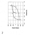
Fig. 1 is a graph illustrating a relation between stress and strain of a first cycle of tension-compression deformation in Example 2 (4S). -
Fig. 2 is a graph illustrating changes in stress amplitude by cyclic tension-compression deformation of alloys according to Examples and Comparative Examples. - Typically, a damping alloy indicates a structural material which absorbs mechanical vibrations in machine tools, precision equipment, automobiles, or the like by mainly realizing both of an increase of internal friction in an elastic deformation region and high strength as a metallic material.
- In order to distinguish from this, meanwhile, the term "seismic damping" is sometimes used to describe damping for a main countermeasure against earthquake motion, but the term "damping" is being mainly used in recent years from the reason that control of ordinary vibration due to swing by wind other than the earthquake is also important to a damper for constructions.
- According to this trend, the term "damping" is also used in the present invention, but the main subject thereof relates to vibration control on constructions during an earthquake. However, it is assumed that one of effects also includes the control of relatively small vibration due to the swing by wind or the like.
- An damping alloy according to the present invention is an damping alloy in which elasto-plastic deformation reversibly takes place due to a mutual conversion of a γ austenite phase and a ε martensite phase by adjusting the content of Mn, Cr, Ni, and Si in an Fe-Mn-(Cr, Ni)-Si-based alloy and irreversible deformation such as a formation of an α' martensite phase is suppressed, such that proof stress is 280 MPa or less, stress amplitude is 400 MPa or less after cyclic tension-compression deformation at an amplitude of 1%, and the number of cycles to fracture is 2000 cycles or more.
- In addition to slipping motion of lattice dislocations which is a plastic deformation mechanism of a general metal, a plastic deformation mechanism in an austenitic iron-based alloy takes various forms such as slipping motion of extended dislocations, in which a lattice dislocation is moved by being separated into two partial dislocations and a stacking fault sandwiched therebetween, twinning deformation, ε martensite transformation, and α' martensite transformation, and thus a plurality of plastic deformation mechanisms are usually expressed at the same time.
- In the damping alloy according to the present invention, a structural change by tension-compression plastic deformation reversibly takes place due to two-directional martensite transformation between the γ austenite phase and the ε martensite phase, thereby suppressing cyclic hardening and increasing the number of cycles to fracture.
- For this, a pre-deformation state is in a γ austenite single-phase, and the plastic deformation mechanism preferably proceeds mainly due to ε martensite transformation. At this time, twinning deformation, lattice dislocation slipping, or extension dislocation slipping, which occurs inevitably and concurrently with the ε martensite transformation, may be partially included, but α' martensite transformation should be suppressed because of significantly hardening an alloy.
- Mn is an essential additive element having a critical influence on the plastic deformation mechanism of the Fe-Mn-(Cr, Ni)-Si-based alloy. Mn has a behavior of stabilizing the γ austenite phase and lowering stacking fault energy in the iron-based alloy, thereby easily occurring martensite transformation from the γ austenite phase to the s martensite phase.
- Accordingly, during the tension-compression plastic deformation, the ε martensitic transformation and reverse transformation thereof alternately occur from a deformation-induced γ, and the formation of the α' martensite phase can be suppressed, thereby improving fatigue properties.
- Some of the austenite stabilizing function can be achieved using Ni instead of Mn, and some of the lowering function of the stacking fault energy can be achieved using Cr.
- In order to reduce melting costs, the present invention necessarily includes Cr or Ni as an alternative additive element of Mn. Further, Al having an effect of improving the damping properties of an Fe-Mn-Si-based shape memory alloy may be also added as an alternative element of Mn.
- An effect of Mn, Cr, Ni, or Al on the plastic deformation mechanism can be represented in terms of mass% of Mn having the same effect as those. In the present invention, this is defined as Mn equivalent weight ([%Mn]eq), and the Mn equivalent weight is expressed by the following Formula (1) using the content (mass%) of each component element.

- In the Formula, [%Mn], [%Cr], [%Ni], and [%Al] represent contents (mass%) of Mn, Cr, Ni, and Al as a chemical component of the damping alloy, respectively.
- Furthermore, in the present invention, the range of the Mn equivalent weight satisfies the condition expressed by the following Formula (2) to exhibit the two-way martensitic transformations between the γ austenite phase and the ε martensite phase.

- When the Mn equivalent weight is 37 mass% or less, the thermodynamic stability of the ε martensite phase becomes very higher, so that once the ε martensite phase is deformation-induced it will not be reversely transformed into the γ austenite phase even when it is deformed in a reverse direction.
- As a result, the volume ratio of the ε martensite phase monotonously increases by the cyclic tension-compression deformation, and crack initiation probability or crack propagation rate rises at a place where the ε martensite phases, which have been formed, collide with each other and thus the number of cycles to fracture declines when the volume ratio is 50% or more by volume.
- Furthermore, when the Mn equivalent weight is 30 mass% or less, since the ε martensite phase having the volume ratio of 15% or more by volume is already formed at the time of cooling from a solution heat-treatment temperature to a room temperature and a subsequent formation of a deformation-induced ε martensite phase is hindered, the number of cycles to fracture declines.
- In addition, when the Mn equivalent weight is 45 mass% or more, the stacking fault energy increases and the ε martensite is not formed.
- Meanwhile, Si as another essential additive element has little influence on the Mn equivalent weight, but it was apparent by experiments that Si improves reversibility of the two-directional martensite transformation between the γ austenite phase and the ε martensite phase and thus improves the number of cycles to fracture. Even when Si is not added, the number of cycles to fracture can be about 2000 cycles, but the number of cycles to fracture is more drastically increased by the addition of Si and the largest effect is exhibited when the additive amount of Si is near 4 mass%.
- However, when Si is excessively added, the number of cycles to fracture is decreased, and, particularly, when Si is added to be 6.5 mass% or more, the alloy is significantly hardened, resulting in causing a problem that the stress amplitude of the cyclic tension-compression deformation rises in some cases.
- In the additive amount of Mn, Cr, Ni, and Si, it is important to adjust the balance between the total amount of Ni and Mn which are austenite stabilizing elements and the total amount of Cr, Si, and Al which are ferrite stabilizing elements such that a metal structure before the deformation becomes a γ austenite single-phase. As the concentration of the ferrite stabilizing elements is high and the concentration of the austenite stabilizing elements is low, a δ ferrite phase is likely to form, and an α' martensite phase is likely to form when both of the concentration of the ferrite stabilizing elements and the concentration of the austenite stabilizing elements are low.
- From experimental results by the inventors, when the alloy system of the present invention is water quenched after being subjected to a solution heat treatment at 1000°C for one hour, it has been found that the additive amount of component elements satisfied conditions of the following Formula (3) so as to suppress the formation of the δ ferrite phase and to make the γ austenite single-phase.

- In the Formula, [%Ni], [%Mn], [%Cr], [%Si], and [%Al] represent contents (mass%) of Ni, Mn, Cr, Si, and Al as chemical components of the damping alloy, respectively.
- The additive amount of each of Mn, Cr, Ni, Si, and Al as the component elements is limited by restrictions on production in addition to each condition described above. The description will be made below in detail.
- Mn is an essential additive element having two effects of austenite stabilization and stacking-fault energy reduction; in the damping alloy of Patent Literature 6 which is added with Mn of 30 mass%, however, reduction in Mn yield due to evaporation or oxidation of Mn and reaction with refractory in a melting furnace inevitably occur and it is difficult to melt at a practically allowable cost.
- In the present invention, the additive amount of Mn is set to be 28 mass% or less by the addition of Cr or Ni to reduce the melting cost. Further, when the additive amount of Mn is less than 20 mass%, it is possible to produce an alloy using arc melting furnace which is suitable for mass production.
- Meanwhile, when the additive amount of Mn is less than 10 mass%, both of Cr which is effective in the stacking-fault energy reduction and Ni which is the austenite stabilizing element should be added in great quantities, thereby causing the reduction in melting costs but allowing an increase in material costs.
- Furthermore, when the additive amount of Mn is less than 5 mass%, the α' martensite phase harmful to the fatigue properties is inevitably formed even when the additive amount of Cr and Ni is adjusted in any way. From the above, in the present invention, the additive amount of Mn is preferably in the range of 5 mass% ≤ Mn ≤ 28 mass%, and more preferably 10 mass% ≤ Mn ≤ 20 mass%.
- Cr is an element which reduces the stacking-fault energy of the γ austenite phase and promotes the martensite transformation to the ε martensite phase, thereby improving the fatigue properties of the damping alloy according to the present invention. In addition, the element also contributes to improve corrosion resistance or high-temperature oxidation resistance. However, when the additive amount of Cr is 15 mass% or more, it is difficult to suppress the formation of the α' martensite phase even when the additive amount of other components is adjusted in any way and a low-melting point intermetallic compound is further formed by reacting with Si, so that it is difficult to melt the alloy. From the above, in the present invention, the additive amount of Cr is in the range of 0 mass% ≤ Cr ≤ 15 mass%.
- Ni is an alternative element of Mn for the austenite stabilizing behavior. In particular, when the additive amount of Mn is less than 20 mass%, the γ austenite single-phase, which is in a state before the deformation, is not obtained if Ni of 2 mass% or more is not added as an austenite stabilizing element.
- Meanwhile, when the additive amount of Ni is 15 mass% or more, a low-melting point intermetallic compound is formed by reaction with Si, thereby deteriorating hot workability of an alloy.
- In addition, from the viewpoint of material costs, the additive amount of Ni which is an expensive element is preferably less than 10 mass%. From the above, in the present invention, the additive amount of Ni is preferably in the range of 0 mass% ≤ Ni < 15 mass% and more preferably 2 mass% ≤ Ni ≤ 10 mass%.
- With respect to Cr and Ni described above, at least either of both elements is contained in the damping alloy of the present invention and both elements are not set to be 0 mass% at the same time.
- Si is an essential element of an Fe-Mn-Si-based shape memory alloy and the component range thereof is set to be 3.5 to 8 mass%, but the concentration of Si in a commercially available alloy is in the range of 5 to 6 mass% or less.
- Meanwhile, even in the damping alloy of the present invention, Si is an element having an important role in improvement of the number of cycles to fracture, but the optimal component concentration therein is different from that in the shape memory alloy. From experiment and research results by the inventors, to obtain the number of cycles to fracture of 2000 cycles or more in the present invention, the additive amount of Si is in the range of 0 mass% < Si < 6.5 mass% and more preferably 2 mass% ≤ Si ≤ 6 mass%.
- Al is an element having an influence on the Mn equivalent weight by factor 5 and thus may be added as an alternative element of Mn. However, since the element is also a ferrite stabilizing element, when Al is excessively added, the δ ferrite phase is easily formed. When a heat treatment is performed in an atmosphere, there is also a possibility that Al having high affinity with nitrogen forms nitrides to embrittle the alloy.
- In this way, the Mn equivalent weight is effectively adjusted by adding even a trace amount of Al but a negative effect also occurs when Al is excessively added. Therefore, the additive amount of Al is in the range of 0 mass% ≤ Al < 3 mass%.
- In the present invention, Co, Cu, C, or N may be added as an element having an alternative effect of Mn in addition to the above elements. However, since the addition of Co and Cu leads to an increase in material costs, the additive amounts of Co and Cu are in the following range in the present invention, respectively: Co < 0.2 mass% and Cu < 2 mass%.
- In addition, since C and N cause a solid-solution hardening behavior of an alloy to increase yield strength and thus to impair performance of the alloy as a core material for an elasto-plastic damper, the upper limits of the additive amounts of C and N are in the following range, respectively: C < 0.1 mass% and N < 0.08 mass%.
- In addition, for the purpose of removing interstitial elements C and N which are formed in an iron-based parent phase as a solid solution, carbides or nitrides are formed by the addition of an element such as Nb, Ta, V, Ti, or Mo having high affinity with C or N, which is widely carried out in the arts.
- In the damping alloy of the present invention, it is necessary to minimize the effect of the solid-solution hardening of the parent phase due to the interstitial element C or N so as to reduce the proof stress or the stress amplitude in the cyclic tension-compression deformation. Therefore, even in the present invention, Nb, Ta, V, Ti, or Mo may be added by applying the conventional method so as to remove C or N formed as a solid solution.
- However, when the additive amount of each element is too large, the proof stress or the stress amplitude increases on the contrary due to precipitation hardening of carbides or nitrides which are formed. In order to avoid this, each of the elements is in the following range in the present invention: Nb < 0.05 mass%, Ta < 0.05 mass%, V < 0.05 mass%, Ti < 0.05 mass%, and Mo < 0.05 mass%.
- In the state before the deformation, the γ austenite single-phase is preferably formed, but the ε martensite phase may be formed in small quantity. In an alloy which is adjusted in a state where the ε martensite transformation is easily induced by the deformation, the ε martensite phase may be unintentionally formed in some cases due to an environmental temperature change, a machining influence or the like.
- Since the unintentionally formed ε martensite phase differs from a subsequent deformation-induced ε martensite phase in a normal crystallographic orientation and becomes a barrier to the growth of the deformation-induced ε martensite phase, the volume ratio thereof is set to be less than 15 vol%.
- The tension-compression plastic deformation of the damping alloy according to the present invention is mainly carried out in such a manner that the martensite transformation to the ε martensite phase from the γ austenite phase and the reverse transformation thereof alternately occur. The ε martensite phase induced at the time of the tensile deformation is reversely transformed to the γ austenite phase when a deformation direction is reversed to a compressive direction.
- Meanwhile, the compressive deformation causes not only a reverse transformation of the tension-induced ε martensite phase but also a new ε martensite phase having a crystal orientation, which is different from a crystal orientation during the tension deformation. The compression-induced ε martensite phase is also reversely transformed to the γ austenite phase when the deformation is again reversed to the tension. In this way, since the increase in cumulative volume ratio of the ε martensite phase caused by the cyclic tension-compression deformation becomes smaller by cyclic formation and extinction of the tension-induced ε martensite phase and the compression-induced ε martensite phase in an alternate manner by the cyclic tension and compression, the damping alloy of the present invention has excellent fatigue properties.
- However, the volume ratio of the ε martensite phase gradually increases as the strain amplitude or the number of cycles increases; and when the volume ratio thereof is 50% or more by volume, the crack initiation probability or the crack propagation rate increases, thereby causing the fracture in some cases. Accordingly, in order for that the number of cycles to fracture is 2000 cycles or more with respect to the tension-compression deformation at the amplitude of 1 %, the volume ratio of the ε martensite is preferably less than 50 vol% after the deformation is carried out by the 2000 cycles.
- In addition, since the α' martensite phase leads to hardening of the alloy, the volume ratio thereof should be less than 3 vol%. When the volume ratio of the α' martensite phase is 3% or more by volume, the stress amplitude increases due to the hardening; the increase in stress amplitude induces a new α' martensite phase transformation in a chain reaction, resulting in a decrease in the number of cycles to fracture as well as a decrease in damper performance due to an increase in stress level.
- The proof stress of the damping alloy according to the present invention is set to be 280 MPa or less. When the proof stress is higher than this value, the cross-sectional area of the core material for the damper to be used to optimize the operation start strength of the damper becomes too small, the buckling easily occurs at the time of the elasto-plastic deformation. In order to avoid the buckling, a buckling stiffener should be provided, but the installation of the buckling stiffener leads to an increase in production costs of a damper member.
- In addition, when the cyclic tension-compression deformation is carried out, the stress amplitude increases due to cyclic hardening, but from the viewpoint of long-term use, the stress amplitude is preferably set to be 400 MPa or less after the cyclic tension-compression deformation at the amplitude of 1 % is carried out 100 times or more.
- When the stress amplitude exceeds 400 MPa, the yield strength of the core material for the damper rises to become higher than the strength of the building body after the big earthquake occurs, and thus it is difficult to operate as a damper in the subsequent earthquake. Since the damping alloy of the present invention is the core material for the seismic damper capable of corresponding even to the long-period ground motion and is intended to be used for the seismic damping device of a skyscraper, the final number of cycles leading to the fracture or buckling is 2000 cycles or more.
- The present invention will be described below in detail based on Examples. Naturally, the present invention is not limited by these Examples.
- Each of alloys consisting of compound chemical compositions according to Examples 1 to 6 and Comparative Examples 1 to 8 indicated in Table 1 was prepared with 10 kg using a vacuum induction melting furnace, and after being subjected to hot forging and hot rolling at 1100°C, the prepared alloy was heated for one hour at 1000°C under an argon atmosphere and then was cooled with water thereby making an ingot. The additive amount of each component indicated in Table 1 is represented in terms of mass%.
- In order to facilitate the understanding of features of compound components of Examples and Comparative Examples in Table 1, Examples 1 to 6 are also referred to as
symbols 2S, 4S, 6S, 2A, 25M8N, and 25M15C, respectively and Comparative Examples 1 to 8 are also referred to assymbols [Table 1] Symbol Fe Mn Cr Ni Al Si Others Mn equivalent weight Example 1 2S Bal. 15 10 8 0 2 41 Example 2 4S Bal. 15 10 8 0 4 41 Example 3 6S Bal. 15 10 8 0 6 41 Example 4 2A Bal. 15 10 3 2 4 41 Example 5 25M8N Bal. 25 0 3 0 4 41 Example 6 25M15C Bal. 25 15 0 0 4 40 Comparative Example 1 0S Bal. 15 10 8 0 0 41 Comparative Example 2 8S Bal. 15 10 8 0 8 41 Comparative Example 3 5M Bal. 5 10 8 0 6 31 Comparative Example 4 25M Bal. 25 10 8 0 6 51 Comparative Example 5 2N Bal. 15 10 2 0 6 29 Comparative Example 6 15N Bal. 15 10 15 0 6 55 Comparative Example 7 PRE Bal. 28 5 0 0 6 0.5vol%-NbC 33 Comparative Example 8 30M1A Bal. 30 0 0 1 5 35 - From each ingot of Examples 1 to 6 and Comparative Examples 1 to 8, a low-cycle fatigue test piece having a 8 mm-diameter parallel portion was prepared by lathe working and was subjected to a strain control low-cycle fatigue test at an amplitude of 1 % with a triangle wave of 0.1 Hz under an atmosphere of room temperature.
-
Fig. 1 illustrates a relation between stress and strain of a first cycle of tension-compression deformation in Example 2 (4S). From a state O with no deformation A, increase in tensile strain causes an elastic deformation OA, which is followed by a plastic deformation reaching to a point B, where tensile strain is 1%. - Thereafter, when the deformation is reversed to the compression, the curve reaches to a point D, where strain is zero, after an elastic deformation part BC in which tensile elastic stress decreases in proportion to a decrease in tensile strain as tensile plastic distortion gradually decreases.
- When compression deformation further proceeds, compressive plastic strain occurs. When the compression strain reaches to a point E of -1 %, the compression deformation is again changed into tensile strain, and an elastic deformation part EF is followed by a plastic deformation part FG to complete the first cycle. The second cycle starts along a curve GB' indicated by a dotted line, and then cyclic deformation is carried out in the same manner as the first cycle.
- Work energy equal to an area drawn by the stress-strain curve formed in one-cycle deformation is converted into thermal energy, and is absorbed to mitigate the vibration.
- During the tensile deformation, a start point of the plastic deformation was evaluated by 0.2% proof stress. In addition, a stress amplitude in the tension-compression deformation was obtained from tension-side maximum stress as illustrated in
Fig. 1 . The same evaluation was performed on all of the alloys according to Examples 1 to 6 and Comparative Examples 1 to 8. In addition,Fig. 2 illustrates changes in the stress amplitude by the cyclic tension-compression deformation of alloys according to Example 1 (2S), Example 2 (4S), Example 3 (6S), Comparative Example 1 (0S), Comparative Example 3 (5M), Comparative Example 4 (25M), Comparative Example 5 (2N), Comparative Example 7 (PRE), and Comparative Example 8 (30M1A). - Many alloys indicated a generally stable stress amplitude after being repeatedly hardened at initial 10 cycles. However, the alloy 5M was repeatedly hardened even after 10 cycles. In addition, the alloy PRE was initially hardened small and indicated a stable stress amplitude after being remarkably hardened from 10 cycles to 200 cycles. In order to evaluate the changes in the stress amplitude due to the cyclic tension-compression deformation, a stress amplitude (σa) at 100-th cycle was obtained and a hardening rate was calculated using the following Equation (4).

[Table 2] Symbol Proof stress σ 0.2 (MPa) Stress amplitude at first cycle σ a1 (MPa) Stress amplitude at 100-th cycleσ a100 (MPa) Hardening rate Number of fracture cycles Nf (cycles) Note Example 1 2S 201 230 364 0.58 3,222 Example 2 4S 222 285 362 0.27 7,319 Example 3 6S 260 333 400 0.20 4,506 Example 2A 241 302 385 0.27 2,117 Example 5 25M8N 208 252 335 0.33 2,597 Example 6 25M15C 218 274 380 0.39 3,200 Comparative Example 1 0S 160 201 337 0.68 1,992 Comparative Example 2 8S - - - - - Rolling crack Comparative Example 3 5M 256 298 572 0.92 282 Comparative Example 4 25M 300 334 401 0.20 887 Comparative Example 5 2N 248 401 671 0.67 474 Comparative Example 6 15N - - - - - Rolling crack Comparative Example 7 PRE 290 495 620 0.25 3,002 Comparative Example 8 30M1A 237 308 437 0.42 2,067 - In all
alloys 2S, 4S, 6S, 2A, 25M8N, and 25M15C according to Examples 1 to 6, the proof stress is 280 MPa or less, the stress amplitude at 100-th cycle is 400 MPa or less, and the final number of cycles is 2000 cycles or more. In the alloy 0S according to Comparative Example 1 not added with Si, the number of cycles to fracture was slightly below 2000. - In the alloy 8S according to Comparative Example 2 added with Si in larger amount than the component range of the present invention, it was not possible to prepare test pieces due to occurrence of rolling cracks. It was considered that the crack occurrence resulted from the formation of low-melting point intermetallic compounds.
- In the alloy 5M according to Comparative Example 3 having the Mn equivalent weight less than 31, the cyclic hardening was significant and the number of cycles to fracture was also 1000 or less. It was considered that the cyclic hardening resulted from the deformation-induced α' martensite phase.
- In the
alloy 25M according to Comparative Example 4 having the increased Mn equivalent weight of 51, since the ε-phase is not formed by the deformation, the number of cycles to fracture was 1000 or less. - In the
alloy 2N according to Comparative Example 5 in which the additive amount of Ni was 2 mass% lower than the inventive material and consequently, the Mn equivalent weight was reduced to 29, the cyclic hardening was significantly high and the number of cycles to fracture was also 1000 or less. It was considered that this resulted in the formation of the ε martensite phase of 50% or more by volume and the α' martensite phase. - In the alloy 15N according to Comparative Example 6 containing Ni of 15 mass% with more concentration than the alloys of Examples, cracks occurred during hot rolling, and thus test pieces could not be prepared. It was considered that this was because Ni formed a low-melting point intermetallic compound by reacting with Si.
- The alloy PRE according to Comparative Example 7 is a damping alloy added with NbC precipitates which is disclosed in Patent Literature 5. The number of cycles to fracture is 3000 cycles or more which is excellent, but the stress amplitude is 620 MPa which is very high.
- The alloy 30M1A according to Comparative Example 8 is an Al-added damping alloy disclosed in Patent Literature 6. The number of cycles to fracture is 2000 or more and the stress amplitude is also low, but since the content of Mn of 30 mass% is included, it is not suitable for mass production.
- From these results, it was confirmed that the damping alloy according to Examples 1 to 6 satisfying conditions defined in the present invention is a damping alloy in which proof stress and stress amplitude after cyclic tension-compression deformation are lowered and the number of cycles to fracture is increased compared to the alloys according to Comparative Examples 1 to 8 deviated from the conditions of the present invention, the damping alloy being capable of being used in a maintenance-free manner even after long-period ground motion and being mass-produced.
- By using the damping alloy according to the present invention, it is possible to manufacture a low-cost seismic damping device, which is capable of being operated at low stress and being used in maintenance-free manner even when being exposed to earthquakes repeatedly, as an elasto-plastic damper for restraining vibrations of architectural constructions caused by an earthquake, swing by wind, or the like.
- As a high-performance damper without impairing the damping performance even when a large amplitude swing such as a long-period ground motion occurs for a long period of time, it is possible to be especially used in the damping of a skyscraper. In addition, it is expected that the effect of restraining the vibration of places deformed repeatedly by the large strain is exhibited in all forms of the architectural constructions such as chemical plants, power plants, halls, towers, fuel tanks, elevated railroads or roads, bridges, pipelines, tunnels, or wind power generation facilities.
Claims (5)
- A damping alloy that is an Fe-Mn-(Cr, Ni)-Si-based damping alloy containing at least one of Cr or Ni or further contains Al, the damping alloy containing component compositions of:5 mass% ≤ Mn ≤ 28 mass%;0 mass% ≤ Cr ≤ 15 mass%;0 mass% ≤ Ni < 15 mass%;0 mass% < Si < 6.5 mass%; and0 mass% ≤ Al < 3 mass%,the balance being Fe and inevitable impurities, whereinthe component compositions satisfy the following conditions:[%Ni] + 0.5 [%Mn] > 0.75 [%Cr] + 1.125 [%Si] + 2 [%Al]; and37 < [%Mn] + [%Cr] + 2 [%Ni] + 5 [%Al] < 45 (wherein [%Ni], [%Mn], [%Cr], [%Si], and [%Al] represent contents (mass%) of Ni, Mn, Cr, Si, and Al, respectively).
- The damping alloy according to claim 1, wherein the damping alloy contains component compositions of:10 mass% ≤ Mn ≤ 20 mass%; and2 mass% ≤ Ni ≤ 10 mass%.
- The damping alloy according to claim 1 or 2, wherein the damping alloy contains a component composition of 2 mass% ≤ Si ≤ 6 mass%.
- The damping alloy according to any one of claims 1 to 3, wherein
a metallographic structure of the alloy subjected to plastic working and solution treatment includes only a ε martensite phase (HCP structure) less than 15 vol% and a γ austenite phase (FCC structure) as a remaining part; and
after cyclic tension-compression deformation at an amplitude of 1% is further carried out 100 cycles or more from the metallographic structure, the alloy has a metallographic structure of the ε martensite phase less than 50 vol%, an α' martensite phase less than 3 vol%, and the γ austenite phase as a remaining part. - The damping alloy according to any one of claims 1 to 4, wherein
proof stress is 280 MPa or less,
stress amplitude is 400 MPa or less after the cyclic tension-compression deformation at the amplitude of 1% is carried out 100 cycles or more, and
the number of cycles to fracture is 2000 cycles or more.
Applications Claiming Priority (2)
| Application Number | Priority Date | Filing Date | Title |
|---|---|---|---|
| JP2012287955A JP6182725B2 (en) | 2012-12-28 | 2012-12-28 | Damping alloy |
| PCT/JP2013/084119 WO2014103884A1 (en) | 2012-12-28 | 2013-12-19 | Damping alloy |
Publications (3)
| Publication Number | Publication Date |
|---|---|
| EP2940175A1 true EP2940175A1 (en) | 2015-11-04 |
| EP2940175A4 EP2940175A4 (en) | 2016-08-24 |
| EP2940175B1 EP2940175B1 (en) | 2021-02-03 |
Family
ID=51020971
Family Applications (1)
| Application Number | Title | Priority Date | Filing Date |
|---|---|---|---|
| EP13869412.0A Active EP2940175B1 (en) | 2012-12-28 | 2013-12-19 | Damping alloy |
Country Status (4)
| Country | Link |
|---|---|
| EP (1) | EP2940175B1 (en) |
| JP (1) | JP6182725B2 (en) |
| KR (1) | KR102144708B1 (en) |
| WO (1) | WO2014103884A1 (en) |
Cited By (1)
| Publication number | Priority date | Publication date | Assignee | Title |
|---|---|---|---|---|
| CN112029988A (en) * | 2020-09-03 | 2020-12-04 | 成都科宁达材料有限公司 | Method for improving damping performance of Fe-Cr-Mo-based damping alloy |
Families Citing this family (8)
| Publication number | Priority date | Publication date | Assignee | Title |
|---|---|---|---|---|
| JP6696754B2 (en) * | 2015-11-05 | 2020-05-20 | 株式会社ビー・ビー・エム | Composite vibration damper for structures |
| JP2017193825A (en) * | 2016-04-18 | 2017-10-26 | 株式会社ビービーエム | Buckling-restrained vibration control device |
| JP6887642B2 (en) | 2017-04-04 | 2021-06-16 | 国立研究開発法人物質・材料研究機構 | Fe-Mn-Si alloy casting material with excellent low cycle fatigue characteristics |
| JP7555733B2 (en) | 2020-06-05 | 2024-09-25 | 株式会社竹中工務店 | Welded assembly steel |
| KR102835321B1 (en) | 2020-06-24 | 2025-07-17 | 가부시키가이샤 다케나카 고무텐 | Welded structures and Fe-Mn-Cr-Ni-Si alloys used therein |
| KR20230073482A (en) * | 2021-11-19 | 2023-05-26 | 한국재료연구원 | Excellent stength and excellent toughness medium entropy alloy and method for manufacturing the same |
| CN116292704B (en) * | 2023-03-30 | 2025-10-28 | 上海材料研究所有限公司 | A fatigue-resistant arc-shaped shock-absorbing element capable of providing high damping force and its application |
| CN117210756B (en) * | 2023-10-12 | 2025-10-03 | 鞍钢集团北京研究院有限公司 | Ultra-low yield ratio and low yield point damping mild steel and preparation method thereof |
Family Cites Families (19)
| Publication number | Priority date | Publication date | Assignee | Title |
|---|---|---|---|---|
| JPS62112751A (en) * | 1985-11-09 | 1987-05-23 | Nippon Steel Corp | Manufacturer of ferrous shape memory alloy sheet metal or wire |
| JPS6455361A (en) * | 1987-08-25 | 1989-03-02 | Takeshi Masumoto | Fe-base shape memory alloy |
| JPH0526274A (en) | 1991-07-18 | 1993-02-02 | Kajima Corp | Elastic-plastic damper |
| JPH05106367A (en) | 1991-10-15 | 1993-04-27 | Kajima Corp | Lead damper |
| US5219051A (en) | 1991-10-25 | 1993-06-15 | Honeywell Inc. | Folded viscous damper |
| JPH05186852A (en) * | 1992-01-11 | 1993-07-27 | Sumitomo Metal Ind Ltd | Damping steel, damping weld steel tube and their manufacture |
| AU6361396A (en) * | 1995-07-11 | 1997-02-10 | Kari Martti Ullakko | Iron-based shape memory and vibration damping alloys containing nitrogen |
| JPH1036943A (en) * | 1996-07-24 | 1998-02-10 | Taiheiyo Kinzoku Kk | Method for producing Fe-Mn-Si based shape memory alloy |
| JP2001146855A (en) | 1999-11-19 | 2001-05-29 | Shimizu Corp | Viscoelastic damper |
| JP2003105438A (en) * | 2001-09-27 | 2003-04-09 | National Institute For Materials Science | Thermomechanical processing method for NbC-added Fe-Mn-Si based shape memory alloy |
| CN1158399C (en) * | 2002-09-03 | 2004-07-21 | 四川大学 | Deformation-induced aging iron-based shape memory alloy and preparation method thereof |
| JP4709555B2 (en) | 2005-01-11 | 2011-06-22 | 独立行政法人物質・材料研究機構 | Damping material using iron-based shape memory alloy, damping device using this material, and method of using iron alloy-based damping material |
| JP5035825B2 (en) | 2006-08-31 | 2012-09-26 | 独立行政法人物質・材料研究機構 | Damping alloy |
| JP2009155719A (en) * | 2007-12-25 | 2009-07-16 | Tk Techno Consulting:Kk | Vibration-damping steel pipe and manufacturing method therefor |
| JP2010043304A (en) * | 2008-08-11 | 2010-02-25 | Daido Steel Co Ltd | Fe-BASED DAMPING ALLOY |
| JP2010156041A (en) | 2008-12-04 | 2010-07-15 | Daido Steel Co Ltd | Two-way shape-recovery alloy |
| JP2011214127A (en) | 2010-03-31 | 2011-10-27 | Tk Techno Consulting:Kk | Vibration-suppression/base-isolation damper device |
| JP2012102391A (en) | 2010-11-08 | 2012-05-31 | Tk Techno Consulting:Kk | Building exterior material |
| CN102435624B (en) * | 2011-11-23 | 2013-10-30 | 天津大学 | Method for representing recovery characteristics of Fe-Mn-Si-based memory alloy by in-situ X-ray diffraction |
-
2012
- 2012-12-28 JP JP2012287955A patent/JP6182725B2/en active Active
-
2013
- 2013-12-19 EP EP13869412.0A patent/EP2940175B1/en active Active
- 2013-12-19 WO PCT/JP2013/084119 patent/WO2014103884A1/en not_active Ceased
- 2013-12-19 KR KR1020157015190A patent/KR102144708B1/en active Active
Cited By (2)
| Publication number | Priority date | Publication date | Assignee | Title |
|---|---|---|---|---|
| CN112029988A (en) * | 2020-09-03 | 2020-12-04 | 成都科宁达材料有限公司 | Method for improving damping performance of Fe-Cr-Mo-based damping alloy |
| CN112029988B (en) * | 2020-09-03 | 2022-02-18 | 成都科宁达材料有限公司 | Method for improving damping performance of Fe-Cr-Mo-based damping alloy |
Also Published As
| Publication number | Publication date |
|---|---|
| KR20150117637A (en) | 2015-10-20 |
| EP2940175B1 (en) | 2021-02-03 |
| KR102144708B1 (en) | 2020-08-14 |
| JP6182725B2 (en) | 2017-08-23 |
| JP2014129567A (en) | 2014-07-10 |
| WO2014103884A1 (en) | 2014-07-03 |
| EP2940175A4 (en) | 2016-08-24 |
Similar Documents
| Publication | Publication Date | Title |
|---|---|---|
| EP2940175B1 (en) | Damping alloy | |
| JP4498847B2 (en) | Austenitic high Mn stainless steel with excellent workability | |
| EP3235923B1 (en) | High-strength steel plate with yield strength of 800 mpa and more and production method therefor | |
| JP5385760B2 (en) | Cold-formed square steel pipe with excellent earthquake resistance | |
| EP2557189B1 (en) | Ferrite stainless steel sheet having high thermal resistance and processability, and method for manufacturing the same | |
| JPH0277523A (en) | Production of building low yield ratio steel having excellent fire resistance and building steel material using same steel | |
| CN113046635A (en) | High-strength and high-toughness corrosion-resistant steel for ocean engineering and manufacturing method thereof | |
| KR102835321B1 (en) | Welded structures and Fe-Mn-Cr-Ni-Si alloys used therein | |
| JP4327030B2 (en) | Low Ni austenitic stainless steel with excellent overhanging and rust resistance | |
| JP2011219809A (en) | High strength steel sheet | |
| KR20140119216A (en) | High manganese alloy and the manufacturing method for high manganese alloy | |
| JP2011214127A (en) | Vibration-suppression/base-isolation damper device | |
| CN103826766B (en) | Manufacturing method of austenitic stainless steel | |
| JP7297096B2 (en) | Shaped steel and its manufacturing method | |
| JP5091733B2 (en) | Stainless steel for low Ni body parts with excellent workability and shock absorption performance | |
| JPH0830253B2 (en) | Precipitation hardening type martensitic stainless steel with excellent workability | |
| JP4066908B2 (en) | Tempered steel material for damping damper and method for manufacturing the same | |
| JP2011047008A (en) | Austenitic stainless steel for spring | |
| JPH0339418A (en) | Production of steel stock for steel-frame structure minimal in reduction in elastic modulus at high temperature | |
| JPH0742550B2 (en) | Stainless steel with excellent strength and ductility | |
| JP3540927B2 (en) | Low yield point steel with excellent toughness | |
| EP3795711B1 (en) | Low cr ferritic stainless steel having excellent damping capacity and manufacturing method therefor | |
| JP2008156752A (en) | Method for manufacturing shock absorbing member | |
| JPS58107476A (en) | High tensile steel excellent sulfide stress corrosion cracking resistance | |
| JPH1096024A (en) | Manufacturing method of earthquake-resistant building steel with excellent fire resistance |
Legal Events
| Date | Code | Title | Description |
|---|---|---|---|
| PUAI | Public reference made under article 153(3) epc to a published international application that has entered the european phase |
Free format text: ORIGINAL CODE: 0009012 |
|
| 17P | Request for examination filed |
Effective date: 20150728 |
|
| AK | Designated contracting states |
Kind code of ref document: A1 Designated state(s): AL AT BE BG CH CY CZ DE DK EE ES FI FR GB GR HR HU IE IS IT LI LT LU LV MC MK MT NL NO PL PT RO RS SE SI SK SM TR |
|
| AX | Request for extension of the european patent |
Extension state: BA ME |
|
| DAX | Request for extension of the european patent (deleted) | ||
| A4 | Supplementary search report drawn up and despatched |
Effective date: 20160727 |
|
| RIC1 | Information provided on ipc code assigned before grant |
Ipc: C22C 38/58 20060101ALI20160721BHEP Ipc: C22C 38/06 20060101ALI20160721BHEP Ipc: C22C 38/00 20060101AFI20160721BHEP Ipc: C21D 6/00 20060101ALI20160721BHEP Ipc: C21D 8/00 20060101ALI20160721BHEP Ipc: C22C 38/34 20060101ALI20160721BHEP |
|
| RIC1 | Information provided on ipc code assigned before grant |
Ipc: C22C 38/34 20060101ALI20160829BHEP Ipc: C22C 38/58 20060101ALI20160829BHEP Ipc: C21D 6/00 20060101ALI20160829BHEP Ipc: C22C 38/00 20060101AFI20160829BHEP Ipc: C21D 8/00 20060101ALI20160829BHEP Ipc: C22C 38/06 20060101ALI20160829BHEP |
|
| STAA | Information on the status of an ep patent application or granted ep patent |
Free format text: STATUS: EXAMINATION IS IN PROGRESS |
|
| 17Q | First examination report despatched |
Effective date: 20180813 |
|
| GRAP | Despatch of communication of intention to grant a patent |
Free format text: ORIGINAL CODE: EPIDOSNIGR1 |
|
| STAA | Information on the status of an ep patent application or granted ep patent |
Free format text: STATUS: GRANT OF PATENT IS INTENDED |
|
| INTG | Intention to grant announced |
Effective date: 20200506 |
|
| GRAJ | Information related to disapproval of communication of intention to grant by the applicant or resumption of examination proceedings by the epo deleted |
Free format text: ORIGINAL CODE: EPIDOSDIGR1 |
|
| STAA | Information on the status of an ep patent application or granted ep patent |
Free format text: STATUS: EXAMINATION IS IN PROGRESS |
|
| INTC | Intention to grant announced (deleted) | ||
| RAP1 | Party data changed (applicant data changed or rights of an application transferred) |
Owner name: NATIONAL INSTITUTE FOR MATERIALS SCIENCE Owner name: AWAJI MATERIA CO., LTD. Owner name: TAKENAKA CORPORATION |
|
| RIN1 | Information on inventor provided before grant (corrected) |
Inventor name: NAKAMURA TERUMI Inventor name: OGAWA KAZUYUKI Inventor name: SAWAGUCHI TAKAHIRO Inventor name: KOBAYASHI SATORU Inventor name: INOUE YASUHIKO Inventor name: CHIBA YUYA Inventor name: SEKIDO NOBUAKI Inventor name: TSUZAKI KANEAKI Inventor name: NAGASHIMA NOBUO Inventor name: SUGIMURA SEIICHI Inventor name: MARUYAMA TADAKATSU Inventor name: NISHIMURA TOSHIYASU Inventor name: KUSHIBE ATSUMICHI Inventor name: FURUYA YOSHIYUKI Inventor name: SAKURAYA KAZUYUKI Inventor name: SUGATA MASAHIRO |
|
| GRAP | Despatch of communication of intention to grant a patent |
Free format text: ORIGINAL CODE: EPIDOSNIGR1 |
|
| STAA | Information on the status of an ep patent application or granted ep patent |
Free format text: STATUS: GRANT OF PATENT IS INTENDED |
|
| INTG | Intention to grant announced |
Effective date: 20200731 |
|
| GRAS | Grant fee paid |
Free format text: ORIGINAL CODE: EPIDOSNIGR3 |
|
| GRAA | (expected) grant |
Free format text: ORIGINAL CODE: 0009210 |
|
| STAA | Information on the status of an ep patent application or granted ep patent |
Free format text: STATUS: THE PATENT HAS BEEN GRANTED |
|
| AK | Designated contracting states |
Kind code of ref document: B1 Designated state(s): AL AT BE BG CH CY CZ DE DK EE ES FI FR GB GR HR HU IE IS IT LI LT LU LV MC MK MT NL NO PL PT RO RS SE SI SK SM TR |
|
| REG | Reference to a national code |
Ref country code: GB Ref legal event code: FG4D |
|
| REG | Reference to a national code |
Ref country code: AT Ref legal event code: REF Ref document number: 1359714 Country of ref document: AT Kind code of ref document: T Effective date: 20210215 Ref country code: CH Ref legal event code: NV Representative=s name: VALIPAT S.A. C/O BOVARD SA NEUCHATEL, CH Ref country code: CH Ref legal event code: EP |
|
| REG | Reference to a national code |
Ref country code: DE Ref legal event code: R096 Ref document number: 602013075592 Country of ref document: DE |
|
| REG | Reference to a national code |
Ref country code: IE Ref legal event code: FG4D |
|
| REG | Reference to a national code |
Ref country code: NL Ref legal event code: MP Effective date: 20210203 |
|
| REG | Reference to a national code |
Ref country code: LT Ref legal event code: MG9D |
|
| REG | Reference to a national code |
Ref country code: AT Ref legal event code: MK05 Ref document number: 1359714 Country of ref document: AT Kind code of ref document: T Effective date: 20210203 |
|
| PG25 | Lapsed in a contracting state [announced via postgrant information from national office to epo] |
Ref country code: FI Free format text: LAPSE BECAUSE OF FAILURE TO SUBMIT A TRANSLATION OF THE DESCRIPTION OR TO PAY THE FEE WITHIN THE PRESCRIBED TIME-LIMIT Effective date: 20210203 Ref country code: GR Free format text: LAPSE BECAUSE OF FAILURE TO SUBMIT A TRANSLATION OF THE DESCRIPTION OR TO PAY THE FEE WITHIN THE PRESCRIBED TIME-LIMIT Effective date: 20210504 Ref country code: HR Free format text: LAPSE BECAUSE OF FAILURE TO SUBMIT A TRANSLATION OF THE DESCRIPTION OR TO PAY THE FEE WITHIN THE PRESCRIBED TIME-LIMIT Effective date: 20210203 Ref country code: PT Free format text: LAPSE BECAUSE OF FAILURE TO SUBMIT A TRANSLATION OF THE DESCRIPTION OR TO PAY THE FEE WITHIN THE PRESCRIBED TIME-LIMIT Effective date: 20210604 Ref country code: LT Free format text: LAPSE BECAUSE OF FAILURE TO SUBMIT A TRANSLATION OF THE DESCRIPTION OR TO PAY THE FEE WITHIN THE PRESCRIBED TIME-LIMIT Effective date: 20210203 Ref country code: BG Free format text: LAPSE BECAUSE OF FAILURE TO SUBMIT A TRANSLATION OF THE DESCRIPTION OR TO PAY THE FEE WITHIN THE PRESCRIBED TIME-LIMIT Effective date: 20210503 Ref country code: NO Free format text: LAPSE BECAUSE OF FAILURE TO SUBMIT A TRANSLATION OF THE DESCRIPTION OR TO PAY THE FEE WITHIN THE PRESCRIBED TIME-LIMIT Effective date: 20210503 |
|
| PG25 | Lapsed in a contracting state [announced via postgrant information from national office to epo] |
Ref country code: SE Free format text: LAPSE BECAUSE OF FAILURE TO SUBMIT A TRANSLATION OF THE DESCRIPTION OR TO PAY THE FEE WITHIN THE PRESCRIBED TIME-LIMIT Effective date: 20210203 Ref country code: AT Free format text: LAPSE BECAUSE OF FAILURE TO SUBMIT A TRANSLATION OF THE DESCRIPTION OR TO PAY THE FEE WITHIN THE PRESCRIBED TIME-LIMIT Effective date: 20210203 Ref country code: RS Free format text: LAPSE BECAUSE OF FAILURE TO SUBMIT A TRANSLATION OF THE DESCRIPTION OR TO PAY THE FEE WITHIN THE PRESCRIBED TIME-LIMIT Effective date: 20210203 Ref country code: LV Free format text: LAPSE BECAUSE OF FAILURE TO SUBMIT A TRANSLATION OF THE DESCRIPTION OR TO PAY THE FEE WITHIN THE PRESCRIBED TIME-LIMIT Effective date: 20210203 Ref country code: PL Free format text: LAPSE BECAUSE OF FAILURE TO SUBMIT A TRANSLATION OF THE DESCRIPTION OR TO PAY THE FEE WITHIN THE PRESCRIBED TIME-LIMIT Effective date: 20210203 Ref country code: NL Free format text: LAPSE BECAUSE OF FAILURE TO SUBMIT A TRANSLATION OF THE DESCRIPTION OR TO PAY THE FEE WITHIN THE PRESCRIBED TIME-LIMIT Effective date: 20210203 |
|
| PG25 | Lapsed in a contracting state [announced via postgrant information from national office to epo] |
Ref country code: IS Free format text: LAPSE BECAUSE OF FAILURE TO SUBMIT A TRANSLATION OF THE DESCRIPTION OR TO PAY THE FEE WITHIN THE PRESCRIBED TIME-LIMIT Effective date: 20210603 |
|
| PG25 | Lapsed in a contracting state [announced via postgrant information from national office to epo] |
Ref country code: SM Free format text: LAPSE BECAUSE OF FAILURE TO SUBMIT A TRANSLATION OF THE DESCRIPTION OR TO PAY THE FEE WITHIN THE PRESCRIBED TIME-LIMIT Effective date: 20210203 Ref country code: EE Free format text: LAPSE BECAUSE OF FAILURE TO SUBMIT A TRANSLATION OF THE DESCRIPTION OR TO PAY THE FEE WITHIN THE PRESCRIBED TIME-LIMIT Effective date: 20210203 Ref country code: CZ Free format text: LAPSE BECAUSE OF FAILURE TO SUBMIT A TRANSLATION OF THE DESCRIPTION OR TO PAY THE FEE WITHIN THE PRESCRIBED TIME-LIMIT Effective date: 20210203 |
|
| REG | Reference to a national code |
Ref country code: DE Ref legal event code: R097 Ref document number: 602013075592 Country of ref document: DE |
|
| PG25 | Lapsed in a contracting state [announced via postgrant information from national office to epo] |
Ref country code: DK Free format text: LAPSE BECAUSE OF FAILURE TO SUBMIT A TRANSLATION OF THE DESCRIPTION OR TO PAY THE FEE WITHIN THE PRESCRIBED TIME-LIMIT Effective date: 20210203 Ref country code: ES Free format text: LAPSE BECAUSE OF FAILURE TO SUBMIT A TRANSLATION OF THE DESCRIPTION OR TO PAY THE FEE WITHIN THE PRESCRIBED TIME-LIMIT Effective date: 20210203 Ref country code: SK Free format text: LAPSE BECAUSE OF FAILURE TO SUBMIT A TRANSLATION OF THE DESCRIPTION OR TO PAY THE FEE WITHIN THE PRESCRIBED TIME-LIMIT Effective date: 20210203 Ref country code: RO Free format text: LAPSE BECAUSE OF FAILURE TO SUBMIT A TRANSLATION OF THE DESCRIPTION OR TO PAY THE FEE WITHIN THE PRESCRIBED TIME-LIMIT Effective date: 20210203 |
|
| PLBE | No opposition filed within time limit |
Free format text: ORIGINAL CODE: 0009261 |
|
| STAA | Information on the status of an ep patent application or granted ep patent |
Free format text: STATUS: NO OPPOSITION FILED WITHIN TIME LIMIT |
|
| 26N | No opposition filed |
Effective date: 20211104 |
|
| PG25 | Lapsed in a contracting state [announced via postgrant information from national office to epo] |
Ref country code: AL Free format text: LAPSE BECAUSE OF FAILURE TO SUBMIT A TRANSLATION OF THE DESCRIPTION OR TO PAY THE FEE WITHIN THE PRESCRIBED TIME-LIMIT Effective date: 20210203 |
|
| PG25 | Lapsed in a contracting state [announced via postgrant information from national office to epo] |
Ref country code: SI Free format text: LAPSE BECAUSE OF FAILURE TO SUBMIT A TRANSLATION OF THE DESCRIPTION OR TO PAY THE FEE WITHIN THE PRESCRIBED TIME-LIMIT Effective date: 20210203 |
|
| PG25 | Lapsed in a contracting state [announced via postgrant information from national office to epo] |
Ref country code: IT Free format text: LAPSE BECAUSE OF FAILURE TO SUBMIT A TRANSLATION OF THE DESCRIPTION OR TO PAY THE FEE WITHIN THE PRESCRIBED TIME-LIMIT Effective date: 20210203 |
|
| PG25 | Lapsed in a contracting state [announced via postgrant information from national office to epo] |
Ref country code: IS Free format text: LAPSE BECAUSE OF FAILURE TO SUBMIT A TRANSLATION OF THE DESCRIPTION OR TO PAY THE FEE WITHIN THE PRESCRIBED TIME-LIMIT Effective date: 20210603 |
|
| PG25 | Lapsed in a contracting state [announced via postgrant information from national office to epo] |
Ref country code: MC Free format text: LAPSE BECAUSE OF FAILURE TO SUBMIT A TRANSLATION OF THE DESCRIPTION OR TO PAY THE FEE WITHIN THE PRESCRIBED TIME-LIMIT Effective date: 20210203 |
|
| GBPC | Gb: european patent ceased through non-payment of renewal fee |
Effective date: 20211219 |
|
| REG | Reference to a national code |
Ref country code: BE Ref legal event code: MM Effective date: 20211231 |
|
| PG25 | Lapsed in a contracting state [announced via postgrant information from national office to epo] |
Ref country code: LU Free format text: LAPSE BECAUSE OF NON-PAYMENT OF DUE FEES Effective date: 20211219 Ref country code: IE Free format text: LAPSE BECAUSE OF NON-PAYMENT OF DUE FEES Effective date: 20211219 Ref country code: GB Free format text: LAPSE BECAUSE OF NON-PAYMENT OF DUE FEES Effective date: 20211219 |
|
| PG25 | Lapsed in a contracting state [announced via postgrant information from national office to epo] |
Ref country code: FR Free format text: LAPSE BECAUSE OF NON-PAYMENT OF DUE FEES Effective date: 20211231 Ref country code: BE Free format text: LAPSE BECAUSE OF NON-PAYMENT OF DUE FEES Effective date: 20211231 |
|
| PG25 | Lapsed in a contracting state [announced via postgrant information from national office to epo] |
Ref country code: HU Free format text: LAPSE BECAUSE OF FAILURE TO SUBMIT A TRANSLATION OF THE DESCRIPTION OR TO PAY THE FEE WITHIN THE PRESCRIBED TIME-LIMIT; INVALID AB INITIO Effective date: 20131219 |
|
| PG25 | Lapsed in a contracting state [announced via postgrant information from national office to epo] |
Ref country code: CY Free format text: LAPSE BECAUSE OF FAILURE TO SUBMIT A TRANSLATION OF THE DESCRIPTION OR TO PAY THE FEE WITHIN THE PRESCRIBED TIME-LIMIT Effective date: 20210203 |
|
| PG25 | Lapsed in a contracting state [announced via postgrant information from national office to epo] |
Ref country code: MK Free format text: LAPSE BECAUSE OF FAILURE TO SUBMIT A TRANSLATION OF THE DESCRIPTION OR TO PAY THE FEE WITHIN THE PRESCRIBED TIME-LIMIT Effective date: 20210203 |
|
| PG25 | Lapsed in a contracting state [announced via postgrant information from national office to epo] |
Ref country code: MT Free format text: LAPSE BECAUSE OF FAILURE TO SUBMIT A TRANSLATION OF THE DESCRIPTION OR TO PAY THE FEE WITHIN THE PRESCRIBED TIME-LIMIT Effective date: 20210203 |
|
| PG25 | Lapsed in a contracting state [announced via postgrant information from national office to epo] |
Ref country code: TR Free format text: LAPSE BECAUSE OF FAILURE TO SUBMIT A TRANSLATION OF THE DESCRIPTION OR TO PAY THE FEE WITHIN THE PRESCRIBED TIME-LIMIT Effective date: 20210203 |
|
| REG | Reference to a national code |
Ref country code: CH Ref legal event code: U11 Free format text: ST27 STATUS EVENT CODE: U-0-0-U10-U11 (AS PROVIDED BY THE NATIONAL OFFICE) Effective date: 20260101 |
|
| PGFP | Annual fee paid to national office [announced via postgrant information from national office to epo] |
Ref country code: DE Payment date: 20251211 Year of fee payment: 13 |
|
| PGFP | Annual fee paid to national office [announced via postgrant information from national office to epo] |
Ref country code: CH Payment date: 20260101 Year of fee payment: 13 |