EP2939911A1 - Electric vehicle - Google Patents
Electric vehicle Download PDFInfo
- Publication number
- EP2939911A1 EP2939911A1 EP12890809.2A EP12890809A EP2939911A1 EP 2939911 A1 EP2939911 A1 EP 2939911A1 EP 12890809 A EP12890809 A EP 12890809A EP 2939911 A1 EP2939911 A1 EP 2939911A1
- Authority
- EP
- European Patent Office
- Prior art keywords
- electric
- battery
- inverter
- battery case
- case
- Prior art date
- Legal status (The legal status is an assumption and is not a legal conclusion. Google has not performed a legal analysis and makes no representation as to the accuracy of the status listed.)
- Granted
Links
Images




Classifications
-
- B—PERFORMING OPERATIONS; TRANSPORTING
- B62—LAND VEHICLES FOR TRAVELLING OTHERWISE THAN ON RAILS
- B62J—CYCLE SADDLES OR SEATS; AUXILIARY DEVICES OR ACCESSORIES SPECIALLY ADAPTED TO CYCLES AND NOT OTHERWISE PROVIDED FOR, e.g. ARTICLE CARRIERS OR CYCLE PROTECTORS
- B62J9/00—Containers specially adapted for cycles, e.g. panniers or saddle bags
- B62J9/20—Containers specially adapted for cycles, e.g. panniers or saddle bags attached to the cycle as accessories
- B62J9/22—Containers specially adapted for cycles, e.g. panniers or saddle bags attached to the cycle as accessories between the main frame tubes, e.g. suspended from the top tube
-
- B—PERFORMING OPERATIONS; TRANSPORTING
- B60—VEHICLES IN GENERAL
- B60K—ARRANGEMENT OR MOUNTING OF PROPULSION UNITS OR OF TRANSMISSIONS IN VEHICLES; ARRANGEMENT OR MOUNTING OF PLURAL DIVERSE PRIME-MOVERS IN VEHICLES; AUXILIARY DRIVES FOR VEHICLES; INSTRUMENTATION OR DASHBOARDS FOR VEHICLES; ARRANGEMENTS IN CONNECTION WITH COOLING, AIR INTAKE, GAS EXHAUST OR FUEL SUPPLY OF PROPULSION UNITS IN VEHICLES
- B60K1/00—Arrangement or mounting of electrical propulsion units
-
- B—PERFORMING OPERATIONS; TRANSPORTING
- B60—VEHICLES IN GENERAL
- B60K—ARRANGEMENT OR MOUNTING OF PROPULSION UNITS OR OF TRANSMISSIONS IN VEHICLES; ARRANGEMENT OR MOUNTING OF PLURAL DIVERSE PRIME-MOVERS IN VEHICLES; AUXILIARY DRIVES FOR VEHICLES; INSTRUMENTATION OR DASHBOARDS FOR VEHICLES; ARRANGEMENTS IN CONNECTION WITH COOLING, AIR INTAKE, GAS EXHAUST OR FUEL SUPPLY OF PROPULSION UNITS IN VEHICLES
- B60K1/00—Arrangement or mounting of electrical propulsion units
- B60K1/04—Arrangement or mounting of electrical propulsion units of the electric storage means for propulsion
-
- B—PERFORMING OPERATIONS; TRANSPORTING
- B60—VEHICLES IN GENERAL
- B60L—PROPULSION OF ELECTRICALLY-PROPELLED VEHICLES; SUPPLYING ELECTRIC POWER FOR AUXILIARY EQUIPMENT OF ELECTRICALLY-PROPELLED VEHICLES; ELECTRODYNAMIC BRAKE SYSTEMS FOR VEHICLES IN GENERAL; MAGNETIC SUSPENSION OR LEVITATION FOR VEHICLES; MONITORING OPERATING VARIABLES OF ELECTRICALLY-PROPELLED VEHICLES; ELECTRIC SAFETY DEVICES FOR ELECTRICALLY-PROPELLED VEHICLES
- B60L15/00—Methods, circuits, or devices for controlling the traction-motor speed of electrically-propelled vehicles
- B60L15/007—Physical arrangements or structures of drive train converters specially adapted for the propulsion motors of electric vehicles
-
- B—PERFORMING OPERATIONS; TRANSPORTING
- B60—VEHICLES IN GENERAL
- B60L—PROPULSION OF ELECTRICALLY-PROPELLED VEHICLES; SUPPLYING ELECTRIC POWER FOR AUXILIARY EQUIPMENT OF ELECTRICALLY-PROPELLED VEHICLES; ELECTRODYNAMIC BRAKE SYSTEMS FOR VEHICLES IN GENERAL; MAGNETIC SUSPENSION OR LEVITATION FOR VEHICLES; MONITORING OPERATING VARIABLES OF ELECTRICALLY-PROPELLED VEHICLES; ELECTRIC SAFETY DEVICES FOR ELECTRICALLY-PROPELLED VEHICLES
- B60L50/00—Electric propulsion with power supplied within the vehicle
- B60L50/50—Electric propulsion with power supplied within the vehicle using propulsion power supplied by batteries or fuel cells
-
- B—PERFORMING OPERATIONS; TRANSPORTING
- B60—VEHICLES IN GENERAL
- B60L—PROPULSION OF ELECTRICALLY-PROPELLED VEHICLES; SUPPLYING ELECTRIC POWER FOR AUXILIARY EQUIPMENT OF ELECTRICALLY-PROPELLED VEHICLES; ELECTRODYNAMIC BRAKE SYSTEMS FOR VEHICLES IN GENERAL; MAGNETIC SUSPENSION OR LEVITATION FOR VEHICLES; MONITORING OPERATING VARIABLES OF ELECTRICALLY-PROPELLED VEHICLES; ELECTRIC SAFETY DEVICES FOR ELECTRICALLY-PROPELLED VEHICLES
- B60L50/00—Electric propulsion with power supplied within the vehicle
- B60L50/50—Electric propulsion with power supplied within the vehicle using propulsion power supplied by batteries or fuel cells
- B60L50/60—Electric propulsion with power supplied within the vehicle using propulsion power supplied by batteries or fuel cells using power supplied by batteries
- B60L50/64—Constructional details of batteries specially adapted for electric vehicles
-
- B—PERFORMING OPERATIONS; TRANSPORTING
- B60—VEHICLES IN GENERAL
- B60L—PROPULSION OF ELECTRICALLY-PROPELLED VEHICLES; SUPPLYING ELECTRIC POWER FOR AUXILIARY EQUIPMENT OF ELECTRICALLY-PROPELLED VEHICLES; ELECTRODYNAMIC BRAKE SYSTEMS FOR VEHICLES IN GENERAL; MAGNETIC SUSPENSION OR LEVITATION FOR VEHICLES; MONITORING OPERATING VARIABLES OF ELECTRICALLY-PROPELLED VEHICLES; ELECTRIC SAFETY DEVICES FOR ELECTRICALLY-PROPELLED VEHICLES
- B60L50/00—Electric propulsion with power supplied within the vehicle
- B60L50/50—Electric propulsion with power supplied within the vehicle using propulsion power supplied by batteries or fuel cells
- B60L50/60—Electric propulsion with power supplied within the vehicle using propulsion power supplied by batteries or fuel cells using power supplied by batteries
- B60L50/66—Arrangements of batteries
-
- B—PERFORMING OPERATIONS; TRANSPORTING
- B60—VEHICLES IN GENERAL
- B60R—VEHICLES, VEHICLE FITTINGS, OR VEHICLE PARTS, NOT OTHERWISE PROVIDED FOR
- B60R16/00—Electric or fluid circuits specially adapted for vehicles and not otherwise provided for; Arrangement of elements of electric or fluid circuits specially adapted for vehicles and not otherwise provided for
- B60R16/02—Electric or fluid circuits specially adapted for vehicles and not otherwise provided for; Arrangement of elements of electric or fluid circuits specially adapted for vehicles and not otherwise provided for electric constitutive elements
- B60R16/0207—Wire harnesses
-
- B—PERFORMING OPERATIONS; TRANSPORTING
- B62—LAND VEHICLES FOR TRAVELLING OTHERWISE THAN ON RAILS
- B62K—CYCLES; CYCLE FRAMES; CYCLE STEERING DEVICES; RIDER-OPERATED TERMINAL CONTROLS SPECIALLY ADAPTED FOR CYCLES; CYCLE AXLE SUSPENSIONS; CYCLE SIDECARS, FORECARS, OR THE LIKE
- B62K19/00—Cycle frames
- B62K19/30—Frame parts shaped to receive other cycle parts or accessories
-
- B—PERFORMING OPERATIONS; TRANSPORTING
- B62—LAND VEHICLES FOR TRAVELLING OTHERWISE THAN ON RAILS
- B62M—RIDER PROPULSION OF WHEELED VEHICLES OR SLEDGES; POWERED PROPULSION OF SLEDGES OR SINGLE-TRACK CYCLES; TRANSMISSIONS SPECIALLY ADAPTED FOR SUCH VEHICLES
- B62M7/00—Motorcycles characterised by position of motor or engine
- B62M7/02—Motorcycles characterised by position of motor or engine with engine between front and rear wheels
- B62M7/04—Motorcycles characterised by position of motor or engine with engine between front and rear wheels below the frame
-
- H—ELECTRICITY
- H01—ELECTRIC ELEMENTS
- H01M—PROCESSES OR MEANS, e.g. BATTERIES, FOR THE DIRECT CONVERSION OF CHEMICAL ENERGY INTO ELECTRICAL ENERGY
- H01M50/00—Constructional details or processes of manufacture of the non-active parts of electrochemical cells other than fuel cells, e.g. hybrid cells
- H01M50/20—Mountings; Secondary casings or frames; Racks, modules or packs; Suspension devices; Shock absorbers; Transport or carrying devices; Holders
- H01M50/249—Mountings; Secondary casings or frames; Racks, modules or packs; Suspension devices; Shock absorbers; Transport or carrying devices; Holders specially adapted for aircraft or vehicles, e.g. cars or trains
-
- H—ELECTRICITY
- H01—ELECTRIC ELEMENTS
- H01M—PROCESSES OR MEANS, e.g. BATTERIES, FOR THE DIRECT CONVERSION OF CHEMICAL ENERGY INTO ELECTRICAL ENERGY
- H01M50/00—Constructional details or processes of manufacture of the non-active parts of electrochemical cells other than fuel cells, e.g. hybrid cells
- H01M50/20—Mountings; Secondary casings or frames; Racks, modules or packs; Suspension devices; Shock absorbers; Transport or carrying devices; Holders
- H01M50/271—Lids or covers for the racks or secondary casings
-
- H—ELECTRICITY
- H01—ELECTRIC ELEMENTS
- H01M—PROCESSES OR MEANS, e.g. BATTERIES, FOR THE DIRECT CONVERSION OF CHEMICAL ENERGY INTO ELECTRICAL ENERGY
- H01M50/00—Constructional details or processes of manufacture of the non-active parts of electrochemical cells other than fuel cells, e.g. hybrid cells
- H01M50/20—Mountings; Secondary casings or frames; Racks, modules or packs; Suspension devices; Shock absorbers; Transport or carrying devices; Holders
- H01M50/298—Mountings; Secondary casings or frames; Racks, modules or packs; Suspension devices; Shock absorbers; Transport or carrying devices; Holders characterised by the wiring of battery packs
-
- B—PERFORMING OPERATIONS; TRANSPORTING
- B60—VEHICLES IN GENERAL
- B60K—ARRANGEMENT OR MOUNTING OF PROPULSION UNITS OR OF TRANSMISSIONS IN VEHICLES; ARRANGEMENT OR MOUNTING OF PLURAL DIVERSE PRIME-MOVERS IN VEHICLES; AUXILIARY DRIVES FOR VEHICLES; INSTRUMENTATION OR DASHBOARDS FOR VEHICLES; ARRANGEMENTS IN CONNECTION WITH COOLING, AIR INTAKE, GAS EXHAUST OR FUEL SUPPLY OF PROPULSION UNITS IN VEHICLES
- B60K1/00—Arrangement or mounting of electrical propulsion units
- B60K1/04—Arrangement or mounting of electrical propulsion units of the electric storage means for propulsion
- B60K2001/0405—Arrangement or mounting of electrical propulsion units of the electric storage means for propulsion characterised by their position
-
- B—PERFORMING OPERATIONS; TRANSPORTING
- B60—VEHICLES IN GENERAL
- B60L—PROPULSION OF ELECTRICALLY-PROPELLED VEHICLES; SUPPLYING ELECTRIC POWER FOR AUXILIARY EQUIPMENT OF ELECTRICALLY-PROPELLED VEHICLES; ELECTRODYNAMIC BRAKE SYSTEMS FOR VEHICLES IN GENERAL; MAGNETIC SUSPENSION OR LEVITATION FOR VEHICLES; MONITORING OPERATING VARIABLES OF ELECTRICALLY-PROPELLED VEHICLES; ELECTRIC SAFETY DEVICES FOR ELECTRICALLY-PROPELLED VEHICLES
- B60L2200/00—Type of vehicles
- B60L2200/12—Bikes
-
- B—PERFORMING OPERATIONS; TRANSPORTING
- B60—VEHICLES IN GENERAL
- B60L—PROPULSION OF ELECTRICALLY-PROPELLED VEHICLES; SUPPLYING ELECTRIC POWER FOR AUXILIARY EQUIPMENT OF ELECTRICALLY-PROPELLED VEHICLES; ELECTRODYNAMIC BRAKE SYSTEMS FOR VEHICLES IN GENERAL; MAGNETIC SUSPENSION OR LEVITATION FOR VEHICLES; MONITORING OPERATING VARIABLES OF ELECTRICALLY-PROPELLED VEHICLES; ELECTRIC SAFETY DEVICES FOR ELECTRICALLY-PROPELLED VEHICLES
- B60L2210/00—Converter types
- B60L2210/30—AC to DC converters
-
- B—PERFORMING OPERATIONS; TRANSPORTING
- B60—VEHICLES IN GENERAL
- B60L—PROPULSION OF ELECTRICALLY-PROPELLED VEHICLES; SUPPLYING ELECTRIC POWER FOR AUXILIARY EQUIPMENT OF ELECTRICALLY-PROPELLED VEHICLES; ELECTRODYNAMIC BRAKE SYSTEMS FOR VEHICLES IN GENERAL; MAGNETIC SUSPENSION OR LEVITATION FOR VEHICLES; MONITORING OPERATING VARIABLES OF ELECTRICALLY-PROPELLED VEHICLES; ELECTRIC SAFETY DEVICES FOR ELECTRICALLY-PROPELLED VEHICLES
- B60L2210/00—Converter types
- B60L2210/40—DC to AC converters
-
- B—PERFORMING OPERATIONS; TRANSPORTING
- B60—VEHICLES IN GENERAL
- B60L—PROPULSION OF ELECTRICALLY-PROPELLED VEHICLES; SUPPLYING ELECTRIC POWER FOR AUXILIARY EQUIPMENT OF ELECTRICALLY-PROPELLED VEHICLES; ELECTRODYNAMIC BRAKE SYSTEMS FOR VEHICLES IN GENERAL; MAGNETIC SUSPENSION OR LEVITATION FOR VEHICLES; MONITORING OPERATING VARIABLES OF ELECTRICALLY-PROPELLED VEHICLES; ELECTRIC SAFETY DEVICES FOR ELECTRICALLY-PROPELLED VEHICLES
- B60L2270/00—Problem solutions or means not otherwise provided for
- B60L2270/10—Emission reduction
- B60L2270/14—Emission reduction of noise
- B60L2270/147—Emission reduction of noise electro magnetic [EMI]
-
- B—PERFORMING OPERATIONS; TRANSPORTING
- B60—VEHICLES IN GENERAL
- B60Y—INDEXING SCHEME RELATING TO ASPECTS CROSS-CUTTING VEHICLE TECHNOLOGY
- B60Y2200/00—Type of vehicle
- B60Y2200/10—Road Vehicles
- B60Y2200/12—Motorcycles, Trikes; Quads; Scooters
-
- B—PERFORMING OPERATIONS; TRANSPORTING
- B60—VEHICLES IN GENERAL
- B60Y—INDEXING SCHEME RELATING TO ASPECTS CROSS-CUTTING VEHICLE TECHNOLOGY
- B60Y2400/00—Special features of vehicle units
- B60Y2400/61—Arrangements of controllers for electric machines, e.g. inverters
-
- B—PERFORMING OPERATIONS; TRANSPORTING
- B62—LAND VEHICLES FOR TRAVELLING OTHERWISE THAN ON RAILS
- B62K—CYCLES; CYCLE FRAMES; CYCLE STEERING DEVICES; RIDER-OPERATED TERMINAL CONTROLS SPECIALLY ADAPTED FOR CYCLES; CYCLE AXLE SUSPENSIONS; CYCLE SIDECARS, FORECARS, OR THE LIKE
- B62K2204/00—Adaptations for driving cycles by electric motor
-
- H—ELECTRICITY
- H01—ELECTRIC ELEMENTS
- H01M—PROCESSES OR MEANS, e.g. BATTERIES, FOR THE DIRECT CONVERSION OF CHEMICAL ENERGY INTO ELECTRICAL ENERGY
- H01M10/00—Secondary cells; Manufacture thereof
- H01M10/60—Heating or cooling; Temperature control
- H01M10/65—Means for temperature control structurally associated with the cells
- H01M10/655—Solid structures for heat exchange or heat conduction
- H01M10/6552—Closed pipes transferring heat by thermal conductivity or phase transition, e.g. heat pipes
-
- H—ELECTRICITY
- H01—ELECTRIC ELEMENTS
- H01M—PROCESSES OR MEANS, e.g. BATTERIES, FOR THE DIRECT CONVERSION OF CHEMICAL ENERGY INTO ELECTRICAL ENERGY
- H01M2220/00—Batteries for particular applications
- H01M2220/20—Batteries in motive systems, e.g. vehicle, ship, plane
-
- Y—GENERAL TAGGING OF NEW TECHNOLOGICAL DEVELOPMENTS; GENERAL TAGGING OF CROSS-SECTIONAL TECHNOLOGIES SPANNING OVER SEVERAL SECTIONS OF THE IPC; TECHNICAL SUBJECTS COVERED BY FORMER USPC CROSS-REFERENCE ART COLLECTIONS [XRACs] AND DIGESTS
- Y02—TECHNOLOGIES OR APPLICATIONS FOR MITIGATION OR ADAPTATION AGAINST CLIMATE CHANGE
- Y02E—REDUCTION OF GREENHOUSE GAS [GHG] EMISSIONS, RELATED TO ENERGY GENERATION, TRANSMISSION OR DISTRIBUTION
- Y02E60/00—Enabling technologies; Technologies with a potential or indirect contribution to GHG emissions mitigation
- Y02E60/10—Energy storage using batteries
-
- Y—GENERAL TAGGING OF NEW TECHNOLOGICAL DEVELOPMENTS; GENERAL TAGGING OF CROSS-SECTIONAL TECHNOLOGIES SPANNING OVER SEVERAL SECTIONS OF THE IPC; TECHNICAL SUBJECTS COVERED BY FORMER USPC CROSS-REFERENCE ART COLLECTIONS [XRACs] AND DIGESTS
- Y02—TECHNOLOGIES OR APPLICATIONS FOR MITIGATION OR ADAPTATION AGAINST CLIMATE CHANGE
- Y02T—CLIMATE CHANGE MITIGATION TECHNOLOGIES RELATED TO TRANSPORTATION
- Y02T10/00—Road transport of goods or passengers
- Y02T10/60—Other road transportation technologies with climate change mitigation effect
- Y02T10/64—Electric machine technologies in electromobility
-
- Y—GENERAL TAGGING OF NEW TECHNOLOGICAL DEVELOPMENTS; GENERAL TAGGING OF CROSS-SECTIONAL TECHNOLOGIES SPANNING OVER SEVERAL SECTIONS OF THE IPC; TECHNICAL SUBJECTS COVERED BY FORMER USPC CROSS-REFERENCE ART COLLECTIONS [XRACs] AND DIGESTS
- Y02—TECHNOLOGIES OR APPLICATIONS FOR MITIGATION OR ADAPTATION AGAINST CLIMATE CHANGE
- Y02T—CLIMATE CHANGE MITIGATION TECHNOLOGIES RELATED TO TRANSPORTATION
- Y02T10/00—Road transport of goods or passengers
- Y02T10/60—Other road transportation technologies with climate change mitigation effect
- Y02T10/70—Energy storage systems for electromobility, e.g. batteries
-
- Y—GENERAL TAGGING OF NEW TECHNOLOGICAL DEVELOPMENTS; GENERAL TAGGING OF CROSS-SECTIONAL TECHNOLOGIES SPANNING OVER SEVERAL SECTIONS OF THE IPC; TECHNICAL SUBJECTS COVERED BY FORMER USPC CROSS-REFERENCE ART COLLECTIONS [XRACs] AND DIGESTS
- Y02—TECHNOLOGIES OR APPLICATIONS FOR MITIGATION OR ADAPTATION AGAINST CLIMATE CHANGE
- Y02T—CLIMATE CHANGE MITIGATION TECHNOLOGIES RELATED TO TRANSPORTATION
- Y02T10/00—Road transport of goods or passengers
- Y02T10/60—Other road transportation technologies with climate change mitigation effect
- Y02T10/72—Electric energy management in electromobility
Definitions
- the present invention relates to an electric vehicle which drives a wheel with a driving power generated in an electric motor.
- Patent Literature 1 discloses an electric motorcycle in which batteries are accommodated in a battery accommodating section placed below a seat, and an inverter is placed on a floor panel below the batteries.
- Patent Literature 1 Japanese Laid-Open Patent Application Publication No. 2011-234559
- the batteries are placed above electric components such as the inverter. Because of the layout of the batteries with a heavy weight, the center of gravity of a vehicle body is made higher. Since the inverter is placed at a relatively lower side, it is likely that water splashing from a road surface contacts the inverter, during driving of the electric vehicle. For this reason, the inverter is required to improve a water-proof property, which will increase cost.
- an object of the present invention is to reduce cost by reducing the water-proof requirements of the inverter while lowering the center of gravity of the electric vehicle.
- the present invention provides an electric vehicle comprising: an electric motor which generates a driving power for driving a wheel; a battery case accommodating a battery storing a DC power to be supplied to the electric motor, in a battery space in an interior of the battery case; and an inverter which converts the DC power supplied from the battery into an AC power and supplies the AC power to the electric motor, wherein the inverter is placed above the battery to overlap with the battery case when viewed from above.
- the inverter since the inverter is placed above the battery to overlap with the battery case when viewed from above, the battery with a heavy weight is placed at a lower side to lower the center of gravity of a vehicle body, and it becomes less likely that water splashing from a road surface contacts the inverter. Therefore, the inverter need not meet high water-proof requirements.
- the inverter since the inverter can be placed in the vicinity of the battery, an electric wire (power line) connecting the inverter to the battery can be reduced in length. As a result, it becomes possible to reduce cost by reducing the water-proof requirements of the inverter while lowering the center of gravity of the electric vehicle.
- the electric vehicle may be a straddle-type vehicle.
- the inverter since the inverter is placed above the battery to overlap with the battery case when viewed from above, in the straddle-type vehicle which is limited in the width of the vehicle body, the width of the vehicle body can be reduced.
- the electric vehicle may further comprise a handle; and a seat, wherein the battery and the inverter may be placed between the handle and the seat.
- the electric vehicle may further comprise an electric component provided on an electric wire connecting the inverter to the battery, and the electric component may be placed above the battery.
- the battery and the inverter can be made closer to each other.
- the electric motor may be provided at a lower side of the battery case, and an electric wire connecting the electric motor to the inverter may vertically run through an internal space of the battery case.
- the electric vehicle may further comprise a cooling medium pipe which circulates a cooling medium to the inverter, and the cooling medium pipe may run through an internal space of the battery case.
- the cooling medium pipe runs through the internal space of the battery case, the cooling medium pipe can be easily protected from an outside world and space efficiency can be increased.
- the cooling medium pipe may run through an internal space of the battery case and circulate the cooling medium to a cooling component provided at a lower side of the battery case and to the inverter.
- the cooling medium pipe can be easily protected from an outside world and space efficiency can be increased.
- the cooling component may be, for example, at least one of a motor, a radiator, a pump, an oil pan, a filter, etc..
- the electric vehicle may be a motorcycle, and the electric motor and the battery case may be placed between a front wheel and a rear wheel, the battery case may include an upper battery accommodating section and a lower battery accommodating section which is shorter in a forward and rearward direction than the upper battery accommodating section is, the electric motor may be placed rearward relative to the lower battery accommodating section and below the upper battery accommodating section, and the inverter may be placed above the battery case.
- the center of gravity of the vehicle body can be lowered. Even when the inverter is placed above the battery case, the vertical dimension of the electric motor, the inverter and the battery, as a whole, is not increased, and therefore the driver's steering of the motorcycle is not affected.
- Fig. 1 is a left side view of an electric motorcycle 1 according to the embodiment of the present invention.
- Fig. 2 is a perspective view of a vehicle body frame 10 of the electric motorcycle 1 of Fig. 1 , when viewed from leftward and forward.
- the electric motorcycle 1 which is a straddle-type vehicle includes a front wheel 2 which is a driven wheel, and a rear wheel 3 which is a drive wheel.
- the front wheel 2 is rotatably mounted to the lower end portion of a front fork 4.
- the upper portion of the front fork 4 is integrated with a steering shaft (not shown).
- the steering shaft is rotatably supported by a head pipe 5 of a vehicle body in a state in which the steering shaft is inserted into the head pipe 5.
- a bar-type handle 6 extending in a rightward and leftward direction is attached to the steering shaft, and an accelerator grip (not shown) is provided at the right side of the handle 6.
- the vehicle body frame 10 of the electric motorcycle 1 includes a pair of right and left main frames 11 extending rearward from the head pipe 5 such that they are inclined slightly downward.
- a pair of right and left down frames 14 are coupled to the front end portions of the main frames 11, respectively such that the down frames 14 extend downward therefrom, and then rearward.
- the rear end portions of the main frames 11 are connected to the upper portion of a pivot frame 12 of a frame shape.
- the front end portion of a swing arm 15 is mounted to the pivot frame 12 such that the swing arm 15 supports the rear wheel 3 and is vertically pivotable.
- a rear frame 13 is placed above the swing arm 15 and is connected to the rear end portions of the main frames 11.
- the vehicle body frame 10 supports a power unit 19 in a space formed between the head pipe 5 and the pivot frame 12.
- the power unit 19 includes a plurality of batteries 40, an electric motor 42, an inverter 47 (see Fig. 3 ), and others which are integrated.
- the plurality of batteries 40 are accommodated into a battery case 20.
- the battery case 20 includes a middle case 21 which has a tubular shape in which upper and lower sides thereof are opened, and the lower end of a rear section is closed, an upper case 22 attached to the middle case 21 to close an upper opening in the middle case 21, and a lower case 23 attached to the middle case 21 to close a lower opening in the front section of the middle case 21.
- the middle case 21 includes a case body 31 of a rectangular tubular shape which is made of metal, and a frame member 32 which is provided inside of the case body 31 and made of metal.
- the frame member 32 is placed to extend horizontally in the lower portion of the middle case 21.
- the batteries 40 accommodated in the middle case 21 are supported from below by the frame member 32.
- the frame member 32 of the middle case 21 is fastened to the down frames 14.
- the frame member 32 made of metal which is a portion of the battery case 20 constitutes a portion of the vehicle body frame 10.
- a motor unit 25 is mounted to the battery case 20 in a location that is rearward relative to the lower case 23 and below the middle case 21. Specifically, the motor unit 25 is fastened to the frame member 32 of the middle case 21 and the pivot frame 12 by brackets 36, 37.
- the motor unit 25 includes a casing 44, the electric motor 43 accommodated in the casing 44 to generate a driving power for moving the vehicle body, a transmission 43 accommodated in the casing 44 to change the speed of a rotational driving power output from the electric motor 43, an oil pan 44a attached to the lower portion of the casing 44, and an oil pump 45 which suctions up and discharges oil stored in the oil pan 44a.
- the rotational driving power output from the transmission 43 is transmitted to the rear wheel 3 via a chain 16.
- An electric component cover 26 is attached to the upper surface of the battery case 20 to form an electric component space accommodating an electric component group 46, together with the upper case 22.
- the electric component cover 26 is insulative, and is made of, for example, an insulating resin material.
- the electric component cover 26 is covered by an upper cover 28 which is a dummy tank which looks like a fuel tank of a conventional engine-driven motorcycle.
- the upper cover 22 is made of, for example, a metal material.
- the electric component cover 26 is lower in strength than the upper cover 28 is.
- the rear portion of the upper cover 28 is formed with a connector opening 28 through which a charging connector 75 (see Fig. 5 ) which will be described later, is exposed.
- the connector opening 28 is closed by a connector lid member 29.
- the rear portion of the upper cover 28, corresponding to the connector lid member 29, is smaller in dimension in a vehicle width direction than the center portion of the upper cover 28, covering the electric component cover 26.
- a driver seat 30 supported by the rear frame 13 is placed rearward relative to the upper cover 28.
- the driver seated on the seat 30 can grip the upper cover 28 with legs.
- the upper surface of the battery case 20 is located below the upper end of the seat 30. In this configuration, even when the electric component group 46 including the inverter 47 and the like is placed on the battery case 20, it becomes possible to lessen the amount of the electric component group 46 which protrudes upward from a virtual line connecting the seat 30 to the head pipe 5.
- the batteries 40 are placed between the head pipe 5 and the seat 30. At least a portion of the batteries 40 is placed above and forward relative to foot steps of the vehicle body, and between the legs of the driver seated on the seat 30.
- the electric motor 42 is placed between the head pipe 5 and the seat 30. The electric motor 42 is supported on the pivot frame 12 and is configured not to be pivoted together with the swing arm 15.
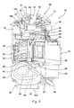
- Fig. 3 is a right side view of the power unit 19 of the electric motorcycle 1 of Fig. 1 .
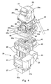
- Fig. 4 is an exploded perspective view of the power unit 19 (the motor unit 25 is not shown) of the electric motorcycle 1 of Fig. 1 , when viewed from leftward and forward.
- Fig. 5 is an exploded perspective view of the power unit 19 (the motor unit 25 is not shown) of the electric motorcycle 1 of Fig. 1 , when viewed from rightward and rearward.
- Fig. 6 is a longitudinal sectional view of the power unit 19 (the motor unit 25 is not shown) of the electric motorcycle 1 of Fig. 1 , when viewed from leftward. As shown in Figs.
- the plurality of batteries 40 storing a DC power to be supplied to the electric motor 42 are aligned in a battery space S2 in the interior of the battery case 20.
- the plurality of batteries 40 are integrated by a casing 41 as an assembly to form a battery group.
- the battery group is placed in such a manner that its front portion has a larger width than its rear portion in the vehicle width direction (rightward and leftward direction). This makes it possible to prevent an increase in the vertical dimension of the whole batteries 40, while increasing the capacity of the whole batteries 40.
- each of the middle case 21 and the upper case 22 is configured in such a manner that its front portion has a larger width than its rear portion. This allows the driver seated on the seat 30 to easily grip the battery case 20 with the legs.
- the rear region of the region of the middle case 21, which is surrounded by the frame member 32, is closed by a bottom plate 33 made of metal, which is fastened to the frame member 32 by welding, while the front region of the region of the middle case 21, which is surrounded by the frame member 32, forms an opening 32c which is in communication with the inner space of the lower case 23.
- the plurality of batteries 40 are accommodated such that they are placed on the frame member 32 and the bottom plate 33.
- the batteries 40 are also accommodated in the interior of the lower case 2.
- the middle case 21 and the upper case 22 constitute an upper battery accommodating section
- the lower case 23 constitutes a lower battery accommodating section.
- the lower case 23 as the lower battery accommodating section is shorter in length in the forward and rearward direction than the middle case 21 and the upper case 22 as the upper battery accommodating section are, and is connected to the front lower portion of the middle case 21.
- the motor unit 25 is placed immediately behind the lower case 23 and immediately below the middle case 21.
- the electric motor 42 is placed below the battery case.
- the electric motor 42 is placed below the rear portion of the battery case 20 and rearward relative to the front portion of the battery case 20.
- the front portion of the battery case 20 protrudes downward.
- the upper surface of the electric motor 42 is placed above the lowermost surface of the battery case 20.
- the front surface of the electric motor 42 is placed forward relative to the rearmost surface of the battery case 20. This allows the batteries 40 and the electric motor 42 to be close to each other, and the lower end of the battery case 20 to be located as low as possible. Since the terminal block of the electric motor 42 is placed below the upper surface of the batteries 40, at least a portion of an electric wire (power line) connecting the inverter 47 to the electric motor 42 runs through the interior of the battery case 20.
- the upper surface of the upper case 22 of the battery case 20 is formed with an electric component region 22a surrounded by a peripheral rib 22e.
- the electric component cover 26 is placed over the upper surface of the upper case 22 along the peripheral rib 22e, thereby forming an electric component space S1.
- the electric component cover 26 is formed with a recess 26a corresponding to a recess 28d of the upper cover 28.
- the electric component group 46 is placed in the electric component space S1.
- the electric component group 46 is placed above the batteries 40 to overlap with the batteries 40 when viewed from above.
- the electric component group 46 includes electric components associated with a high-voltage current of the batteries 40, through which the high-voltage current flows.
- the electric component group 46 includes at least one of the inverter 47 (switching device), a DC/DC converter 50 (transformer), a ground leakage sensor 51, a DC/DC converter relay 52, a varistor 53, a discharging relay 55, a charging relay 57, a fuse 59, a precharge resistor 60, and a service plug 71.
- the electric component group 46 includes all of the inverter 47, the DC/DC converter 50, the ground leakage sensor 51, the DC/DC converter relay 52, the varistor 53, the discharging relay 55, the charging relay 57, the fuse 59, the precharge resistor 60, and the service plug 71.
- the electric component group 46 may include electric components associated with a low-voltage current.
- the electric component group 46 includes a fan 48 and an ECU 54 (control device).
- the upper case 22 of the battery case 20 is provided with a seat section 22c protruding upward from the upper surface thereof, in a location that is rearward relative to the electric component cover 26.
- the charging connector 75 is mounted on the seat section 22c, to charge the batteries 40 with the electric power supplied externally. More specifically, the charging connector 75 is integrated with the battery case 20 outside of the battery case 20 to constitute a portion of the power unit 19. The charging connector 75 is placed above the batteries 40 to overlap with the batteries 40 when viewed from above.
- the rear wall portion of the electric component cover 26 is formed with an insertion hole 26c. The electric wire extending from the charging connector 75 is guided to the electric component space S1 through the insertion hole 26c.
- the charging connector 75 is provided with a connector connection surface 76 to which a power supply connector 90 of a L-shape connected to an outside power supply via a cable 91 is connected.
- the connector connection surface 76 faces in the vehicle width direction (in the present example, leftward).
- the connector connection surface 76 is provided with a quick charging connector 77 and a normal charging connector 78.
- the quick charging connector 77 and the normal charging connector 78 are arranged at upper and lower sides, respectively.
- the charging connector 75 is placed outward and rearward relative to the electric component cover 26 and inward relative to the upper cover 28 (see Fig. 1 ).
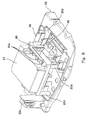
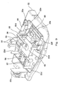
- Fig. 7 is a perspective view of the region above the battery case 20 of the electric motorcycle 1 of Fig. 1 , when viewed from rightward and forward.
- Fig. 8 is a perspective view showing a state in which the ECU 54, the DC/DC converter 50, and the like in the region above the battery case 20 of Fig. 7 are detached.
- Fig. 9 is a perspective view showing a state in which the inverter 47 and the like in the region above the battery case of Fig. 8 are further detached.
- the fan 48 is mounted to the center portion of the electric component region 22a provided in the upper surface of the upper case 22 of the battery case 20.
- the upper wall of the upper case 22 is formed with an air inlet 22g via which the electric component space S1 is in communication with the battery space S2.
- the fan 48 causes the air to flow from the interior of the electric component space S1 into the battery space S2 through the air inlet 22g.
- the upper case 22 is formed with a duct member 22f defining an air passage connecting the discharge outlet of the fan 48 to the air inlet 22g.
- the pair of discharging relays 55, 56 are mounted on a current supply path connecting the batteries 40 to the inverter 47, and the pair of charging relays 57, 58 are mounted on a current supply path connecting the charging connector 75 to the batteries 40.
- the fuse 59 provided in a power supply circuit and the precharge resistor 60 are mounted. From the electric component region 22, a plurality of support elements 22d on which the inverter 47 is to be mounted protrude upward.
- the electric component region 22 is provided with a pair of bus bar modules 81 which are the electric wires protruding upward and electrically connected to the batteries 40 via the discharging relays 55, 56, the fuse 59, the precharge resistor 60, and the like.
- a bus bar module 80 protrudes upward from the battery space S2 through an opening 22b formed in the electric component region 22.
- the bus bar module 80 includes three bus bars stacked together, insulatively bonded together and integrated, which are electric wires used to supply a three-phase AC current from the inverter 47 to the electric motor 42.
- the bus bar module 80 can be easily handled, and generation of a noise can be suppressed.
- the inverter 47 is mounted on the support elements 22d.
- the inverter 47 is placed above the upper case 22 with a gap from the upper surface of the upper case 22.
- the inverter 47 is configured to convert a DC power supplied from the batteries 40 (see Fig. 3 ) into an AC power and supply the AC power to the electric motor 42 (see Fig. 3 ), and includes a semiconductor switching element.
- the inverter 47 is placed above the batteries 40 to overlap with the battery case 20 when viewed from above.
- the inverter 47 is placed above the battery case 20 to be included within the battery case 20 when viewed from above.
- the inverter 47 has a flat shape in which a vertical dimension is smaller than a dimension in the forward and rearward direction and a dimension in the rightward and leftward direction.
- the inverter 47 is placed inward relative to the front and rear edges and right and left edges of the assembly of the battery case 20 and the batteries 40 when viewed from above.
- the inverter 47 is placed above the fan 48, the discharging relays 55, 56, and the charging relays 57, 58 to overlap with the fan 48, the discharging relays 55, 56, and the charging relays 57, 58 when viewed from above.
- the fan 48, the discharging relays 55, 56, and the charging relays 57, 58 are placed between the battery case 20 and the inverter 47.
- many electric components can be placed in the electric component region 22a with a small area, and the electric wires or the like connecting them to each other, and the electric wires or the like connecting them to the batteries 40, can be reduced in length.
- Three terminal sections 80a of the bus bar module 80 are connected to the output terminal of the inverter 47.
- the terminal sections of the bus bar modules 81 are connected to the input terminal of the inverter 47.
- a shield member 49 formed by bending a metal plate is placed over the inverter 47.
- the shield member 49 includes first leg elements 49d placed on the inverter 47 to correspond to some of the support elements 22d, respectively, a first horizontal wall portion 49c extending horizontally from the upper ends of the first leg elements 49d, a vertical wall portion 49b extending upward from the end portion of the first horizontal wall portion 49c, a second horizontal wall portion 49a extending horizontally from the upper end of the vertical wall portion 49b, and second leg elements 49e extending from the end portion of the second horizontal wall portion 49a and placed on the inverter 47 to correspond to the other support elements 22d, respectively.
- the shield member 49 has a step shape.
- the ground leakage sensor 51 On the upper surface of the first horizontal wall portion 49c, the ground leakage sensor 51, the DC/DC converter relay 52, and the varistor 53 are mounted.
- the ECU 54 for controlling the inverter 47, the relays 52, 55 to 58, etc. On the upper surface of the second horizontal wall portion 49a, the DC/DC converter 50 is mounted.
- the shield member 49 is interposed between the DC/DC converter 50 and the ECU 54 to isolate them from each other. In this structure, the shield member 49 shields an electromagnetic noise generated from the DC/DC converter 50 and the inverter 47 and thereby prevents the noise from being transmitted to the ECU 54.
- the electric components in the weak electric system are placed above the electric components in the strong electric system (the inverter, the DC/DC converter, etc.) with the metal plate interposed between the electric components in the weak electric system and the electric components in the strong electric system, space saving can be achieved while preventing the effects of the electromagnetic noise on the electric components in the weak electric system.
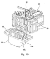
- Fig. 10 is a perspective view of major components for explaining the bus bar modules 80, 82 in the interior of the battery case 20 of the electric motorcycle 1 of Fig. 1 .
- the bus bar module 80 as the electric wire connecting the electric motor 42 (see Fig. 1 ) to the inverter 47 vertically runs through the internal space of the battery case 20 (see Fig. 4 ).
- Terminal sections 80b at the lower end portion of the bus bar module 80 are placed in a terminal accommodating section 23b of the lower case 23.
- three high-voltage electric cables 27 see Fig.
- the batteries 40 are interconnected in series by the bus bar module 82.
- the positive terminal and negative terminal of the battery group connected in series are connected to the buss bars 81 (see Fig. 9 ) provided in the electric component space to connect the battery group to the inverter 47.
- cooling medium passages (not shown) through which the oil as the cooling medium flows are provided, and the lower portion of the inverter 47 is provided with a cooling medium inlet 62 and a cooling medium outlet 63 which are in communication with the cooling medium passages.
- Cooling medium pipes 64, 65 are connected to the cooling medium inlet 62 and the cooling medium outlet 63, respectively.
- the cooling medium pipes 64, 65 penetrate the upper wall of the upper case 22 and run through the internal space of the battery case 20.
- the cooling medium pipes 64, 65 are connected to cooling medium pipes 67, 68, respectively, via a joint 66.
- the cooling medium pipe 67 is connected to the oil cooler 69, while the cooling medium pipe 68 is connected to the casing 44 of the motor unit 25.
- the oil flows into the casing 44 through the cooling medium pipe 68, cools or lubricates the electric motor 42 or the transmission 43, and then is gathered in the oil pan 44a.
- the oil accumulated in the oil pan 44a is suctioned up by the oil pump 45, and then is discharged to the oil cooler 69.
- the oil After flowing through the oil cooler 69, the oil is guided to the inverter 47 through the cooling medium pipes 67, 64.
- the cooling medium pipes 64, 65, 67, 68 are used to circulate the cooling medium to the motor unit 25 and to the inverter 47.
- cooling medium pipes 64, 65, 67, 68 vertically run through the internal space of the battery case 20 to circulate the cooling medium to cooling components (motor unit 25, oil pan 44a, oil pump 45, oil cooler 69, etc.) provided below battery case 20 and the inverter 47 provided above the battery case 20.
- cooling components motor unit 25, oil pan 44a, oil pump 45, oil cooler 69, etc.
- the inverter 47 since the inverter 47 is placed above the batteries 40 to overlap with the battery case 20, when viewed from above, the batteries 40 with a heavy weight are placed at a lower side to lower the center of gravity of the electric motorcycle 1, and it becomes less likely that water splashing from a road surface contacts the inverter 47. Therefore, the inverter 47 need not meet high water-proof requirements.
- the inverter 47 since the inverter 47 can be placed in the vicinity of the batteries 40, the electric wire (bus bar module) connecting the inverter 47 to the batteries 40 can be reduced in length. As a result, it becomes possible to reduce cost by reducing the water-proof requirements of the inverter, while lowering the center of gravity of the electric motorcycle 1.
- the inverter 47 is placed above the batteries 40 to overlap with the battery case 20 when viewed from above, and the motor unit 25 is placed below the batteries 40 to overlap with the battery case 20 when viewed from above. Therefore, the width of the vehicle body can be reduced, and an occupation space in the forward and rearward direction can be reduced.
- the batteries 40 and the inverter 47 are placed between the handle 6 and the seat 30, the center of gravity of the vehicle body is easily made closer to the center position of the vehicle body. Even when the inverter 47 and the batteries 40 are arranged at upper and lower sides, respectively, a driver can easily steer the electric motorcycle 1. Since the electric components (e.g., the discharging relays 55, 56, the fuse 59, the precharge resistor 60, etc.) provided on a conductive path between the inverter 47 and the batteries 40 are placed above the batteries 40, the batteries 40 and the inverter 47 can be made close to each other.
- the electric components e.g., the discharging relays 55, 56, the fuse 59, the precharge resistor 60, etc.
- the bus bar module 80 can be easily protected from an outside world and space efficiency can be increased. Since the inverter 47 and the electric motor 42 are arranged at upper and lower sides, respectively, with the batteries 40 interposed between the inverter 47 and the electric motor 42, and the cooling medium pipes 64, 65 used to circulate the cooling medium run through the internal space of the battery case 20, the cooling medium pipes 64, 65 can be easily protected from an outside world and space efficiency can be increased.
- the inverter 47 and the motor unit 25 are placed to close to each other in the forward and rearward direction, specifically, at upper and lower sides, respectively, with the battery case 20 interposed between the motor unit 25 and the inverter 47, the length of each of the cooling medium pipes 64, 65 in the forward and rearward direction can be reduced. Since the electric motor 42 is placed rearward relative to the lower case 23 (lower battery accommodating section) and below the middle case 21 (upper battery accommodating section), the center of gravity of the electric motorcycle 1 can be lowered. Even when the inverter 47 and the like are placed above the battery case 20, the vertical dimension of the electric motor 42, the batteries 40, the inverter 47, and the like, as a whole, is not increased, and therefore the driver's steering of the electric motorcycle 1 is not affected.
- the electric component group 46 including the inverter 47 is placed forward relative to the rear end of the entire of the plurality of batteries 40, there is a sufficient space between the vehicle body and the abdominal part of the driver seated on the seat 30 and gripping the handle 6. Therefore, the driver can drive the electric motorcycle 1 in a comfortable posture. Since the charging connector 75 is placed rearward relative to and adjacently to the electric component group 46, and is smaller in dimension in the vertical direction and in the vehicle width direction than the whole electric component group 46 is, the charging connector 75 can be placed in a compact manner while avoiding the driver from driving in a cramped posture. Since the charging connector 75 is placed in front of the seat 30, it becomes possible to prevent a situation in which the driver starts the electric motorcycle 1 in the state in which the power supply connector 90 is connected to the charging connector 75.
- Heat generated in the inverter 47 travels upward. Since the inverter 47 is placed above and fastened to the battery case 20, it becomes possible to prevent heat generated in the inverter 47 from being transferred to the batteries 40. Because of the vertical gap formed between the inverter 47 and the battery case 20, heat transfer to the batteries 40 can be prevented more effectively. Since the inverter 47 is covered by the cover (shield member 49) made of metal, from outward, the emission of the electromagnetic noise to outside of the electric motorcycle 1 can be suppressed.
- the cooling medium pipes are placed at an outward side in the vehicle width direction, which is an opposite side (in the present example, right side) of the side stand, with respect to the batteries. In this layout, even when the vehicle body falls to a left in a stopped state of the electric motorcycle 1, the cooling medium pipes do not contact an obstacle such as a road surface.
- the terminal block of the inverter 47 and the terminal block of the electric motor 42 are placed inward relative to the front, rear, right and left edges of the assembly of the batteries 40 and of the battery case 20, when viewed from above. Therefore, the electric wires can be placed inward relative to the contour of the battery case 20 to electrically connect the inverter 47 to the electric motor 42. Since the electric component group 46 is placed outside of the battery case 20, maintenance for the electric component group 46 can be carried out more easily without a need to open the battery case 20.
- the electric component group 46 Since the electric component group 46 is placed above the batteries 40, assembling can be carried out more easily than in a case where the electric components are placed below the batteries 40. Since the electric component group 46 including the inverter 47 is placed on the upper case 22 detachably mounted to the middle case 21, of the battery case 20, assembling can be carried out in a state in which the electric component group 46 is mounted to the battery case 20 as a sub-assembly. When the battery case 20 is detached from the vehicle body, the electric component group 46 can be detached from the vehicle body together with the batteries 40. This allows an operator to easily check the operation of the batteries 40 in the state in which the batteries 40 are detached from the vehicle body before or after shipping.
- the electric components including the inverter 47 may be placed in the interior of the battery case 20.
- the electric vehicle may be a three-wheeled vehicle or a four-wheeled vehicle, as well as the motorcycle.
- the electric wires and the cooling medium pipes may run through a region outside of the battery case 20. Or, either the electric wires or the cooling medium pipes may run through a region outside of the battery case 20.
- the cooling components placed below the battery case 20 may include, for example, at least one of a motor, a radiator (heat exchanger), a pump, an oil pan, a filter, etc.. Or, other cooling components placed below the battery case 20 may include a component to be cooled, other than the motor.
- the component to be cooled may include a functional component used for cooling the batteries, or a temperature sensor, a pressure sensor, etc.
- the cooling medium may be a liquid or a gas, and may be transformed into the gas or the liquid within the cooling medium pipes.
- the electric vehicle of the present invention can achieve an advantage that it becomes possible to reduce cost by reducing the water-proof requirements of the inverter, while lowering the center of gravity of the electric vehicle. Therefore, the electric vehicle of the present invention is widely applicable to a straddle-type vehicle, such as an electric motorcycle, etc., which can achieve this advantage.
Landscapes
- Engineering & Computer Science (AREA)
- Mechanical Engineering (AREA)
- Chemical & Material Sciences (AREA)
- Transportation (AREA)
- General Chemical & Material Sciences (AREA)
- Electrochemistry (AREA)
- Chemical Kinetics & Catalysis (AREA)
- Power Engineering (AREA)
- Combustion & Propulsion (AREA)
- Sustainable Energy (AREA)
- Sustainable Development (AREA)
- Life Sciences & Earth Sciences (AREA)
- Aviation & Aerospace Engineering (AREA)
- Electric Propulsion And Braking For Vehicles (AREA)
- Arrangement Or Mounting Of Propulsion Units For Vehicles (AREA)
Abstract
Description
- The present invention relates to an electric vehicle which drives a wheel with a driving power generated in an electric motor.
- In recent years, an electric vehicle which drives a wheel with a driving power generated in an electric motor using an electric power supplied from batteries has been developed. Patent Literature 1 discloses an electric motorcycle in which batteries are accommodated in a battery accommodating section placed below a seat, and an inverter is placed on a floor panel below the batteries.
- Patent Literature 1: Japanese Laid-Open Patent Application Publication No.
2011-234559 - In order to increase the cruising distance of the vehicle, it is necessary to increase the batteries in size. However, in the above configuration, the batteries are placed above electric components such as the inverter. Because of the layout of the batteries with a heavy weight, the center of gravity of a vehicle body is made higher. Since the inverter is placed at a relatively lower side, it is likely that water splashing from a road surface contacts the inverter, during driving of the electric vehicle. For this reason, the inverter is required to improve a water-proof property, which will increase cost.
- Accordingly, an object of the present invention is to reduce cost by reducing the water-proof requirements of the inverter while lowering the center of gravity of the electric vehicle.
- The present invention provides an electric vehicle comprising: an electric motor which generates a driving power for driving a wheel; a battery case accommodating a battery storing a DC power to be supplied to the electric motor, in a battery space in an interior of the battery case; and an inverter which converts the DC power supplied from the battery into an AC power and supplies the AC power to the electric motor, wherein the inverter is placed above the battery to overlap with the battery case when viewed from above.
- In accordance with this configuration, since the inverter is placed above the battery to overlap with the battery case when viewed from above, the battery with a heavy weight is placed at a lower side to lower the center of gravity of a vehicle body, and it becomes less likely that water splashing from a road surface contacts the inverter. Therefore, the inverter need not meet high water-proof requirements. In addition, since the inverter can be placed in the vicinity of the battery, an electric wire (power line) connecting the inverter to the battery can be reduced in length. As a result, it becomes possible to reduce cost by reducing the water-proof requirements of the inverter while lowering the center of gravity of the electric vehicle.
- The electric vehicle may be a straddle-type vehicle.
- In accordance with this configuration, since the inverter is placed above the battery to overlap with the battery case when viewed from above, in the straddle-type vehicle which is limited in the width of the vehicle body, the width of the vehicle body can be reduced.
- The electric vehicle may further comprise a handle; and a seat, wherein the battery and the inverter may be placed between the handle and the seat.
- In accordance with this configuration, since the center of gravity of the vehicle body is easily made close to the center of the vehicle body. Even when the inverter and the battery are arranged at upper and lower sides, respectively, a driver can easily steer the electric vehicle.
- The electric vehicle may further comprise an electric component provided on an electric wire connecting the inverter to the battery, and the electric component may be placed above the battery.
- In accordance with this configuration, the battery and the inverter can be made closer to each other.
- The electric motor may be provided at a lower side of the battery case, and an electric wire connecting the electric motor to the inverter may vertically run through an internal space of the battery case.
- In accordance with this configuration, since the electric wire connecting the electric motor to the inverter vertically runs through the internal space of the battery case, the electric wire can be easily protected from an outside world and space efficiency can be increased.
- The electric vehicle may further comprise a cooling medium pipe which circulates a cooling medium to the inverter, and the cooling medium pipe may run through an internal space of the battery case.
- In accordance with this configuration, since the cooling medium pipe runs through the internal space of the battery case, the cooling medium pipe can be easily protected from an outside world and space efficiency can be increased.
- The cooling medium pipe may run through an internal space of the battery case and circulate the cooling medium to a cooling component provided at a lower side of the battery case and to the inverter.
- In accordance with this configuration, since the inverter and the cooling component are arranged at upper and lower sides, respectively with the battery interposed between the inverter and the cooling component, and the cooling medium pipe vertically runs through the internal space of the battery case, the cooling medium pipe can be easily protected from an outside world and space efficiency can be increased. The cooling component may be, for example, at least one of a motor, a radiator, a pump, an oil pan, a filter, etc..
- The electric vehicle may be a motorcycle, and the electric motor and the battery case may be placed between a front wheel and a rear wheel, the battery case may include an upper battery accommodating section and a lower battery accommodating section which is shorter in a forward and rearward direction than the upper battery accommodating section is, the electric motor may be placed rearward relative to the lower battery accommodating section and below the upper battery accommodating section, and the inverter may be placed above the battery case.
- In accordance with this configuration, since the electric motor is placed rearward relative to the lower battery accommodating section and below the upper battery accommodating section, the center of gravity of the vehicle body can be lowered. Even when the inverter is placed above the battery case, the vertical dimension of the electric motor, the inverter and the battery, as a whole, is not increased, and therefore the driver's steering of the motorcycle is not affected.
- As should be appreciated from the above description, in accordance with the present invention, it becomes possible to reduce cost by reducing the water-proof requirements of the inverter, while lowering the center of gravity of the electric vehicle.
-
-
Fig. 1 is a left side view of an electric motorcycle according to an embodiment. -
Fig. 2 is a perspective view of a vehicle body frame of the electric motorcycle ofFig. 1 , when viewed from leftward and forward. -
Fig. 3 is a right side view of a power unit of the electric motorcycle ofFig. 1 . -
Fig. 4 is an exploded perspective view of the power unit (electric motor device is not shown) of the electric motorcycle ofFig. 1 , when viewed from leftward and forward. -
Fig. 5 is an exploded perspective view of the power unit (electric motor device is not shown) of the electric motorcycle ofFig. 1 , when viewed from rightward and rearward. -
Fig. 6 is a longitudinal sectional view of the power unit (electric motor device is not shown) of the electric motorcycle ofFig. 1 , when viewed from leftward. -
Fig. 7 is a perspective view of a region above a battery case of the electric motorcycle ofFig. 1 , when viewed from rightward and forward. -
Fig. 8 is a perspective view showing a state in which an ECU, a DC/DC converter and the like in the region above the battery case ofFig. 7 are detached. -
Fig. 9 is a perspective view showing a state in which an inverter and the like in the region above the battery case ofFig. 8 are further detached. -
Fig. 10 is a perspective view of major components for explaining bus bar modules in the interior of the battery case of the electric motorcycle ofFig. 1 . - Hereinafter, the embodiment will be described with reference to the drawings.
-
Fig. 1 is a left side view of an electric motorcycle 1 according to the embodiment of the present invention.Fig. 2 is a perspective view of avehicle body frame 10 of the electric motorcycle 1 ofFig. 1 , when viewed from leftward and forward. As shown inFig. 1 , the electric motorcycle 1 which is a straddle-type vehicle includes afront wheel 2 which is a driven wheel, and arear wheel 3 which is a drive wheel. Thefront wheel 2 is rotatably mounted to the lower end portion of afront fork 4. The upper portion of thefront fork 4 is integrated with a steering shaft (not shown). The steering shaft is rotatably supported by ahead pipe 5 of a vehicle body in a state in which the steering shaft is inserted into thehead pipe 5. A bar-type handle 6 extending in a rightward and leftward direction is attached to the steering shaft, and an accelerator grip (not shown) is provided at the right side of thehandle 6. - As shown in
Figs. 1 and2 , thevehicle body frame 10 of the electric motorcycle 1 includes a pair of right and leftmain frames 11 extending rearward from thehead pipe 5 such that they are inclined slightly downward. A pair of right and left downframes 14 are coupled to the front end portions of themain frames 11, respectively such that thedown frames 14 extend downward therefrom, and then rearward. The rear end portions of themain frames 11 are connected to the upper portion of apivot frame 12 of a frame shape. The front end portion of aswing arm 15 is mounted to thepivot frame 12 such that theswing arm 15 supports therear wheel 3 and is vertically pivotable. Arear frame 13 is placed above theswing arm 15 and is connected to the rear end portions of themain frames 11. - The
vehicle body frame 10 supports apower unit 19 in a space formed between thehead pipe 5 and thepivot frame 12. Thepower unit 19 includes a plurality ofbatteries 40, anelectric motor 42, an inverter 47 (seeFig. 3 ), and others which are integrated. The plurality ofbatteries 40 are accommodated into abattery case 20. Thebattery case 20 includes amiddle case 21 which has a tubular shape in which upper and lower sides thereof are opened, and the lower end of a rear section is closed, anupper case 22 attached to themiddle case 21 to close an upper opening in themiddle case 21, and alower case 23 attached to themiddle case 21 to close a lower opening in the front section of themiddle case 21. - The
middle case 21 includes acase body 31 of a rectangular tubular shape which is made of metal, and aframe member 32 which is provided inside of thecase body 31 and made of metal. Theframe member 32 is placed to extend horizontally in the lower portion of themiddle case 21. Thebatteries 40 accommodated in themiddle case 21 are supported from below by theframe member 32. Theframe member 32 of themiddle case 21 is fastened to the down frames 14. In other words, theframe member 32 made of metal which is a portion of thebattery case 20 constitutes a portion of thevehicle body frame 10. - A
motor unit 25 is mounted to thebattery case 20 in a location that is rearward relative to thelower case 23 and below themiddle case 21. Specifically, themotor unit 25 is fastened to theframe member 32 of themiddle case 21 and thepivot frame 12 bybrackets motor unit 25 includes acasing 44, theelectric motor 43 accommodated in thecasing 44 to generate a driving power for moving the vehicle body, atransmission 43 accommodated in thecasing 44 to change the speed of a rotational driving power output from theelectric motor 43, anoil pan 44a attached to the lower portion of thecasing 44, and anoil pump 45 which suctions up and discharges oil stored in theoil pan 44a. The rotational driving power output from thetransmission 43 is transmitted to therear wheel 3 via achain 16. - An
electric component cover 26 is attached to the upper surface of thebattery case 20 to form an electric component space accommodating anelectric component group 46, together with theupper case 22. Theelectric component cover 26 is insulative, and is made of, for example, an insulating resin material. Theelectric component cover 26 is covered by anupper cover 28 which is a dummy tank which looks like a fuel tank of a conventional engine-driven motorcycle. Theupper cover 22 is made of, for example, a metal material. Theelectric component cover 26 is lower in strength than theupper cover 28 is. The rear portion of theupper cover 28 is formed with aconnector opening 28 through which a charging connector 75 (seeFig. 5 ) which will be described later, is exposed. Theconnector opening 28 is closed by aconnector lid member 29. The rear portion of theupper cover 28, corresponding to theconnector lid member 29, is smaller in dimension in a vehicle width direction than the center portion of theupper cover 28, covering theelectric component cover 26. Adriver seat 30 supported by therear frame 13 is placed rearward relative to theupper cover 28. The driver seated on theseat 30 can grip theupper cover 28 with legs. The upper surface of thebattery case 20 is located below the upper end of theseat 30. In this configuration, even when theelectric component group 46 including theinverter 47 and the like is placed on thebattery case 20, it becomes possible to lessen the amount of theelectric component group 46 which protrudes upward from a virtual line connecting theseat 30 to thehead pipe 5. - The
batteries 40 are placed between thehead pipe 5 and theseat 30. At least a portion of thebatteries 40 is placed above and forward relative to foot steps of the vehicle body, and between the legs of the driver seated on theseat 30. Theelectric motor 42 is placed between thehead pipe 5 and theseat 30. Theelectric motor 42 is supported on thepivot frame 12 and is configured not to be pivoted together with theswing arm 15. -
Fig. 3 is a right side view of thepower unit 19 of the electric motorcycle 1 ofFig. 1 .Fig. 4 is an exploded perspective view of the power unit 19 (themotor unit 25 is not shown) of the electric motorcycle 1 ofFig. 1 , when viewed from leftward and forward.Fig. 5 is an exploded perspective view of the power unit 19 (themotor unit 25 is not shown) of the electric motorcycle 1 ofFig. 1 , when viewed from rightward and rearward.Fig. 6 is a longitudinal sectional view of the power unit 19 (themotor unit 25 is not shown) of the electric motorcycle 1 ofFig. 1 , when viewed from leftward. As shown inFigs. 3 to 6 , the plurality ofbatteries 40 storing a DC power to be supplied to theelectric motor 42 are aligned in a battery space S2 in the interior of thebattery case 20. The plurality ofbatteries 40 are integrated by acasing 41 as an assembly to form a battery group. The battery group is placed in such a manner that its front portion has a larger width than its rear portion in the vehicle width direction (rightward and leftward direction). This makes it possible to prevent an increase in the vertical dimension of thewhole batteries 40, while increasing the capacity of thewhole batteries 40. Correspondingly, each of themiddle case 21 and theupper case 22 is configured in such a manner that its front portion has a larger width than its rear portion. This allows the driver seated on theseat 30 to easily grip thebattery case 20 with the legs. - The rear region of the region of the
middle case 21, which is surrounded by theframe member 32, is closed by abottom plate 33 made of metal, which is fastened to theframe member 32 by welding, while the front region of the region of themiddle case 21, which is surrounded by theframe member 32, forms anopening 32c which is in communication with the inner space of thelower case 23. In the interior of themiddle case 21 and theupper case 22, the plurality ofbatteries 40 are accommodated such that they are placed on theframe member 32 and thebottom plate 33. Thebatteries 40 are also accommodated in the interior of thelower case 2. In other words, themiddle case 21 and theupper case 22 constitute an upper battery accommodating section, while thelower case 23 constitutes a lower battery accommodating section. Thelower case 23 as the lower battery accommodating section is shorter in length in the forward and rearward direction than themiddle case 21 and theupper case 22 as the upper battery accommodating section are, and is connected to the front lower portion of themiddle case 21. Themotor unit 25 is placed immediately behind thelower case 23 and immediately below themiddle case 21. - In other words, the
electric motor 42 is placed below the battery case. In the present embodiment, more specifically, theelectric motor 42 is placed below the rear portion of thebattery case 20 and rearward relative to the front portion of thebattery case 20. The front portion of thebattery case 20 protrudes downward. The upper surface of theelectric motor 42 is placed above the lowermost surface of thebattery case 20. The front surface of theelectric motor 42 is placed forward relative to the rearmost surface of thebattery case 20. This allows thebatteries 40 and theelectric motor 42 to be close to each other, and the lower end of thebattery case 20 to be located as low as possible. Since the terminal block of theelectric motor 42 is placed below the upper surface of thebatteries 40, at least a portion of an electric wire (power line) connecting theinverter 47 to theelectric motor 42 runs through the interior of thebattery case 20. - The upper surface of the
upper case 22 of thebattery case 20 is formed with anelectric component region 22a surrounded by aperipheral rib 22e. Theelectric component cover 26 is placed over the upper surface of theupper case 22 along theperipheral rib 22e, thereby forming an electric component space S1. Theelectric component cover 26 is formed with arecess 26a corresponding to a recess 28d of theupper cover 28. In the electric component space S1, theelectric component group 46 is placed. In other words, theelectric component group 46 is placed above thebatteries 40 to overlap with thebatteries 40 when viewed from above. Theelectric component group 46 includes electric components associated with a high-voltage current of thebatteries 40, through which the high-voltage current flows. For example, theelectric component group 46 includes at least one of the inverter 47 (switching device), a DC/DC converter 50 (transformer), aground leakage sensor 51, a DC/DC converter relay 52, avaristor 53, a dischargingrelay 55, a chargingrelay 57, afuse 59, aprecharge resistor 60, and aservice plug 71. In the present example, theelectric component group 46 includes all of theinverter 47, the DC/DC converter 50, theground leakage sensor 51, the DC/DC converter relay 52, thevaristor 53, the dischargingrelay 55, the chargingrelay 57, thefuse 59, theprecharge resistor 60, and theservice plug 71. Further, theelectric component group 46 may include electric components associated with a low-voltage current. In the present example, theelectric component group 46 includes afan 48 and an ECU 54 (control device). - The
upper case 22 of thebattery case 20 is provided with aseat section 22c protruding upward from the upper surface thereof, in a location that is rearward relative to theelectric component cover 26. The chargingconnector 75 is mounted on theseat section 22c, to charge thebatteries 40 with the electric power supplied externally. More specifically, the chargingconnector 75 is integrated with thebattery case 20 outside of thebattery case 20 to constitute a portion of thepower unit 19. The chargingconnector 75 is placed above thebatteries 40 to overlap with thebatteries 40 when viewed from above. The rear wall portion of theelectric component cover 26 is formed with aninsertion hole 26c. The electric wire extending from the chargingconnector 75 is guided to the electric component space S1 through theinsertion hole 26c. The chargingconnector 75 is provided with aconnector connection surface 76 to which apower supply connector 90 of a L-shape connected to an outside power supply via acable 91 is connected. Theconnector connection surface 76 faces in the vehicle width direction (in the present example, leftward). Theconnector connection surface 76 is provided with aquick charging connector 77 and anormal charging connector 78. Thequick charging connector 77 and thenormal charging connector 78 are arranged at upper and lower sides, respectively. The chargingconnector 75 is placed outward and rearward relative to theelectric component cover 26 and inward relative to the upper cover 28 (seeFig. 1 ). -
Fig. 7 is a perspective view of the region above thebattery case 20 of the electric motorcycle 1 ofFig. 1 , when viewed from rightward and forward.Fig. 8 is a perspective view showing a state in which theECU 54, the DC/DC converter 50, and the like in the region above thebattery case 20 ofFig. 7 are detached.Fig. 9 is a perspective view showing a state in which theinverter 47 and the like in the region above the battery case ofFig. 8 are further detached. As shown inFigs. 6 and9 , thefan 48 is mounted to the center portion of theelectric component region 22a provided in the upper surface of theupper case 22 of thebattery case 20. The upper wall of theupper case 22 is formed with anair inlet 22g via which the electric component space S1 is in communication with the battery space S2. Thefan 48 causes the air to flow from the interior of the electric component space S1 into the battery space S2 through theair inlet 22g. Theupper case 22 is formed with aduct member 22f defining an air passage connecting the discharge outlet of thefan 48 to theair inlet 22g. - As shown in
Fig. 9 , in a region of theelectric component region 22, the pair of dischargingrelays batteries 40 to theinverter 47, and the pair of chargingrelays connector 75 to thebatteries 40. In another region of theelectric component region 22, thefuse 59 provided in a power supply circuit and theprecharge resistor 60 are mounted. From theelectric component region 22, a plurality ofsupport elements 22d on which theinverter 47 is to be mounted protrude upward. Theelectric component region 22 is provided with a pair ofbus bar modules 81 which are the electric wires protruding upward and electrically connected to thebatteries 40 via the discharging relays 55, 56, thefuse 59, theprecharge resistor 60, and the like. Abus bar module 80 protrudes upward from the battery space S2 through anopening 22b formed in theelectric component region 22. Thebus bar module 80 includes three bus bars stacked together, insulatively bonded together and integrated, which are electric wires used to supply a three-phase AC current from theinverter 47 to theelectric motor 42. Thus, thebus bar module 80 can be easily handled, and generation of a noise can be suppressed. - As shown in
Fig. 8 , theinverter 47 is mounted on thesupport elements 22d. Theinverter 47 is placed above theupper case 22 with a gap from the upper surface of theupper case 22. Theinverter 47 is configured to convert a DC power supplied from the batteries 40 (seeFig. 3 ) into an AC power and supply the AC power to the electric motor 42 (seeFig. 3 ), and includes a semiconductor switching element. Theinverter 47 is placed above thebatteries 40 to overlap with thebattery case 20 when viewed from above. Theinverter 47 is placed above thebattery case 20 to be included within thebattery case 20 when viewed from above. Theinverter 47 has a flat shape in which a vertical dimension is smaller than a dimension in the forward and rearward direction and a dimension in the rightward and leftward direction. Theinverter 47 is placed inward relative to the front and rear edges and right and left edges of the assembly of thebattery case 20 and thebatteries 40 when viewed from above. - The
inverter 47 is placed above thefan 48, the discharging relays 55, 56, and the charging relays 57, 58 to overlap with thefan 48, the discharging relays 55, 56, and the charging relays 57, 58 when viewed from above. In other words, thefan 48, the discharging relays 55, 56, and the charging relays 57, 58 are placed between thebattery case 20 and theinverter 47. In this structure, many electric components can be placed in theelectric component region 22a with a small area, and the electric wires or the like connecting them to each other, and the electric wires or the like connecting them to thebatteries 40, can be reduced in length. Threeterminal sections 80a of thebus bar module 80 are connected to the output terminal of theinverter 47. Although not shown, the terminal sections of the bus bar modules 81 (seeFig. 9 ) are connected to the input terminal of theinverter 47. - As shown in
Figs. 6 and7 , ashield member 49 formed by bending a metal plate is placed over theinverter 47. Theshield member 49 includesfirst leg elements 49d placed on theinverter 47 to correspond to some of thesupport elements 22d, respectively, a firsthorizontal wall portion 49c extending horizontally from the upper ends of thefirst leg elements 49d, avertical wall portion 49b extending upward from the end portion of the firsthorizontal wall portion 49c, a secondhorizontal wall portion 49a extending horizontally from the upper end of thevertical wall portion 49b, andsecond leg elements 49e extending from the end portion of the secondhorizontal wall portion 49a and placed on theinverter 47 to correspond to theother support elements 22d, respectively. Thus, theshield member 49 has a step shape. - On the upper surface of the first
horizontal wall portion 49c, theground leakage sensor 51, the DC/DC converter relay 52, and thevaristor 53 are mounted. On the upper surface of the secondhorizontal wall portion 49a, theECU 54 for controlling theinverter 47, therelays horizontal wall portion 49a, the DC/DC converter 50 is mounted. In other words, theshield member 49 is interposed between the DC/DC converter 50 and theECU 54 to isolate them from each other. In this structure, theshield member 49 shields an electromagnetic noise generated from the DC/DC converter 50 and theinverter 47 and thereby prevents the noise from being transmitted to theECU 54. In other words, since the electric components in the weak electric system (the ECU, the sensors, etc.) are placed above the electric components in the strong electric system (the inverter, the DC/DC converter, etc.) with the metal plate interposed between the electric components in the weak electric system and the electric components in the strong electric system, space saving can be achieved while preventing the effects of the electromagnetic noise on the electric components in the weak electric system. -
Fig. 10 is a perspective view of major components for explaining thebus bar modules battery case 20 of the electric motorcycle 1 ofFig. 1 . As shown inFigs. 4 and10 , thebus bar module 80 as the electric wire connecting the electric motor 42 (seeFig. 1 ) to theinverter 47 vertically runs through the internal space of the battery case 20 (seeFig. 4 ).Terminal sections 80b at the lower end portion of thebus bar module 80 are placed in a terminalaccommodating section 23b of thelower case 23. Between theterminal sections 80b in theterminal accommodating section 23b and the terminal section (not shown) of theelectric motor 42, three high-voltage electric cables 27 (seeFig. 1 ) are placed to couple the terminal sections in a location outside of thebattery case 20. In this case, since thelower case 23 including theterminal accommodating section 23b and theelectric motor 42 are adjacent to each other in the forward and rearward direction, the high-voltageelectric cables 27 exposed to outside can be reduced in length. As shown inFig. 10 , thebatteries 40 are interconnected in series by thebus bar module 82. The positive terminal and negative terminal of the battery group connected in series are connected to the buss bars 81 (seeFig. 9 ) provided in the electric component space to connect the battery group to theinverter 47. - Turning back to
Fig. 3 , in the interior of the casing of theinverter 47, cooling medium passages (not shown) through which the oil as the cooling medium flows are provided, and the lower portion of theinverter 47 is provided with a coolingmedium inlet 62 and a coolingmedium outlet 63 which are in communication with the cooling medium passages. Coolingmedium pipes medium inlet 62 and the coolingmedium outlet 63, respectively. The coolingmedium pipes upper case 22 and run through the internal space of thebattery case 20. The coolingmedium pipes medium pipes medium pipe 67 is connected to theoil cooler 69, while the coolingmedium pipe 68 is connected to thecasing 44 of themotor unit 25. The oil flows into thecasing 44 through the coolingmedium pipe 68, cools or lubricates theelectric motor 42 or thetransmission 43, and then is gathered in theoil pan 44a. The oil accumulated in theoil pan 44a is suctioned up by theoil pump 45, and then is discharged to theoil cooler 69. After flowing through theoil cooler 69, the oil is guided to theinverter 47 through the coolingmedium pipes medium pipes motor unit 25 and to theinverter 47. Specifically, the coolingmedium pipes battery case 20 to circulate the cooling medium to cooling components (motor unit 25,oil pan 44a,oil pump 45,oil cooler 69, etc.) provided belowbattery case 20 and theinverter 47 provided above thebattery case 20. - In accordance with the above described configuration, since the
inverter 47 is placed above thebatteries 40 to overlap with thebattery case 20, when viewed from above, thebatteries 40 with a heavy weight are placed at a lower side to lower the center of gravity of the electric motorcycle 1, and it becomes less likely that water splashing from a road surface contacts theinverter 47. Therefore, theinverter 47 need not meet high water-proof requirements. In addition, since theinverter 47 can be placed in the vicinity of thebatteries 40, the electric wire (bus bar module) connecting theinverter 47 to thebatteries 40 can be reduced in length. As a result, it becomes possible to reduce cost by reducing the water-proof requirements of the inverter, while lowering the center of gravity of the electric motorcycle 1. - In the electric motorcycle 1 which is limited in the width of the vehicle body, the
inverter 47 is placed above thebatteries 40 to overlap with thebattery case 20 when viewed from above, and themotor unit 25 is placed below thebatteries 40 to overlap with thebattery case 20 when viewed from above. Therefore, the width of the vehicle body can be reduced, and an occupation space in the forward and rearward direction can be reduced. - Since the
batteries 40 and theinverter 47 are placed between thehandle 6 and theseat 30, the center of gravity of the vehicle body is easily made closer to the center position of the vehicle body. Even when theinverter 47 and thebatteries 40 are arranged at upper and lower sides, respectively, a driver can easily steer the electric motorcycle 1. Since the electric components (e.g., the discharging relays 55, 56, thefuse 59, theprecharge resistor 60, etc.) provided on a conductive path between theinverter 47 and thebatteries 40 are placed above thebatteries 40, thebatteries 40 and theinverter 47 can be made close to each other. - Since the
inverter 47 and theelectric motor 42 are arranged at upper and lower sides, respectively, with thebatteries 40 interposed between theinverter 47 and theelectric motor 42, and thebus bar module 80 electrically connecting theinverter 47 to theelectric motor 42 vertically runs through the internal space of thebattery case 20, thebus bar module 80 can be easily protected from an outside world and space efficiency can be increased. Since theinverter 47 and theelectric motor 42 are arranged at upper and lower sides, respectively, with thebatteries 40 interposed between theinverter 47 and theelectric motor 42, and the coolingmedium pipes battery case 20, the coolingmedium pipes - Since the
inverter 47 and themotor unit 25 are placed to close to each other in the forward and rearward direction, specifically, at upper and lower sides, respectively, with thebattery case 20 interposed between themotor unit 25 and theinverter 47, the length of each of the coolingmedium pipes electric motor 42 is placed rearward relative to the lower case 23 (lower battery accommodating section) and below the middle case 21 (upper battery accommodating section), the center of gravity of the electric motorcycle 1 can be lowered. Even when theinverter 47 and the like are placed above thebattery case 20, the vertical dimension of theelectric motor 42, thebatteries 40, theinverter 47, and the like, as a whole, is not increased, and therefore the driver's steering of the electric motorcycle 1 is not affected. - Since the
electric component group 46 including theinverter 47 is placed forward relative to the rear end of the entire of the plurality ofbatteries 40, there is a sufficient space between the vehicle body and the abdominal part of the driver seated on theseat 30 and gripping thehandle 6. Therefore, the driver can drive the electric motorcycle 1 in a comfortable posture. Since the chargingconnector 75 is placed rearward relative to and adjacently to theelectric component group 46, and is smaller in dimension in the vertical direction and in the vehicle width direction than the wholeelectric component group 46 is, the chargingconnector 75 can be placed in a compact manner while avoiding the driver from driving in a cramped posture. Since the chargingconnector 75 is placed in front of theseat 30, it becomes possible to prevent a situation in which the driver starts the electric motorcycle 1 in the state in which thepower supply connector 90 is connected to the chargingconnector 75. - Heat generated in the
inverter 47 travels upward. Since theinverter 47 is placed above and fastened to thebattery case 20, it becomes possible to prevent heat generated in theinverter 47 from being transferred to thebatteries 40. Because of the vertical gap formed between theinverter 47 and thebattery case 20, heat transfer to thebatteries 40 can be prevented more effectively. Since theinverter 47 is covered by the cover (shield member 49) made of metal, from outward, the emission of the electromagnetic noise to outside of the electric motorcycle 1 can be suppressed. - Since the middle case is made of metal, the electric wires and the cooling medium pipes can be protected more effectively. The cooling medium pipes are placed at an outward side in the vehicle width direction, which is an opposite side (in the present example, right side) of the side stand, with respect to the batteries. In this layout, even when the vehicle body falls to a left in a stopped state of the electric motorcycle 1, the cooling medium pipes do not contact an obstacle such as a road surface.
- The terminal block of the
inverter 47 and the terminal block of theelectric motor 42 are placed inward relative to the front, rear, right and left edges of the assembly of thebatteries 40 and of thebattery case 20, when viewed from above. Therefore, the electric wires can be placed inward relative to the contour of thebattery case 20 to electrically connect theinverter 47 to theelectric motor 42. Since theelectric component group 46 is placed outside of thebattery case 20, maintenance for theelectric component group 46 can be carried out more easily without a need to open thebattery case 20. - Since the
electric component group 46 is placed above thebatteries 40, assembling can be carried out more easily than in a case where the electric components are placed below thebatteries 40. Since theelectric component group 46 including theinverter 47 is placed on theupper case 22 detachably mounted to themiddle case 21, of thebattery case 20, assembling can be carried out in a state in which theelectric component group 46 is mounted to thebattery case 20 as a sub-assembly. When thebattery case 20 is detached from the vehicle body, theelectric component group 46 can be detached from the vehicle body together with thebatteries 40. This allows an operator to easily check the operation of thebatteries 40 in the state in which thebatteries 40 are detached from the vehicle body before or after shipping. - The electric components including the
inverter 47 may be placed in the interior of thebattery case 20. The electric vehicle may be a three-wheeled vehicle or a four-wheeled vehicle, as well as the motorcycle. The electric wires and the cooling medium pipes may run through a region outside of thebattery case 20. Or, either the electric wires or the cooling medium pipes may run through a region outside of thebattery case 20. The cooling components placed below thebattery case 20 may include, for example, at least one of a motor, a radiator (heat exchanger), a pump, an oil pan, a filter, etc.. Or, other cooling components placed below thebattery case 20 may include a component to be cooled, other than the motor. For example, the component to be cooled may include a functional component used for cooling the batteries, or a temperature sensor, a pressure sensor, etc.. The cooling medium may be a liquid or a gas, and may be transformed into the gas or the liquid within the cooling medium pipes. The present invention is not limited to the above described embodiment, and its configuration can be changed, added or deleted within the scope of the invention. - As described above, the electric vehicle of the present invention can achieve an advantage that it becomes possible to reduce cost by reducing the water-proof requirements of the inverter, while lowering the center of gravity of the electric vehicle. Therefore, the electric vehicle of the present invention is widely applicable to a straddle-type vehicle, such as an electric motorcycle, etc., which can achieve this advantage.
-
- 1
- electric motorcycle (electric vehicle)
- 2
- front wheel
- 3
- rear wheel
- 6
- handle
- 20
- battery case
- 21
- middle case (upper battery accommodating section)
- 22
- upper case (upper battery accommodating section)
- 23
- lower case (lower battery accommodating section)
- 30
- seat
- 40
- battery
- 42
- electric motor
- 46
- electric component group
- 47
- inverter
- 65, 66
- cooling medium pipe
- 80
- bus bar module (electric wire)
Claims (8)
- An electric vehicle comprising:an electric motor which generates a driving power for driving a wheel;a battery case accommodating a battery storing a DC power to be supplied to the electric motor, in a battery space in an interior of the battery case; andan inverter which converts the DC power supplied from the battery into an AC power and supplies the AC power to the electric motor,wherein the inverter is placed above the battery to overlap with the battery case when viewed from above.
- The electric vehicle according to claim 1, being a straddle-type vehicle.
- The electric vehicle according to claim 2, further comprising
a handle; and
a seat,
wherein the battery and the inverter are placed between the handle and the seat. - The electric vehicle according to any one of claims 1 to 3, further comprising:an electric component provided on an electric wire connecting the inverter to the battery,wherein the electric component is placed above the battery.
- The electric vehicle according to any one of claims 1 to 4,
wherein the electric motor is provided at a lower side of the battery case, and
wherein an electric wire connecting the electric motor to the inverter vertically runs through an internal space of the battery case. - The electric vehicle according to any one of claims 1 to 5, further comprising:a cooling medium pipe which circulates a cooling medium to the inverter,wherein the cooling medium pipe runs through an internal space of the battery case.
- The electric vehicle according to claim 6,
wherein the cooling medium pipe vertically runs through the internal space of the battery case and circulates the cooling medium to a cooling component provided at a lower side of the battery case and to the inverter. - The electric vehicle according to any one of claims 1 to 7,
wherein the electric vehicle is a motorcycle, and
wherein the electric motor and the battery case are placed between a front wheel and a rear wheel,
wherein the battery case includes an upper battery accommodating section and a lower battery accommodating section which is shorter in a forward and rearward direction than the upper battery accommodating section is,
wherein the electric motor is placed rearward relative to the lower battery accommodating section and below the upper battery accommodating section, and
wherein the inverter is placed above the battery case.
Applications Claiming Priority (1)
| Application Number | Priority Date | Filing Date | Title |
|---|---|---|---|
| PCT/JP2012/008248 WO2014102851A1 (en) | 2012-12-25 | 2012-12-25 | Electric vehicle |
Publications (3)
| Publication Number | Publication Date |
|---|---|
| EP2939911A1 true EP2939911A1 (en) | 2015-11-04 |
| EP2939911A4 EP2939911A4 (en) | 2016-09-28 |
| EP2939911B1 EP2939911B1 (en) | 2017-10-11 |
Family
ID=51020018
Family Applications (1)
| Application Number | Title | Priority Date | Filing Date |
|---|---|---|---|
| EP12890809.2A Active EP2939911B1 (en) | 2012-12-25 | 2012-12-25 | Electric vehicle |
Country Status (5)
| Country | Link |
|---|---|
| US (1) | US9868490B2 (en) |
| EP (1) | EP2939911B1 (en) |
| JP (1) | JP5970562B2 (en) |
| CN (1) | CN104884343B (en) |
| WO (1) | WO2014102851A1 (en) |
Cited By (3)
| Publication number | Priority date | Publication date | Assignee | Title |
|---|---|---|---|---|
| EP3537502A1 (en) * | 2018-03-08 | 2019-09-11 | Yamaha Hatsudoki Kabushiki Kaisha | Leaning vehicle battery and leaning vehicle |
| CN111315645A (en) * | 2017-09-29 | 2020-06-19 | 本田技研工业株式会社 | Storage battery storage device for electric vehicle |
| US11390350B2 (en) * | 2018-08-07 | 2022-07-19 | Harley-Davidson Motor Company Group, LLC | Seat caddy for charging cable |
Families Citing this family (35)
| Publication number | Priority date | Publication date | Assignee | Title |
|---|---|---|---|---|
| US10011323B2 (en) * | 2012-12-25 | 2018-07-03 | Kawasaki Jukogyo Kabushiki Kaisha | Electric vehicle |
| CN104853979B (en) * | 2012-12-25 | 2018-01-16 | 川崎重工业株式会社 | Electric vehicle |
| CN107250823B (en) * | 2014-11-04 | 2020-10-30 | Cps科技控股有限公司 | Scalable Modular Design of a 48-Volt Li-Ion Battery Management System |
| JP6121391B2 (en) * | 2014-12-01 | 2017-04-26 | 本田技研工業株式会社 | Saddle riding type electric vehicle |
| JP6168098B2 (en) * | 2015-05-14 | 2017-07-26 | 小野塚精機株式会社 | Electric motorcycle |
| JP6561770B2 (en) * | 2015-10-27 | 2019-08-21 | スズキ株式会社 | Electric vehicle structure |
| WO2018033880A2 (en) | 2016-08-17 | 2018-02-22 | Shape Corp. | Battery support and protection structure for a vehicle |
| EP3566253B1 (en) | 2017-01-04 | 2022-12-28 | Shape Corp. | Battery support structure for a vehicle |
| US11211656B2 (en) | 2017-05-16 | 2021-12-28 | Shape Corp. | Vehicle battery tray with integrated battery retention and support feature |
| US10886513B2 (en) | 2017-05-16 | 2021-01-05 | Shape Corp. | Vehicle battery tray having tub-based integration |
| US10483510B2 (en) | 2017-05-16 | 2019-11-19 | Shape Corp. | Polarized battery tray for a vehicle |
| WO2019049462A1 (en) * | 2017-09-11 | 2019-03-14 | 本田技研工業株式会社 | Electric motorcycle |
| WO2019055658A2 (en) | 2017-09-13 | 2019-03-21 | Shape Corp. | Vehicle battery tray with tubular peripheral wall |
| US12347879B2 (en) | 2017-09-13 | 2025-07-01 | Shape Corp. | Vehicle battery tray with tubular peripheral wall |
| US10661646B2 (en) | 2017-10-04 | 2020-05-26 | Shape Corp. | Battery tray floor assembly for electric vehicles |
| CN112055898A (en) | 2018-03-01 | 2020-12-08 | 形状集团 | Cooling system integrated with vehicle battery tray |
| US11688910B2 (en) | 2018-03-15 | 2023-06-27 | Shape Corp. | Vehicle battery tray having tub-based component |
| WO2019210242A1 (en) * | 2018-04-27 | 2019-10-31 | FUELL Inc. | Electric saddle type vehicle chassis |
| US11753101B2 (en) | 2018-04-27 | 2023-09-12 | FUELL Inc. | Electric saddle type vehicle with storage areas |
| CN108394506A (en) * | 2018-05-04 | 2018-08-14 | 苏州柯谱瑞欣通信科技有限公司 | A kind of wireless cruise monitoring vehicle |
| WO2020067280A1 (en) * | 2018-09-28 | 2020-04-02 | 日本電産株式会社 | Motor unit |
| WO2020141542A1 (en) * | 2019-01-02 | 2020-07-09 | Tvs Motor Company Limited | Separate wire harness arrangement for high and low voltage. |
| WO2020176858A2 (en) | 2019-02-28 | 2020-09-03 | FUELL Inc. | Electric saddle type vehicle |
| US12101003B2 (en) * | 2019-04-11 | 2024-09-24 | Nidec Corporation | Motor with inverter and bus bar arrangement |
| US11821173B2 (en) * | 2019-09-25 | 2023-11-21 | Caterpillar Inc. | Inverter location and orientation within a mobile machine |
| CN112849315B (en) * | 2020-11-10 | 2022-08-16 | 浙江春风动力股份有限公司 | Electric motorcycle with stable structure |
| US11524780B2 (en) * | 2021-01-07 | 2022-12-13 | Faruk Hossain | Fan powered folding wing bicycle apparatus |
| EP4378732A4 (en) * | 2021-07-30 | 2025-07-23 | Yamaha Motor Co Ltd | ELECTRIC VEHICLE |
| US20230103828A1 (en) * | 2021-10-01 | 2023-04-06 | Kawasaki Motors, Ltd. | Saddle riding vehicle |
| JP2023092281A (en) * | 2021-12-21 | 2023-07-03 | ヤマハ発動機株式会社 | vehicle |
| JP7660496B2 (en) * | 2021-12-24 | 2025-04-11 | 株式会社クボタ | Electric work vehicle |
| JP7781914B2 (en) * | 2021-12-28 | 2025-12-08 | Astemo株式会社 | Electric drive unit |
| JP2024015970A (en) * | 2022-07-25 | 2024-02-06 | カワサキモータース株式会社 | Straddle electric vehicle |
| JP2025042488A (en) * | 2023-09-14 | 2025-03-27 | ヤンマーホールディングス株式会社 | Electrical work machinery |
| CN117227878B (en) * | 2023-09-15 | 2026-04-10 | 常州浩万新能源科技有限公司 | Thermal management system, thermal module and electric motorcycle |
Family Cites Families (54)
| Publication number | Priority date | Publication date | Assignee | Title |
|---|---|---|---|---|
| JP2945094B2 (en) * | 1990-08-02 | 1999-09-06 | 本田技研工業株式会社 | Electric motorcycle |
| JP3055185B2 (en) * | 1991-01-31 | 2000-06-26 | スズキ株式会社 | Battery mounting device for electric tricycle |
| EP0687588B1 (en) * | 1991-09-03 | 1999-01-07 | Honda Giken Kogyo Kabushiki Kaisha | Regenerative braking system in a motor vehicle |
| JPH05193367A (en) | 1992-01-16 | 1993-08-03 | Honda Motor Co Ltd | Battery box for electric vehicle |
| JPH06199146A (en) * | 1992-11-12 | 1994-07-19 | Honda Motor Co Ltd | Electric vehicle controller |
| JP3159814B2 (en) | 1992-12-24 | 2001-04-23 | キヤノン株式会社 | Ink jet recording device |
| EP0808738B1 (en) * | 1995-09-18 | 2003-06-11 | Seiko Epson Corporation | Safety mechanism for electric vehicle |
| JP3823586B2 (en) * | 1999-02-25 | 2006-09-20 | スズキ株式会社 | Electric vehicle |
| JP4032723B2 (en) * | 2001-12-06 | 2008-01-16 | 松下電器産業株式会社 | Air conditioner |
| JP4377561B2 (en) * | 2001-12-20 | 2009-12-02 | 本田技研工業株式会社 | Electric vehicle power unit structure |
| JP3867060B2 (en) * | 2003-03-28 | 2007-01-10 | 三菱電機株式会社 | Vehicle power supply system |
| US20060158890A1 (en) * | 2004-06-07 | 2006-07-20 | Freedman Paul H | Vehicle lighting system and isolation system therefor |
| JP4498856B2 (en) * | 2004-08-19 | 2010-07-07 | 本田技研工業株式会社 | Hydrogen filling port arrangement structure in fuel cell vehicle |
| JP4684598B2 (en) * | 2004-08-20 | 2011-05-18 | 本田技研工業株式会社 | Suspension device in fuel cell vehicle |
| EP1710155B1 (en) * | 2005-04-04 | 2008-08-13 | HONDA MOTOR CO., Ltd. | Motorcycle with fuel cell |
| JP4884818B2 (en) * | 2006-03-31 | 2012-02-29 | 川崎重工業株式会社 | Motorcycle |
| JP4434181B2 (en) * | 2006-07-21 | 2010-03-17 | 株式会社日立製作所 | Power converter |
| JP4277046B2 (en) * | 2007-02-28 | 2009-06-10 | トヨタ自動車株式会社 | Cooling device for internal combustion engine |
| JP5052922B2 (en) * | 2007-03-12 | 2012-10-17 | 本田技研工業株式会社 | Motorcycle |
| JP2010100124A (en) * | 2008-10-22 | 2010-05-06 | Yamaha Motor Co Ltd | Hybrid striding type vehicle |
| US8333626B2 (en) * | 2009-03-26 | 2012-12-18 | Suzuki Motor Corporation | Hybrid outboard motor |
| US8298023B2 (en) * | 2009-03-26 | 2012-10-30 | Suzuki Motor Corporation | Hybrid outboard motor |
| JP5206563B2 (en) * | 2009-04-15 | 2013-06-12 | 日産自動車株式会社 | Electric vehicle wiring structure |
| JP5597376B2 (en) * | 2009-09-15 | 2014-10-01 | 本田技研工業株式会社 | Motorcycle |
| JP5252311B2 (en) * | 2009-09-25 | 2013-07-31 | スズキ株式会社 | Hybrid vehicle cooling system |
| JP2011073536A (en) * | 2009-09-30 | 2011-04-14 | Hitachi Ltd | Thermodynamic cycle system for moving vehicle |
| WO2012059959A1 (en) * | 2010-11-05 | 2012-05-10 | 川崎重工業株式会社 | Saddled electric vehicle |
| JP3159814U (en) | 2010-03-16 | 2010-06-03 | ヤマハ発動機株式会社 | Hybrid straddle-type vehicle |
| JP2011234559A (en) | 2010-04-28 | 2011-11-17 | Sanyo Electric Co Ltd | Inverter device and electric vehicle loaded with the same |
| EP2623406B1 (en) | 2010-09-30 | 2017-01-18 | Honda Motor Co., Ltd. | Scooter-type electric vehicle |
| JP2012091595A (en) * | 2010-10-25 | 2012-05-17 | Honda Motor Co Ltd | Saddle-ride type electric vehicle |
| JP5595228B2 (en) * | 2010-10-29 | 2014-09-24 | 本田技研工業株式会社 | Electric vehicle |
| JP5595227B2 (en) * | 2010-10-29 | 2014-09-24 | 本田技研工業株式会社 | Electric motorcycle |
| US20130264134A1 (en) * | 2010-11-12 | 2013-10-10 | Kawasaki Jukogyo Kabushiki Kaisha | Mounting Structure of Electricity Storage Device in Electric Vehicle |
| US20130229072A1 (en) * | 2010-11-12 | 2013-09-05 | Kawasaki Jukogyo Kabushiki Kaisha | Cooling Structure for Cooling Electric Motor for Vehicle |
| EP2639941B1 (en) * | 2010-11-12 | 2019-04-03 | Kawasaki Jukogyo Kabushiki Kaisha | Cooling structure for electric vehicle |
| US8789640B2 (en) * | 2010-11-18 | 2014-07-29 | Kawasaki Jukogyo Kabushiki Kaisha | Electric motorcycle |
| US9132878B2 (en) * | 2010-11-18 | 2015-09-15 | Kawasaki Jukogyo Kabushiki Kaisha | Electric motorcycle |
| EP2657115B1 (en) * | 2010-12-24 | 2018-01-31 | Kawasaki Jukogyo Kabushiki Kaisha | Electric motorcycle |
| JP5504354B2 (en) * | 2010-12-27 | 2014-05-28 | 川崎重工業株式会社 | Straddle-type electric vehicle |
| JP5479613B2 (en) * | 2010-12-27 | 2014-04-23 | 川崎重工業株式会社 | Straddle-type electric vehicle |
| WO2012090246A1 (en) * | 2010-12-27 | 2012-07-05 | 川崎重工業株式会社 | Saddle-type electric vehicle and structure for mounting power controller in said electric vehicle |
| JP5536909B2 (en) * | 2010-12-27 | 2014-07-02 | 川崎重工業株式会社 | Electric motorcycle |
| WO2012090255A1 (en) * | 2010-12-28 | 2012-07-05 | 川崎重工業株式会社 | Electric-vehicle start assist method and start assist system |
| JP5553935B2 (en) * | 2011-03-31 | 2014-07-23 | 本田技研工業株式会社 | Electric vehicle control device |
| EP2708457B1 (en) * | 2011-05-13 | 2017-01-18 | Kawasaki Jukogyo Kabushiki Kaisha | Electric motorcycle, vehicle controller and vehicle control method |
| CN103781656B (en) * | 2011-10-24 | 2016-08-17 | 川崎重工业株式会社 | Electric vehicle |
| CN103987562B (en) * | 2011-12-26 | 2016-06-08 | 川崎重工业株式会社 | The diagnostic method of the electrodynamic type vehicles and system |
| JP5889339B2 (en) * | 2011-12-28 | 2016-03-22 | 川崎重工業株式会社 | Straddle-type electric vehicle |
| US9278725B2 (en) * | 2011-12-28 | 2016-03-08 | Kawasaki Jukogyo Kabushiki Kaisha | Straddle electric vehicle |
| EP2910400B1 (en) * | 2012-10-22 | 2020-03-25 | Kawasaki Jukogyo Kabushiki Kaisha | Regenerative brake control system of electric vehicle |
| EP2910401B1 (en) * | 2012-10-22 | 2020-01-08 | Kawasaki Jukogyo Kabushiki Kaisha | Regenerative brake control system of electric vehicle |
| JP6149517B2 (en) * | 2013-06-04 | 2017-06-21 | スズキ株式会社 | Fuel cell vehicle |
| JP6284746B2 (en) * | 2013-11-06 | 2018-02-28 | ヤマハ発動機株式会社 | Straddle-type electric vehicle |
-
2012
- 2012-12-25 US US14/655,199 patent/US9868490B2/en active Active
- 2012-12-25 EP EP12890809.2A patent/EP2939911B1/en active Active
- 2012-12-25 JP JP2014553871A patent/JP5970562B2/en active Active
- 2012-12-25 CN CN201280077863.8A patent/CN104884343B/en active Active
- 2012-12-25 WO PCT/JP2012/008248 patent/WO2014102851A1/en not_active Ceased
Cited By (4)
| Publication number | Priority date | Publication date | Assignee | Title |
|---|---|---|---|---|
| CN111315645A (en) * | 2017-09-29 | 2020-06-19 | 本田技研工业株式会社 | Storage battery storage device for electric vehicle |
| CN111315645B (en) * | 2017-09-29 | 2021-06-08 | 本田技研工业株式会社 | Storage battery storage device for electric vehicle |
| EP3537502A1 (en) * | 2018-03-08 | 2019-09-11 | Yamaha Hatsudoki Kabushiki Kaisha | Leaning vehicle battery and leaning vehicle |
| US11390350B2 (en) * | 2018-08-07 | 2022-07-19 | Harley-Davidson Motor Company Group, LLC | Seat caddy for charging cable |
Also Published As
| Publication number | Publication date |
|---|---|
| US9868490B2 (en) | 2018-01-16 |
| US20150329176A1 (en) | 2015-11-19 |
| CN104884343A (en) | 2015-09-02 |
| EP2939911A4 (en) | 2016-09-28 |
| JP5970562B2 (en) | 2016-08-17 |
| EP2939911B1 (en) | 2017-10-11 |
| WO2014102851A1 (en) | 2014-07-03 |
| CN104884343B (en) | 2017-12-08 |
| JPWO2014102851A1 (en) | 2017-01-12 |
Similar Documents
| Publication | Publication Date | Title |
|---|---|---|
| EP2939911B1 (en) | Electric vehicle | |
| US9579983B2 (en) | Electric vehicle | |
| US10011324B2 (en) | Electric vehicle | |
| US10011323B2 (en) | Electric vehicle | |
| US9963184B2 (en) | Electric vehicle | |
| CN112406521B (en) | Cooling device for electrically driven vehicle | |
| US11881590B2 (en) | Electric vehicle | |
| CN112406520B (en) | Cooling device for electrically driven vehicle | |
| EP2660136B1 (en) | Saddle-type electric vehicle | |
| US20150329174A1 (en) | Electric vehicle | |
| CN104884344B (en) | straddle vehicle | |
| US20130270023A1 (en) | Straddle-type electric vehicle, and mounting structure of electric power controller in electric vehicle | |
| JP2020138718A (en) | Vehicle drive | |
| CN112874675B (en) | Straddle-type vehicle | |
| US20240266905A1 (en) | Motor unit | |
| JP7622677B2 (en) | Oil cooler |
Legal Events
| Date | Code | Title | Description |
|---|---|---|---|
| PUAI | Public reference made under article 153(3) epc to a published international application that has entered the european phase |
Free format text: ORIGINAL CODE: 0009012 |
|
| 17P | Request for examination filed |
Effective date: 20150722 |
|
| AK | Designated contracting states |
Kind code of ref document: A1 Designated state(s): AL AT BE BG CH CY CZ DE DK EE ES FI FR GB GR HR HU IE IS IT LI LT LU LV MC MK MT NL NO PL PT RO RS SE SI SK SM TR |
|
| AX | Request for extension of the european patent |
Extension state: BA ME |
|
| DAX | Request for extension of the european patent (deleted) | ||
| A4 | Supplementary search report drawn up and despatched |
Effective date: 20160830 |
|
| RIC1 | Information provided on ipc code assigned before grant |
Ipc: B60R 16/02 20060101ALI20160824BHEP Ipc: B60K 1/04 20060101ALI20160824BHEP Ipc: B60L 11/18 20060101ALI20160824BHEP Ipc: B62J 9/00 20060101AFI20160824BHEP |
|
| GRAP | Despatch of communication of intention to grant a patent |
Free format text: ORIGINAL CODE: EPIDOSNIGR1 |
|
| INTG | Intention to grant announced |
Effective date: 20170424 |
|
| GRAS | Grant fee paid |
Free format text: ORIGINAL CODE: EPIDOSNIGR3 |
|
| GRAA | (expected) grant |
Free format text: ORIGINAL CODE: 0009210 |
|
| AK | Designated contracting states |
Kind code of ref document: B1 Designated state(s): AL AT BE BG CH CY CZ DE DK EE ES FI FR GB GR HR HU IE IS IT LI LT LU LV MC MK MT NL NO PL PT RO RS SE SI SK SM TR |
|
| REG | Reference to a national code |
Ref country code: GB Ref legal event code: FG4D |
|
| REG | Reference to a national code |
Ref country code: CH Ref legal event code: EP |
|
| REG | Reference to a national code |
Ref country code: IE Ref legal event code: FG4D |
|
| REG | Reference to a national code |
Ref country code: AT Ref legal event code: REF Ref document number: 935762 Country of ref document: AT Kind code of ref document: T Effective date: 20171115 |
|
| REG | Reference to a national code |
Ref country code: DE Ref legal event code: R096 Ref document number: 602012038566 Country of ref document: DE |
|
| REG | Reference to a national code |
Ref country code: NL Ref legal event code: MP Effective date: 20171011 |
|
| REG | Reference to a national code |
Ref country code: LT Ref legal event code: MG4D |
|
| REG | Reference to a national code |
Ref country code: AT Ref legal event code: MK05 Ref document number: 935762 Country of ref document: AT Kind code of ref document: T Effective date: 20171011 |
|
| PG25 | Lapsed in a contracting state [announced via postgrant information from national office to epo] |
Ref country code: NL Free format text: LAPSE BECAUSE OF FAILURE TO SUBMIT A TRANSLATION OF THE DESCRIPTION OR TO PAY THE FEE WITHIN THE PRESCRIBED TIME-LIMIT Effective date: 20171011 |
|
| PG25 | Lapsed in a contracting state [announced via postgrant information from national office to epo] |
Ref country code: NO Free format text: LAPSE BECAUSE OF FAILURE TO SUBMIT A TRANSLATION OF THE DESCRIPTION OR TO PAY THE FEE WITHIN THE PRESCRIBED TIME-LIMIT Effective date: 20180111 Ref country code: SE Free format text: LAPSE BECAUSE OF FAILURE TO SUBMIT A TRANSLATION OF THE DESCRIPTION OR TO PAY THE FEE WITHIN THE PRESCRIBED TIME-LIMIT Effective date: 20171011 Ref country code: FI Free format text: LAPSE BECAUSE OF FAILURE TO SUBMIT A TRANSLATION OF THE DESCRIPTION OR TO PAY THE FEE WITHIN THE PRESCRIBED TIME-LIMIT Effective date: 20171011 Ref country code: ES Free format text: LAPSE BECAUSE OF FAILURE TO SUBMIT A TRANSLATION OF THE DESCRIPTION OR TO PAY THE FEE WITHIN THE PRESCRIBED TIME-LIMIT Effective date: 20171011 Ref country code: LT Free format text: LAPSE BECAUSE OF FAILURE TO SUBMIT A TRANSLATION OF THE DESCRIPTION OR TO PAY THE FEE WITHIN THE PRESCRIBED TIME-LIMIT Effective date: 20171011 |
|
| PG25 | Lapsed in a contracting state [announced via postgrant information from national office to epo] |
Ref country code: RS Free format text: LAPSE BECAUSE OF FAILURE TO SUBMIT A TRANSLATION OF THE DESCRIPTION OR TO PAY THE FEE WITHIN THE PRESCRIBED TIME-LIMIT Effective date: 20171011 Ref country code: LV Free format text: LAPSE BECAUSE OF FAILURE TO SUBMIT A TRANSLATION OF THE DESCRIPTION OR TO PAY THE FEE WITHIN THE PRESCRIBED TIME-LIMIT Effective date: 20171011 Ref country code: AT Free format text: LAPSE BECAUSE OF FAILURE TO SUBMIT A TRANSLATION OF THE DESCRIPTION OR TO PAY THE FEE WITHIN THE PRESCRIBED TIME-LIMIT Effective date: 20171011 Ref country code: GR Free format text: LAPSE BECAUSE OF FAILURE TO SUBMIT A TRANSLATION OF THE DESCRIPTION OR TO PAY THE FEE WITHIN THE PRESCRIBED TIME-LIMIT Effective date: 20180112 Ref country code: HR Free format text: LAPSE BECAUSE OF FAILURE TO SUBMIT A TRANSLATION OF THE DESCRIPTION OR TO PAY THE FEE WITHIN THE PRESCRIBED TIME-LIMIT Effective date: 20171011 Ref country code: IS Free format text: LAPSE BECAUSE OF FAILURE TO SUBMIT A TRANSLATION OF THE DESCRIPTION OR TO PAY THE FEE WITHIN THE PRESCRIBED TIME-LIMIT Effective date: 20180211 Ref country code: BG Free format text: LAPSE BECAUSE OF FAILURE TO SUBMIT A TRANSLATION OF THE DESCRIPTION OR TO PAY THE FEE WITHIN THE PRESCRIBED TIME-LIMIT Effective date: 20180111 |
|
| REG | Reference to a national code |
Ref country code: DE Ref legal event code: R097 Ref document number: 602012038566 Country of ref document: DE |
|
| PG25 | Lapsed in a contracting state [announced via postgrant information from national office to epo] |
Ref country code: EE Free format text: LAPSE BECAUSE OF FAILURE TO SUBMIT A TRANSLATION OF THE DESCRIPTION OR TO PAY THE FEE WITHIN THE PRESCRIBED TIME-LIMIT Effective date: 20171011 Ref country code: SK Free format text: LAPSE BECAUSE OF FAILURE TO SUBMIT A TRANSLATION OF THE DESCRIPTION OR TO PAY THE FEE WITHIN THE PRESCRIBED TIME-LIMIT Effective date: 20171011 Ref country code: DK Free format text: LAPSE BECAUSE OF FAILURE TO SUBMIT A TRANSLATION OF THE DESCRIPTION OR TO PAY THE FEE WITHIN THE PRESCRIBED TIME-LIMIT Effective date: 20171011 Ref country code: CZ Free format text: LAPSE BECAUSE OF FAILURE TO SUBMIT A TRANSLATION OF THE DESCRIPTION OR TO PAY THE FEE WITHIN THE PRESCRIBED TIME-LIMIT Effective date: 20171011 |
|
| REG | Reference to a national code |
Ref country code: CH Ref legal event code: PL |
|
| PLBE | No opposition filed within time limit |
Free format text: ORIGINAL CODE: 0009261 |
|
| STAA | Information on the status of an ep patent application or granted ep patent |
Free format text: STATUS: NO OPPOSITION FILED WITHIN TIME LIMIT |
|
| PG25 | Lapsed in a contracting state [announced via postgrant information from national office to epo] |
Ref country code: PL Free format text: LAPSE BECAUSE OF FAILURE TO SUBMIT A TRANSLATION OF THE DESCRIPTION OR TO PAY THE FEE WITHIN THE PRESCRIBED TIME-LIMIT Effective date: 20171011 Ref country code: SM Free format text: LAPSE BECAUSE OF FAILURE TO SUBMIT A TRANSLATION OF THE DESCRIPTION OR TO PAY THE FEE WITHIN THE PRESCRIBED TIME-LIMIT Effective date: 20171011 Ref country code: RO Free format text: LAPSE BECAUSE OF FAILURE TO SUBMIT A TRANSLATION OF THE DESCRIPTION OR TO PAY THE FEE WITHIN THE PRESCRIBED TIME-LIMIT Effective date: 20171011 |
|
| 26N | No opposition filed |
Effective date: 20180712 |
|
| REG | Reference to a national code |
Ref country code: IE Ref legal event code: MM4A |
|
| GBPC | Gb: european patent ceased through non-payment of renewal fee |
Effective date: 20180111 |
|
| PG25 | Lapsed in a contracting state [announced via postgrant information from national office to epo] |
Ref country code: LU Free format text: LAPSE BECAUSE OF NON-PAYMENT OF DUE FEES Effective date: 20171225 Ref country code: MT Free format text: LAPSE BECAUSE OF NON-PAYMENT OF DUE FEES Effective date: 20171225 |
|
| REG | Reference to a national code |
Ref country code: FR Ref legal event code: ST Effective date: 20180831 |
|
| REG | Reference to a national code |
Ref country code: BE Ref legal event code: MM Effective date: 20171231 |
|
| PG25 | Lapsed in a contracting state [announced via postgrant information from national office to epo] |
Ref country code: IE Free format text: LAPSE BECAUSE OF NON-PAYMENT OF DUE FEES Effective date: 20171225 Ref country code: FR Free format text: LAPSE BECAUSE OF NON-PAYMENT OF DUE FEES Effective date: 20180102 |
|
| PG25 | Lapsed in a contracting state [announced via postgrant information from national office to epo] |
Ref country code: LI Free format text: LAPSE BECAUSE OF NON-PAYMENT OF DUE FEES Effective date: 20171231 Ref country code: SI Free format text: LAPSE BECAUSE OF FAILURE TO SUBMIT A TRANSLATION OF THE DESCRIPTION OR TO PAY THE FEE WITHIN THE PRESCRIBED TIME-LIMIT Effective date: 20171011 Ref country code: CH Free format text: LAPSE BECAUSE OF NON-PAYMENT OF DUE FEES Effective date: 20171231 Ref country code: GB Free format text: LAPSE BECAUSE OF NON-PAYMENT OF DUE FEES Effective date: 20180111 Ref country code: BE Free format text: LAPSE BECAUSE OF NON-PAYMENT OF DUE FEES Effective date: 20171231 |
|
| PG25 | Lapsed in a contracting state [announced via postgrant information from national office to epo] |
Ref country code: HU Free format text: LAPSE BECAUSE OF FAILURE TO SUBMIT A TRANSLATION OF THE DESCRIPTION OR TO PAY THE FEE WITHIN THE PRESCRIBED TIME-LIMIT; INVALID AB INITIO Effective date: 20121225 Ref country code: MC Free format text: LAPSE BECAUSE OF FAILURE TO SUBMIT A TRANSLATION OF THE DESCRIPTION OR TO PAY THE FEE WITHIN THE PRESCRIBED TIME-LIMIT Effective date: 20171011 |
|
| PG25 | Lapsed in a contracting state [announced via postgrant information from national office to epo] |
Ref country code: CY Free format text: LAPSE BECAUSE OF FAILURE TO SUBMIT A TRANSLATION OF THE DESCRIPTION OR TO PAY THE FEE WITHIN THE PRESCRIBED TIME-LIMIT Effective date: 20171011 |
|
| PG25 | Lapsed in a contracting state [announced via postgrant information from national office to epo] |
Ref country code: MK Free format text: LAPSE BECAUSE OF FAILURE TO SUBMIT A TRANSLATION OF THE DESCRIPTION OR TO PAY THE FEE WITHIN THE PRESCRIBED TIME-LIMIT Effective date: 20171011 |
|
| PG25 | Lapsed in a contracting state [announced via postgrant information from national office to epo] |
Ref country code: TR Free format text: LAPSE BECAUSE OF FAILURE TO SUBMIT A TRANSLATION OF THE DESCRIPTION OR TO PAY THE FEE WITHIN THE PRESCRIBED TIME-LIMIT Effective date: 20171011 |
|
| PG25 | Lapsed in a contracting state [announced via postgrant information from national office to epo] |
Ref country code: PT Free format text: LAPSE BECAUSE OF FAILURE TO SUBMIT A TRANSLATION OF THE DESCRIPTION OR TO PAY THE FEE WITHIN THE PRESCRIBED TIME-LIMIT Effective date: 20171011 |
|
| PG25 | Lapsed in a contracting state [announced via postgrant information from national office to epo] |
Ref country code: AL Free format text: LAPSE BECAUSE OF FAILURE TO SUBMIT A TRANSLATION OF THE DESCRIPTION OR TO PAY THE FEE WITHIN THE PRESCRIBED TIME-LIMIT Effective date: 20171011 |
|
| REG | Reference to a national code |
Ref country code: DE Ref legal event code: R081 Ref document number: 602012038566 Country of ref document: DE Owner name: KAWASAKI MOTORS, LTD., AKASHI-SHI, JP Free format text: FORMER OWNER: KAWASAKI JUKOGYO KABUSHIKI KAISHA, KOBE-SHI, HYOGO, JP |
|
| PGFP | Annual fee paid to national office [announced via postgrant information from national office to epo] |
Ref country code: IT Payment date: 20241112 Year of fee payment: 13 |
|
| PGFP | Annual fee paid to national office [announced via postgrant information from national office to epo] |
Ref country code: DE Payment date: 20251028 Year of fee payment: 14 |