EP2939850A1 - Non-pneumatic tyre - Google Patents
Non-pneumatic tyre Download PDFInfo
- Publication number
- EP2939850A1 EP2939850A1 EP13868430.3A EP13868430A EP2939850A1 EP 2939850 A1 EP2939850 A1 EP 2939850A1 EP 13868430 A EP13868430 A EP 13868430A EP 2939850 A1 EP2939850 A1 EP 2939850A1
- Authority
- EP
- European Patent Office
- Prior art keywords
- tire
- elastic connecting
- connecting plates
- ring member
- width direction
- Prior art date
- Legal status (The legal status is an assumption and is not a legal conclusion. Google has not performed a legal analysis and makes no representation as to the accuracy of the status listed.)
- Granted
Links
- 239000000463 material Substances 0.000 claims abstract description 31
- 229920003002 synthetic resin Polymers 0.000 claims abstract description 25
- 239000000057 synthetic resin Substances 0.000 claims abstract description 25
- 238000002844 melting Methods 0.000 claims abstract description 24
- 230000008018 melting Effects 0.000 claims abstract description 24
- 238000005452 bending Methods 0.000 claims abstract description 14
- 238000012360 testing method Methods 0.000 claims abstract description 11
- 238000013001 point bending Methods 0.000 claims abstract description 4
- 238000001746 injection moulding Methods 0.000 claims description 9
- 229920002725 thermoplastic elastomer Polymers 0.000 description 14
- 229920005989 resin Polymers 0.000 description 9
- 239000011347 resin Substances 0.000 description 9
- 238000003466 welding Methods 0.000 description 9
- 230000000052 comparative effect Effects 0.000 description 7
- 230000004927 fusion Effects 0.000 description 4
- 229920001971 elastomer Polymers 0.000 description 3
- 238000010438 heat treatment Methods 0.000 description 3
- 238000004519 manufacturing process Methods 0.000 description 3
- 239000000203 mixture Substances 0.000 description 3
- PPBRXRYQALVLMV-UHFFFAOYSA-N Styrene Chemical compound C=CC1=CC=CC=C1 PPBRXRYQALVLMV-UHFFFAOYSA-N 0.000 description 2
- 230000000694 effects Effects 0.000 description 2
- 239000000806 elastomer Substances 0.000 description 2
- 229920000642 polymer Polymers 0.000 description 2
- 239000012815 thermoplastic material Substances 0.000 description 2
- 229920002803 thermoplastic polyurethane Polymers 0.000 description 2
- 229920005992 thermoplastic resin Polymers 0.000 description 2
- 239000004636 vulcanized rubber Substances 0.000 description 2
- 229910000838 Al alloy Inorganic materials 0.000 description 1
- VGGSQFUCUMXWEO-UHFFFAOYSA-N Ethene Chemical compound C=C VGGSQFUCUMXWEO-UHFFFAOYSA-N 0.000 description 1
- JOYRKODLDBILNP-UHFFFAOYSA-N Ethyl urethane Chemical compound CCOC(N)=O JOYRKODLDBILNP-UHFFFAOYSA-N 0.000 description 1
- 244000043261 Hevea brasiliensis Species 0.000 description 1
- AFCARXCZXQIEQB-UHFFFAOYSA-N N-[3-oxo-3-(2,4,6,7-tetrahydrotriazolo[4,5-c]pyridin-5-yl)propyl]-2-[[3-(trifluoromethoxy)phenyl]methylamino]pyrimidine-5-carboxamide Chemical compound O=C(CCNC(=O)C=1C=NC(=NC=1)NCC1=CC(=CC=C1)OC(F)(F)F)N1CC2=C(CC1)NN=N2 AFCARXCZXQIEQB-UHFFFAOYSA-N 0.000 description 1
- 239000004696 Poly ether ether ketone Substances 0.000 description 1
- 229920004695 VICTREX™ PEEK Polymers 0.000 description 1
- 238000005299 abrasion Methods 0.000 description 1
- 239000000654 additive Substances 0.000 description 1
- 150000001336 alkenes Chemical class 0.000 description 1
- 150000001408 amides Chemical class 0.000 description 1
- 239000003963 antioxidant agent Substances 0.000 description 1
- 230000003078 antioxidant effect Effects 0.000 description 1
- 238000003491 array Methods 0.000 description 1
- JUPQTSLXMOCDHR-UHFFFAOYSA-N benzene-1,4-diol;bis(4-fluorophenyl)methanone Chemical compound OC1=CC=C(O)C=C1.C1=CC(F)=CC=C1C(=O)C1=CC=C(F)C=C1 JUPQTSLXMOCDHR-UHFFFAOYSA-N 0.000 description 1
- 230000015572 biosynthetic process Effects 0.000 description 1
- 238000004891 communication Methods 0.000 description 1
- 150000002148 esters Chemical class 0.000 description 1
- 239000000835 fiber Substances 0.000 description 1
- 239000000945 filler Substances 0.000 description 1
- 238000007429 general method Methods 0.000 description 1
- 229920001684 low density polyethylene Polymers 0.000 description 1
- 239000004702 low-density polyethylene Substances 0.000 description 1
- 238000000691 measurement method Methods 0.000 description 1
- 239000007769 metal material Substances 0.000 description 1
- 238000012986 modification Methods 0.000 description 1
- 230000004048 modification Effects 0.000 description 1
- 238000000465 moulding Methods 0.000 description 1
- 229920003052 natural elastomer Polymers 0.000 description 1
- 229920001194 natural rubber Polymers 0.000 description 1
- JRZJOMJEPLMPRA-UHFFFAOYSA-N olefin Natural products CCCCCCCC=C JRZJOMJEPLMPRA-UHFFFAOYSA-N 0.000 description 1
- 239000000049 pigment Substances 0.000 description 1
- 239000004014 plasticizer Substances 0.000 description 1
- 229920006122 polyamide resin Polymers 0.000 description 1
- 229920002530 polyetherether ketone Polymers 0.000 description 1
- 229920005672 polyolefin resin Polymers 0.000 description 1
- 229920000915 polyvinyl chloride Polymers 0.000 description 1
- 239000004800 polyvinyl chloride Substances 0.000 description 1
- 239000000243 solution Substances 0.000 description 1
- 230000001629 suppression Effects 0.000 description 1
- 238000012795 verification Methods 0.000 description 1
Images



Classifications
-
- B—PERFORMING OPERATIONS; TRANSPORTING
- B60—VEHICLES IN GENERAL
- B60C—VEHICLE TYRES; TYRE INFLATION; TYRE CHANGING; CONNECTING VALVES TO INFLATABLE ELASTIC BODIES IN GENERAL; DEVICES OR ARRANGEMENTS RELATED TO TYRES
- B60C7/00—Non-inflatable or solid tyres
- B60C7/10—Non-inflatable or solid tyres characterised by means for increasing resiliency
- B60C7/14—Non-inflatable or solid tyres characterised by means for increasing resiliency using springs
-
- B—PERFORMING OPERATIONS; TRANSPORTING
- B60—VEHICLES IN GENERAL
- B60B—VEHICLE WHEELS; CASTORS; AXLES FOR WHEELS OR CASTORS; INCREASING WHEEL ADHESION
- B60B9/00—Wheels of high resiliency, e.g. with conical interacting pressure-surfaces
- B60B9/02—Wheels of high resiliency, e.g. with conical interacting pressure-surfaces using springs resiliently mounted bicycle rims
- B60B9/04—Wheels of high resiliency, e.g. with conical interacting pressure-surfaces using springs resiliently mounted bicycle rims in leaf form
-
- B—PERFORMING OPERATIONS; TRANSPORTING
- B60—VEHICLES IN GENERAL
- B60C—VEHICLE TYRES; TYRE INFLATION; TYRE CHANGING; CONNECTING VALVES TO INFLATABLE ELASTIC BODIES IN GENERAL; DEVICES OR ARRANGEMENTS RELATED TO TYRES
- B60C7/00—Non-inflatable or solid tyres
- B60C7/10—Non-inflatable or solid tyres characterised by means for increasing resiliency
- B60C7/14—Non-inflatable or solid tyres characterised by means for increasing resiliency using springs
- B60C7/146—Non-inflatable or solid tyres characterised by means for increasing resiliency using springs extending substantially radially, e.g. like spokes
-
- B—PERFORMING OPERATIONS; TRANSPORTING
- B60—VEHICLES IN GENERAL
- B60C—VEHICLE TYRES; TYRE INFLATION; TYRE CHANGING; CONNECTING VALVES TO INFLATABLE ELASTIC BODIES IN GENERAL; DEVICES OR ARRANGEMENTS RELATED TO TYRES
- B60C7/00—Non-inflatable or solid tyres
- B60C7/10—Non-inflatable or solid tyres characterised by means for increasing resiliency
- B60C7/14—Non-inflatable or solid tyres characterised by means for increasing resiliency using springs
- B60C7/16—Non-inflatable or solid tyres characterised by means for increasing resiliency using springs of helical or flat coil form
- B60C7/18—Non-inflatable or solid tyres characterised by means for increasing resiliency using springs of helical or flat coil form disposed radially relative to wheel axis
-
- B—PERFORMING OPERATIONS; TRANSPORTING
- B60—VEHICLES IN GENERAL
- B60C—VEHICLE TYRES; TYRE INFLATION; TYRE CHANGING; CONNECTING VALVES TO INFLATABLE ELASTIC BODIES IN GENERAL; DEVICES OR ARRANGEMENTS RELATED TO TYRES
- B60C7/00—Non-inflatable or solid tyres
- B60C7/24—Non-inflatable or solid tyres characterised by means for securing tyres on rim or wheel body
Definitions
- the present invention relates to a non-pneumatic tire in which pressurized air need not be filled upon use.
- a non-pneumatic tire including an attachment body attached to an axle, a ring-shaped body configured to surround the attachment body from the outside in a tire radial direction, and a plurality of connecting members disposed between the attachment body and the ring-shaped body in a tire circumferential direction is proposed.
- Patent Document 1 Japanese Unexamined Patent Application, First Publication No. 2011-156905
- both end sections of each of a plurality of connecting members should be connected to the ring-shaped body and the attachment body, which not only increases manufacturing time, but also interferes with attempts to decrease weight.
- strength when the non-pneumatic tire is repeatedly deformed should be investigated more.
- the present invention is directed to provide a non-pneumatic tire capable of easy assembly and suppression of an increase in weight.
- a non-pneumatic tire of the present invention includes an attachment body attached to an axle; a ring member including an inner rim fitted onto the attachment body and an outer rim configured to surround the inner rim from the outside in a tire radial direction; and a plurality of connecting members disposed between the inner rim and the outer rim in a tire circumferential direction and configured to connect the rims to each other, wherein at least a portion of the ring member and the plurality of connecting members are integrally formed of a synthetic resin material having a bending modulus of elasticity obtained through a 3-point bending test pursuant to ISO 178 of 300 MPa or more and a melting point of 120 °C or more and 350 °C or less.
- the ring member and the plurality of connecting members are integrally formed, when the non-pneumatic tire is assembled, even if both end sections of the plurality of connecting members are not connected to the inner rim and the outer rim, it is sufficient if the case body formed by integrally forming at least the portion of the ring member and the plurality of connecting members are mounted on the attachment body, and thus manufacturing time can be reduced.
- the bending modulus of elasticity of the synthetic resin material that integrally forms at least the portion of the ring member and the plurality of connecting members is set within the predetermined range, strength necessary and sufficient for the non-pneumatic tire can be reliably obtained.
- the bending modulus of elasticity of the synthetic resin material is 12000 MPa or less, good ride comfort characteristics can be provided.
- the melting point of the synthetic resin material is 120 °C or more, when a vehicle on which the non-pneumatic tire is mounted travels, even if the non-pneumatic tire is repeatedly elastically deformed to generate heat, unrecoverable deformation can be prevented, and since the melting point is 350 °C or less, at least the portion of the ring member and the plurality of connecting member can be easily integrally formed.
- the connecting members may include first elastic connecting plates and second elastic connecting plates configured to connect the rims to each other, one end sections of the first elastic connecting plates connected to the outer rim may be disposed closer to one side in the tire circumferential direction than the other end sections connected to the inner rim, one end sections of the second elastic connecting plates connected to the outer rim may be disposed closer to the other side in the tire circumferential direction than the other end sections connected to the inner rim, the plurality of first elastic connecting plates may be disposed in the tire circumferential direction at one positions in the tire width direction, and the plurality of second elastic connecting plates may be disposed in the tire circumferential direction at other positions in the tire width direction different from the one positions in the tire width direction.
- the plurality of first elastic connecting plates are disposed in the tire circumferential direction at the one positions in the tire width direction, and the plurality of second elastic connecting plates are disposed in the tire circumferential direction at the other positions in the tire width direction, interference between the connecting members neighboring in the tire circumferential direction can be suppressed, and restriction on the number disposed can be suppressed.
- first elastic connecting plates connected to the outer rim are disposed closer to one side in the tire circumferential direction than the other end sections connected to the inner rim and one end sections of the second elastic connecting plates connected to the outer rim are disposed closer to the other side in the tire circumferential direction than the other end sections connected to the inner rim, when an external force is applied to the non-pneumatic tire, the first elastic connecting plates and the second elastic connecting plates can be easily elastically deformed, and good ride comfort characteristics can be obtained by providing flexibility in the non-pneumatic tire.
- the ring member may be divided into one split ring member disposed at one side in the tire width direction and another split ring member disposed at the other side in the tire width direction, the one split ring member may be integrally formed with the first elastic connecting plates, and the other split ring member may be integrally formed with the second elastic connecting plates.
- the non-pneumatic tire can be more easily and reliably formed than when the case body having a complex structure is formed as all of the ring member and the connecting members are integrally formed by forming the first and second split case bodies that can be simply and easily formed.
- the melting point of the synthetic resin material is 350 °C or less, when the first split case body and the second split case body are connected through, for example, welding or fusion, even if a temperature of heating the split case bodies is not excessively increased with respect to the melting point of the synthetic resin material, the split case bodies can be reliably connected.
- one split ring member and the first elastic connecting plates, and the other split ring member and the second elastic connecting plates may be integrally formed through injection molding.
- the non-pneumatic tire can be more easily formed.
- each of the split case bodies since only one of the groups of elastic connecting plates is disposed between the outer rim and the inner rim, when the split case bodies are integrally formed through injection molding, the molten resin can easily arrive at corners in a mold, a structure of the mold can be suppressed from becoming complicated, and the non-pneumatic tire can be more easily and reliably formed.
- one end sections of a first elastic connecting plate and a second elastic connecting plate of one of the connecting members may be disposed at different positions in the tire width direction and connected at the same position in the tire circumferential direction in an inner circumferential surface of the outer rim, and the connecting member may extend in the tire radial direction when the tire is seen in a side view of the tire from the tire width direction, and may be line-symmetrically formed with respect to an imaginary line passing through the one end sections.
- the connecting member is line-symmetrically formed with respect to the imaginary line when seen from a side view of the tire, occurrence of a difference between a spring constant along one side in the tire circumferential direction of the non-pneumatic tire and a spring constant along the other side can be suppressed, and good controllability can be provided.
- the non-pneumatic tire can be easily assembled, and an increase in weight thereof can be suppressed.
- a non-pneumatic tire 1 includes an attachment body 11 attached to an axle (not shown), a ring member 14 including an inner rim 12 fitted onto the attachment body 11 and an outer rim 13 configured to surround the inner rim 12 from the outside in a tire radial direction, a plurality of connecting members 15 disposed between the inner rim 12 and the outer rim 13 in a tire circumferential direction and configured to connect the rims 12 and 13 to each other in a relatively elastically displaceable manner, and a tread member 16 disposed at an outer circumferential surface side of the outer rim 13 throughout the entire circumference.
- the attachment body 11, the inner rim 12, the outer rim 13, and the tread member 16 are disposed on the same axis as a common axis.
- the common axis is referred to as an axis O
- a direction along the axis O is referred to as a tire width direction H
- a direction perpendicular to the axis O is referred to as a tire radial direction
- a direction around the axis O is referred to as a tire circumferential direction.
- the attachment body 11, the inner rim 12, the outer rim 13, and the tread member 16 are disposed such that central sections in the tire width direction H coincide with each other.
- the outer rim 13 has a larger size in the tire width direction H, i.e., a larger width, than the inner rim 12.
- a plurality of ridge sections 12a protruding inward in the tire radial direction and extending throughout the entire length in the tire width direction H are disposed at an inner circumferential surface of the inner rim 12 at intervals in the tire circumferential direction.
- the attachment body 11 includes a mounting cylindrical section 17 on which a front end section of the axle is mounted, an outer ring section 18 configured to surround the mounting cylindrical section 17 from the outside in the tire radial direction, and a plurality of ribs 19 configured to connect the mounting cylindrical section 17 and the outer ring section 18.
- the mounting cylindrical section 17, the outer ring section 18, and the ribs 19 are integrally formed of a metal material such as an aluminum alloy or the like.
- the mounting cylindrical section 17 and the outer ring section 18 are formed in a cylindrical shape and disposed on the same axis as the axis O.
- the plurality of ribs 19 are disposed at equal intervals in the circumferential direction.
- a plurality of key groove sections 18a concaved inward in the tire radial direction and extending in the tire width direction H are formed at an outer circumferential surface of the outer ring section 18 at intervals in the tire circumferential direction.
- the key groove sections 18a are opened at only one side of both ends in the tire width direction H and closed at the other side.
- the ridge sections 12a of the inner rim 12 in the ring member 14 are fitted into the key groove sections 18a.
- a pair of side wall surfaces opposite to each other in the tire circumferential direction are perpendicular to a bottom wall surface.
- the pair of side wall surfaces standing upward from the inner circumferential surface of the inner rim 12 are perpendicular to a top wall surface directed inward in the tire radial direction. Sizes in the tire circumferential direction of the ridge sections 12a and the key groove sections 18a are equal to each other.
- concave sections 18b concaved toward the other side in the tire width direction H and into which plate members 28 are fitted are formed at positions corresponding to the key groove sections 18a.
- Through-holes are formed in the plate members 28, and in the wall surfaces that form the concave sections 18b, female screw sections in communication with the through-holes of the plate members 28 fitted into the concave sections 18b are formed in the wall surface facing the one side in the tire width direction H.
- the plurality of female screw sections and the plurality of through-holes are formed at intervals in the tire circumferential direction.
- the ring member 14 is fixed to the attachment body 11 by bolts threaded into the female screw sections through the through-holes of the plate members 28 fitted into the concave sections 18b in a state in which the inner rim 12 is fitted onto the attachment body 11 from the outside and the ridge sections 12a are fitted into the key groove sections 18a.
- the ridge sections 12a are sandwiched between the plate members 28 and the other end wall surfaces of the wall surfaces forming the concave sections 18b disposed at the other end in the tire width direction H and facing the one side in the tire width direction H.
- a plurality of hole arrays 18c in each of which a plurality of weight-reducing holes passing in the tire radial direction are disposed at intervals in the tire width direction H, are formed at a portion of the outer ring section 18 disposed between the key groove sections 18a neighboring in the tire circumferential direction at intervals in the tire circumferential direction.
- weight-reducing holes 19a passing in the tire width direction H are also formed in the ribs 19.
- the tread member 16 is formed in a cylindrical shape, and integrally covers the outer circumferential surface side of the outer rim 13 of the ring member 14 throughout the entire region.
- the tread member 16 is formed of, for example, natural rubber and/or vulcanized rubber in which a rubber composition is vulcanized, a thermoplastic material, or the like.
- a thermoplastic elastomer, a thermoplastic resin, or the like is provided as the thermoplastic material.
- thermoplastic elastomer for example, an amide-based thermoplastic elastomer (TPA), an ester-based thermoplastic elastomer (TPC), an olefin-based thermoplastic elastomer (TPO), a styrene-based thermoplastic elastomer (TPS), a urethane-based thermoplastic elastomer (TPU), a thermoplastic rubber cross-linked body (TPV), or another thermoplastic elastomer (TPZ) or the like, defined by Japanese Industrial Standards JIS K6418, is provided as the thermoplastic elastomer.
- TPA amide-based thermoplastic elastomer
- TPC ester-based thermoplastic elastomer
- TPO olefin-based thermoplastic elastomer
- TPS styrene-based thermoplastic elastomer
- TPU urethane-based thermoplastic elastomer
- TPV thermoplastic rubber cross-linked body
- the tread member 16 may be formed of the vulcanized rubber.
- the connecting members 15 include first elastic connecting plates 21 and second elastic connecting plates 22 configured to connect the inner rim 12 and the outer rim 13 of the ring member 14.
- the plurality of (in the example shown, 60) connecting members 15 are installed in the tire circumferential direction such that the plurality of first elastic connecting plates 21 are disposed in the tire circumferential direction at one predetermined positions in the tire width direction H, and the plurality of second elastic connecting plates 22 are disposed in the tire circumferential direction at other positions in the tire width direction H different from the one predetermined positions in the tire width direction H.
- the plurality of first elastic connecting plates 21 are disposed in the tire circumferential direction at the same positions as in the tire width direction H
- the plurality of second elastic connecting plates 22 are disposed in the tire circumferential direction at predetermined positions in the same tire width direction H spaced apart from the first elastic connecting plates 21 in the tire width direction H.
- the plurality of connecting members 15 are disposed at positions rotationally symmetrical with respect to the axis O between the inner rim 12 and the outer rim 13 of the ring member 14. In addition, all of the connecting members 15 have the same shape and the same size. Further, widths of the connecting members 15 are smaller than a width of the outer rim 13.
- first elastic connecting plates 21 neighboring in the tire circumferential direction do not come in contact with each other
- the second elastic connecting plates 22 neighboring in the tire circumferential direction do not come in contact with each other either.
- the first elastic connecting plates 21 and the second elastic connecting plates 22 neighboring in the tire width direction H do not come in contact with each other either.
- first elastic connecting plates 21 and the second elastic connecting plates 22 have the same widths.
- first elastic connecting plates 21 and the second elastic connecting plates 22 also have the same thicknesses.
- one end sections 21 a connected to the outer rim 13 are disposed closer to one side in the tire circumferential direction than other end sections 21b connected to the inner rim 12
- one end sections 22a connected to the outer rim 13 are disposed closer to the other side in the tire circumferential direction than the other end sections 22b connected to the inner rim 12.
- the one end sections 21a and 22a of the first elastic connecting plates 21 and the second elastic connecting plates 22 of the one connecting members 15 are disposed at different positions in the tire width direction H and connected at the same positions in the tire circumferential direction in the inner circumferential surface of the outer rim 13.
- a plurality of curved sections 21d to 21f and 22d to 22f curved in the tire circumferential direction are formed at intermediate portions 21c and 22c disposed between the one end sections 21a and 22a and the other end sections 21 b and 22b in a direction in which the connecting plates 21 and 22 extend when the tire 1 is seen from the tire width direction H in a side view of the tire.
- curve directions of the curved sections 21d to 21f and 22d to 22f neighboring in the above-mentioned extending direction are opposite to each other.
- the plurality of curved sections 21d to 21f formed at the first elastic connecting plates 21 have the first curved sections 21 d curved to protrude toward the other side in the tire circumferential direction, the second curved sections 21e disposed between the first curved sections 21d and the one end sections 21a and curved to protrude toward the one side in the tire circumferential direction, and the third curved sections 21f disposed between the first curved sections 21 d and the other end sections 21 b and curved to protrude toward the one side in the tire circumferential direction.
- the plurality of curved sections 22d to 22f formed at the second elastic connecting plates 22 have the first curved sections 22d curved to protrude toward the one side in the tire circumferential direction, the second curved sections 22e disposed between the first curved sections 22d and the one end sections 22a and curved to protrude toward the other side in the tire circumferential direction, and the third curved sections 22f disposed between the first curved sections 22d and the other end sections 22b and curved to protrude toward the other side in the tire circumferential direction.
- the first curved sections 21 d and 22d have larger radii of curvature when seen from the side view of the tire than the second curved sections 21e and 22e and the third curved sections 21f and 22f. Further, the first curved sections 21d and 22d are disposed at a central section in the extending direction of the first elastic connecting plates 21 and the second elastic connecting plates 22.
- the lengths of all of the elastic connecting plates 21 and 22 are equal to one another, and, as shown in Fig. 4 , the other end sections 21b and 22b of all of the elastic connecting plates 21 and 22 are connected to positions spaced the same angle (for example, 20° or more to 135° or less) from positions in the outer circumferential surface of the inner rim 12 opposite to the one end sections 21a and 22a in the tire radial direction at one side and the other side in the tire circumferential direction about the axis O when seen in the side view of the tire.
- the same angle for example, 20° or more to 135° or less
- first curved sections 21d and 22d, the second curved sections 21e and 22e, and the third curved sections 21f and 22f of the first elastic connecting plates 21 and the second elastic connecting plates 22 protrude to oppose each other in the tire circumferential direction and have the same sizes.
- shapes of the connecting members 15 when seen in the side view of the tire extend in the tire radial direction, and are linearly symmetrical with respect to an imaginary line L passing through the one end sections 21a and 22a of all of the connecting plates 21 and 22.
- one end side portions extending from the central section to the one end sections 21a and 22a in the above-mentioned extending direction have larger thicknesses than the other end side portions extending from the central section to the other end sections 21b and 22b. Accordingly, strength of the one end side portions to which a large load in the first and second elastic connecting plates 21 and 22 is easily applied can be increased while suppressing an increase in weight of the connecting members 15 and securing flexibility of the connecting members 15. Further, the one end side portions smoothly continue to the other end side portions with no step difference.
- the ring member 14 and the plurality of connecting members 15 are integrally formed of a synthetic resin material.
- a bending modulus of elasticity of the synthetic resin material obtained through a 3-point bending test pursuant to ISO 178 is 300 MPa or more, and a melting point is 120 °C or more and 350 °C or less.
- the bending modulus of elasticity of the synthetic resin material is 12000 MPa or less, or preferably 4500 MPa or less.
- the synthetic resin material may be only one kind of resin material, a mixture including two or more kinds of resin materials, or a mixture including one or more kinds of resin material and one or more kinds of elastomers, and further, for example, may include additives such as an antioxidant, a plasticizer, a filler, a fiber, a pigment, or the like.
- a melting point of a sea phase of a sea-island structure When the two or more kinds of resin materials are included, it is referred to as a melting point of a sea phase of a sea-island structure.
- the "melting point” disclosed herein represents a specific temperature at which melting starts measured by a differential scanning calorimeter (DSC) of a micro melting point measurement method or the like.
- the ring member 14 is divided into one split ring member 23 disposed at one side in the tire width direction H and the other split ring member 24 disposed at the other side in the tire width direction H. Further, in the shown example, the ring member 14 is divided at a central section in the tire width direction
- the one split ring member 23 is integrally formed with the first elastic connecting plates 21, and the other split ring member 24 is integrally formed with the second elastic connecting plates 22.
- the one split ring member 23 and the first elastic connecting plates 21, and the other split ring member 24 and the second elastic connecting plates 22 are integrally formed through injection molding.
- first split case body 31 a member obtained by integrally forming the one split ring member 23 and the first elastic connecting plates 21 is referred to as a first split case body 31, and a member obtained by integrally forming the other split ring member 24 and the second elastic connecting plates 22 is referred to as a second split case body 32.
- the injection molding may be a general method of simultaneously forming both of the entire first and second split case bodies 31 and 32, and in the first and second split case bodies 31 and 32, one of the one and the other split ring members 23 and 24 and the first and second elastic connecting plates 21 and 22 may be an insert product, and the other may be an insert molding product formed through injection molding, or so-called two color formation, or the like.
- the one and the other split ring members 23 and 24 and the first and second elastic connecting plates 21 and 22 may be formed of different materials, or may be formed of the same material.
- the plurality of ridge sections 12a formed at the inner rim 12 may be a gate portion.
- first and second split case bodies 31 and 32 a central section in the tire width direction H of the first and second elastic connecting plates 21 and 22, a central section in the tire width direction H of the outer rim 13, and a central section in the tire width direction H of the inner rim 12 coincide with each other, and the inner rim 12 has a smaller width than the outer rim 13, and has the same width as the first elastic connecting plates 21 and the second elastic connecting plates 22.
- edges in the tire width direction H of the outer rim 13 of the one split ring member 23 and the outer rim 13 of the other split ring member 24 are connected by, for example, welding, fusion, adhesion, or the like. Further, among these, in the case of the welding, for example, hot plate welding or the like may be employed.
- the melting point of the synthetic resin material is 350 °C or less, when the one split ring member 23 and the other split ring member 24 are connected through welding or fusion, the split ring members 23 and 24 can be securely connected by heating both of the split ring members 23 and 24 at a temperature higher by 0 °C or more and 50 °C or less than the melting point of the synthetic resin material.
- edges in the tire width direction H of the inner rim 12 of the one split ring member 23 and the inner rim 12 of the other split ring member 24 are separated from each other in the tire width direction H. Accordingly, generation of burrs on the inner circumferential surface of the inner rim 12 fitted onto the attachment body 11 from the outside is prevented.
- first split case body 31 and the second split case body 32 have the same shape and the same size as shown in Fig. 3 in a state before the bodies 31 and 32 are connected as described above.
- the non-pneumatic tire 1 is obtained as the edges in the tire width direction H of the outer rims 13 of the first split case body 31 and the second split case body 32 match to be connected to each other in a state in which directions in the tire width direction H of both of the split case bodies 31 and 32 are opposite to each other while matching the positions in the tire circumferential direction of the first split case body 31 and the second split case body 32, such that the connecting members 15 are line-symmetrical to each other as described above when seen in the side view of the tire.
- the non-pneumatic tire 1 since the non-pneumatic tire 1 according to the embodiment includes the first split case body 31 in which the one split ring member 23 and the first elastic connecting plates 21 are integrally formed, and the second split case body 32 in which the other split ring member 24 and the second elastic connecting plates 22 are integrally formed, when the non-pneumatic tire 1 is assembled, even if not all of the end sections 21a, 22a, 21b and 22b of the plurality of connecting members 15 are connected to the inner rim 12 and the outer rim 13, since it is enough of the first and second split case bodies 31 and 32 are mounted on the attachment body 11, manufacturing time can be reduced.
- first and second split case bodies 31 and 32 are provided, for example, an increase in weight can be suppressed in comparison with the case in which all of the end sections 21 a, 22a, 21b and 22b of the connecting member 15 are connected to the inner rim 12 and the outer rim 13 using a fastening member or the like.
- the bending modulus of elasticity of the synthetic resin material that integrally forms the ring member 14 and the plurality of connecting members 15 is set within a predetermined range, strength necessary and sufficient for the non-pneumatic tire 1 can be reliably provided.
- the bending modulus of elasticity of the synthetic resin material is 12000 MPa or less, good ride comfort characteristics can be provided.
- the melting point of the synthetic resin material is 120 °C or more, upon travel of the vehicle on which the non-pneumatic tire 1 is mounted, even when the non-pneumatic tire 1 is repeatedly elastically deformed to generate heat, unrecoverable deformation can be prevented, and since the melting point is 350 °C or less, the ring member 14 and the plurality of connecting members 15 can be easily integrally formed.
- the plurality of first elastic connecting plates 21 are disposed in the tire circumferential direction at one positions in the tire width direction H and the plurality of second elastic connecting plates 22 are disposed in the tire circumferential direction at other positions in the tire width direction H, interference between the connecting members 15 neighboring in the tire circumferential direction can be suppressed, and restriction on the number disposed can be suppressed.
- the one end sections 21a of the first elastic connecting plates 21 connected to the outer rim 13 are disposed closer to one side in the tire circumferential direction than the other end sections 21b connected to the inner rim 12, and the one end sections 22a of the second elastic connecting plates 22 connected to the outer rim 13 are disposed closer to the other side in the tire circumferential direction than the other end sections 22b connected to the inner rim 12.
- the first elastic connecting plate 21 and the second elastic connecting plate 22 can be easily elastically deformed. Accordingly, flexibility can be provided to the non-pneumatic tire 1 to secure good ride comfort characteristics.
- first split case body 31 and the second split case body 32 either the plurality of first elastic connecting plates 21 or the plurality of second elastic connecting plates 22 which extend in a certain direction are disposed in plural between the outer rim 13 and the inner rim 12 when seen in the side view of the tire, and the others which extend in another direction are not disposed therebetween.
- the ring member 14 and the connecting members 15 are formed, first, by forming the first and second split case bodies 31 and 32 having structures that can be simply and easily formed, all of the ring member 14 and the connecting members 15 can be integrally formed. Accordingly, in comparison with the case in which the case body having a complex structure is formed, the non-pneumatic tire 1 can be easily and reliably formed.
- the melting point of the synthetic resin material is 350 °C or less, when the first split case body 31 and the second split case body 32 are connected through, for example, welding or fusion, even if a temperature of heating the split case bodies 31 and 32 is not excessively increased with respect to the melting point of the synthetic resin material, the split case bodies 31 and 32 can be securely connected.
- first and second split case bodies 31 and 32 are integrally formed through injection molding, the non-pneumatic tire 1 can be more easily formed.
- the split case bodies 31 and 32 only one of the groups of elastic connecting plates 21 and 22 is disposed between the outer rim 13 and the inner rim 12. Accordingly, when the split case bodies 31 and 32 are integrally formed through injection molding, a molten resin can easily and reliably arrive at corners in the mold, and the structure of the mold can be suppressed from becoming complicated. Accordingly, the non-pneumatic tire 1 can be more easily and reliably formed.
- connecting members 15 are line-symmetrically formed with respect to the imaginary line L when seen in the side view of the tire, occurrence of a difference between a spring constant along one side in the tire circumferential direction of the non-pneumatic tire 1 and a spring constant along the other side can be suppressed, and good controllability can be provided.
- curve directions of the curved sections 21d to 21f in the first elastic connecting plates 21 and curve directions of the curved sections 22d to 22f in the second elastic connecting plates 22 are not limited to the embodiment but may be appropriately varied.
- the plurality of connecting members 15 may be disposed in the tire width direction H between the inner rim 12 and the outer rim 13.
- the other end sections 21b and 22b of the first elastic connecting plates 21 and the second elastic connecting plates 22 may be connected at opposite positions of the outer circumferential surface of the inner rim 12 with the axis O interposed therebetween in the tire radial direction.
- they may be connected to the one end sections 21a and 22a of the first elastic connecting plate 21 and the second elastic connecting plate 22 at opposite positions or the like in the tire radial direction.
- the one end sections 21 a and 22a of all of the connecting plates 21 and 22 may be connected to the inner circumferential surface of the outer rim 13 at different positions in the tire circumferential direction.
- a gap in the tire width direction H may not be provided between the inner rim 12 of the one split ring member 23 and the inner rim 12 of the other split ring member 24.
- the ring member 14 may be divided into three portions or more in the tire width direction H, or may not be divided.
- only the inner rim 12 of the ring member 14 and the connecting members 15 may be integrally formed of the synthetic resin material, or only the outer rim 13 of the ring member 14 and the connecting members 15 may be integrally formed of the synthetic resin material.
- a non-pneumatic tire can be easily assembled, and an increase in weight can be suppressed.
Landscapes
- Engineering & Computer Science (AREA)
- Mechanical Engineering (AREA)
- Tires In General (AREA)
Abstract
Description
- The present invention relates to a non-pneumatic tire in which pressurized air need not be filled upon use.
- Priority is claimed on Japanese Patent Application No.
2012-282665, filed December 26, 2012 - In a pneumatic tire of the related art that is filled with pressurized air and used, occurrence of a blowout is a structurally unavoidable problem.
- In order to solve this problem, in recent years, for example, as disclosed in the following
Patent Document 1, a non-pneumatic tire including an attachment body attached to an axle, a ring-shaped body configured to surround the attachment body from the outside in a tire radial direction, and a plurality of connecting members disposed between the attachment body and the ring-shaped body in a tire circumferential direction is proposed. - [Patent Document 1] Japanese Unexamined Patent Application, First Publication No.
2011-156905 - However, in the non-pneumatic tire of the related art, upon assembly thereof, both end sections of each of a plurality of connecting members should be connected to the ring-shaped body and the attachment body, which not only increases manufacturing time, but also interferes with attempts to decrease weight. In addition, strength when the non-pneumatic tire is repeatedly deformed should be investigated more.
- In consideration of the above-mentioned circumstances, the present invention is directed to provide a non-pneumatic tire capable of easy assembly and suppression of an increase in weight.
- A non-pneumatic tire of the present invention includes an attachment body attached to an axle; a ring member including an inner rim fitted onto the attachment body and an outer rim configured to surround the inner rim from the outside in a tire radial direction; and a plurality of connecting members disposed between the inner rim and the outer rim in a tire circumferential direction and configured to connect the rims to each other, wherein at least a portion of the ring member and the plurality of connecting members are integrally formed of a synthetic resin material having a bending modulus of elasticity obtained through a 3-point bending test pursuant to ISO 178 of 300 MPa or more and a melting point of 120 °C or more and 350 °C or less.
- In the present invention, since at least the portion of the ring member and the plurality of connecting members are integrally formed, when the non-pneumatic tire is assembled, even if both end sections of the plurality of connecting members are not connected to the inner rim and the outer rim, it is sufficient if the case body formed by integrally forming at least the portion of the ring member and the plurality of connecting members are mounted on the attachment body, and thus manufacturing time can be reduced.
- In addition, since at least the portion of the ring member and the plurality of connecting members are integrally formed, for example, an increase in weight can be suppressed in comparison with the case in which both end sections of the connecting members are connected to the inner rim and the outer rim using a fastening member or the like.
- In particular, since the bending modulus of elasticity of the synthetic resin material that integrally forms at least the portion of the ring member and the plurality of connecting members is set within the predetermined range, strength necessary and sufficient for the non-pneumatic tire can be reliably obtained.
- In addition, when the bending modulus of elasticity of the synthetic resin material is 12000 MPa or less, good ride comfort characteristics can be provided.
- Further, since the melting point of the synthetic resin material is 120 °C or more, when a vehicle on which the non-pneumatic tire is mounted travels, even if the non-pneumatic tire is repeatedly elastically deformed to generate heat, unrecoverable deformation can be prevented, and since the melting point is 350 °C or less, at least the portion of the ring member and the plurality of connecting member can be easily integrally formed.
- Here, the connecting members may include first elastic connecting plates and second elastic connecting plates configured to connect the rims to each other, one end sections of the first elastic connecting plates connected to the outer rim may be disposed closer to one side in the tire circumferential direction than the other end sections connected to the inner rim, one end sections of the second elastic connecting plates connected to the outer rim may be disposed closer to the other side in the tire circumferential direction than the other end sections connected to the inner rim, the plurality of first elastic connecting plates may be disposed in the tire circumferential direction at one positions in the tire width direction, and the plurality of second elastic connecting plates may be disposed in the tire circumferential direction at other positions in the tire width direction different from the one positions in the tire width direction.
- In this case, since the plurality of first elastic connecting plates are disposed in the tire circumferential direction at the one positions in the tire width direction, and the plurality of second elastic connecting plates are disposed in the tire circumferential direction at the other positions in the tire width direction, interference between the connecting members neighboring in the tire circumferential direction can be suppressed, and restriction on the number disposed can be suppressed.
- In addition, since one end sections of the first elastic connecting plates connected to the outer rim are disposed closer to one side in the tire circumferential direction than the other end sections connected to the inner rim and one end sections of the second elastic connecting plates connected to the outer rim are disposed closer to the other side in the tire circumferential direction than the other end sections connected to the inner rim, when an external force is applied to the non-pneumatic tire, the first elastic connecting plates and the second elastic connecting plates can be easily elastically deformed, and good ride comfort characteristics can be obtained by providing flexibility in the non-pneumatic tire.
- In addition, the ring member may be divided into one split ring member disposed at one side in the tire width direction and another split ring member disposed at the other side in the tire width direction, the one split ring member may be integrally formed with the first elastic connecting plates, and the other split ring member may be integrally formed with the second elastic connecting plates.
- In this case, in the first split case body in which the one split ring member and the first elastic connecting plates are integrally formed and the second split case body in which the other split ring member and the second elastic connecting plates are integrally formed, only the plurality of first elastic connecting plates or the plurality of second elastic connecting plates extending in a certain direction are disposed between the outer rim and the inner rim when the tire is seen in the side view of the tire from the tire width direction, and the others extending in another direction are not disposed therebetween.
- For this reason, when the ring member and the connecting members are formed, first, the non-pneumatic tire can be more easily and reliably formed than when the case body having a complex structure is formed as all of the ring member and the connecting members are integrally formed by forming the first and second split case bodies that can be simply and easily formed.
- In addition, as described above, since the melting point of the synthetic resin material is 350 °C or less, when the first split case body and the second split case body are connected through, for example, welding or fusion, even if a temperature of heating the split case bodies is not excessively increased with respect to the melting point of the synthetic resin material, the split case bodies can be reliably connected.
- Further, the one split ring member and the first elastic connecting plates, and the other split ring member and the second elastic connecting plates may be integrally formed through injection molding.
- In this case, since the first split case body and the second split case body are integrally formed through injection molding, the non-pneumatic tire can be more easily formed.
- Moreover, as described above, in each of the split case bodies, since only one of the groups of elastic connecting plates is disposed between the outer rim and the inner rim, when the split case bodies are integrally formed through injection molding, the molten resin can easily arrive at corners in a mold, a structure of the mold can be suppressed from becoming complicated, and the non-pneumatic tire can be more easily and reliably formed.
- In addition, one end sections of a first elastic connecting plate and a second elastic connecting plate of one of the connecting members may be disposed at different positions in the tire width direction and connected at the same position in the tire circumferential direction in an inner circumferential surface of the outer rim, and the connecting member may extend in the tire radial direction when the tire is seen in a side view of the tire from the tire width direction, and may be line-symmetrically formed with respect to an imaginary line passing through the one end sections.
- In this case, since the connecting member is line-symmetrically formed with respect to the imaginary line when seen from a side view of the tire, occurrence of a difference between a spring constant along one side in the tire circumferential direction of the non-pneumatic tire and a spring constant along the other side can be suppressed, and good controllability can be provided.
- According to the present invention, the non-pneumatic tire can be easily assembled, and an increase in weight thereof can be suppressed.
-
-
Fig. 1 is a partially exploded schematic perspective view of a non-pneumatic tire according to an embodiment of the present invention. -
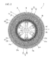
Fig. 2 is a side view of the non-pneumatic tire shown inFig. 1 when seen from one side in a tire width direction. -
Fig. 3 is a plan view of a first split case body of the non-pneumatic tire shown inFig. 1 , in which a split ring member of one side and a first elastic connecting plate are integrally formed, when seen from one side in the tire width direction, or a plan view of a second split case body in which a split ring member of the other side and a second elastic connecting plate are integrally formed, when seen from the other side in the tire width direction. -
Fig. 4 is an enlarged view showing a major portion ofFig. 2 . - Hereinafter, an embodiment of a non-pneumatic tire according to the present invention will be described with reference to
Figs. 1 to 4 . - A
non-pneumatic tire 1 includes anattachment body 11 attached to an axle (not shown), aring member 14 including aninner rim 12 fitted onto theattachment body 11 and anouter rim 13 configured to surround theinner rim 12 from the outside in a tire radial direction, a plurality of connectingmembers 15 disposed between theinner rim 12 and theouter rim 13 in a tire circumferential direction and configured to connect therims tread member 16 disposed at an outer circumferential surface side of theouter rim 13 throughout the entire circumference. - Here, the
attachment body 11, theinner rim 12, theouter rim 13, and thetread member 16 are disposed on the same axis as a common axis. Hereinafter, the common axis is referred to as an axis O, a direction along the axis O is referred to as a tire width direction H, a direction perpendicular to the axis O is referred to as a tire radial direction, and a direction around the axis O is referred to as a tire circumferential direction. Further, theattachment body 11, theinner rim 12, theouter rim 13, and thetread member 16 are disposed such that central sections in the tire width direction H coincide with each other. - In the
ring member 14, theouter rim 13 has a larger size in the tire width direction H, i.e., a larger width, than theinner rim 12. In addition, a plurality ofridge sections 12a protruding inward in the tire radial direction and extending throughout the entire length in the tire width direction H are disposed at an inner circumferential surface of theinner rim 12 at intervals in the tire circumferential direction. - As shown in
Figs. 1 and2 , theattachment body 11 includes a mountingcylindrical section 17 on which a front end section of the axle is mounted, anouter ring section 18 configured to surround the mountingcylindrical section 17 from the outside in the tire radial direction, and a plurality ofribs 19 configured to connect the mountingcylindrical section 17 and theouter ring section 18. - The mounting
cylindrical section 17, theouter ring section 18, and theribs 19 are integrally formed of a metal material such as an aluminum alloy or the like. The mountingcylindrical section 17 and theouter ring section 18 are formed in a cylindrical shape and disposed on the same axis as the axis O. The plurality ofribs 19 are disposed at equal intervals in the circumferential direction. - A plurality of
key groove sections 18a concaved inward in the tire radial direction and extending in the tire width direction H are formed at an outer circumferential surface of theouter ring section 18 at intervals in the tire circumferential direction. In the outer circumferential surface of theouter ring section 18, thekey groove sections 18a are opened at only one side of both ends in the tire width direction H and closed at the other side. Theridge sections 12a of theinner rim 12 in thering member 14 are fitted into thekey groove sections 18a. - Further, in wall surfaces configured to form the
key groove sections 18a, a pair of side wall surfaces opposite to each other in the tire circumferential direction are perpendicular to a bottom wall surface. In addition, in outer surfaces of theridge sections 12a, the pair of side wall surfaces standing upward from the inner circumferential surface of theinner rim 12 are perpendicular to a top wall surface directed inward in the tire radial direction. Sizes in the tire circumferential direction of theridge sections 12a and thekey groove sections 18a are equal to each other. - Here, in an edge of one side in the tire width direction H of the
outer ring section 18,concave sections 18b concaved toward the other side in the tire width direction H and into whichplate members 28 are fitted are formed at positions corresponding to thekey groove sections 18a. Through-holes are formed in theplate members 28, and in the wall surfaces that form theconcave sections 18b, female screw sections in communication with the through-holes of theplate members 28 fitted into theconcave sections 18b are formed in the wall surface facing the one side in the tire width direction H. Further, the plurality of female screw sections and the plurality of through-holes are formed at intervals in the tire circumferential direction. - Then, the
ring member 14 is fixed to theattachment body 11 by bolts threaded into the female screw sections through the through-holes of theplate members 28 fitted into theconcave sections 18b in a state in which theinner rim 12 is fitted onto theattachment body 11 from the outside and theridge sections 12a are fitted into thekey groove sections 18a. In this state, theridge sections 12a are sandwiched between theplate members 28 and the other end wall surfaces of the wall surfaces forming theconcave sections 18b disposed at the other end in the tire width direction H and facing the one side in the tire width direction H. - Further, a plurality of
hole arrays 18c, in each of which a plurality of weight-reducing holes passing in the tire radial direction are disposed at intervals in the tire width direction H, are formed at a portion of theouter ring section 18 disposed between thekey groove sections 18a neighboring in the tire circumferential direction at intervals in the tire circumferential direction. In addition, weight-reducingholes 19a passing in the tire width direction H are also formed in theribs 19. - The
tread member 16 is formed in a cylindrical shape, and integrally covers the outer circumferential surface side of theouter rim 13 of thering member 14 throughout the entire region. Thetread member 16 is formed of, for example, natural rubber and/or vulcanized rubber in which a rubber composition is vulcanized, a thermoplastic material, or the like. For example, a thermoplastic elastomer, a thermoplastic resin, or the like is provided as the thermoplastic material. For example, an amide-based thermoplastic elastomer (TPA), an ester-based thermoplastic elastomer (TPC), an olefin-based thermoplastic elastomer (TPO), a styrene-based thermoplastic elastomer (TPS), a urethane-based thermoplastic elastomer (TPU), a thermoplastic rubber cross-linked body (TPV), or another thermoplastic elastomer (TPZ) or the like, defined by Japanese Industrial Standards JIS K6418, is provided as the thermoplastic elastomer. For example, a urethane resin, an olefin resin, a polyvinyl chloride resin, a polyamide resin, or the like, is provided as the thermoplastic resin. Further, in view of an abrasion resistance property, thetread member 16 may be formed of the vulcanized rubber. - The connecting
members 15 include first elastic connectingplates 21 and second elastic connectingplates 22 configured to connect theinner rim 12 and theouter rim 13 of thering member 14. - The plurality of (in the example shown, 60) connecting
members 15 are installed in the tire circumferential direction such that the plurality of first elastic connectingplates 21 are disposed in the tire circumferential direction at one predetermined positions in the tire width direction H, and the plurality of second elastic connectingplates 22 are disposed in the tire circumferential direction at other positions in the tire width direction H different from the one predetermined positions in the tire width direction H. - That is, the plurality of first elastic connecting
plates 21 are disposed in the tire circumferential direction at the same positions as in the tire width direction H, and the plurality of second elastic connectingplates 22 are disposed in the tire circumferential direction at predetermined positions in the same tire width direction H spaced apart from the first elastic connectingplates 21 in the tire width direction H. - Further, the plurality of connecting
members 15 are disposed at positions rotationally symmetrical with respect to the axis O between theinner rim 12 and theouter rim 13 of thering member 14. In addition, all of the connectingmembers 15 have the same shape and the same size. Further, widths of the connectingmembers 15 are smaller than a width of theouter rim 13. - Then, the first elastic connecting
plates 21 neighboring in the tire circumferential direction do not come in contact with each other, and the second elastic connectingplates 22 neighboring in the tire circumferential direction do not come in contact with each other either. Further, the first elastic connectingplates 21 and the second elastic connectingplates 22 neighboring in the tire width direction H do not come in contact with each other either. - Further, the first elastic connecting
plates 21 and the second elastic connectingplates 22 have the same widths. In addition, the first elastic connectingplates 21 and the second elastic connectingplates 22 also have the same thicknesses. - Here, in the first elastic connecting
plates 21, oneend sections 21 a connected to theouter rim 13 are disposed closer to one side in the tire circumferential direction thanother end sections 21b connected to theinner rim 12, and in the second elastic connectingplates 22, oneend sections 22a connected to theouter rim 13 are disposed closer to the other side in the tire circumferential direction than theother end sections 22b connected to theinner rim 12. - In addition, the one
end sections plates 21 and the second elastic connectingplates 22 of the one connectingmembers 15 are disposed at different positions in the tire width direction H and connected at the same positions in the tire circumferential direction in the inner circumferential surface of theouter rim 13. - In the example shown, in the first elastic connecting
plates 21 and the second elastic connectingplates 22, a plurality ofcurved sections 21d to 21f and 22d to 22f curved in the tire circumferential direction are formed atintermediate portions end sections other end sections plates tire 1 is seen from the tire width direction H in a side view of the tire. In the plurality ofcurved sections 21d to 21f and 22d to 22f of all of the connectingplates curved sections 21d to 21f and 22d to 22f neighboring in the above-mentioned extending direction are opposite to each other. - The plurality of
curved sections 21d to 21f formed at the first elastic connectingplates 21 have the firstcurved sections 21 d curved to protrude toward the other side in the tire circumferential direction, the secondcurved sections 21e disposed between the firstcurved sections 21d and the oneend sections 21a and curved to protrude toward the one side in the tire circumferential direction, and the thirdcurved sections 21f disposed between the firstcurved sections 21 d and theother end sections 21 b and curved to protrude toward the one side in the tire circumferential direction. - The plurality of
curved sections 22d to 22f formed at the second elastic connectingplates 22 have the firstcurved sections 22d curved to protrude toward the one side in the tire circumferential direction, the secondcurved sections 22e disposed between the firstcurved sections 22d and the oneend sections 22a and curved to protrude toward the other side in the tire circumferential direction, and the thirdcurved sections 22f disposed between the firstcurved sections 22d and theother end sections 22b and curved to protrude toward the other side in the tire circumferential direction. - In the example shown, the first
curved sections curved sections curved sections curved sections plates 21 and the second elastic connectingplates 22. - Further, the lengths of all of the elastic connecting
plates Fig. 4 , theother end sections plates inner rim 12 opposite to the oneend sections curved sections curved sections curved sections plates 21 and the second elastic connectingplates 22 protrude to oppose each other in the tire circumferential direction and have the same sizes. - Accordingly, as shown in
Fig. 4 , shapes of the connectingmembers 15 when seen in the side view of the tire extend in the tire radial direction, and are linearly symmetrical with respect to an imaginary line L passing through the oneend sections plates - In addition, in all of the elastic connecting
plates end sections other end sections plates members 15 and securing flexibility of the connectingmembers 15. Further, the one end side portions smoothly continue to the other end side portions with no step difference. - Then, in the embodiment, the
ring member 14 and the plurality of connectingmembers 15 are integrally formed of a synthetic resin material. A bending modulus of elasticity of the synthetic resin material obtained through a 3-point bending test pursuant to ISO 178 is 300 MPa or more, and a melting point is 120 °C or more and 350 °C or less. In addition, the bending modulus of elasticity of the synthetic resin material is 12000 MPa or less, or preferably 4500 MPa or less. Further, the synthetic resin material may be only one kind of resin material, a mixture including two or more kinds of resin materials, or a mixture including one or more kinds of resin material and one or more kinds of elastomers, and further, for example, may include additives such as an antioxidant, a plasticizer, a filler, a fiber, a pigment, or the like. When the two or more kinds of resin materials are included, it is referred to as a melting point of a sea phase of a sea-island structure. In addition, the "melting point" disclosed herein represents a specific temperature at which melting starts measured by a differential scanning calorimeter (DSC) of a micro melting point measurement method or the like. - Further, in the embodiment, as shown in
Fig. 1 , thering member 14 is divided into onesplit ring member 23 disposed at one side in the tire width direction H and the othersplit ring member 24 disposed at the other side in the tire width direction H. Further, in the shown example, thering member 14 is divided at a central section in the tire width direction - Then, the one
split ring member 23 is integrally formed with the first elastic connectingplates 21, and the othersplit ring member 24 is integrally formed with the second elastic connectingplates 22. - Further, in the embodiment, the one
split ring member 23 and the first elastic connectingplates 21, and the othersplit ring member 24 and the second elastic connectingplates 22 are integrally formed through injection molding. - Hereinafter, a member obtained by integrally forming the one
split ring member 23 and the first elastic connectingplates 21 is referred to as a firstsplit case body 31, and a member obtained by integrally forming the othersplit ring member 24 and the second elastic connectingplates 22 is referred to as a secondsplit case body 32. - Here, the injection molding may be a general method of simultaneously forming both of the entire first and second
split case bodies split case bodies split ring members plates - In addition, in the first and second
split case bodies split ring members plates - Further, when both of the entire first and second
split case bodies ridge sections 12a formed at theinner rim 12 may be a gate portion. - In the first and second
split case bodies plates outer rim 13, and a central section in the tire width direction H of theinner rim 12 coincide with each other, and theinner rim 12 has a smaller width than theouter rim 13, and has the same width as the first elastic connectingplates 21 and the second elastic connectingplates 22. - Then, edges in the tire width direction H of the
outer rim 13 of the onesplit ring member 23 and theouter rim 13 of the othersplit ring member 24 are connected by, for example, welding, fusion, adhesion, or the like. Further, among these, in the case of the welding, for example, hot plate welding or the like may be employed. Here, since the melting point of the synthetic resin material is 350 °C or less, when the onesplit ring member 23 and the othersplit ring member 24 are connected through welding or fusion, thesplit ring members split ring members - In addition, edges in the tire width direction H of the
inner rim 12 of the onesplit ring member 23 and theinner rim 12 of the othersplit ring member 24 are separated from each other in the tire width direction H. Accordingly, generation of burrs on the inner circumferential surface of theinner rim 12 fitted onto theattachment body 11 from the outside is prevented. - In addition, the first
split case body 31 and the secondsplit case body 32 have the same shape and the same size as shown inFig. 3 in a state before thebodies - Then, when connected as described above, the
non-pneumatic tire 1 is obtained as the edges in the tire width direction H of theouter rims 13 of the firstsplit case body 31 and the secondsplit case body 32 match to be connected to each other in a state in which directions in the tire width direction H of both of thesplit case bodies split case body 31 and the secondsplit case body 32, such that the connectingmembers 15 are line-symmetrical to each other as described above when seen in the side view of the tire. - As described above, since the
non-pneumatic tire 1 according to the embodiment includes the firstsplit case body 31 in which the onesplit ring member 23 and the first elastic connectingplates 21 are integrally formed, and the secondsplit case body 32 in which the othersplit ring member 24 and the second elastic connectingplates 22 are integrally formed, when thenon-pneumatic tire 1 is assembled, even if not all of theend sections members 15 are connected to theinner rim 12 and theouter rim 13, since it is enough of the first and secondsplit case bodies attachment body 11, manufacturing time can be reduced. - In addition, since the first and second
split case bodies end sections member 15 are connected to theinner rim 12 and theouter rim 13 using a fastening member or the like. - In particular, since the bending modulus of elasticity of the synthetic resin material that integrally forms the
ring member 14 and the plurality of connectingmembers 15 is set within a predetermined range, strength necessary and sufficient for thenon-pneumatic tire 1 can be reliably provided. - In addition, when the bending modulus of elasticity of the synthetic resin material is 12000 MPa or less, good ride comfort characteristics can be provided.
- Moreover, since the melting point of the synthetic resin material is 120 °C or more, upon travel of the vehicle on which the
non-pneumatic tire 1 is mounted, even when thenon-pneumatic tire 1 is repeatedly elastically deformed to generate heat, unrecoverable deformation can be prevented, and since the melting point is 350 °C or less, thering member 14 and the plurality of connectingmembers 15 can be easily integrally formed. - Further, since the plurality of first elastic connecting
plates 21 are disposed in the tire circumferential direction at one positions in the tire width direction H and the plurality of second elastic connectingplates 22 are disposed in the tire circumferential direction at other positions in the tire width direction H, interference between the connectingmembers 15 neighboring in the tire circumferential direction can be suppressed, and restriction on the number disposed can be suppressed. - In addition, the one
end sections 21a of the first elastic connectingplates 21 connected to theouter rim 13 are disposed closer to one side in the tire circumferential direction than theother end sections 21b connected to theinner rim 12, and the oneend sections 22a of the second elastic connectingplates 22 connected to theouter rim 13 are disposed closer to the other side in the tire circumferential direction than theother end sections 22b connected to theinner rim 12. For this reason, when an external force is applied to thenon-pneumatic tire 1, the first elastic connectingplate 21 and the second elastic connectingplate 22 can be easily elastically deformed. Accordingly, flexibility can be provided to thenon-pneumatic tire 1 to secure good ride comfort characteristics. - Further, in the first
split case body 31 and the secondsplit case body 32, either the plurality of first elastic connectingplates 21 or the plurality of second elastic connectingplates 22 which extend in a certain direction are disposed in plural between theouter rim 13 and theinner rim 12 when seen in the side view of the tire, and the others which extend in another direction are not disposed therebetween. For this reason, when thering member 14 and the connectingmembers 15 are formed, first, by forming the first and secondsplit case bodies ring member 14 and the connectingmembers 15 can be integrally formed. Accordingly, in comparison with the case in which the case body having a complex structure is formed, thenon-pneumatic tire 1 can be easily and reliably formed. - In addition, as described above, since the melting point of the synthetic resin material is 350 °C or less, when the first
split case body 31 and the secondsplit case body 32 are connected through, for example, welding or fusion, even if a temperature of heating thesplit case bodies split case bodies - In addition, since the first and second
split case bodies non-pneumatic tire 1 can be more easily formed. - However, as described above, in the
split case bodies plates outer rim 13 and theinner rim 12. Accordingly, when thesplit case bodies non-pneumatic tire 1 can be more easily and reliably formed. - In addition, since the connecting
members 15 are line-symmetrically formed with respect to the imaginary line L when seen in the side view of the tire, occurrence of a difference between a spring constant along one side in the tire circumferential direction of thenon-pneumatic tire 1 and a spring constant along the other side can be suppressed, and good controllability can be provided. - Further, the technical spirit of the present invention is not limited to the embodiment but various modifications may be made without departing from the spirit of the present invention.
- For example, curve directions of the
curved sections 21d to 21f in the first elastic connectingplates 21 and curve directions of thecurved sections 22d to 22f in the second elastic connectingplates 22 are not limited to the embodiment but may be appropriately varied. - In addition, in the embodiment, a configuration in which one of the first elastic connecting
plates 21 and the second elastic connectingplates 22 are provided as the connectingmembers 15 is shown. However, instead of this, a configuration in which both a plurality of the first elastic connectingplates 21 and a plurality of the second elastic connectingplates 22 are provided as one of the connectingmembers 15 at different positions in the tire width direction H may be employed. - In addition, the plurality of connecting
members 15 may be disposed in the tire width direction H between theinner rim 12 and theouter rim 13. - In addition, unlike the embodiment, for example, the
other end sections plates 21 and the second elastic connectingplates 22 may be connected at opposite positions of the outer circumferential surface of theinner rim 12 with the axis O interposed therebetween in the tire radial direction. Alternatively, in the outer circumferential surface of theinner rim 12, they may be connected to the oneend sections plate 21 and the second elastic connectingplate 22 at opposite positions or the like in the tire radial direction. - In addition, unlike the embodiment, the one
end sections plates outer rim 13 at different positions in the tire circumferential direction. - Further, a gap in the tire width direction H may not be provided between the
inner rim 12 of the onesplit ring member 23 and theinner rim 12 of the othersplit ring member 24. - In addition, the
ring member 14 may be divided into three portions or more in the tire width direction H, or may not be divided. - Further, only the
inner rim 12 of thering member 14 and the connectingmembers 15 may be integrally formed of the synthetic resin material, or only theouter rim 13 of thering member 14 and the connectingmembers 15 may be integrally formed of the synthetic resin material. - Moreover, the components of the above-mentioned embodiment may be appropriately substituted with known components or the above-mentioned variants may be appropriately combined without departing from the spirit of the present invention.
- A verification test with respect to the above-mentioned effects was performed.
- As an example and shown in Table 1, seven kinds of non-pneumatic tires in which the
ring member 14 and the plurality of connectingmembers 15 were integrally formed of the synthetic resin material having the bending modulus of elasticity of 300 MPa or more and the melting point of 120 °C or more and 350 °C or less were formed. As comparative examples, as shown in Table 2, three kinds of non-pneumatic tires in which the ring member and the plurality of connecting members were integrally formed of the synthetic resin material having the bending modulus of elasticity of less than 300 MPa and the melting point of more than 350 °C were formed. - Here, with respect to all ten kinds of non-pneumatic tires, it was checked whether the tires broke when a compressive force of 3000 kN was applied in the tire radial direction or whether the tires broke when the tires were compressively deformed by 20 mm in the tire radial direction (load resistant test).
- As a result, it was confirmed that none of the non-pneumatic tires of the examples broke, and among the non-pneumatic tires of the comparative examples, the tires in Comparative Examples 1 and 2 having the bending modulus of elasticity of less than 300 MPa broke.
- In addition, in all ten kinds of non-pneumatic tires, in the case in which the first split case body and the second split case body were welded through hot plate welding, when the tires were heated at a temperature of 0 °C or more and 50 °C or less with respect to the melting point of the synthetic resin material, it was verified whether the split case bodies were connected well.
- As a result, in all of the non-pneumatic tires of the examples, it was confirmed that the split case bodies were connected well, and among the non-pneumatic tires of the comparative examples, in Comparative Example 3 in which the melting point of the synthetic resin material exceeded 350 °C, it was confirmed that the split case bodies were not connected well.
- In addition, as a result of a travel test of Comparative Example 4, a load support section was softened and it could no longer be used as a tire.
[Table 1] Examples 1 2 3 4 5 6 7 8 Kind of resin N12 N66 N6 PBT PPS TPAE PPS PPS/ Elastomer Maker Ube Industries Unitika Ltd. Ube Industries WinTech Polymer Ltd. Polyplastic Inc. Ube Industries Toray Industries DIC Corp. Grade 3024U A125J 1013B 2002 0220A9 XPA9055 A673M Z200-E5 Bending modulus of elasticity (MPa) 1000 1100 750 2630 3800 300 10000 3200 Melting point (°C) 176 262 222 224 290 162 278 280 Load resistant test ○ ○ ○ ○ ○ ○ ○ ○ Welding test ○ ○ ○ ○ ○ ○ ○ ○ [Table 2] Comparative example 1 2 3 4 Kind of resin TPO TPAE PEEK LDPE Maker Prime Polymer Co., Ltd. Ube Industries Victrex plc. Asahi Kasei Chemicals Inc. Grade F-3740 XPA9048 ST45GL30 M6545 Bending modulus of elasticity (MPa) 240 180 12000 100 Melting point (°C) 141 154 387 110 Load resistant test × × ○ × Welding test ○ ○ × ○ - A non-pneumatic tire can be easily assembled, and an increase in weight can be suppressed.
-
- 1
- non-pneumatic tire
- 11
- attachment body
- 12
- inner rim
- 13
- outer rim
- 14
- ring member
- 15
- connecting member
- 21
- first elastic connecting plate
- 22
- second elastic connecting plate
- 21a, 22a
- one end section
- 21b, 22b
- other end section
- 23
- one split ring member
- 24
- other split ring member
- H
- tire width direction
- L
- imaginary line
- O
- axis
Claims (7)
- A non-pneumatic tire comprising:an attachment body attached to an axle;a ring member including an inner rim fitted onto the attachment body and an outer rim configured to surround the inner rim from the outside in a tire radial direction; anda plurality of connecting members disposed between the inner rim and the outer rim in a tire circumferential direction and configured to connect the rims to each other,wherein at least a portion of the ring member and the plurality of connecting members are integrally formed of a synthetic resin material having a bending modulus of elasticity obtained through a 3-point bending test pursuant to ISO 178 of 300 MPa or more and a melting point of 120 °C or more and 350 °C or less.
- The non-pneumatic tire according to claim 1, wherein the connecting members comprise first elastic connecting plates and second elastic connecting plates configured to connect the rims to each other,
one end sections of the first elastic connecting plates connected to the outer rim are disposed closer to one side in the tire circumferential direction than the other end sections connected to the inner rim,
one end sections of the second elastic connecting plates connected to the outer rim are disposed closer to the other side in the tire circumferential direction than the other end sections connected to the inner rim, and
the plurality of first elastic connecting plates are disposed in the tire circumferential direction at one positions in the tire width direction, and the plurality of second elastic connecting plates are disposed in the tire circumferential direction at other positions in the tire width direction different from the one positions in the tire width direction. - The non-pneumatic tire according to claim 2, wherein the ring member is divided into one split ring member disposed at one side in the tire width direction and the other split ring member disposed at the other side in the tire width direction,
the one split ring member is integrally formed with the first elastic connecting plates, and
the other split ring member is integrally formed with the second elastic connecting plates. - The non-pneumatic tire according to claim 3, wherein the one split ring member and the first elastic connecting plates, and the other split ring member and the second elastic connecting plates are integrally formed through injection molding.
- The non-pneumatic tire according to claim 2, wherein one end sections of a first elastic connecting plate and a second elastic connecting plate of one of the connecting members are disposed at different positions in the tire width direction and connected at the same position in the tire circumferential direction in an inner circumferential surface of the outer rim, and
the connecting member extends in the tire radial direction when the tire is seen in a side view of the tire from the tire width direction, and is line-symmetrically formed with respect to an imaginary line passing through the one end sections. - The non-pneumatic tire according to claim 3, wherein one end sections of a first elastic connecting plate and a second elastic connecting plate of one of the connecting members are disposed at different positions in the tire width direction and connected at the same position in the tire circumferential direction in an inner circumferential surface of the outer rim, and
the connecting member extends in the tire radial direction when the tire is seen in a side view of the tire from the tire width direction, and is line-symmetrically formed with respect to an imaginary line passing through the one end sections. - The non-pneumatic tire according to claim 4, wherein one end sections of a first elastic connecting plate and a second elastic connecting plate of one of the connecting members are disposed at different positions in the tire width direction and connected at the same position in the tire circumferential direction in an inner circumferential surface of the outer rim, and
the connecting member extends in the tire radial direction when the tire is seen in a side view of the tire from the tire width direction, and is line-symmetrically formed with respect to an imaginary line passing through the one end sections.
Applications Claiming Priority (2)
| Application Number | Priority Date | Filing Date | Title |
|---|---|---|---|
| JP2012282665 | 2012-12-26 | ||
| PCT/JP2013/083202 WO2014103721A1 (en) | 2012-12-26 | 2013-12-11 | Non-pneumatic tyre |
Publications (3)
| Publication Number | Publication Date |
|---|---|
| EP2939850A1 true EP2939850A1 (en) | 2015-11-04 |
| EP2939850A4 EP2939850A4 (en) | 2016-08-31 |
| EP2939850B1 EP2939850B1 (en) | 2019-10-23 |
Family
ID=51020810
Family Applications (1)
| Application Number | Title | Priority Date | Filing Date |
|---|---|---|---|
| EP13868430.3A Not-in-force EP2939850B1 (en) | 2012-12-26 | 2013-12-11 | Non-pneumatic tyre |
Country Status (5)
| Country | Link |
|---|---|
| US (1) | US9511631B2 (en) |
| EP (1) | EP2939850B1 (en) |
| JP (1) | JP6242015B2 (en) |
| CN (1) | CN104797435B (en) |
| WO (1) | WO2014103721A1 (en) |
Cited By (1)
| Publication number | Priority date | Publication date | Assignee | Title |
|---|---|---|---|---|
| RU2756985C1 (en) * | 2021-02-26 | 2021-10-08 | Иван Сергеевич Русанов | Pneumatic tire |
Families Citing this family (18)
| Publication number | Priority date | Publication date | Assignee | Title |
|---|---|---|---|---|
| JP5879089B2 (en) * | 2011-10-20 | 2016-03-08 | 株式会社ブリヂストン | Non-pneumatic tire manufacturing method |
| JP6242015B2 (en) * | 2012-12-26 | 2017-12-06 | 株式会社ブリヂストン | Non pneumatic tire |
| JP6051037B2 (en) * | 2012-12-26 | 2016-12-21 | 株式会社ブリヂストン | Non pneumatic tire |
| EP3007909A4 (en) | 2013-06-15 | 2017-03-01 | Ronald Thompson | Annular ring and non-pneumatic tire |
| CN106457886B (en) * | 2014-06-24 | 2019-04-23 | 株式会社普利司通 | Non-pneumatic tires |
| EP3253591B1 (en) | 2015-02-04 | 2021-06-30 | Camso Inc. | Non-pneumatic tire and other annular devices |
| CN106183637B (en) * | 2015-04-29 | 2018-10-26 | 汪烈生 | The connection method of embedded decline air bag array safety tread and wheel hub |
| CN104972838B (en) * | 2015-07-03 | 2019-01-29 | 深圳市道尔轮胎科技有限公司 | A Tubular Inline Open Structure Tire Without Tyre Burst |
| US11999419B2 (en) | 2015-12-16 | 2024-06-04 | Camso Inc. | Track system for traction of a vehicle |
| KR101789407B1 (en) * | 2016-02-26 | 2017-10-23 | 엘지전자 주식회사 | Robot cleaner and wheel assembly |
| CN106394127B (en) * | 2016-12-06 | 2017-12-22 | 安徽江淮汽车集团股份有限公司 | Air-free tyre and automobile |
| CN106379113B (en) * | 2016-12-06 | 2017-11-10 | 安徽江淮汽车集团股份有限公司 | Air-free tyre and automobile |
| EP3638515B1 (en) | 2017-06-15 | 2023-04-05 | Camso Inc. | Wheel comprising a non-pneumatic tire |
| WO2019093212A1 (en) * | 2017-11-10 | 2019-05-16 | 株式会社ブリヂストン | Nonpneumatic tire |
| WO2019118225A1 (en) | 2017-12-14 | 2019-06-20 | Bridgestone Americas Tire Operations, Llc | Non-pneumatic tire with multi-piece web |
| WO2020023235A1 (en) | 2018-07-27 | 2020-01-30 | Bridgestone Americas Tire Operations, Llc | Reusable rim for non-pneumatic tires |
| CN113195255B (en) | 2018-11-14 | 2024-01-19 | 普利司通美国轮胎运营有限责任公司 | Tire rim assembly having inner rim component and outer rim component |
| JP7466285B2 (en) | 2019-10-21 | 2024-04-12 | 株式会社ブリヂストン | Wheel |
Family Cites Families (61)
| Publication number | Priority date | Publication date | Assignee | Title |
|---|---|---|---|---|
| US1027983A (en) * | 1910-05-16 | 1912-05-28 | John A Mangan | Tire. |
| US1450748A (en) * | 1919-09-05 | 1923-04-03 | James A Morrow | Spring wheel |
| US1391740A (en) * | 1921-03-31 | 1921-09-27 | Kostecki Michael | Spring-wheel |
| US1636310A (en) * | 1921-08-30 | 1927-07-19 | David H Ludlow | Wheel |
| US2620844A (en) * | 1950-04-27 | 1952-12-09 | Lord Mfg Co | Cushioned tire |
| US3730244A (en) * | 1968-04-17 | 1973-05-01 | Grace W R & Co | Compressible vehicle tire |
| US4071279A (en) * | 1975-04-21 | 1978-01-31 | The Goodyear Tire & Rubber Company | Solid polyurethane tire and wheel assembly |
| US4287927A (en) * | 1978-06-30 | 1981-09-08 | The Goodyear Tire & Rubber Company | Multiple ring tire |
| US4235270A (en) * | 1978-06-30 | 1980-11-25 | The Goodyear Tire & Rubber Company | Tire with supporting and cushioning walls |
| DE3175652D1 (en) * | 1980-11-10 | 1987-01-15 | Wheel Dev Ltd | Wheel with resilient spokes |
| US4921029A (en) * | 1984-04-16 | 1990-05-01 | The Uniroyal Goodrich Tire Company | Trapezoidal non-pneumatic tire with supporting and cushioning members |
| CA1239854A (en) | 1984-04-16 | 1988-08-02 | Uniroyal, Inc. | Non-pneumatic tire with supporting and cushioning members |
| US4832098A (en) * | 1984-04-16 | 1989-05-23 | The Uniroyal Goodrich Tire Company | Non-pneumatic tire with supporting and cushioning members |
| AT394827B (en) | 1985-10-16 | 1992-06-25 | Uniroyal Goodrich Tire Co | Tyre |
| GB8608270D0 (en) * | 1986-04-04 | 1986-05-08 | Jones S | Ground-engaging wheels for vehicles |
| US4784201A (en) * | 1986-05-13 | 1988-11-15 | The Uniroyal Goodrich Tire Company | Non-pneumatic tire with vibration reducing features |
| JPH0195905A (en) * | 1987-10-08 | 1989-04-14 | Sumitomo Rubber Ind Ltd | Casting tire |
| US4934425A (en) * | 1988-03-23 | 1990-06-19 | Uniroyal Chemical Company, Inc. | Non-pneumatic tire |
| JPH02182501A (en) * | 1988-07-27 | 1990-07-17 | Sumitomo Rubber Ind Ltd | Non-pneumatic tire |
| US4945962A (en) * | 1989-06-09 | 1990-08-07 | The Uniroyal Goodrich Tire Company | Honeycomb non-pneumatic tire with a single web on one side |
| FR2652310A1 (en) * | 1989-09-28 | 1991-03-29 | Michelin & Cie | NON-PNEUMATIC DEFORMABLE BANDAGE. |
| CA2043082A1 (en) * | 1991-02-27 | 1992-08-28 | James Edward Duddey | Non-pneumatic spare tire |
| US5174634A (en) * | 1991-06-28 | 1992-12-29 | Motor Wheel Corporation | Non-pneumatic spare wheel and tire |
| US5223599A (en) * | 1992-04-10 | 1993-06-29 | Uniroyal Chemical Company, Inc. | Polyurethane elastomer and non-pneumatic tire fabricated therefrom |
| US7418988B2 (en) * | 1999-12-10 | 2008-09-02 | Michelin Recherche Et Technique S.A. | Non-pneumatic tire |
| US6615885B1 (en) * | 2000-10-31 | 2003-09-09 | Irobot Corporation | Resilient wheel structure |
| US7174936B2 (en) * | 2003-12-22 | 2007-02-13 | Caterpillar Inc | Solid suspended work machine tire |
| US8091596B2 (en) * | 2005-04-29 | 2012-01-10 | Big Tyre Pty Ltd | Non-pneumatic tyre assembly |
| US7523773B2 (en) * | 2005-10-21 | 2009-04-28 | The Boeing Company | Non-pneumatic wheel |
| JP3966895B1 (en) | 2006-08-29 | 2007-08-29 | 横浜ゴム株式会社 | Non-pneumatic tire |
| US8109308B2 (en) * | 2007-03-27 | 2012-02-07 | Resilient Technologies LLC. | Tension-based non-pneumatic tire |
| US8104524B2 (en) * | 2007-03-27 | 2012-01-31 | Resilient Technologies Llc | Tension-based non-pneumatic tire |
| WO2009016962A1 (en) * | 2007-07-31 | 2009-02-05 | Toyo Tire & Rubber Co., Ltd. | Non-pneumatic tire, and its manufacturing method |
| FR2921013B1 (en) * | 2007-09-14 | 2009-11-27 | Soc Tech Michelin | NON-PNEUMATIC ELASTIC WHEEL. |
| JP4506853B2 (en) | 2008-02-25 | 2010-07-21 | 横浜ゴム株式会社 | Non-pneumatic tire |
| JP2009286208A (en) | 2008-05-28 | 2009-12-10 | Yokohama Rubber Co Ltd:The | Non-pneumatic tire |
| JP5436018B2 (en) * | 2008-07-09 | 2014-03-05 | 株式会社ブリヂストン | Non pneumatic tire |
| JP4674253B2 (en) * | 2008-11-28 | 2011-04-20 | 東洋ゴム工業株式会社 | Non-pneumatic tire |
| JP5221306B2 (en) * | 2008-11-28 | 2013-06-26 | 東洋ゴム工業株式会社 | Non-pneumatic tire |
| US8176957B2 (en) * | 2009-07-20 | 2012-05-15 | Resilient Technologies, Llc. | Tension-based non-pneumatic tire |
| US8944125B2 (en) * | 2009-07-20 | 2015-02-03 | Polaris Industries Inc. | Tension-based non-pneumatic tire |
| JP5622400B2 (en) | 2010-01-29 | 2014-11-12 | 株式会社ブリヂストン | Non pneumatic tire |
| US8688421B2 (en) * | 2010-03-31 | 2014-04-01 | Compagnie Generale Des Etablissements Michelin | Method to design honeycombs for a shear flexible structure |
| US8555941B2 (en) * | 2010-08-12 | 2013-10-15 | The Boeing Company | Non-pneumatic survivable tire, cover and fabrication processes |
| US9254716B2 (en) * | 2010-09-01 | 2016-02-09 | Compagnie Generale Des Etablissements Michelin | Spoke edge geometry for a non-pneumatic tire |
| KR101043001B1 (en) * | 2010-09-14 | 2011-06-21 | 한국타이어 주식회사 | Airless tire |
| JP5879089B2 (en) * | 2011-10-20 | 2016-03-08 | 株式会社ブリヂストン | Non-pneumatic tire manufacturing method |
| WO2013152067A1 (en) * | 2012-04-05 | 2013-10-10 | Compagnie Generale Des Establissements Michelin | Spoke for a tire with optimized thickness for improved durability |
| JP6027392B2 (en) * | 2012-10-19 | 2016-11-16 | 株式会社ブリヂストン | Non pneumatic tire |
| JP5930941B2 (en) * | 2012-10-31 | 2016-06-08 | 株式会社ブリヂストン | Non pneumatic tire |
| US9149994B2 (en) * | 2012-12-12 | 2015-10-06 | Caterpillar Inc. | Systems for molding non-pneumatic tires |
| WO2014103680A1 (en) * | 2012-12-26 | 2014-07-03 | 株式会社ブリヂストン | Non-pneumatic tyre |
| JP6051037B2 (en) * | 2012-12-26 | 2016-12-21 | 株式会社ブリヂストン | Non pneumatic tire |
| JP6242015B2 (en) * | 2012-12-26 | 2017-12-06 | 株式会社ブリヂストン | Non pneumatic tire |
| USD731962S1 (en) * | 2013-03-15 | 2015-06-16 | Caterpillar Inc. | Surface pattern for a tire |
| USD727247S1 (en) * | 2013-03-15 | 2015-04-21 | Caterpillar Inc. | Non-pneumatic tire |
| JP6291489B2 (en) * | 2013-05-22 | 2018-03-14 | 住友ゴム工業株式会社 | AIRLESS TIRE AND MANUFACTURING METHOD THEREOF |
| EP3007909A4 (en) * | 2013-06-15 | 2017-03-01 | Ronald Thompson | Annular ring and non-pneumatic tire |
| US20150034222A1 (en) * | 2013-07-30 | 2015-02-05 | Caterpillar Inc. | Tire and system for acquiring data associated with tire |
| KR101411103B1 (en) * | 2013-11-06 | 2014-06-27 | 한국타이어 주식회사 | Non-pneumatic tire |
| KR101623263B1 (en) * | 2014-08-13 | 2016-05-23 | 한국타이어 주식회사 | Non-pneumatic tire improving ride-comfort |
-
2013
- 2013-12-11 JP JP2014554305A patent/JP6242015B2/en not_active Expired - Fee Related
- 2013-12-11 US US14/431,426 patent/US9511631B2/en not_active Expired - Fee Related
- 2013-12-11 WO PCT/JP2013/083202 patent/WO2014103721A1/en not_active Ceased
- 2013-12-11 EP EP13868430.3A patent/EP2939850B1/en not_active Not-in-force
- 2013-12-11 CN CN201380060711.1A patent/CN104797435B/en not_active Expired - Fee Related
Cited By (1)
| Publication number | Priority date | Publication date | Assignee | Title |
|---|---|---|---|---|
| RU2756985C1 (en) * | 2021-02-26 | 2021-10-08 | Иван Сергеевич Русанов | Pneumatic tire |
Also Published As
| Publication number | Publication date |
|---|---|
| JP6242015B2 (en) | 2017-12-06 |
| US20150251492A1 (en) | 2015-09-10 |
| JPWO2014103721A1 (en) | 2017-01-12 |
| EP2939850B1 (en) | 2019-10-23 |
| CN104797435A (en) | 2015-07-22 |
| US9511631B2 (en) | 2016-12-06 |
| CN104797435B (en) | 2018-05-15 |
| WO2014103721A1 (en) | 2014-07-03 |
| EP2939850A4 (en) | 2016-08-31 |
Similar Documents
| Publication | Publication Date | Title |
|---|---|---|
| EP2939850B1 (en) | Non-pneumatic tyre | |
| EP2896510B1 (en) | Non-pneumatic tyre | |
| EP2886368B1 (en) | Non-pneumatic tyre | |
| EP2889158B1 (en) | Non-pneumatic tire | |
| EP2910387B1 (en) | Non-pneumatic tire | |
| US9550393B2 (en) | Non-pneumatic tire | |
| EP2910386B1 (en) | Non-pneumatic tire | |
| US9931890B2 (en) | Non-pneumatic tire | |
| EP2939851B1 (en) | Non-pneumatic tyre | |
| EP3121029B1 (en) | Non-pneumatic tire | |
| US10576786B2 (en) | Non-pneumatic tire | |
| EP3061624B1 (en) | Non-pneumatic tire | |
| US10562352B2 (en) | Non-pneumatic tire | |
| EP3031616A1 (en) | Non-pneumatic tire |
Legal Events
| Date | Code | Title | Description |
|---|---|---|---|
| PUAI | Public reference made under article 153(3) epc to a published international application that has entered the european phase |
Free format text: ORIGINAL CODE: 0009012 |
|
| 17P | Request for examination filed |
Effective date: 20150408 |
|
| AK | Designated contracting states |
Kind code of ref document: A1 Designated state(s): AL AT BE BG CH CY CZ DE DK EE ES FI FR GB GR HR HU IE IS IT LI LT LU LV MC MK MT NL NO PL PT RO RS SE SI SK SM TR |
|
| AX | Request for extension of the european patent |
Extension state: BA ME |
|
| DAX | Request for extension of the european patent (deleted) | ||
| REG | Reference to a national code |
Ref country code: DE Ref legal event code: R079 Ref document number: 602013062119 Country of ref document: DE Free format text: PREVIOUS MAIN CLASS: B60C0007000000 Ipc: B60C0007180000 |
|
| A4 | Supplementary search report drawn up and despatched |
Effective date: 20160728 |
|
| RIC1 | Information provided on ipc code assigned before grant |
Ipc: B60C 7/24 20060101ALI20160722BHEP Ipc: B60C 7/18 20060101AFI20160722BHEP Ipc: B60C 7/12 20060101ALI20160722BHEP Ipc: B60C 7/14 20060101ALI20160722BHEP |
|
| STAA | Information on the status of an ep patent application or granted ep patent |
Free format text: STATUS: EXAMINATION IS IN PROGRESS |
|
| 17Q | First examination report despatched |
Effective date: 20180810 |
|
| GRAP | Despatch of communication of intention to grant a patent |
Free format text: ORIGINAL CODE: EPIDOSNIGR1 |
|
| STAA | Information on the status of an ep patent application or granted ep patent |
Free format text: STATUS: GRANT OF PATENT IS INTENDED |
|
| INTG | Intention to grant announced |
Effective date: 20190115 |
|
| GRAJ | Information related to disapproval of communication of intention to grant by the applicant or resumption of examination proceedings by the epo deleted |
Free format text: ORIGINAL CODE: EPIDOSDIGR1 |
|
| STAA | Information on the status of an ep patent application or granted ep patent |
Free format text: STATUS: EXAMINATION IS IN PROGRESS |
|
| INTC | Intention to grant announced (deleted) | ||
| GRAS | Grant fee paid |
Free format text: ORIGINAL CODE: EPIDOSNIGR3 |
|
| STAA | Information on the status of an ep patent application or granted ep patent |
Free format text: STATUS: GRANT OF PATENT IS INTENDED |
|
| GRAP | Despatch of communication of intention to grant a patent |
Free format text: ORIGINAL CODE: EPIDOSNIGR1 |
|
| INTG | Intention to grant announced |
Effective date: 20190723 |
|
| GRAA | (expected) grant |
Free format text: ORIGINAL CODE: 0009210 |
|
| STAA | Information on the status of an ep patent application or granted ep patent |
Free format text: STATUS: THE PATENT HAS BEEN GRANTED |
|
| AK | Designated contracting states |
Kind code of ref document: B1 Designated state(s): AL AT BE BG CH CY CZ DE DK EE ES FI FR GB GR HR HU IE IS IT LI LT LU LV MC MK MT NL NO PL PT RO RS SE SI SK SM TR |
|
| REG | Reference to a national code |
Ref country code: GB Ref legal event code: FG4D |
|
| REG | Reference to a national code |
Ref country code: CH Ref legal event code: EP |
|
| REG | Reference to a national code |
Ref country code: IE Ref legal event code: FG4D |
|
| REG | Reference to a national code |
Ref country code: DE Ref legal event code: R096 Ref document number: 602013062119 Country of ref document: DE |
|
| REG | Reference to a national code |
Ref country code: AT Ref legal event code: REF Ref document number: 1193247 Country of ref document: AT Kind code of ref document: T Effective date: 20191115 |
|
| REG | Reference to a national code |
Ref country code: NL Ref legal event code: MP Effective date: 20191023 |
|
| REG | Reference to a national code |
Ref country code: LT Ref legal event code: MG4D |
|
| PG25 | Lapsed in a contracting state [announced via postgrant information from national office to epo] |
Ref country code: BG Free format text: LAPSE BECAUSE OF FAILURE TO SUBMIT A TRANSLATION OF THE DESCRIPTION OR TO PAY THE FEE WITHIN THE PRESCRIBED TIME-LIMIT Effective date: 20200123 Ref country code: FI Free format text: LAPSE BECAUSE OF FAILURE TO SUBMIT A TRANSLATION OF THE DESCRIPTION OR TO PAY THE FEE WITHIN THE PRESCRIBED TIME-LIMIT Effective date: 20191023 Ref country code: PT Free format text: LAPSE BECAUSE OF FAILURE TO SUBMIT A TRANSLATION OF THE DESCRIPTION OR TO PAY THE FEE WITHIN THE PRESCRIBED TIME-LIMIT Effective date: 20200224 Ref country code: NL Free format text: LAPSE BECAUSE OF FAILURE TO SUBMIT A TRANSLATION OF THE DESCRIPTION OR TO PAY THE FEE WITHIN THE PRESCRIBED TIME-LIMIT Effective date: 20191023 Ref country code: SE Free format text: LAPSE BECAUSE OF FAILURE TO SUBMIT A TRANSLATION OF THE DESCRIPTION OR TO PAY THE FEE WITHIN THE PRESCRIBED TIME-LIMIT Effective date: 20191023 Ref country code: PL Free format text: LAPSE BECAUSE OF FAILURE TO SUBMIT A TRANSLATION OF THE DESCRIPTION OR TO PAY THE FEE WITHIN THE PRESCRIBED TIME-LIMIT Effective date: 20191023 Ref country code: LV Free format text: LAPSE BECAUSE OF FAILURE TO SUBMIT A TRANSLATION OF THE DESCRIPTION OR TO PAY THE FEE WITHIN THE PRESCRIBED TIME-LIMIT Effective date: 20191023 Ref country code: NO Free format text: LAPSE BECAUSE OF FAILURE TO SUBMIT A TRANSLATION OF THE DESCRIPTION OR TO PAY THE FEE WITHIN THE PRESCRIBED TIME-LIMIT Effective date: 20200123 Ref country code: GR Free format text: LAPSE BECAUSE OF FAILURE TO SUBMIT A TRANSLATION OF THE DESCRIPTION OR TO PAY THE FEE WITHIN THE PRESCRIBED TIME-LIMIT Effective date: 20200124 Ref country code: LT Free format text: LAPSE BECAUSE OF FAILURE TO SUBMIT A TRANSLATION OF THE DESCRIPTION OR TO PAY THE FEE WITHIN THE PRESCRIBED TIME-LIMIT Effective date: 20191023 Ref country code: ES Free format text: LAPSE BECAUSE OF FAILURE TO SUBMIT A TRANSLATION OF THE DESCRIPTION OR TO PAY THE FEE WITHIN THE PRESCRIBED TIME-LIMIT Effective date: 20191023 |
|
| PG25 | Lapsed in a contracting state [announced via postgrant information from national office to epo] |
Ref country code: HR Free format text: LAPSE BECAUSE OF FAILURE TO SUBMIT A TRANSLATION OF THE DESCRIPTION OR TO PAY THE FEE WITHIN THE PRESCRIBED TIME-LIMIT Effective date: 20191023 Ref country code: IS Free format text: LAPSE BECAUSE OF FAILURE TO SUBMIT A TRANSLATION OF THE DESCRIPTION OR TO PAY THE FEE WITHIN THE PRESCRIBED TIME-LIMIT Effective date: 20200224 Ref country code: RS Free format text: LAPSE BECAUSE OF FAILURE TO SUBMIT A TRANSLATION OF THE DESCRIPTION OR TO PAY THE FEE WITHIN THE PRESCRIBED TIME-LIMIT Effective date: 20191023 |
|
| PG25 | Lapsed in a contracting state [announced via postgrant information from national office to epo] |
Ref country code: AL Free format text: LAPSE BECAUSE OF FAILURE TO SUBMIT A TRANSLATION OF THE DESCRIPTION OR TO PAY THE FEE WITHIN THE PRESCRIBED TIME-LIMIT Effective date: 20191023 |
|
| REG | Reference to a national code |
Ref country code: DE Ref legal event code: R097 Ref document number: 602013062119 Country of ref document: DE |
|
| PG2D | Information on lapse in contracting state deleted |
Ref country code: IS |
|
| PG25 | Lapsed in a contracting state [announced via postgrant information from national office to epo] |
Ref country code: EE Free format text: LAPSE BECAUSE OF FAILURE TO SUBMIT A TRANSLATION OF THE DESCRIPTION OR TO PAY THE FEE WITHIN THE PRESCRIBED TIME-LIMIT Effective date: 20191023 Ref country code: DK Free format text: LAPSE BECAUSE OF FAILURE TO SUBMIT A TRANSLATION OF THE DESCRIPTION OR TO PAY THE FEE WITHIN THE PRESCRIBED TIME-LIMIT Effective date: 20191023 Ref country code: CZ Free format text: LAPSE BECAUSE OF FAILURE TO SUBMIT A TRANSLATION OF THE DESCRIPTION OR TO PAY THE FEE WITHIN THE PRESCRIBED TIME-LIMIT Effective date: 20191023 Ref country code: RO Free format text: LAPSE BECAUSE OF FAILURE TO SUBMIT A TRANSLATION OF THE DESCRIPTION OR TO PAY THE FEE WITHIN THE PRESCRIBED TIME-LIMIT Effective date: 20191023 Ref country code: IS Free format text: LAPSE BECAUSE OF FAILURE TO SUBMIT A TRANSLATION OF THE DESCRIPTION OR TO PAY THE FEE WITHIN THE PRESCRIBED TIME-LIMIT Effective date: 20200223 |
|
| REG | Reference to a national code |
Ref country code: CH Ref legal event code: PL |
|
| REG | Reference to a national code |
Ref country code: AT Ref legal event code: MK05 Ref document number: 1193247 Country of ref document: AT Kind code of ref document: T Effective date: 20191023 |
|
| REG | Reference to a national code |
Ref country code: BE Ref legal event code: MM Effective date: 20191231 |
|
| PLBE | No opposition filed within time limit |
Free format text: ORIGINAL CODE: 0009261 |
|
| STAA | Information on the status of an ep patent application or granted ep patent |
Free format text: STATUS: NO OPPOSITION FILED WITHIN TIME LIMIT |
|
| PG25 | Lapsed in a contracting state [announced via postgrant information from national office to epo] |
Ref country code: SM Free format text: LAPSE BECAUSE OF FAILURE TO SUBMIT A TRANSLATION OF THE DESCRIPTION OR TO PAY THE FEE WITHIN THE PRESCRIBED TIME-LIMIT Effective date: 20191023 Ref country code: IT Free format text: LAPSE BECAUSE OF FAILURE TO SUBMIT A TRANSLATION OF THE DESCRIPTION OR TO PAY THE FEE WITHIN THE PRESCRIBED TIME-LIMIT Effective date: 20191023 Ref country code: MC Free format text: LAPSE BECAUSE OF FAILURE TO SUBMIT A TRANSLATION OF THE DESCRIPTION OR TO PAY THE FEE WITHIN THE PRESCRIBED TIME-LIMIT Effective date: 20191023 Ref country code: SK Free format text: LAPSE BECAUSE OF FAILURE TO SUBMIT A TRANSLATION OF THE DESCRIPTION OR TO PAY THE FEE WITHIN THE PRESCRIBED TIME-LIMIT Effective date: 20191023 |
|
| GBPC | Gb: european patent ceased through non-payment of renewal fee |
Effective date: 20200123 |
|
| 26N | No opposition filed |
Effective date: 20200724 |
|
| PG25 | Lapsed in a contracting state [announced via postgrant information from national office to epo] |
Ref country code: LU Free format text: LAPSE BECAUSE OF NON-PAYMENT OF DUE FEES Effective date: 20191211 Ref country code: GB Free format text: LAPSE BECAUSE OF NON-PAYMENT OF DUE FEES Effective date: 20200123 Ref country code: IE Free format text: LAPSE BECAUSE OF NON-PAYMENT OF DUE FEES Effective date: 20191211 |
|
| PG25 | Lapsed in a contracting state [announced via postgrant information from national office to epo] |
Ref country code: BE Free format text: LAPSE BECAUSE OF NON-PAYMENT OF DUE FEES Effective date: 20191231 Ref country code: AT Free format text: LAPSE BECAUSE OF FAILURE TO SUBMIT A TRANSLATION OF THE DESCRIPTION OR TO PAY THE FEE WITHIN THE PRESCRIBED TIME-LIMIT Effective date: 20191023 Ref country code: CH Free format text: LAPSE BECAUSE OF NON-PAYMENT OF DUE FEES Effective date: 20191231 Ref country code: LI Free format text: LAPSE BECAUSE OF NON-PAYMENT OF DUE FEES Effective date: 20191231 Ref country code: SI Free format text: LAPSE BECAUSE OF FAILURE TO SUBMIT A TRANSLATION OF THE DESCRIPTION OR TO PAY THE FEE WITHIN THE PRESCRIBED TIME-LIMIT Effective date: 20191023 |
|
| PGFP | Annual fee paid to national office [announced via postgrant information from national office to epo] |
Ref country code: FR Payment date: 20201223 Year of fee payment: 8 Ref country code: DE Payment date: 20201211 Year of fee payment: 8 |
|
| PG25 | Lapsed in a contracting state [announced via postgrant information from national office to epo] |
Ref country code: CY Free format text: LAPSE BECAUSE OF FAILURE TO SUBMIT A TRANSLATION OF THE DESCRIPTION OR TO PAY THE FEE WITHIN THE PRESCRIBED TIME-LIMIT Effective date: 20191023 |
|
| PG25 | Lapsed in a contracting state [announced via postgrant information from national office to epo] |
Ref country code: HU Free format text: LAPSE BECAUSE OF FAILURE TO SUBMIT A TRANSLATION OF THE DESCRIPTION OR TO PAY THE FEE WITHIN THE PRESCRIBED TIME-LIMIT; INVALID AB INITIO Effective date: 20131211 Ref country code: MT Free format text: LAPSE BECAUSE OF FAILURE TO SUBMIT A TRANSLATION OF THE DESCRIPTION OR TO PAY THE FEE WITHIN THE PRESCRIBED TIME-LIMIT Effective date: 20191023 |
|
| PG25 | Lapsed in a contracting state [announced via postgrant information from national office to epo] |
Ref country code: TR Free format text: LAPSE BECAUSE OF FAILURE TO SUBMIT A TRANSLATION OF THE DESCRIPTION OR TO PAY THE FEE WITHIN THE PRESCRIBED TIME-LIMIT Effective date: 20191023 |
|
| PG25 | Lapsed in a contracting state [announced via postgrant information from national office to epo] |
Ref country code: MK Free format text: LAPSE BECAUSE OF FAILURE TO SUBMIT A TRANSLATION OF THE DESCRIPTION OR TO PAY THE FEE WITHIN THE PRESCRIBED TIME-LIMIT Effective date: 20191023 |
|
| REG | Reference to a national code |
Ref country code: DE Ref legal event code: R119 Ref document number: 602013062119 Country of ref document: DE |
|
| PG25 | Lapsed in a contracting state [announced via postgrant information from national office to epo] |
Ref country code: DE Free format text: LAPSE BECAUSE OF NON-PAYMENT OF DUE FEES Effective date: 20220701 |
|
| PG25 | Lapsed in a contracting state [announced via postgrant information from national office to epo] |
Ref country code: FR Free format text: LAPSE BECAUSE OF NON-PAYMENT OF DUE FEES Effective date: 20211231 |