EP2939848B1 - Quick change system for wheels - Google Patents
Quick change system for wheels Download PDFInfo
- Publication number
- EP2939848B1 EP2939848B1 EP15163904.4A EP15163904A EP2939848B1 EP 2939848 B1 EP2939848 B1 EP 2939848B1 EP 15163904 A EP15163904 A EP 15163904A EP 2939848 B1 EP2939848 B1 EP 2939848B1
- Authority
- EP
- European Patent Office
- Prior art keywords
- quick
- change system
- recess
- retainer
- tyre
- Prior art date
- Legal status (The legal status is an assumption and is not a legal conclusion. Google has not performed a legal analysis and makes no representation as to the accuracy of the status listed.)
- Active
Links
Images


Classifications
-
- B—PERFORMING OPERATIONS; TRANSPORTING
- B60—VEHICLES IN GENERAL
- B60B—VEHICLE WHEELS; CASTORS; AXLES FOR WHEELS OR CASTORS; INCREASING WHEEL ADHESION
- B60B37/00—Wheel-axle combinations, e.g. wheel sets
- B60B37/10—Wheel-axle combinations, e.g. wheel sets the wheels being individually rotatable around the axles
-
- B—PERFORMING OPERATIONS; TRANSPORTING
- B60—VEHICLES IN GENERAL
- B60B—VEHICLE WHEELS; CASTORS; AXLES FOR WHEELS OR CASTORS; INCREASING WHEEL ADHESION
- B60B19/00—Wheels not otherwise provided for or having characteristics specified in one of the subgroups of this group
- B60B19/14—Ball-type wheels
-
- B—PERFORMING OPERATIONS; TRANSPORTING
- B60—VEHICLES IN GENERAL
- B60B—VEHICLE WHEELS; CASTORS; AXLES FOR WHEELS OR CASTORS; INCREASING WHEEL ADHESION
- B60B27/00—Hubs
- B60B27/06—Hubs adapted to be fixed on axle
- B60B27/065—Hubs adapted to be fixed on axle characterised by the fixation of the hub to the axle
-
- F—MECHANICAL ENGINEERING; LIGHTING; HEATING; WEAPONS; BLASTING
- F16—ENGINEERING ELEMENTS AND UNITS; GENERAL MEASURES FOR PRODUCING AND MAINTAINING EFFECTIVE FUNCTIONING OF MACHINES OR INSTALLATIONS; THERMAL INSULATION IN GENERAL
- F16L—PIPES; JOINTS OR FITTINGS FOR PIPES; SUPPORTS FOR PIPES, CABLES OR PROTECTIVE TUBING; MEANS FOR THERMAL INSULATION IN GENERAL
- F16L55/00—Devices or appurtenances for use in, or in connection with, pipes or pipe systems
- F16L55/26—Pigs or moles, i.e. devices movable in a pipe or conduit with or without self-contained propulsion means
- F16L55/28—Constructional aspects
-
- B—PERFORMING OPERATIONS; TRANSPORTING
- B08—CLEANING
- B08B—CLEANING IN GENERAL; PREVENTION OF FOULING IN GENERAL
- B08B9/00—Cleaning hollow articles by methods or apparatus specially adapted thereto
- B08B9/02—Cleaning pipes or tubes or systems of pipes or tubes
- B08B9/027—Cleaning the internal surfaces; Removal of blockages
- B08B9/04—Cleaning the internal surfaces; Removal of blockages using cleaning devices introduced into and moved along the pipes
- B08B9/049—Cleaning the internal surfaces; Removal of blockages using cleaning devices introduced into and moved along the pipes having self-contained propelling means for moving the cleaning devices along the pipes, i.e. self-propelled
-
- B—PERFORMING OPERATIONS; TRANSPORTING
- B60—VEHICLES IN GENERAL
- B60B—VEHICLE WHEELS; CASTORS; AXLES FOR WHEELS OR CASTORS; INCREASING WHEEL ADHESION
- B60B3/00—Disc wheels, i.e. wheels with load-supporting disc body
- B60B3/14—Attaching disc body to hub ; Wheel adapters
-
- B—PERFORMING OPERATIONS; TRANSPORTING
- B60—VEHICLES IN GENERAL
- B60B—VEHICLE WHEELS; CASTORS; AXLES FOR WHEELS OR CASTORS; INCREASING WHEEL ADHESION
- B60B3/00—Disc wheels, i.e. wheels with load-supporting disc body
- B60B3/14—Attaching disc body to hub ; Wheel adapters
- B60B3/142—Attaching disc body to hub ; Wheel adapters by central locking nut
-
- B—PERFORMING OPERATIONS; TRANSPORTING
- B60—VEHICLES IN GENERAL
- B60Y—INDEXING SCHEME RELATING TO ASPECTS CROSS-CUTTING VEHICLE TECHNOLOGY
- B60Y2200/00—Type of vehicle
- B60Y2200/60—Industrial applications, e.g. pipe inspection vehicles
-
- E—FIXED CONSTRUCTIONS
- E03—WATER SUPPLY; SEWERAGE
- E03F—SEWERS; CESSPOOLS
- E03F7/00—Other installations or implements for operating sewer systems, e.g. for preventing or indicating stoppage; Emptying cesspools
- E03F7/12—Installations enabling inspection personnel to drive along sewer canals
-
- E—FIXED CONSTRUCTIONS
- E03—WATER SUPPLY; SEWERAGE
- E03F—SEWERS; CESSPOOLS
- E03F9/00—Arrangements or fixed installations methods or devices for cleaning or clearing sewer pipes, e.g. by flushing
- E03F9/002—Cleaning sewer pipes by mechanical means
-
- F—MECHANICAL ENGINEERING; LIGHTING; HEATING; WEAPONS; BLASTING
- F16—ENGINEERING ELEMENTS AND UNITS; GENERAL MEASURES FOR PRODUCING AND MAINTAINING EFFECTIVE FUNCTIONING OF MACHINES OR INSTALLATIONS; THERMAL INSULATION IN GENERAL
- F16L—PIPES; JOINTS OR FITTINGS FOR PIPES; SUPPORTS FOR PIPES, CABLES OR PROTECTIVE TUBING; MEANS FOR THERMAL INSULATION IN GENERAL
- F16L55/00—Devices or appurtenances for use in, or in connection with, pipes or pipe systems
- F16L55/26—Pigs or moles, i.e. devices movable in a pipe or conduit with or without self-contained propulsion means
- F16L55/28—Constructional aspects
- F16L55/40—Constructional aspects of the body
Definitions
- the invention relates to a change system for vehicle wheels of an inspection trolley for quick change of trolley wheels, a tire holder for a quick change system according to the invention and an inspection trolley with a number of quick change systems according to the invention.
- a self-propelled trolley or inspection trolley is used for the inspection of canals, in particular sewers, connecting ducts or other wastewater treatment plants. Similar cars or vehicles are also used for cleaning purposes in the channels.
- the inspection trolleys or cleaning trolleys have wheels with which a movement of the trolley in the duct or in the pipeline is accomplished.
- the inspection or cleaning trolley must be equipped with wheels which preferably have a tire adapted to the pipe or duct diameter. In this case, it is desirable to detachably arrange the wheels together with the tires on the trolley axles in order to enable the wheels to be exchanged, so that an inspection or cleaning trolley can be used in different ducts or pipes.
- the object of the present invention is therefore to provide solutions with which wheels of an inspection or cleaning trolley, in particular a sewer inspection and / or sewer cleaning system, can be changed faster, more comfortably, more safely and in particular without tools.
- the unlocking device is movable in the axial direction along the longitudinal axis of the quick-change system.
- the unlocking device can also be rotatable about the longitudinal axis of the quick-change system in order to bring the at least one locking element from the locking position into the unlocking position.
- the at least one locking element may comprise a pin, a pin, at least one ball, a hook or a magnet.
- the pin or the pin may have at least one wall-side recess, which extends substantially transversely to the longitudinal axis of the pin or of the pin.
- the wall-side recess has an oblique side wall which is arranged or extends at an angle to the transverse axis of the pin or of the pin.
- the unlocking device can be configured as an unlocking cap with a circumferential side wall, wherein the unlocking device can be arranged relative to the axle adapter, that the side wall of the Entriegelungskappe is at least partially disposed within the side wall of the axle adapter and that the Entriegelungskappe in the axial direction along the longitudinal axis of the quick-change system relative to Axle adapter is movable.
- the side wall of the Entriegelungskappe can be provided at least one edge-side slot into which the pin or the pin in the region of its wall-side recess can be brought into engagement.
- the width of the slot is in this case preferably smaller than the diameter of the pin or of the pin.
- the Entriegelungskappe and the pin or the pin preferably act together so that when moving the Entriegelungskappe in the axial direction, an end portion of the slot acts on the oblique side wall of the wall-side recess of the pin or the pin and thereby the pin or the pin radially moved inside.
- the locking element is associated with a spring element whose spring force presses the locking element radially outward. This ensures that a wheel adapter pushed onto the axle adapter is automatically locked axially.
- balls are provided as locking elements, it is advantageous if the balls engage in the locking position in a sliding recess on the inner wall of the tire holder.
- the balls may also be associated with a spring element, which press the balls radially outward.
- balls are provided as locking elements, it is advantageous if a recess is provided on the outer wall of the side wall of the unlocking device, wherein the depth of the recess increases in the axial direction and wherein the balls can be brought into the recess in engagement.
- the axle adapter on a coaxial guide pin which engages in the axial direction in a recess provided for this purpose the unlocking device.
- guide pin blind holes may be provided for receiving the spring elements.
- the blind holes are arranged coaxially with the through holes of the side wall of the axle adapter.
- the blind holes advantageously have the same diameter as the through holes. This ensures that the arranged in the through holes locking elements against the spring force of the spring element can be moved at least partially into the blind holes.
- the unlocking device forms a push button for axially unlocking the tire, wherein the locking elements can be brought from a locking position to an unlocking by pressing the push button or the locking elements are released so that they are brought from a locking position to an unlocked position can.
- the side wall of the axle adapter at least up to a predetermined height on an outer cross section, which with an inner cross section of Tire recordings corresponds and prevents rotation of the tire receivers around the longitudinal axis of the quick-change system relative to the axle adapter.
- the tire seats on the axle adapter is locked radially, which also no tools are necessary for this purpose.
- the outer cross section is elliptical, polygonal, triangular or polygonal, star-shaped, gear-shaped or round with a radial feather key.
- the tire holder has in each case a corresponding inner cross section.
- the invention further provides a tire mounts for a quick-change system according to the invention, wherein the tire mounts on an inner wall an at least partially circumferential gate recess into which the locking elements of the quick-change system are engageable and axially lock the tire holder when the tire mounts on the axle adapter of the quick-change system is pushed axially.
- the slide recess may have a substantially semicircular cross-section. This cross section is advantageous if balls are used as locking elements of the quick-change system.
- the circumferential sliding recess may have two opposite side walls, wherein an axially inner side wall of the two side walls is inclined at a first angle to the transverse axis of the tire holder, which is smaller than 90 °.
- a locking element for example a pin or pin, to be pushed slowly into the circumferential slot recess during the sliding of the tire holder onto the axle adapter.
- the locking element of the quick-change system may be inclined by a second angle to the transverse axis of the tire seat, which is smaller than 90 °, the first angle being greater than the second angle. This ensures that the pushed onto the axle adapter tire holder has no play in the axial direction.
- the difference between the first angle and the second angle is chosen so that there is a frictional connection between the axially inner side wall and the locking element in a locking position, which prevents detachment of the tire holder from the axle adapter.
- the axle adapter or the carriage axis facing side of the tire receptacle may have an inner cross-section which corresponds to an outer cross-section of the axle adapter of the quick-change system and prevents rotation of Reifenaufhahme about the longitudinal axis of the quick-change system relative to the axle adapter.
- the invention further provides a quick-change device comprising a quick-change system according to the invention and a tire receptacle according to the invention which corresponds to the quick-change system according to the invention.
- the invention provides an inspection trolley, in particular a sewer inspection and / or sewer cleaning trolley, which has a number of quick-change systems according to the invention.
- the quick-change systems are preferably attached to the wheel axles of the inspection trolley.
- the quick-change systems can be releasably attached to the wheel axles, for example by means of a screw connection.
- a radial pin may be arranged, which is engageable in a corresponding recess of the axle adapter of the quick-change system and prevents rotation of the quick-change system about the longitudinal axis of the wheel axle relative to the wheel axle.
- the invention has the particular advantage that wheels or trolley wheels can be mounted, dismounted or replaced without tools. Because the loosening of screw to remove Fahrwagenlign or tire recordings deleted and because the Fahrwagenrad to be mounted only has to be postponed to the trolley axle and only the unlocking device must be moved in the axial direction for the dismantling of the Fahrwagenrades a wheel change is also much faster bewerkstelligbar than in known from the prior art Fahrwagenmannn.
- Another particular advantage is that all movable elements are arranged on or in the quick-change system, while the tire holder, which is pushed onto the axle adapter of the quick-change system, has no moving parts and is preferably designed in one piece or in one piece, which reduces the manufacturing costs or costs ., The production costs for tire inventions invention significantly reduced.
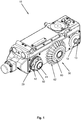
- Fig. 1 shows an example of an inspection or cleaning trolley 10, which may be configured, for example, as a camera carriage for the inspection of ducts or pipelines.
- an inspection or cleaning trolley 10 which may be configured, for example, as a camera carriage for the inspection of ducts or pipelines.
- FIG. 1 shown illustration of the inspection or cleaning trolley 10, only the essential elements of the present invention of the inspection trolley are shown.
- the inspection or cleaning cart 10 may have further structures or attachments, not shown here.
- inspection or cleaning cart 10 has three wheel or crawler axles 12.
- an inspection or cleaning trolley 10 may also have more than three or fewer than three trolley axles 12.
- the substantially cylindrical trolley axle 12 has a radial pin 13 which serves as an anti-rotation device for an axle adapter 20 mounted on the trolley axle 12 of a quick-change system 30 according to the invention.
- the axle end portion of the trolley axle 12 may also have a rectangular or square cross-section, so that an anti-rotation of an attached axle adapter 20 is already given due to the geometry of the axle end and the radial pin 13 shown here can also be dispensed with.
- an axle adapter 20 is arranged on the left wheel axle, with an in Fig. 1 invisible screw is firmly connected to the trolley axle 12. Furthermore, an axial locking device is arranged on the left wheel axle or on the axle adapter 20, wherein in Fig. 1 a portion of the unlocking device 41 and locking elements 42 of the axial locking device are visible.
- a cover cap 50 Arranged on the axle adapter 20 or on the unlocking device 41 is a cover cap 50 which has a circular opening into which the unlocking device 41 protrudes and which prevents the unlocking device 41 from being released from the axle adapter 20.
- the wheel or a tire mounts 60 (for example a rim) is pushed all the way to the stop, wherein the pushed-on tire receptacle 60 is locked axially by means of the locking elements 42, so that the tire receptacle 60 can not detach itself from the axle adapter 20 on its own.
- the locking elements 42 in this case engage in recesses provided for the tire holder.
- axle adapter 20 Due to the geometry of the axle adapter 20 and the inner cross section of the tire holder 60, it is also ensured that the mounted tire receivers can not rotate relative to the axle adapter 20 about the longitudinal axis of the vehicle axle.
- a tire 62 is arranged on the tire receptacle 60, wherein the tire receptacle 60 with the tire 62 can be removed from the axle adapter 20 by actuating the unlocking device 41, as will be described in more detail below.
- the tires 62 may have different outer diameters or different profiles.
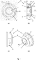
- Fig. 2 shows a quick-change system according to the invention with an axle adapter and a locking device arranged thereon, wherein in Figure (a) a view from the front, in Figure (b) a sectional view along the section axis AA, in Figure (c) a side view and in Figure (d) a perspective view of the quick-change system are shown.
- the quick-change system according to the invention comprises an axle adapter 20 which is fastened to the trolley axle, wherein the axle adapter can be releasably or firmly connected to the trolley axle. Furthermore, the quick-change system according to the invention comprises a locking device which comprises a number of locking elements 42 and an unlocking device 41 cooperating with the locking elements 42. The locking elements 42 can be brought from a locking position to an unlocking position with the aid of the unlocking device 41, as with reference to FIG Fig. 7 will be described in more detail.
- the axle adapter 20 has a circumferential side wall 21, wherein the side wall may have a circular outer profile. It is advantageous, however, if a lower portion, ie a side facing the trolley axle 21 of the side wall has no circular outer profile, but an outer profile, which prevents rotation of the pushed onto the axle adapter 20 tire receptacle about the longitudinal axis LA of the axle adapter relative to the axle adapter.
- the side wall 21 has an outer profile with three substantially straight sections, two straight sections each being connected by a curved section. The geometry of the outer profile of the side wall 21 thus forms an effective Anti-rotation of the tire mounts against the axle adapter. Further geometries of a side wall 21 of an axle adapter according to the invention are shown in FIG Fig. 11 shown.
- a locking element 42 is arranged in the side wall 21 of the axle adapter.
- the through holes 22 have a round cross section.
- the locking elements 42 are designed as cylindrical pins or pins. According to the invention, the locking elements 42 are arranged movable relative to the through hole 22 in the through hole 22, wherein the locking elements 42 are movable from a locking position to an unlocking position. When the locking elements 42 are in a locking position, they protrude at least partially out of the through hole 22 and engage in a recess provided on the tire receptacle 60, so that the locking elements 22 axially lock the tire receptacle.
- a number of spring elements 43 are provided in the axle adapter 20, wherein each locking element 42, a spring element 43 is associated.
- the spring force of the spring element 43 causes the locking element 42 assigned to it to be pressed essentially radially outward. This makes it possible that the tire holder is automatically locked axially after the complete sliding onto the axle adapter.
- the quick-change system has three locking elements 42. Depending on the requirements, however, more than three or less than three locking elements 42 may be provided. Preferably, the locking elements 42 are arranged distributed uniformly in the circumferential direction.
- the through holes 22 and the locking elements 42 are inclined by a certain angle to the transverse axis QA2, which brings about particular advantages, as with reference to FIG Fig. 8 and Fig. 9 is explained in more detail.
- the outer end portion of the locking elements 42 is configured so that upon pushing the tire holder on the axle adapter they are pressed by the Reifenaufhahme against the spring force of the spring element 43 radially inward, as with reference to Fig. 8 is explained in more detail.
- the unlocking element 42 has at the inner end portion a blind bore or a blind hole into which the spring element 43 engages at least partially.
- the locking element 42 opposite end portion of the spring element 43 engages at least partially in an inner portion 22 b of the through hole 22, wherein the through hole 22 is at least partially interrupted by a circumferential movement space 25.
- an unlocking device 41 of the locking device is arranged, wherein the unlocking device 41 is movable in the axial direction along the longitudinal axis LA.
- the unlocking device 41 has a circumferential side wall 47, which is disposed within the side wall 21 of the axle adapter 20 and engages in the circumferential movement space 25. According to the invention, the unlocking device 41 cooperates with the locking elements 42, such that when moving the unlocking device 41 in the axial direction along the longitudinal axis LA, the locking elements can be brought from the locking position into an unlocking position in which the tire holder is axially unlocked and removed from the axle adapter 20 can be.
- the interaction of the unlocking device with the locking elements will with reference to Fig. 7 explained in more detail.
- a cap 50 is arranged on the axle adapter 20, which secures the unlocking device 41 to the axle adapter.
- the cap 50 has an opening into which the unlocking device 41 at least partially protrudes, so that the unlocking device 41 can be manually operated from the outside.
- the cap 50 may be secured with mounting screws on the side wall of the axle adapter 20. Alternatively, the cap can also be screwed by means of a screw thread on the axle adapter.
- the cap In the region in which the unlocking device protrudes into the opening of the cap 50, the cap has a circumferential sealing element 70 in order to prevent dust or liquid from getting into the interior of the axle adapter 20.
- Corresponding circumferential sealing elements are also provided in the through-holes 22, so that no dust or liquid can get into the interior of the axle adapter 20 between the wall of the through-hole and the wall of the locking elements.
- the axle adapter 20, the unlocking device 41, the locking element 42 and the cap 50 may be made of a stable, preferably highly stable, plastic.
- these elements of the quick-change system according to the invention can also be made of a metal.
- the quick-change system according to the invention can also be produced in a 3D printing process.
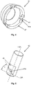
- FIG. 3 shows a locking device 40 according to the invention, wherein in Figure (a) is a view from the front, in Figure (b) is a sectional view, in Figure (c) is a perspective view from behind and in Figure (d) is a perspective view from the front.
- the locking device 40 comprises a number of locking elements 42 and an unlocking device 41 cooperating with the locking elements.
- the unlocking device 41 is moved inwardly along the longitudinal axis LA (indicated by the arrow)
- the locking elements 42 are brought from a locking position into an unlocking position or the locking elements 42 are released so that they can be brought into an unlocking position.
- the unlocking device may have a substantially circular cross section (other cross sections are also possible), wherein in the side wall 47 of the unlocking 41 edge-side slots 44 are provided.
- the locking elements 42 have wall-side recesses 45, wherein the locking elements in the region of these recesses 45 are brought into engagement with the slots 44.
- the recesses 45 of the locking elements 42 have a side wall which is inclined by a certain angle to the transverse axis of the locking element.
- the unlocking element 41 here has a circular cross-section.
- the unlocking device 41 may also have a different cross section, in which in the side wall 47 also a number of edge-side slots 44 are provided.
- Fig. 4 shows an unlocking device 41 according to the invention in a perspective view from behind or from below.
- Clearly visible here are provided in the side wall 47 slots 44, wherein the slots 44 and the Side walls of the slots 44 have end portions 44 a, which are brought into engagement with the recesses 45 of the locking elements 42.
- the end portions 44a are designed here sloping inwards, wherein the angle of the end portions 44a substantially corresponds to the angle of the oblique side wall of the recess 45 of the respective locking element 42.
- the unlocking device 41 is preferably designed in one piece or in one piece.
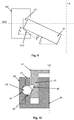
- Fig. 5 shows an embodiment of a locking element 42 according to the invention.
- the locking element 42 is designed here as a pin or bolt and has a substantially cylindrical shape with a circular cross-section.
- a recess 45 is provided on the pin 42, wherein advantageously two opposite identically configured recesses 45 are provided.
- two side walls are formed, wherein at least one side wall 45a is at an angle ⁇ to the transverse axis QA of the locking element 42.
- the oblique configuration of the side wall 45a is necessary so that the locking element 42 is pushed radially inwardly when moving the unlocking device 41.
- the locking element 42 may also have a different cross section than a circular cross section. It is only important that a recess 45 is provided on the locking element 42, which has at least one oblique side wall 45 a.
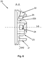
- Fig. 6 shows an axle adapter 20 according to the invention in a sectional view along the section axis AA (see Fig. 2 ).
- the side wall 21 which extends up to a guide pin arranged within the side wall Extends, wherein the lying in the guide pin 23 section 22 b of the through hole 22 is designed as a blind hole or blind hole.
- the spring element 43 is arranged in the blind bore 22b.
- a circumferential movement space 25 is formed, in which the side wall 47 of the unlocking device 41 at least partially engages.
- the guide pin 23 in this case forms a guide for the unlocking device 41 when it is moved in the axial direction relative to the axle adapter 20.
- an axial bore 24 may be provided, in which a fastening screw for attaching the axle adapter to the wheel axle 12 may be introduced.
- the through hole 22 is inclined by a certain angle to the transverse axis QA2 of the axle adapter 20 to the outside. This has certain advantages, as with respect to Fig. 9 is explained in more detail.
- the longitudinal axis of the through hole 22 can also run parallel to the transverse axis QA2 of the axle adapter 20.
- the outer end portion of the locking element 42 must be configured differently in order to optimally ensure a movement of the locking element radially inwardly when pushing the tire holder onto the axle adapter 20.
- the axle adapter 20 can also be designed in one piece or in one piece.
- Fig. 7 shows two different examples to illustrate the interaction of the unlocking device 41 with the locking element 42, wherein in Figure (a) an obliquely arranged locking element and in Figure (b) a substantially horizontally disposed locking element is used.
- the locking element 42 has a transverse to the longitudinal axis of the locking element recess 45 which is bounded inwardly by an oblique side wall 45a.
- a respective locking element 42 is shown, which is in a locking position.
- An end portion 44a of the slot 44 of the unlocking device 41 is here at the upper end of the oblique side wall 45a.
- the unlocking device 41 has been moved completely downwards and has reached its end position, whereby the locking elements 42 are in an unlocked position.
- the locking elements 42 protrude only slightly or not at all from the respective through hole of the side wall 21 of the axle adapter 20 out.
- the locking elements 42 again move radially outward, which is effected, for example, by the spring force of a spring element (not illustrated here).
- the lower end portions 44a of the slot 44 may be chamfered on the inside, the chamfered portion being substantially parallel to the oblique side wall 45a. As a result, the force required for displacing the unlocking device 41 along the longitudinal axis LA downwards is minimized or optimized.
- the inclined side wall 45a may be additionally provided with a lubricant to reduce the friction between the end portion 44a of the slot 44 and the oblique side wall 45a.
- Fig. 8 shows a cross section through an axle adapter 20 and a tire seat 60 to illustrate the principle of action of the axial locking device when pushing the tire holder on the axle adapter.
- the through-hole 22 in the side wall 21 of the axle adapter 20 is inclined outwards at a certain angle to the transverse axis of the axle adapter, so that the locking element 42 arranged in the through-hole is pushed radially inwards during unlocking.
- the tire seat 60 in an initial position of the assembly process.
- a lower or one of the trolley axle facing portion of the tire seat 60 is pressed against the outer bottom surface of the locking element 42, which is inclined due to the oblique arrangement of the locking element 42 at a certain angle to the tire seat 60.
- the tire receptacle 60 presses against the locking element 42, as a result of which the tire receptacle 60 is pushed radially inward or is displaced.
- the locking element 42 is again pushed radially obliquely outward, which is accomplished by a spring, not shown here, and pushed into a recess provided on the inner wall of the tire receiving recess. As soon as the locking element 42 engages in the recess 61, which is Tire holder 60 axially locked so that a release of the tire holder of the axle adapter without actuation of the unlocking device is no longer possible.
- Fig. 9 shows an advantageous arrangement of the locking element 42 relative to the tire seat 60 and an advantageous embodiment of the recess 61 in the tire holder 60th
- the tire receptacle 60 has on the inner wall on at least partially circumferential gate recess 61 which is laterally bounded by two side walls.
- the axially inner side or the side facing the trolley axle 61a is inclined by a first angle ⁇ to the transverse axis QA2 of the tire seat, so that the axially inner side wall 61a forms an inclined surface.
- the first angle ⁇ is less than 90 °.
- the locking element 42 which is designed here as a cylindrical pin or pin, is inclined by a second angle ⁇ to the transverse axis QA2 of the tire holder 60, wherein the first angle ⁇ is greater than the second angle ⁇ , so that the locking element 42 at an angle ⁇ to the axially inner side wall 61a.
- the angle ⁇ ie, the difference between the first angle ⁇ and the second angle ⁇ is chosen so that between the axially inner side wall 61 a and the locking element 42 in a locking position results in a traction, the release of the tire holder 60 of the axle adapter 20 prevented.
- the angle ⁇ between the inner side wall 61a and the locking element 42 is selected such that self-locking results between the locking element 42 and the side wall 61a.
- the angle ⁇ is to be chosen so that the force acting on the locking element 42 spring force of the spring element, not shown here is sufficient to push the locking member 42 along the inner side wall 61 a in the gate recess 61.
- the tire holder Due to the oblique arrangement of the locking element 42, the outer bottom surface is also inclined by a certain angle, and the angle ⁇ between the inner side wall 61a and the locking member 42, the tire holder can be pushed onto the axle adapter without the unlocking device 41 must be operated with which the locking elements 42 can also be pushed radially inward. For the installation of the tire holder 60, this only has to be pushed onto the axle adapter 20 until the locking elements 42 engage or engage in the slot recess 61. For this purpose, neither a tool is necessary, nor must the locking element 42 are actuated.
- the unlocking device 41 In order to release the tire seats 60 again from the axle adapter 20, the unlocking device 41 must be pressed, whereby the locking elements are pushed radially inward or pulled out of the sliding recess 61, as with reference to Fig. 7 explained.
- Fig. 10 shows an alternative embodiment of a quick change system according to the invention.
- a quick change system according to the invention.
- a ball as a locking element 42 is provided instead of a pin or bolt a ball as a locking element 42 is provided.
- the ball 42 is disposed in the through hole 22 of the side wall 21 of the axle adapter 20, wherein the through hole is preferably configured so that the ball 42 can not fall out radially outwardly from the through hole 22.
- the at least partially encircling guide recess 61 on the inner wall of the tire holder 60 essentially has a semicircular cross-section, the radius of which substantially corresponds to the radius of the ball.
- the ball 42 is displaced by means of the unlocking device 41 in the gate recess 61, so that the tire holder 60 is axially locked.
- the unlocking device 41 is moved in the axial direction to the outside, which can be accomplished, for example, with one of the unlocking device 41 associated spring element.
- the unlocking device For unlocking the unlocking device is moved inwardly in the axial direction, wherein a recess 48 in the side wall 47 of the unlocking device 41, the ball 42 releases, so that it is displaced radially inwardly when the tire holder 60 is withdrawn from the axle adapter 20.
- the recess 48 in the side wall 47 is configured such that the depth of the recess increases in the axial direction outwards, so that a substantially wedge-shaped recess 48 is formed.
- FIG. 1 A hook as a locking element 42 may be mounted in the through hole 42 at a rotational axis, wherein when locking the hook is rotated about this axis of rotation to the outside and engages with a hook member in a recess 61 of the tire seat 60.
- the side wall 47 of the unlocking device 41 can be designed in this way be as related to Fig. 10 shown.
- the recess 48 in the side wall 47 forms a region in which the hook takes place when unlocking.
- the hook is again pivoted out of the through hole 22 and held by the lower portion of the side wall 47 in the locking position.
- Fig. 11 shows various embodiments of a side wall 21 of an axle adapter 20 and various embodiments of an inner wall and a rear portion of an inner wall of a tire housing.
- the rear section of the tire receptacle corresponds to the side wall 21 of the axle adapter 20, so that the tire receptacle 60 is radially locked, ie the tire receptacle 60 is not rotatable relative to the axle adapter about the longitudinal axis of the axle adapter.
- the side wall 21 has a substantially circular outer profile, wherein at one point of the side wall, a radial pin is provided, which engages in a radial groove of the tire seat 60.
- This embodiment is particularly advantageous if the locking elements 42 are arranged irregularly in the circumferential direction of the axle adapter 20 and the tire holder 60 can therefore be pushed onto the axle adapter 20 only in a single specific position.
- Figure (b) shows an axle adapter 20 in which the side wall 21 has an elliptical or oval outer contour.
- the Reifenaufhahme 60 can be pushed in two different positions on the axle adapter 20.
- axle adapter 20 is shown, the side wall 21 has a substantially rectangular outer profile.
- the figure (d) shows an axle adapter 20 with a side wall 21, which has an outer profile in the form of a gear or gears.
- the figure (e) shows an axle adapter 20 with a side wall 21 which has a substantially triangular outer profile, wherein the corners are rounded.
- the tire receptacle 60 can be screwed onto the axle adapter 20 by means of a thread.
- Fig. 12 shows example of a tire 62 on a tire seat 60 in a front view and in a sectional view along a sectional axis AA.
- the tire 62 is here designed so that it is particularly suitable for pipes or sewer pipes with a smaller diameter.
- the tire on an inclined tire shoulder, which has a certain width.
- the tire shoulder When driving a smaller diameter channel, the tire shoulder substantially forms the tread of the tire, while when driving a larger diameter channel, the radially outer surface adjacent to the tire shoulder serves as a tread.
- sectional view of the trolley axis facing portion of the tire seat 60 is shown, which is adapted in shape to the side wall 21 of the axle adapter, thus preventing rotation of the tire holder about the longitudinal axis of the trolley axis relative to the axle adapter.
- This section follows axially outwardly the circumferential gate recess 61, in which the locking elements can be brought into engagement.
- the tire 62 may be made of a rubber or a preferably abrasion resistant plastic.
- the tire may also have a different running profile than in Fig. 12 shown.
Landscapes
- Engineering & Computer Science (AREA)
- Mechanical Engineering (AREA)
- General Engineering & Computer Science (AREA)
- Chemical & Material Sciences (AREA)
- Combustion & Propulsion (AREA)
- Tires In General (AREA)
- Handcart (AREA)
- Vehicle Cleaning, Maintenance, Repair, Refitting, And Outriggers (AREA)
Description
Die Erfindung betrifft ein Wechselsystem für Fahrwagenräder eines Inspektionswagens zum schnellen Wechseln von Fahrwagenrädern, eine Reifenaufnahme für ein erfindungsgemäßes Schnellwechselsystem sowie einen Inspektionswagen mit einer Anzahl erfindungsgemäßer Schnellwechselsysteme.The invention relates to a change system for vehicle wheels of an inspection trolley for quick change of trolley wheels, a tire holder for a quick change system according to the invention and an inspection trolley with a number of quick change systems according to the invention.
Für die Inspektion von Kanälen, insbesondere Abwasserkanälen, Anschlusskanälen oder sonstiger abwassertechnischer Anlagen, wird herkömmlicherweise ein selbstfahrender Wagen bzw. Inspektionswagen eingesetzt. Ähnliche Wagen bzw. Fahrzeuge werden auch zu Reinigungszwecken in den Kanälen eingesetzt. Die Inspektionswagen bzw. Reinigungswagen weisen hierzu Räder auf, mit denen ein Bewegen des Wagens im Kanal bzw. in der Rohrleitung bewerkstelligt wird. In Abhängigkeit beispielsweise des Kanal- bzw. Rohrdurchmessers muss der Inspektions- bzw. Reinigungswagen mit Rädern bestückt werden, die vorzugsweise eine an den Rohr- bzw. Kanaldurchmesser angepasste Bereifung aufweisen. Hierbei ist es wünschenswert, die Räder samt der Bereifung lösbar an den Fahrwagenachsen anzuordnen, um ein Austauschen der Räder zu ermöglichen, sodass ein Inspektions- bzw. Reinigungswagen in unterschiedlichen Kanälen bzw. Rohren verwendet werden kann.For the inspection of canals, in particular sewers, connecting ducts or other wastewater treatment plants, conventionally a self-propelled trolley or inspection trolley is used. Similar cars or vehicles are also used for cleaning purposes in the channels. For this purpose, the inspection trolleys or cleaning trolleys have wheels with which a movement of the trolley in the duct or in the pipeline is accomplished. Depending on, for example, the duct or pipe diameter, the inspection or cleaning trolley must be equipped with wheels which preferably have a tire adapted to the pipe or duct diameter. In this case, it is desirable to detachably arrange the wheels together with the tires on the trolley axles in order to enable the wheels to be exchanged, so that an inspection or cleaning trolley can be used in different ducts or pipes.
Im Stand der Technik ist es bekannt, die Räder eines Inspektions- bzw. Reinigungsfahrzeuges mit einer oder mehreren Schrauben an der Fahrwagenachse zu befestigen. Dies hat allerdings den Nachteil, dass einerseits Werkzeuge zum Lösen der Schrauben benötigt werden und andererseits die gelösten Schrauben und gegebenenfalls Unterlegscheiben leicht verloren gehen können, sodass es zu Ausfallzeiten des Inspektions- bzw. Reinigungswagens kommen kann.In the prior art, it is known to attach the wheels of an inspection or cleaning vehicle with one or more screws on the trolley axle. However, this has the disadvantage that on the one hand tools for loosening the screws are needed and on the other hand, the dissolved screws and possibly washers can easily be lost, so it can lead to downtime of the inspection or cleaning car.
Zudem nimmt der Wechsel der Fahrwagenräder eine gewisse Zeit in Anspruch, weil für jedes Rad die jeweiligen Befestigungsschrauben gelöst und nach dem Wechsel des Rades wieder eingeschraubt werden müssen. Ein weiterer Nachteil liegt darin, dass, sofern die benötigten Werkzeuge für den Radwechsel nicht zur Verfügung stehen, ein Radwechsel überhaupt nicht vorgenommen werden kann.In addition, the change of the vehicle wheels takes a certain amount of time, because for each wheel, the respective fixing screws must be loosened and screwed in again after changing the wheel. Another disadvantage is that, if the tools required for the wheel change are not available, a wheel change can not be made at all.
Aus der
- die Verriegelungseinrichtung zumindest ein Verriegelungselement und eine mit dem zumindest einen Verriegelungselement zusammenwirkende Entriegelungseinrichtung umfasst, wobei das zumindest eine Verriegelungselement in einer Verriegelungsposition die Reifenaufnahme auf dem Achsadapter axial verriegelt, und
- die Entriegelungseinrichtung und das zumindest eine Verriegelungselement so zusammenwirken, dass beim Bewegen der Entriegelungseinrichtung das zumindest eine Verriegelungselement von der Verriegelungsposition in eine Entriegelungsposition bringbar ist, in der die Reifenaufnahme axial entriegelt ist,
- the locking device comprises at least one locking element and an unlocking device interacting with the at least one locking element, wherein the at least one locking element axially locks the tire mount on the axle adapter in a locking position, and
- the unlocking device and the at least one locking element cooperate in such a way that, when the unlocking device is moved, the at least one locking element can be brought from the locking position into an unlocking position in which the tire mount is unlocked axially,
Aufgabe der vorliegenden Erfindung ist es daher, Lösungen bereitzustellen, mit denen Räder eines Inspektions- bzw. Reinigungswagens, insbesondere eines Kanalinspektions- und/oder Kanalreinigungssystems, schneller, komfortabler, sicherer und insbesondere Werkzeuglos gewechselt werden können.The object of the present invention is therefore to provide solutions with which wheels of an inspection or cleaning trolley, in particular a sewer inspection and / or sewer cleaning system, can be changed faster, more comfortably, more safely and in particular without tools.
Erfindungsgemäß wird diese Aufgabe mit einem Schnellwechselsystem für Fahrwagenräder, insbesondere für Fahrwagenräder eines Inspektionswagens, insbesondere Kanalinspektions- und/oder Kanalreinigungswagen, eine Reifenaufnahme für ein erfindungsgemäßes Schnellwechselsystem, eine Schnellwechseleinrichtung mit einem erfindungsgemäßen Schnellwechselsystem und einer erfindungsgemäßen Reifenaufnahme, sowie mit einem Inspektionswagen mit einer Anzahl von erfindungsgemäßen Schnellwechselsystemen, gemäß den unabhängigen Ansprüchen gelöst. Vorteilhafte Ausgestaltungen und Weiterbildungen der Erfindung sind in den jeweiligen abhängigen Ansprüchen angegeben.This object is achieved with a quick-change system for vehicle wheels, especially for vehicle wheels of an inspection car, especially Kanalinspektions- and / or sewer cleaning car, a tire holder for a quick change system according to the invention, a quick-change device with a quick change system according to the invention and a tire holder according to the invention, and with an inspection car with a number of Quick change systems according to the invention, solved according to the independent claims. Advantageous embodiments and further developments of the invention are specified in the respective dependent claims.
Bereitgestellt wird demnach ein Schnellwechselsystem für Fahrwagenräder, insbesondere für Fahrwagenräder eines Inspektionswagens, insbesondere Kanalinspektions- und/oder Kanalreinigungswagen, umfassend einen Achsadapter und eine Verriegelungseinrichtung zum axialen Verriegeln einer Reifenaufnahme auf dem Achsadapter, wobei
- die Verriegelungseinrichtung zumindest ein Verriegelungselement und eine mit dem zumindest einen Verriegelungselement zusammenwirkende Entriegelungseinrichtung umfasst, wobei das zumindest eine Verriegelungselement in einer Verriegelungsposition die Reifenaufnahme auf dem Achsadapter axial verriegelt,
- die Entriegelungseinrichtung und das zumindest eine Verriegelungselement so zusammenwirken, dass beim Bewegen der Entriegelungseinrichtung das zumindest eine Verriegelungselement von der Verriegelungsposition in eine Entriegelungsposition bringbar ist, in der die Reifenaufnahme axial entriegelt ist, und
- in einer Seitenwandung des Achsadapters zumindest ein Durchgangsloch vorgesehen ist, in dem das Verriegelungselement relativ zum Durchgangsloch bewegbar angeordnet ist, wobei das Verriegelungselement in der Verriegelungsposition zumindest teilweise aus dem Durchgangsloch herausragt und dadurch die Reifenaufnahme axial verriegelt.
- the locking device comprises at least one locking element and an unlocking device interacting with the at least one locking element, wherein the at least one locking element axially locks the tire mount on the axle adapter in a locking position,
- the unlocking device and the at least one locking element cooperate so that when moving the unlocking the at least one locking element can be brought from the locking position into an unlocking position in which the tire receptacle is unlocked axially, and
- in a side wall of the axle adapter, at least one through hole is provided, in which the locking element is arranged movable relative to the through hole, wherein the locking element in the locking position at least partially protrudes from the through hole and thereby axially locking the tire holder.
Vorzugsweise ist die Entriegelungseinrichtung in axialer Richtung entlang der Längsachse des Schnellwechselsystems bewegbar. Alternativ kann die Entriegelungseinrichtung auch um die Längsachse des Schnellwechselsystems drehbar sein, um das zumindest eine Verriegelungselement von der Verriegelungsposition in die Entriegelungsposition zu bringen.Preferably, the unlocking device is movable in the axial direction along the longitudinal axis of the quick-change system. Alternatively, the unlocking device can also be rotatable about the longitudinal axis of the quick-change system in order to bring the at least one locking element from the locking position into the unlocking position.
Damit ist es möglich, die Reifenaufnahme, etwa eine Felge, werkzeuglos von dem Achsadapter abzunehmen. Hierzu muss lediglich die Entriegelungseinrichtung in axialer Richtung bewegt werden oder um ihre Längsachse gedreht werden, um das zumindest eine Verriegelungselement in eine Entriegelungsposition zu bringen. Das Bewegen in axialer Richtung kann beispielsweise durch Drücken auf die Entriegelungseinrichtung bewerkstelligt werden.This makes it possible to remove the tire holder, such as a rim, without tools from the axle adapter. For this purpose, only the unlocking device must be moved in the axial direction or rotated about its longitudinal axis in order to bring the at least one locking element in an unlocked position. The movement in the axial direction can be accomplished, for example, by pressing on the unlocking device.
Das zumindest eine Verriegelungselement kann einen Stift, einen Zapfen, zumindest eine Kugel, einen Haken oder einen Magneten umfassen.The at least one locking element may comprise a pin, a pin, at least one ball, a hook or a magnet.
Der Stift oder der Zapfen kann zumindest eine wandungsseitige Aussparung aufweisen, die im Wesentlichen quer zur Längsachse des Stiftes bzw. des Zapfens verläuft.The pin or the pin may have at least one wall-side recess, which extends substantially transversely to the longitudinal axis of the pin or of the pin.
Vorteilhaft ist es, wenn die wandungsseitige Aussparung eine schräge Seitenwandung aufweist, die in einem Winkel zur Querachse des Stiftes bzw. des Zapfens angeordnet ist bzw. verläuft.It is advantageous if the wall-side recess has an oblique side wall which is arranged or extends at an angle to the transverse axis of the pin or of the pin.
Die Entriegelungseinrichtung kann als Entriegelungskappe mit einer umlaufenden Seitenwandung ausgestaltet sein, wobei die Entriegelungseinrichtung derart relativ zum Achsadapter anordenbar ist, dass die Seitenwandung der Entriegelungskappe zumindest teilweise innerhalb der Seitenwandung des Achsadapters angeordnet ist und dass die Entriegelungskappe in axialer Richtung entlang der Längsachse des Schnellwechselsystems relativ zum Achsadapter bewegbar ist.The unlocking device can be configured as an unlocking cap with a circumferential side wall, wherein the unlocking device can be arranged relative to the axle adapter, that the side wall of the Entriegelungskappe is at least partially disposed within the side wall of the axle adapter and that the Entriegelungskappe in the axial direction along the longitudinal axis of the quick-change system relative to Axle adapter is movable.
In der Seitenwandung der Entriegelungskappe kann zumindest ein randseitiger Schlitz vorgesehen sein, in den der Stift bzw. der Zapfen im Bereich seiner wandungsseitigen Aussparung in Eingriff bringbar ist. Die Breite des Schlitzes ist hierbei vorzugsweise kleiner als der Durchmesser des Stiftes bzw. des Zapfens.In the side wall of the Entriegelungskappe can be provided at least one edge-side slot into which the pin or the pin in the region of its wall-side recess can be brought into engagement. The width of the slot is in this case preferably smaller than the diameter of the pin or of the pin.
Die Entriegelungskappe und der Stift bzw. der Zapfen wirken vorzugsweise so zusammen, dass beim Bewegen der Entriegelungskappe in axialer Richtung ein Endabschnitt des Schlitzes auf die schräge Seitenwandung der wandungsseitigen Aussparung des Stiftes bzw. des Zapfens wirkt und dadurch den Stift bzw. den Zapfen radial nach innen bewegt. Damit wird es in vorteilhafter Weise möglich, die Reifenaufnahme werkzeuglos von dem Achsadapter abzunehmen, weil sich die radial nach innen bewegten Verriegelungselemente bzw. Stifte bzw. Zapfen in einer Entriegelungsposition befinden und die Reifenaufnahme damit axial entriegelt ist.The Entriegelungskappe and the pin or the pin preferably act together so that when moving the Entriegelungskappe in the axial direction, an end portion of the slot acts on the oblique side wall of the wall-side recess of the pin or the pin and thereby the pin or the pin radially moved inside. This makes it possible in an advantageous manner to remove the tire holder without tools from the axle adapter, because the radially inwardly moved locking elements or pins or pins are in an unlocked position and the tire holder is thus axially unlocked.
Damit ist es in vorteilhafter Weise möglich, eine Reifenaufnahmen sowohl werkzeuglos von dem Achsadapter abzunehmen als auch werkzeuglos auf dem Achsadapter anzubringen.Thus, it is possible in an advantageous manner, both tool-free to remove a tire mounts from the axle adapter as well as to attach tool-less on the axle adapter.
In einer Ausgestaltung der Erfindung ist dem Verriegelungselement ein Federelement zugeordnet, dessen Federkraft das Verriegelungselement radial nach außen drückt. Damit wird gewährleistet, dass eine auf den Achsadapter aufgeschobene Reifenaufnahme automatisch axial verriegelt ist.In one embodiment of the invention, the locking element is associated with a spring element whose spring force presses the locking element radially outward. This ensures that a wheel adapter pushed onto the axle adapter is automatically locked axially.
Wenn als Verriegelungselemente Kugeln vorgesehen sind, ist es vorteilhaft, wenn die Kugeln in der Verriegelungsposition in eine Kulissenaussparung an der Innenwandung der Reifenaufnahme eingreifen. Den Kugeln kann ebenfalls ein Federelement zugeordnet sein, die die Kugeln radial nach außen drücken.If balls are provided as locking elements, it is advantageous if the balls engage in the locking position in a sliding recess on the inner wall of the tire holder. The balls may also be associated with a spring element, which press the balls radially outward.
Wenn als Verriegelungselemente Kugeln vorgesehen sind, ist es vorteilhaft, wenn an der Außenwand der Seitenwandung der Entriegelungseinrichtung eine Aussparung vorgesehen ist, wobei die Tiefe der Aussparung in axialer Richtung zunimmt und wobei die Kugeln in die Aussparung in Eingriff gebracht werden können.If balls are provided as locking elements, it is advantageous if a recess is provided on the outer wall of the side wall of the unlocking device, wherein the depth of the recess increases in the axial direction and wherein the balls can be brought into the recess in engagement.
Bei Verwendung von Kugeln als Verriegelungselemente ist es vorteilhaft, wenn bei einem axialen Bewegen der Entriegelungseinrichtung relativ zum Achsadapter und
- in Richtung zur geringeren Tiefe der Aussparung der Entriegelungseinrichtung die Kugel in die Entriegelungsposition bringbar ist und
- in Richtung zur größeren Tiefe der Aussparung der Entriegelungseinrichtung die Aussparung ein Bewegen der Kugel in die Verriegelungsposition bewirkt.
- in the direction of the lesser depth of the recess of the unlocking device, the ball can be brought into the unlocking position and
- in the direction of the greater depth of the recess of the unlocking device, the recess causes a movement of the ball in the locking position.
In einer Ausgestaltung der Erfindung weist der Achsadapter einen koaxialen Führungsbolzen auf, der in axialer Richtung in eine dafür vorgesehene Aussparung der Entriegelungseinrichtung eingreift.In one embodiment of the invention, the axle adapter on a coaxial guide pin which engages in the axial direction in a recess provided for this purpose the unlocking device.
In dem Führungsbolzen können Sackbohrungen zur Aufnahme der Federelemente vorgesehen sein.In the guide pin blind holes may be provided for receiving the spring elements.
Vorzugsweise sind die Sackbohrungen koaxial zu den Durchgangslöchern der Seitenwandung des Achsadapters angeordnet. Die Sackbohrungen weisen vorteilhafterweise den gleichen Durchmesser wie die Durchgangslöcher auf. Damit ist gewährleistet, dass die in den Durchgangslöchern angeordneten Verriegelungselemente gegen die Federkraft des Federelementes zumindest teilweise in die Sackbohrungen verschoben werden können.Preferably, the blind holes are arranged coaxially with the through holes of the side wall of the axle adapter. The blind holes advantageously have the same diameter as the through holes. This ensures that the arranged in the through holes locking elements against the spring force of the spring element can be moved at least partially into the blind holes.
In einer vorteilhaften Ausgestaltung des erfindungsgemäßen Schnellwechselsystems bildet die Entriegelungseinrichtung einen Druckknopf zum axialen Entriegeln der Reifenaufnahme, wobei durch Drücken des Druckknopfes die Verriegelungselemente von einer Verriegelungsposition in eine Entriegelungsposition bringbar sind bzw. die Verriegelungselemente freigegeben werden, damit diese von einer Verriegelungsposition in eine Entriegelungsposition gebracht werden können.In an advantageous embodiment of the quick-change system according to the invention, the unlocking device forms a push button for axially unlocking the tire, wherein the locking elements can be brought from a locking position to an unlocking by pressing the push button or the locking elements are released so that they are brought from a locking position to an unlocked position can.
In einer vorteilhaften Ausgestaltung des erfindungsgemäßen Schnellwechselsystems weist die Seitenwandung des Achsadapters zumindest bis zu einer vorbestimmten Höhe einen Außenquerschnitt auf, der mit einem Innenquerschnitt der Reifenaufnahmen korrespondiert und ein Drehen der Reifenaufnahmen um die Längsachse des Schnellwechselsystems relativ zum Achsadapter verhindert. Damit wird die Reifenaufnahmen auf dem Achsadapter radial verriegelt, wobei auch hierfür keinerlei Werkzeuge notwendig sind.In an advantageous embodiment of the quick-change system according to the invention, the side wall of the axle adapter at least up to a predetermined height on an outer cross section, which with an inner cross section of Tire recordings corresponds and prevents rotation of the tire receivers around the longitudinal axis of the quick-change system relative to the axle adapter. Thus, the tire seats on the axle adapter is locked radially, which also no tools are necessary for this purpose.
In einer vorteilhaften Ausgestaltung ist der Außenquerschnitt ellipsenförmig, poligonförmig, drei- oder mehreckig, sternförmig, zahnradförmig oder rund mit einer radialen Passfeder ausgestaltet.In an advantageous embodiment, the outer cross section is elliptical, polygonal, triangular or polygonal, star-shaped, gear-shaped or round with a radial feather key.
Die Reifenaufnahme weist jeweils einen entsprechenden Innenquerschnitt auf.The tire holder has in each case a corresponding inner cross section.
Bereitgestellt wird durch die Erfindung ferner eine Reifenaufnahmen für ein erfindungsgemäßes Schnellwechselsystem, wobei die Reifenaufnahmen an einer Innenwandung eine zumindest teilweise umlaufende Kulissenaussparung aufweist, in die die Verriegelungselemente des Schnellwechselsystems in Eingriff bringbar sind und die Reifenaufnahme axial verriegeln, wenn die Reifenaufnahmen auf den Achsadapter des Schnellwechselsystems axial aufgeschoben wird.The invention further provides a tire mounts for a quick-change system according to the invention, wherein the tire mounts on an inner wall an at least partially circumferential gate recess into which the locking elements of the quick-change system are engageable and axially lock the tire holder when the tire mounts on the axle adapter of the quick-change system is pushed axially.
Die Kulissenaussparung kann einen im Wesentlichen halbkreisförmigen Querschnitt aufweisen. Dieser Querschnitt ist dann von Vorteil, wenn als Verriegelungselemente des Schnellwechselsystems Kugeln verwendet werden.The slide recess may have a substantially semicircular cross-section. This cross section is advantageous if balls are used as locking elements of the quick-change system.
In einer Ausgestaltung der erfindungsgemäßen Reifenaufnahme kann die umlaufende Kulissenaussparung zwei gegenüberliegende Seitenwandungen aufweisen, wobei eine axial innenliegende Seitenwandung der beiden Seitenwandungen um einen ersten Winkel zur Querachse der Reifenaufnahme, der kleiner als 90° ist, geneigt ist. Damit wird ermöglicht, dass ein Verriegelungselement, beispielsweise ein Zapfen oder Stift, während des Aufschiebens der Reifenaufnahme auf den Achsadapter langsam in die umlaufende Kulissenaussparung geschoben wird.In one embodiment of the tire holder according to the invention, the circumferential sliding recess may have two opposite side walls, wherein an axially inner side wall of the two side walls is inclined at a first angle to the transverse axis of the tire holder, which is smaller than 90 °. This makes it possible for a locking element, for example a pin or pin, to be pushed slowly into the circumferential slot recess during the sliding of the tire holder onto the axle adapter.
Das Verriegelungselement des Schnellwechselsystems kann um einen zweiten Winkel zur Querachse der Reifenaufnahme, der kleiner als 90° ist, geneigt sein, wobei der erste Winkel größer ist als der zweite Winkel. Dadurch ist gewährleistet, dass die auf den Achsadapter aufgeschobene Reifenaufnahme kein Spiel in axialer Richtung aufweist.The locking element of the quick-change system may be inclined by a second angle to the transverse axis of the tire seat, which is smaller than 90 °, the first angle being greater than the second angle. This ensures that the pushed onto the axle adapter tire holder has no play in the axial direction.
Es hat sich als vorteilhaft herausgestellt, wenn die Differenz zwischen dem ersten Winkel und dem zweiten Winkel so gewählt ist, dass sich zwischen der axial innenliegenden Seitenwandung und dem Verriegelungselement in einer Verriegelungsposition ein Kraftschluss ergibt, der ein Lösen der Reifenaufnahme von dem Achsadapter verhindert.It has proven to be advantageous if the difference between the first angle and the second angle is chosen so that there is a frictional connection between the axially inner side wall and the locking element in a locking position, which prevents detachment of the tire holder from the axle adapter.
Die dem Achsadapter bzw. der Fahrwagenachse zugewandte Seite der Reifenaufnahme kann einen Innenquerschnitt aufweisen, der mit einem Außenquerschnitt des Achsadapters des Schnellwechselsystems korrespondiert und ein Drehen der Reifenaufhahme um die Längsachse des Schnellwechselsystems relativ zum Achsadapter verhindert.The axle adapter or the carriage axis facing side of the tire receptacle may have an inner cross-section which corresponds to an outer cross-section of the axle adapter of the quick-change system and prevents rotation of Reifenaufhahme about the longitudinal axis of the quick-change system relative to the axle adapter.
Bereitgestellt wird durch die Erfindung des Weiteren eine Schnellwechseleinrichtung, umfassend ein erfindungsgemäßes Schnellwechselsystem und eine mit dem erfindungsgemäßen Schnellwechselsystem korrespondierende erfindungsgemäße Reifenaufnahme.The invention further provides a quick-change device comprising a quick-change system according to the invention and a tire receptacle according to the invention which corresponds to the quick-change system according to the invention.
Ferner wird durch die Erfindung ein Inspektionswagen, insbesondere Kanalinspektions- und/oder Kanalreinigungswagen, bereitgestellt, der eine Anzahl von erfindungsgemäßen Schnellwechselsystemen aufweist.Furthermore, the invention provides an inspection trolley, in particular a sewer inspection and / or sewer cleaning trolley, which has a number of quick-change systems according to the invention.
Die Schnellwechselsysteme sind vorzugsweise an den Radachsen des Inspektionswagens angebracht.The quick-change systems are preferably attached to the wheel axles of the inspection trolley.
In einer Ausgestaltung der Erfindung können die Schnellwechselsysteme lösbar an den Radachsen angebracht sein, beispielsweise mittels einer Schraubverbindung.In one embodiment of the invention, the quick-change systems can be releasably attached to the wheel axles, for example by means of a screw connection.
An einem Endabschnitt der Radachse kann ein radialer Zapfen angeordnet sein, der in eine entsprechende Aussparung des Achsadapters des Schnellwechselsystems in Eingriff bringbar ist und ein Drehen des Schnellwechselsystems um die Längsachse der Radachse relativ zur Radachse verhindert.At one end portion of the wheel axle, a radial pin may be arranged, which is engageable in a corresponding recess of the axle adapter of the quick-change system and prevents rotation of the quick-change system about the longitudinal axis of the wheel axle relative to the wheel axle.
Die Erfindung bringt insbesondere den Vorteil mit sich, dass Räder bzw. Fahrwagenräder werkzeuglos montiert, demontiert bzw. ausgewechselt werden können. Weil das Lösen von Schraubverbindungen zum Abnehmen von Fahrwagenrädern bzw. Reifenaufnahmen entfällt und weil das zu montierende Fahrwagenrad lediglich auf die Fahrwagenachse aufgeschoben werden muss und für die Demontage des Fahrwagenrades lediglich die Entriegelungseinrichtung in axialer Richtung verschoben werden muss ist ein Radwechsel auch wesentlich schneller bewerkstelligbar, als bei aus dem Stand der Technik bekannten Fahrwagenrädern.The invention has the particular advantage that wheels or trolley wheels can be mounted, dismounted or replaced without tools. Because the loosening of screw to remove Fahrwagenrädern or tire recordings deleted and because the Fahrwagenrad to be mounted only has to be postponed to the trolley axle and only the unlocking device must be moved in the axial direction for the dismantling of the Fahrwagenrades a wheel change is also much faster bewerkstelligbar than in known from the prior art Fahrwagenrädern.
Weil keinerlei Schrauben oder sonstigen lösbaren Teile an dem Schnellwechselsystem bzw. an der Reifenaufnahme vorhanden sind, können diese auch nicht verloren gehen, sodass Stillstandzeiten erheblich reduziert werden können.Because no screws or other detachable parts are present on the quick-change system or on the tire holder, they can not be lost, so that downtime can be significantly reduced.
Ein weiterer besonderer Vorteil liegt darin, dass sämtliche beweglichen Elemente an bzw. in dem Schnellwechselsystem angeordnet sind, während die Reifenaufnahme, die auf den Achsadapter des Schnellwechselsystems aufgeschoben wird, keinerlei beweglichen Teile aufweist und vorzugsweise einteilig bzw. einstückig ausgestaltet ist, was die Herstellungskosten bzw. den Herstellungsaufwand für erfindungsgemäße Reifenaufnahmen erheblich reduziert.Another particular advantage is that all movable elements are arranged on or in the quick-change system, while the tire holder, which is pushed onto the axle adapter of the quick-change system, has no moving parts and is preferably designed in one piece or in one piece, which reduces the manufacturing costs or costs ., The production costs for tire inventions invention significantly reduced.
Weitere Einzelheiten und Merkmale der Erfindung sowie konkrete, insbesondere vorteilhafte Ausführungsbeispiele der Erfindung ergeben sich aus der nachfolgenden Beschreibung in Verbindung mit der Zeichnung. Es zeigt:
- Fig. 1
- ein Beispiel eines Inspektions- bzw. Reinigungswagens mit drei Fahrwagenachsen zur Verdeutlichung des Grundprinzips des erfindungsgemäßen Schnellwechselsystems;
- Fig. 2
- einen erfindungsgemäßen Achsadapter in einer Ansicht von vorne, in einer Seitenansicht, in einer Schnittansicht und in einer perspektivischen Ansicht, wobei auch die axiale Verriegelungseinrichtung gezeigt ist;
- Fig. 3
- eine erfindungsgemäße axiale Verriegelungseinrichtung in einer Ansicht von vorne, in einer Schnittansicht, in einer perspektivischen Ansicht von schräg hinten und in einer perspektivischen Ansicht von schräg vorne;
- Fig. 4
- eine Entriegelungseinrichtung einer erfindungsgemäßen axialen Verriegelungseinrichtung in einer perspektivischen Ansicht;
- Fig. 5
- ein Beispiel eines erfindungsgemäßen Verriegelungselements einer axialen Verriegelungseinrichtung in einer perspektivischen Ansicht;
- Fig. 6
- eine Schnittansicht eines erfindungsgemäßen Achsadapters;
- Fig. 7
- Beispiele eines Verriegelungselements mit auf das Verriegelungselement wirkende Entriegelungseinrichtungen zur Verdeutlichung des Wirkprinzips eines Entriegelungsvorganges;
- Fig. 8
- einen Achsadapter mit einem darin angeordneten Verriegelungselement zur Verdeutlichung des Wirkprinzips eines Verriegelungsvorganges;
- Fig. 9
- einen Querschnitt durch eine Reifenaufnahme und ein in die Kulissenaussparung der Reifenaufnahme eingreifendes Verriegelungselement;
- Fig. 10
- ein Beispiel einer erfindungsgemäßen Schnellwechseleinrichtung mit Kugeln als Verriegelungselemente;
- Fig. 11
- mehrere Ausführungsbeispiele für Außenquerschnitte der Seitenwandung eines erfindungsgemäßen Achsadapters bzw. für Innenquerschnitte einer erfindungsgemäßen Reifenaufnahme; und
- Fig. 12
- ein Beispiels einer Reifens an einer Reifenaufnahme.
- Fig. 1
- an example of an inspection or cleaning trolley with three trolley axes to illustrate the basic principle of the quick-change system according to the invention;
- Fig. 2
- an axle adapter according to the invention in a view from the front, in a side view, in a sectional view and in a perspective view, wherein also the axial locking device is shown;
- Fig. 3
- an inventive axial locking device in a view from the front, in a sectional view, in a perspective view obliquely from behind and in a perspective view obliquely from the front;
- Fig. 4
- an unlocking device of an axial locking device according to the invention in a perspective view;
- Fig. 5
- an example of a locking element according to the invention an axial locking device in a perspective view;
- Fig. 6
- a sectional view of an axle adapter according to the invention;
- Fig. 7
- Examples of a locking element with acting on the locking element unlocking means for clarifying the operating principle of an unlocking process;
- Fig. 8
- an axle adapter with a locking element arranged therein for clarification of the operating principle of a locking process;
- Fig. 9
- a cross section through a tire receiving and engaging in the gate recess of the tire receiving locking element;
- Fig. 10
- an example of a quick-change device according to the invention with balls as locking elements;
- Fig. 11
- several embodiments for outer cross sections of the side wall of an axle adapter according to the invention or for internal cross sections of a tire receptacle according to the invention; and
- Fig. 12
- an example of a tire on a tire holder.
Der in
An dem freien Ende weist die im Wesentlichen zylindrische Fahrwagenachse 12 einen radialen Zapfen 13 auf, der als Verdrehsicherung für einen auf die Fahrwagenachse 12 aufgesetzten Achsadapter 20 eines erfindungsgemäßen Schnellwechselsystems 30 dient. Der Achsenendabschnitt der Fahrwagenachse 12 kann aber auch einen rechteckigen bzw. quadratischen Querschnitt aufweisen, sodass eine Verdrehsicherung eines aufgesetzten Achsadapters 20 bereits aufgrund der Geometrie des Achsenendabschnittes gegeben ist und auf den hier gezeigten radialen Zapfen 13 auch verzichtet werden kann.At the free end, the substantially
In dem in
An dem Achsadapter 20 bzw. an der Entriegelungseinrichtung 41 ist eine Abdeckkappe 50 angeordnet, die eine kreisförmige Öffnung aufweist, in die die Entriegelungseinrichtung 41 hineinragt und die verhindert, dass die Entriegelungseinrichtung 41 von dem Achsadapter 20 gelöst werden kann.Arranged on the
Auf den Achsadapter 20 wird das Rad bzw. eine Reifenaufnahmen 60 (z.B. eine Felge) bis zum Anschlag aufgeschoben, wobei die aufgeschobene Reifenaufnahme 60 mittels der Verriegelungselemente 42 axial verriegelt wird, sodass sich die Reifenaufnahme 60 nicht selbstständig von dem Achsadapter 20 lösen kann. Die Verriegelungselemente 42 greifen hierbei in hierfür vorgesehene Aussparungen der Reifenaufnahme ein.On the
Durch die Geometrie des Achsadapters 20 und den Innenquerschnitt der Reifenaufnahme 60 ist zudem gewährleistet, dass sich die montierte Reifenaufnahmen nicht relativ zum Achsadapter 20 um die Längsachse der Fahrwagenachse drehen kann.Due to the geometry of the
An der Reifenaufnahme 60 ist ein Reifen 62 angeordnet, wobei durch Betätigen der Entriegelungseinrichtung 41, wie nachfolgend genauer beschrieben wird, die Reifenaufnahme 60 mit dem Reifen 62 von dem Achsadapter 20 abgenommen werden kann. Die Reifen 62 können verschiedene Außendurchmesser bzw. verschiedene Profile aufweisen.A
Durch das erfindungsgemäße Schnellwechselsystem 30 wird es in vorteilhafter Weise möglich, dass die Montage und die Demontage eines Rades, d.h. einer Reifenaufnahme mit dem daran angeordneten Reifen vollständig werkzeuglos bewerkstelligt werden kann, was Rüstzeiten erheblich reduzieren kann.By means of the quick-
Das erfindungsgemäße Schnellwechselsystem umfasst einen Achsadapter 20, der an der Fahrwagenachse befestigt wird, wobei der Achsadapter lösbar oder fest mit der Fahrwagenachse verbunden sein kann. Ferner umfasst das erfindungsgemäße Schnellwechselsystem eine Verriegelungseinrichtung, die eine Anzahl von Verriegelungselementen 42 und eine mit den Verriegelungselementen 42 zusammenwirkende Entriegelungseinrichtung 41 umfasst. Die Verriegelungselemente 42 können mit Hilfe der Entriegelungseinrichtung 41 von einer Verriegelungsposition in eine Entriegelungsposition gebracht werden, wie mit Bezug auf
Der Achsadapter 20 weist eine umlaufende Seitenwandung 21 auf, wobei die Seitenwandung ein kreisförmiges Außenprofil aufweisen kann. Vorteilhaft ist es allerdings, wenn ein unterer Abschnitt, d.h. ein der Fahrwagenachse zugewandter Abschnitt der Seitenwandung 21 kein kreisförmiges Außenprofil aufweist, sondern ein Außenprofil, das ein Drehen der auf den Achsadapter 20 aufgeschobenen Reifenaufnahme um die Längsachse LA des Achsadapters relativ zum Achsadapter verhindert. Bei dem in
In der Seitenwandung 21 des Achsadapters sind Durchgangslöcher bzw. Durchgangsbohrungen 22 vorgesehen, wobei in jedem Durchgangsloch 22 ein Verriegelungselement 42 angeordnet ist. Bei dem in
Bei dem in
Bei dem in
Bei dem in
Der außenliegende Endabschnitt der Verriegelungselemente 42 ist so ausgestaltet, dass beim Aufschieben der Reifenaufnahme auf den Achsadapter diese von der Reifenaufhahme gegen die Federkraft des Federelements 43 radial nach innen gedrückt werden, wie mit Bezug auf
Ferner weist das Entriegelungselement 42 an dem innenliegenden Endabschnitt eine Sackbohrung bzw. ein Sackloch auf, in das das Federelement 43 zumindest teilweise eingreift. Der dem Verriegelungselement 42 gegenüberliegende Endabschnitt des Federelements 43 greift zumindest teilweise in einen innenliegenden Abschnitt 22b des Durchgangsloches 22 ein, wobei das Durchgangsloch 22 zumindest teilweise von einem umlaufenden Bewegungsraum 25 unterbrochen wird.Furthermore, the unlocking
An dem Achsadapter 20 ist eine Entriegelungseinrichtung 41 der Verriegelungseinrichtung angeordnet, wobei die Entriegelungseinrichtung 41 in axialer Richtung entlang der Längsachse LA bewegbar ist.On the
Die Entriegelungseinrichtung 41 weist eine umlaufende Seitenwandung 47 auf, die innerhalb der Seitenwandung 21 des Achsadapters 20 angeordnet ist und in den umlaufenden Bewegungsraum 25 eingreift. Erfindungsgemäß wirkt die Entriegelungseinrichtung 41 mit den Verriegelungselementen 42 zusammen, derart, dass beim Bewegen der Entriegelungseinrichtung 41 in axialer Richtung entlang zur Längsachse LA die Verriegelungselemente von der Verriegelungsposition in eine Entriegelungsposition bringbar sind, in der die Reifenaufnahme axial entriegelt ist und von dem Achsadapter 20 abgenommen werden kann. Das Zusammenwirken der Entriegelungseinrichtung mit den Verriegelungselementen wird mit Bezug auf
Ferner ist an dem Achsadapter 20 eine Abdeckkappe 50 angeordnet, die die Entriegelungseinrichtung 41 an dem Achsadapter sichert. Die Abdeckkappe 50 weist eine Öffnung auf, in die die Entriegelungseinrichtung 41 zumindest teilweise hineinragt, sodass die Entriegelungseinrichtung 41 von außen manuell betätigt werden kann.Further, a
Die Abdeckkappe 50 kann mit Befestigungsschrauben an der Seitenwandung des Achsadapters 20 befestigt werden. Alternativ kann die Abdeckkappe auch mittels eines Schraubgewindes auf den Achsadapter aufgeschraubt werden.The
In dem Bereich, in dem die Entriegelungseinrichtung in die Öffnung der Abdeckkappe 50 hineinragt, weist die Abdeckkappe ein umlaufendes Dichtungselement 70 auf, um zu verhindern, dass Staub oder Flüssigkeit in das Innere des Achsadapters 20 gelangen kann. Entsprechende umlaufende Dichtungselemente sind auch in den Durchgangslöchern 22 vorgesehen, sodass auch zwischen der Wandung des Durchgangsloches und der Wandung der Verriegelungselemente kein Staub bzw. Flüssigkeit in das Innere des Achsadapters 20 gelangen kann.In the region in which the unlocking device protrudes into the opening of the
Der Achsadapter 20, die Entriegelungseinrichtung 41, das Verriegelungselement 42 und die Abdeckkappe 50 können aus einem stabilen, vorzugsweise hochstabilen, Kunststoff hergestellt sein. Alternativ können diese Elemente des erfindungsgemäßen Schnellwechselsystems auch aus einem Metall hergestellt sein. In einer Ausgestaltung der Erfindung kann das erfindungsgemäße Schnellwechselsystem auch in einem 3D-Druckverfahren hergestellt werden.The
Die erfindungsgemäße Verriegelungseinrichtung 40 umfasst eine Anzahl von Verriegelungselementen 42 und eine mit den Verriegelungselementen zusammenwirkende Entriegelungseinrichtung 41. Beim Bewegen der Entriegelungseinrichtung 41 in axialer Richtung entlang der Längsachse LA nach innen (durch den Pfeil angedeutet) werden die Verriegelungselemente 42 von einer Verriegelungsposition in eine Entriegelungsposition gebracht bzw. werden die Verriegelungselemente 42 freigegeben, sodass sie in eine Entriegelungsposition bringbar sind.The locking
Wie in
Die Aussparungen 45 der Verriegelungselemente 42 weisen eine Seitenwandung auf, die um einen bestimmten Winkel zur Querachse des Verriegelungselements geneigt ist. Beim Drücken der Entriegelungseinrichtung 41 bzw. beim Bewegen der Entriegelungseinrichtung 41 in axialer Richtung entlang der Längsachse LA (in
Das Entriegelungselement 41 weist hier einen kreisförmigen Querschnitt auf. In einer alternativen Ausgestaltung kann die Entriegelungseinrichtung 41 auch einen anderen Querschnitt aufweisen, bei dem in der Seitenwandung 47 ebenfalls eine Anzahl von randseitigen Schlitzen 44 vorgesehen sind.The unlocking
Die Entriegelungseinrichtung 41 ist vorzugsweise einteilig bzw. einstückig ausgestaltet.The unlocking
Das Verriegelungselement 42 kann auch einen anderen Querschnitt als einen kreisförmigen Querschnitt aufweisen. Wichtig ist lediglich, dass an dem Verriegelungselement 42 eine Aussparung 45 vorgesehen ist, die zumindest eine schräge Seitenwandung 45a aufweist.The locking
Deutlich erkennbar ist hier das in der Seitenwandung 21 vorgesehene Durchgangsloch 22, das sich bis zu einem innerhalb der Seitenwandung angeordneten Führungsbolzen 23 erstreckt, wobei der in dem Führungsbolzen 23 liegende Abschnitt 22b des Durchgangslochs 22 als Sackloch bzw. Sackbohrung ausgestaltet ist. In der Sackbohrung 22b wird das Federelement 43 angeordnet. Wenn das in dem Durchgangsloch 22 angeordnete Verriegelungselement beim Entriegeln radial nach innen geschoben wird, kann ein innenliegender Abschnitt des Verriegelungselementes auch in das Sackloch 22b hineingeschoben werden, wodurch eine sichere Führung des Verriegelungselementes gewährleistet wird.Clearly visible here is provided in the
Zwischen dem Führungsbolzen 23, der im Wesentlichen zylinderförmig ausgestaltet ist, und der umlaufenden Seitenwandung 21 des Achsadapters 20 ist ein umlaufender Bewegungsraum 25 ausgebildet, in den die Seitenwandung 47 der Entriegelungseinrichtung 41 zumindest teilweise eingreift. Der Führungsbolzen 23 bildet hierbei eine Führung für die Entriegelungseinrichtung 41, wenn diese in axialer Richtung relativ zum Achsadapter 20 bewegt wird.Between the
In dem Führungsbolzen 23 kann eine axiale Bohrung 24 vorgesehen sein, in der eine Befestigungsschraube zum Befestigen des Achsadapters an der Radachse 12 eingebracht werden kann.In the
Wie ebenfalls in
Der Achsadapter 20 kann ebenfalls einteilig bzw. einstückig ausgestaltet sein.The
In beiden Fällen weist das Verriegelungselement 42 eine quer zur Längsachse des Verriegelungselementes verlaufende Aussparung 45 auf, die nach innen hin von einer schrägen Seitenwandung 45a begrenzt wird.In both cases, the locking
In den beiden oberen Abbildungen ist jeweils ein Verriegelungselement 42 gezeigt, das sich in einer Verriegelungsposition befindet. Ein Endabschnitt 44a des Schlitzes 44 der Entriegelungseinrichtung 41 liegt hier an dem oberen Ende der schrägen Seitenwandung 45a auf. Beim Bewegen der Entriegelungseinrichtung 41 entlang der Längsachse LA des Achsadapters nach unten muss das Verriegelungselement 42 der Entriegelungseinrichtung 41 ausweichen, indem der Endabschnitt 44a entlang der schrägen Seitenwandung 45a nach unten gleitet, wodurch das Verriegelungselement 42 radial nach innen verschoben wird.In the two upper figures, a
In den beiden unteren Abbildungen ist die Entriegelungseinrichtung 41 vollständig nach unten verschoben worden und hat ihre Endposition erreicht, wodurch sich die Verriegelungselemente 42 in einer Entriegelungsposition befinden. In der Entriegelungsposition ragen die Verriegelungselemente 42 nur mehr geringfügig oder gar nicht aus dem jeweiligen Durchgangsloch der Seitenwandung 21 des Achsadapters 20 heraus.In the two lower figures, the unlocking
Wird die Entriegelungseinrichtung 21 wieder nach oben bewegt, bewegen sich die Verriegelungselemente 42 wieder radial nach außen, was beispielsweise durch die Federkraft eines hier nicht dargestellten Federelementes bewirkt wird.If the unlocking
Die unteren Endabschnitte 44a des Schlitzes 44 können an der Innenseite abgeschrägt sein, wobei der abgeschrägte Abschnitt im Wesentlichen parallel zur schrägen Seitenwandung 45a verläuft. Dadurch wird der Kraftaufwand für das Verschieben der Entriegelungseinrichtung 41 entlang der Längsachse LA nach unten minimiert bzw. optimiert. Die schräge Seitenwandung 45a kann zusätzlich mit einem Gleitmittel versehen werden, um die Reibung zwischen dem Endabschnitt 44a des Schlitzes 44 und der schrägen Seitenwandung 45a zu reduzieren.The
In dem hier gezeigten Beispiel ist das Durchgangsloch 22 in der Seitenwandung 21 des Achsadapters 20 um einen bestimmten Winkel zur Querachse des Achsadapters nach außen geneigt, sodass das in dem Durchgangsloch angeordnete Verriegelungselement 42 beim Entriegeln radial schräg nach innen geschoben wird.In the example shown here, the through-
In der oberen Abbildung der
Sobald die Reifenaufnahme 60 vollständig auf den Achsadapter 20 aufgeschoben worden ist, wird das Verriegelungselement 42 wieder radial schräg nach außen geschoben, was durch eine hier nicht gezeigte Feder bewerkstelligt wird, und in eine an der Innenwandung der Reifenaufnahme vorgesehene Aussparung hineingeschoben. Sobald das Verriegelungselement 42 in die Aussparung 61 eingreift, ist die Reifenaufnahme 60 axial verriegelt, sodass ein Lösen der Reifenaufnahme von dem Achsadapter ohne Betätigung der Entriegelungseinrichtung nicht mehr möglich ist.Once the
Die Reifenaufnahme 60 weist an der Innenwandung eine zumindest teilweise umlaufende Kulissenaussparung 61 auf, die von zwei Seitenwandungen seitlich begrenzt wird. Die axial innenliegende bzw. die der Fahrwagenachse zugewandte Seitenwandung 61a ist um einen ersten Winkel β zur Querachse QA2 der Reifenaufnahme geneigt, sodass die axial innenliegende Seitenwandung 61 a eine schräge Fläche bildet. Der erste Winkel β ist kleiner als 90°.The
Das Verriegelungselement 42, das hier als zylinderförmiger Bolzen bzw. Stift ausgestaltet ist, ist um einen zweiten Winkel γ zur Querachse QA2 der Reifenaufnahme 60 geneigt, wobei der erste Winkel β größer ist als der zweite Winkel γ, sodass das Verriegelungselement 42 in einem Winkel δ zur axial innenliegenden Seitenwandung 61a steht. Der Winkel δ, d.h. die Differenz zwischen dem ersten Winkel β und dem zweiten Winkel γ ist so gewählt, dass sich zwischen der axial innenliegenden Seitenwandung 61 a und dem Verriegelungselement 42 in einer Verriegelungsposition ein Kraftschluss ergibt, der ein Lösen der Reifenaufnahme 60 von dem Achsadapter 20 verhindert. D.h. der Winkel δ zwischen der innenliegenden Seitenwandung 61a und dem Verriegelungselement 42 wird so gewählt, dass sich zwischen dem Verriegelungselement 42 und der Seitenwandung 61a eine Selbsthemmung ergibt. Zudem ist der Winkel δ so zu wählen, dass die auf das Verriegelungselement 42 wirkende Federkraft des hier nicht gezeigten Federelementes ausreicht, um das Verriegelungselement 42 entlang der innenliegenden Seitenwandung 61 a in die Kulissenaussparung 61 hineinzuschieben.The locking
Durch die schräge Anordnung des Verriegelungselementes 42, dessen außenliegende Bodenfläche ebenfalls um einen bestimmten Winkel geneigt ist, und durch den Winkel δ zwischen der innenliegenden Seitenwandung 61a und dem Verriegelungselement 42 kann die Reifenaufnahme auf den Achsadapter aufgeschoben werden, ohne dass die Entriegelungseinrichtung 41 betätigt werden muss, mit der die Verriegelungselemente 42 ebenfalls radial nach innen geschoben werden können. Für die Montage der Reifenaufnahme 60 muss diese lediglich soweit auf den Achsadapter 20 aufgeschoben werden, bis die Verrieglungselemente 42 in die Kulissenaussparung 61 eingreifen bzw. einrasten. Hierzu ist weder ein Werkzeug notwendig, noch muss das Verriegelungselement 42 betätigt werden.Due to the oblique arrangement of the locking
Um die Reifenaufnahmen 60 wieder von dem Achsadapter 20 zu lösen, muss die Entriegelungseinrichtung 41 gedrückt werden, wodurch die Verriegelungselemente radial nach innen geschoben bzw. aus der Kulissenaussparung 61 herausgezogen werden, wie mit Bezug auf
Ferner wird durch die in
Die Kugel 42 ist in dem Durchgangsloch 22 der Seitenwandung 21 des Achsadapters 20 angeordnet, wobei das Durchgangsloch vorzugsweise so ausgestaltet ist, dass die Kugel 42 nicht radial nach außen aus dem Durchgangsloch 22 herausfallen kann.The
Die zumindest teilweise umlaufende Kulissenaussparung 61 an der Innenwandung der Reifenaufnahme 60 weist im Wesentlichen einen halbkreisförmigen Querschnitt auf, dessen Radius im Wesentlichen dem Radius der Kugel entspricht. Beim Aufschieben der Reifenaufnahme auf den Achsadapter 20 wird die Kugel 42 radial nach innen verschoben, wobei bei der hiergezeigten Ausgestaltung der Entriegelungseinrichtung 41 diese auch bei der Montage der Reifenaufnahme 60 gedrückt werden muss, um ein Verschieben der Kugel radial nach innen durch die Reifenaufnahme zu ermöglichen.The at least partially encircling
Sobald die Reifenaufnahme die endgültige Montageposition erreicht hat, wird die Kugel 42 mit Hilfe der Entriegelungseinrichtung 41 in die Kulissenaussparung 61 verschoben, sodass die Reifenaufnahme 60 axial verriegelt ist. Zum Verschieben der Kugel 42 in die Kulissenaussparung 61 wird die Entriegelungseinrichtung 41 in axialer Richtung nach außen bewegt, was beispielsweise mit einem der Entriegelungseinrichtung 41 zugeordneten Federelement bewerkstelligt werden kann.Once the tire holder has reached the final mounting position, the
Zum Entriegeln wird die Entriegelungseinrichtung in axialer Richtung nach innen verschoben, wobei eine Aussparung 48 in der Seitenwand 47 der Entriegelungseinrichtung 41 die Kugel 42 freigibt, sodass diese radial nach innen verschoben wird, wenn die Reifenaufnahme 60 von dem Achsadapter 20 abgezogen wird. Die Aussparung 48 in der Seitenwandung 47 ist so ausgestaltet, dass die Tiefe der Aussparung in axialer Richtung nach außen hin zunimmt, sodass eine im Wesentlichen keilförmige Aussparung 48 gebildet wird.For unlocking the unlocking device is moved inwardly in the axial direction, wherein a
In alternativen, hier nicht gezeigten Ausführungsformen können als Verriegelungselemente 42 auch Haken oder Magnete vorgesehen sein. Ein Haken als Verriegelungselement 42 kann in dem Durchgangsloch 42 an einer Drehachse gelagert sein, wobei beim Verriegeln der Haken um diese Drehachse nach außen gedreht wird und mit einem Hakenelement in eine Aussparung 61 der Reifenaufnahme 60 eingreift. Die Seitenwandung 47 der Entriegelungseinrichtung 41 kann dabei so ausgestaltet sein, wie mit Bezug auf
Bei der in Abbildung (a) gezeigten Ausgestaltung weist die Seitenwandung 21 ein im Wesentlichen kreisförmiges Außenprofil auf, wobei an einer Stelle der Seitenwandung ein radialer Zapfen vorgesehen ist, der in eine radiale Nut der Reifenaufnahme 60 eingreift. Diese Ausgestaltung ist insbesondere dann vorteilhaft, wenn die Verriegelungselemente 42 in Umfangrichtung des Achsadapters 20 unregelmäßig angeordnet sind und die Reifenaufnahme 60 daher nur in einer einzigen bestimmten Position auf den Achsadapter 20 aufgeschoben werden kann.In the embodiment shown in Figure (a), the
Abbildung (b) zeigt einen Achsadapter 20, bei dem die Seitenwandung 21 eine elliptische bzw. ovale Außenkontur aufweist. Bei dieser Ausgestaltung kann die Reifenaufhahme 60 in zwei verschiedenen Positionen an den Achsadapter 20 aufgeschoben werden.Figure (b) shows an
In Abbildung (c) ist ein Achsadapter 20 gezeigt, dessen Seitenwandung 21 ein im Wesentlichen rechteckiges Außenprofil aufweist.In Figure (c), an
Die Abbildung (d) zeigt einen Achsadapter 20 mit einer Seitenwandung 21, die ein Außenprofil in Form eines Zahnrades bzw. von Verzahnungen aufweist.The figure (d) shows an
Die Abbildung (e) zeigt einen Achsadapter 20 mit einer Seitenwandung 21, die ein im Wesentlichen dreieckiges Außenprofil aufweist, wobei die Ecken abgerundet sind.The figure (e) shows an
Andere Außenprofile der Seitenwandung 21 des Achsadapters 20, beispielsweise verschiedene Polygonformen, sind möglich, sofern diese geeignet sind, ein Drehen der Reifenaufnahme 60 auf dem Achsadapter 20 relativ zu dem Achsadapter zu verhindern.Other outer profiles of the
In einer hier nicht gezeigten Ausführungsform eines erfindungsgemäßen Schnellwechselsystems kann die Reifenaufnahme 60 mittels eines Gewindes an dem Achsadapter 20 aufgeschraubt werden.In an embodiment, not shown here, of a quick-change system according to the invention, the
Der Reifen 62 ist hier so ausgestaltet, dass sich dieser besonders für Rohrleitungen bzw. Kanalrohre mit kleinerem Durchmesser eignet. Hierzu weist der Reifen eine schräge Reifenschulter auf, die eine gewisse Breite aufweist. Beim Befahren eines Kanals mit kleinerem Durchmesser bildet die Reifenschulter im Wesentlichen die Lauffläche des Reifens, während beim Befahren eines Kanals mit größerem Durchmesser die radial äußere an die Reifenschulter anschließende Fläche als Lauffläche dient.The
In der Schnittansicht ist der der Fahrwagenachse zugewandte Abschnitt der Reifenaufnahme 60 gezeigt, der in seiner Form der Seitenwandung 21 des Achsadapters angepasst ist und so ein Drehen der Reifenaufnahme um die Längsachse der Fahrwagenachse relativ zum Achsadapters verhindert. Diesem Abschnitt folgt axial nach außen die umlaufende Kulissenaussparung 61, in die die Verriegelungselemente in Eingriff bringbar sind.In the sectional view of the trolley axis facing portion of the
Der Reifen 62 kann aus einem Gummi oder einem vorzugsweisen abriebfesten Kunststoff hergestellt sein. Der Reifen kann auch ein anderes Laufprofil aufweisen, als in
- 1010
- Fahrwagen bzw. InspektionswagenTrolley or inspection trolley
- 1212
- Rad- bzw. FahrwagenachseWheel or trolley axle
- 1313
- radialer Zapfen an der Fahrwagenachseradial pin on the vehicle axle
- 2020
- Achsadaptershaft adapter
- 2121
-
Seitenwandung des Achsadapters 20Side wall of the
axle adapter 20 - 2222
- Durchgangsloch in der Wandung 21Through hole in the wall 21st
- 22b22b
-
innenliegender Abschnitt des Durchgangsloches 22 zur Aufnahme des Federelements 43inner portion of the through
hole 22 for receiving the spring element 43rd - 2323
- Führungsbolzenguide pins
- 2424
- axiale Bohrung für eine Befestigungsschraubeaxial bore for a fixing screw
- 2525
- umlaufender Bewegungsraum innerhalb der Seitenwandung 21circumferential movement space within the side wall 21st
- 3030
- SchnellwechselsystemQuick-change system
- 4040
- axiale Verriegelungseinrichtungaxial locking device
- 4141
- Entriegelungseinrichtung (Entriegelungskappe) der axialen Verriegelungseinrichtung 40Unlocking (unlocking) of the axial locking device 40th
- 4242
-
Verriegelungselement (z.B. Zapfen oder Kugel) der axialen Verriegelungseinrichtung 40Locking element (e.g., pin or ball) of the
axial locking device 40 - 4343
- Federelementspring element
- 4444
- randseitiger Schlitz zum Eingriff in das Verriegelungselement 42edge-side slot for engagement in the locking element 42nd
- 44a44a
- Endabschnitt des Schlitzes 44End portion of the slot 44th
- 4545
- Aussparungen am Verriegelungselement 42Recesses on the locking element 42nd
- 45a45a
-
Seitenwandung der Aussparung 45Side wall of the
recess 45 - 4747
- Seitenwandung der Entriegelungseinrichtung 41Side wall of the unlocking 41st
- 4848
-
Aussparungen in der Seitenwandung 47Recesses in the
side wall 47 - 5050
- Abdeckkappecap
- 6060
- Reifenaufnahmetire receiving
- 6161
-
Kulissenaussparung an der Innenwandung der Reifenaufnahme 60Sliding recess on the inner wall of the
tire holder 60 - 61a61a
- (axial innenliegende) Seitenwandung der Kulissenaussparung 61(axially inner) side wall of the gate recess 61st
- 6262
- Reifentires
- 70, 7170, 71
- Dichtungselemente, z.B. DichtungsringeSealing elements, e.g. seals
- LALA
-
Längsachse des Schnellwechselsystem 30Longitudinal axis of the quick-
change system 30 - LA2LA2
- Längsachse des Zapfens bzw. de Stiftes 42Longitudinal axis of the pin or de pin 42nd
- QAQA
-
Querachse des Zapfens bzw. de Stiftes 42Transverse axis of the pin or
de pin 42 - QA2QA2
-
Querachse der Reifenaufnahme 60Transverse axis of the
tire holder 60 - α,β,γ,δα, β, γ, δ
- Winkelangle
Claims (15)
- A quick-change system (30) for crawler wheels of an inspection crawler (10), in particular a sewer inspection and/or sewer cleaning crawler, comprising a shaft adapter (20) and an interlocking device (40) for axially interlocking a tyre retainer (60) with the shaft adapter, wherein- the interlocking device (40) comprises at least one interlocking member (42) and an unlocking device (41) cooperating with said at least one interlocking member, wherein said at least one interlocking member, when in an interlocking position, axially interlocks the tyre retainer with the shaft adapter, and- the unlocking device (41) and the at least one interlocking member (42) cooperate in such a manner that by moving the unlocking device the at least one interlocking member (42) may be moved from the interlocking position to an unlocked position in which the tyre retainer (60) is axially unlocked,characterised in that
a lateral wall (21) of the shaft adapter (20) has at least one through hole (22) provided therein in which the interlocking member (42) is disposed in such a manner that it is movable relative to said through hole, wherein said interlocking member protrudes at least partially from said through hole when it is in the interlocking position and thus becomes axially interlocked with the tyre retainer (60). - The quick-change system as claimed in the preceding claim, wherein the unlocking device is movable in an axial direction along the longitudinal axis (LA) of the quick-change system.
- The quick-change system as claimed in any of the preceding claims, wherein the interlocking member (42) comprises a pin, a peg, at least one ball, a hook or a magnet.
- The quick-change system as claimed in the preceding claim, wherein the pin or peg (42) has at least one wall-side recess (45) extending essentially transversely to the longitudinal axis (LA2) of the pin or peg (42), and wherein the wall-side recess (45) has a slanted lateral wall (45a) which is disposed at an angle (α) relative to the transverse axis (QA) of the pin or peg (42).
- The quick-change system as claimed in any of the preceding claims, wherein the unlocking device (41) is realised as an unlocking cap having a circumferential lateral wall (47), wherein the unlocking device (41) may be arranged relative to the shaft adapter (20) in such a manner that the lateral wall (47) of the unlocking cap is arranged at least partially within the lateral wall (21) of the shaft adapter (20) and that the unlocking cap is movable relative to the shaft adapter (20) in an axial direction along the longitudinal axis (LA) of the quick-change system.
- The quick-change system as claimed in the preceding claim and in any one of claims 3 or 4, wherein the lateral wall (47) of the unlocking cap (41) has at least one slot (44) provided at its edge and with which the pin or peg (42) may be engaged in the region of its wall-side recess (45), wherein the unlocking cap (41) and the pin or peg (42) cooperate in such a manner that when the unlocking cap is moved in an axial direction, one end portion (44a) of the slot (44) acts on the slanted lateral wall (45a) of the wall-side recess (45) of the pin or peg (42), thus moving the pin or peg (42) radially inward.
- The quick-change system as claimed in any of the preceding claims, wherein the interlocking member (42) has a spring element (43) associated therewith the spring force of which pushes the interlocking member (42) radially outward.
- The quick-change system as claimed in claim 3, wherein the ball (42) is engaged in a slide guide recess (61) formed on the inner wall of the tyre retainer (60) when it is in its interlocking position, wherein the outer wall surface of the lateral wall (47) of the unlocking device (41) has a recess (48) provided therein, wherein the depth of said recess (48) increases in an axial direction, and wherein the ball (42) may be engaged with the recess (48), and wherein, when the unlocking device (41) is being axially moved relative to the shaft adapter (20),- such axial movement in the direction of the lower depth of said recess (48) causes the ball (42) to be moved to the unlocked position, and- such axial movement in the direction of the greater depth of said recess (48) results in said recess (48) causing the ball (42) to be moved to the interlocking position.
- The quick-change system as claimed in any of the preceding claims, wherein the shaft adapter (20) has a coaxial guide bolt (23) which, in an axial direction, engages with a recess of the unlocking device (41) provided for this purpose, said guide bolt (23) having blind holes (22b) provided therein which are disposed coaxially with the through holes (22) of the lateral wall (21) of the shaft adapter (20) for receiving spring elements (43).
- The quick-change system as claimed in any of the preceding claims, wherein the lateral wall (21) of the shaft adapter (20), at least up to a predetermined height, has an external cross-section which corresponds to an internal cross-section of the tyre retainer (60) and prevents the tyre retainer from rotating about the longitudinal axis (LA) of the quick-change system relative to the shaft adapter.
- A tyre retainer (60) for a quick-change system (30) as claimed in any of the preceding claims, wherein the tyre retainer, on an inner wall thereof, has an at least partially circumferential slide guide recess (61) with which the interlocking members (42) of the quick-change system may be engaged and which axially interlocks the tyre retainer when said tyre retainer is axially slid onto the shaft adapter (20) of the quick-change system.
- The tyre retainer as claimed in claim 11, wherein the circumferential slide guide recess (61) has two opposing lateral walls, wherein an axially inner lateral wall (61 a) of the two lateral walls is inclined with respect to the transverse axis (QA2) of the tire retainer (60) by a first angle (β) which is smaller than 90°, wherein the interlocking member (42) of the quick-change system (30) is inclined with respect to the transverse axis (QA2) of the tyre retainer (60) by a second angle (γ) which is smaller than 90°, and wherein the first angle (β) is greater than the second angle (γ).
- The tyre retainer as claimed in the preceding claim, wherein the difference (δ = β - y) between the first angle (β) and the second angle (γ) is selected such that in an interlocking position a force-fitted engagement is created between the axially inner lateral wall (61 a) and the interlocking member (42) which thus prevents the tyre retainer (60) from becoming disengaged with the shaft adapter (20).
- A quick-change device comprising a rapid change system (30) as claimed in any one of claims 1 to 10 and a tyre retainer (60) as claimed in any one of claims 11 to 13 which corresponds to said quick-change system.
- An inspection crawler (10), in particular a sewer inspection and/or sewer cleaning crawler having a number of quick-change systems (30) as claimed in any one of claims 1 to 10, wherein the quick-change systems (30) are preferably mounted to the wheel shafts (12) of the inspection crawler in a disengageable manner and/or wherein on one end portion of the wheel shaft (12) a radial peg (13) is arranged which may be engaged with a corresponding recess of the shaft adapter (20) of the quick-change system (30) and prevents said quick-change system from rotating about the longitudinal axis of the wheel shaft relative to said wheel shaft.
Applications Claiming Priority (1)
| Application Number | Priority Date | Filing Date | Title |
|---|---|---|---|
| DE202014101827.1U DE202014101827U1 (en) | 2014-04-16 | 2014-04-16 | Quick change system for wheels |
Publications (2)
| Publication Number | Publication Date |
|---|---|
| EP2939848A1 EP2939848A1 (en) | 2015-11-04 |
| EP2939848B1 true EP2939848B1 (en) | 2017-08-09 |
Family
ID=50821918
Family Applications (1)
| Application Number | Title | Priority Date | Filing Date |
|---|---|---|---|
| EP15163904.4A Active EP2939848B1 (en) | 2014-04-16 | 2015-04-16 | Quick change system for wheels |
Country Status (3)
| Country | Link |
|---|---|
| US (1) | US9950565B2 (en) |
| EP (1) | EP2939848B1 (en) |
| DE (3) | DE202014101827U1 (en) |
Cited By (1)
| Publication number | Priority date | Publication date | Assignee | Title |
|---|---|---|---|---|
| EP4238779A1 (en) | 2022-02-10 | 2023-09-06 | IBAK Robotics GmbH | Trolley for sewer pipe inspection and/or renovation |
Families Citing this family (7)
| Publication number | Priority date | Publication date | Assignee | Title |
|---|---|---|---|---|
| DE202013104734U1 (en) * | 2013-10-21 | 2013-11-05 | Ipek International Gmbh | Quick change system for wheels of an inspection trolley |
| DE202015007064U1 (en) * | 2015-10-13 | 2016-10-14 | Hema Metallbearbeitung Gmbh | Trolley for inspection or renovation work |
| US10634274B2 (en) * | 2017-01-25 | 2020-04-28 | Trugrit Traction, Inc. | Pipe transporter traction wheel |
| US10675527B2 (en) * | 2017-01-25 | 2020-06-09 | Trugrit Traction, Inc. | Pipe transporter traction wheel |
| TWI637865B (en) * | 2017-11-20 | 2018-10-11 | 國立勤益科技大學 | Device for wheel part, producing method and wheel product thereof |
| US11559182B2 (en) | 2019-04-25 | 2023-01-24 | Bissell Inc. | Autonomous floor cleaner with drive wheel assembly |
| CN111375608B (en) * | 2020-03-24 | 2022-01-28 | 浙江君泰生态环保科技有限公司 | Convenient tubular dredging robot |
Family Cites Families (15)
| Publication number | Priority date | Publication date | Assignee | Title |
|---|---|---|---|---|
| US2289448A (en) * | 1941-04-25 | 1942-07-14 | Monroe Benjamin Cullen | Demountable wheel |
| US2589556A (en) | 1945-06-30 | 1952-03-18 | Anton P Kjerulff | Rotary cutter head for sewer rods |
| IT957158B (en) * | 1972-03-04 | 1973-10-10 | Tecnomas Snc | DEVICE FOR QUICKLY LOCKING AND UNLOCKING THE WHEELS OF AGRICULTURAL TRACTORS |
| US3963361A (en) * | 1974-06-18 | 1976-06-15 | Dzus Fastener Co., Inc. | Shaft attachment assembly |
| US4925249A (en) * | 1989-04-14 | 1990-05-15 | Auspelmyer Wilfred C | Automobile hub mount |
| US5408854A (en) * | 1992-08-18 | 1995-04-25 | Chiu; Te-Shih | Lockable wheel coupling |
| US5494340A (en) * | 1994-08-12 | 1996-02-27 | Cheng; Chin-Chang | Wheel-mounting assembly for a handcart |
| US5957544A (en) * | 1998-05-22 | 1999-09-28 | Hu; Stephen | Wheel fixing device for a baby stroller |
| US6170920B1 (en) * | 1998-06-04 | 2001-01-09 | Floyd F. Markling | Blow molded wheel with axel retainer |
| KR100534713B1 (en) * | 2003-11-12 | 2005-12-07 | 현대자동차주식회사 | Structure of hydraulic tire |
| US8147005B2 (en) * | 2007-11-21 | 2012-04-03 | Geo Plastics | Wheel and hub assembly |
| US8444228B2 (en) * | 2010-09-29 | 2013-05-21 | Cascade Engineering, Inc. | Wheel assembly for trash/recycling cart |
| CN102444786B (en) | 2011-12-07 | 2013-04-03 | 天津大学 | Spherical internal detector for detecting petroleum transmission pipeline leakage |
| US8944524B1 (en) * | 2012-05-14 | 2015-02-03 | Custom Engineered Wheels, Inc. | Wheel with locking center bore |
| DE202013104734U1 (en) * | 2013-10-21 | 2013-11-05 | Ipek International Gmbh | Quick change system for wheels of an inspection trolley |
-
2014
- 2014-04-16 DE DE202014101827.1U patent/DE202014101827U1/en not_active Expired - Lifetime
- 2014-06-06 DE DE102014108082.3A patent/DE102014108082A1/en active Pending
- 2014-06-06 DE DE202014010738.6U patent/DE202014010738U1/en active Active
-
2015
- 2015-04-16 US US14/688,311 patent/US9950565B2/en active Active
- 2015-04-16 EP EP15163904.4A patent/EP2939848B1/en active Active
Non-Patent Citations (1)
| Title |
|---|
| None * |
Cited By (1)
| Publication number | Priority date | Publication date | Assignee | Title |
|---|---|---|---|---|
| EP4238779A1 (en) | 2022-02-10 | 2023-09-06 | IBAK Robotics GmbH | Trolley for sewer pipe inspection and/or renovation |
Also Published As
| Publication number | Publication date |
|---|---|
| US20150298503A1 (en) | 2015-10-22 |
| DE102014108082A1 (en) | 2015-10-22 |
| US9950565B2 (en) | 2018-04-24 |
| DE202014101827U1 (en) | 2014-05-12 |
| DE202014010738U1 (en) | 2016-06-17 |
| EP2939848A1 (en) | 2015-11-04 |
Similar Documents
| Publication | Publication Date | Title |
|---|---|---|
| EP2939848B1 (en) | Quick change system for wheels | |
| DE102007026040B4 (en) | Device for connecting a pin of a transmission with a joint body of a drive joint of a drive shaft | |
| EP0407719B1 (en) | Axle bearing for trailer wheels | |
| EP2862637B1 (en) | Quick change system for wheels of an inspection cart | |
| DE102007016427B4 (en) | Bearing arrangement of a driven via a rotary hub of a motor vehicle | |
| EP3131795B1 (en) | Wiper system | |
| DE202015009596U1 (en) | Wheel hub assembly for a vehicle wheel and pole ring of an ABS sensor | |
| DE102013221254A1 (en) | Lightweight differential with parking lock toothing | |
| DE102013217753B3 (en) | Coupling element, coupling arrangement and method for producing a coupling element | |
| EP1902871A1 (en) | Tow bar | |
| WO2013033849A1 (en) | Feeding device for a welding wire | |
| WO2016023848A1 (en) | Wheel spacer system for motor vehicles | |
| EP1424216B1 (en) | Means for releasably fixing an auxiliary wheel to the wheel of a vehicle | |
| EP3301311A1 (en) | Coupling | |
| DE102005052471A1 (en) | Wheel hub formed between the holes for wheel bolts axial recesses | |
| DE10241737A1 (en) | Locking system for wing mirror comprises fixed bolt on vehicle with ribs on its outer surface and rotating sleeve on which mirror is mounted, ribs fitting into grooves in sleeve to lock mirror in position | |
| EP3219520B1 (en) | Trailer coupling system for motor vehicles | |
| DE102007041342A1 (en) | driving means | |
| DE102013111494A1 (en) | Sealing and bearing unit for at least two parallel oriented waves and method for separating a sealing and bearing unit of at least two parallel oriented waves | |
| DE2739686C2 (en) | Method for assembling a centering arrangement as well as centering arrangement for carrying out this method | |
| DE102004012396A1 (en) | Elastic shaft coupling | |
| DE102007014479B4 (en) | jig | |
| EP0776775A1 (en) | Wheel bearing | |
| DE102014220417B4 (en) | torque transmission device | |
| WO2005051604A1 (en) | Method and assembly device for producing a rotary joint |
Legal Events
| Date | Code | Title | Description |
|---|---|---|---|
| PUAI | Public reference made under article 153(3) epc to a published international application that has entered the european phase |
Free format text: ORIGINAL CODE: 0009012 |
|
| AK | Designated contracting states |
Kind code of ref document: A1 Designated state(s): AL AT BE BG CH CY CZ DE DK EE ES FI FR GB GR HR HU IE IS IT LI LT LU LV MC MK MT NL NO PL PT RO RS SE SI SK SM TR |
|
| AX | Request for extension of the european patent |
Extension state: BA ME |
|
| 17P | Request for examination filed |
Effective date: 20160504 |
|
| RBV | Designated contracting states (corrected) |
Designated state(s): AL AT BE BG CH CY CZ DE DK EE ES FI FR GB GR HR HU IE IS IT LI LT LU LV MC MK MT NL NO PL PT RO RS SE SI SK SM TR |
|
| RAP1 | Party data changed (applicant data changed or rights of an application transferred) |
Owner name: IPEK INTERNATIONAL GMBH |
|
| GRAP | Despatch of communication of intention to grant a patent |
Free format text: ORIGINAL CODE: EPIDOSNIGR1 |
|
| GRAS | Grant fee paid |
Free format text: ORIGINAL CODE: EPIDOSNIGR3 |
|
| INTG | Intention to grant announced |
Effective date: 20170607 |
|
| GRAA | (expected) grant |
Free format text: ORIGINAL CODE: 0009210 |
|
| AK | Designated contracting states |
Kind code of ref document: B1 Designated state(s): AL AT BE BG CH CY CZ DE DK EE ES FI FR GB GR HR HU IE IS IT LI LT LU LV MC MK MT NL NO PL PT RO RS SE SI SK SM TR |
|
| REG | Reference to a national code |
Ref country code: GB Ref legal event code: FG4D Free format text: NOT ENGLISH |
|
| REG | Reference to a national code |
Ref country code: CH Ref legal event code: EP Ref country code: AT Ref legal event code: REF Ref document number: 916384 Country of ref document: AT Kind code of ref document: T Effective date: 20170815 |
|
| REG | Reference to a national code |
Ref country code: IE Ref legal event code: FG4D Free format text: LANGUAGE OF EP DOCUMENT: GERMAN |
|
| REG | Reference to a national code |
Ref country code: DE Ref legal event code: R096 Ref document number: 502015001593 Country of ref document: DE |
|
| REG | Reference to a national code |
Ref country code: NL Ref legal event code: MP Effective date: 20170809 |
|
| REG | Reference to a national code |
Ref country code: LT Ref legal event code: MG4D |
|
| PG25 | Lapsed in a contracting state [announced via postgrant information from national office to epo] |
Ref country code: HR Free format text: LAPSE BECAUSE OF FAILURE TO SUBMIT A TRANSLATION OF THE DESCRIPTION OR TO PAY THE FEE WITHIN THE PRESCRIBED TIME-LIMIT Effective date: 20170809 Ref country code: LT Free format text: LAPSE BECAUSE OF FAILURE TO SUBMIT A TRANSLATION OF THE DESCRIPTION OR TO PAY THE FEE WITHIN THE PRESCRIBED TIME-LIMIT Effective date: 20170809 Ref country code: NL Free format text: LAPSE BECAUSE OF FAILURE TO SUBMIT A TRANSLATION OF THE DESCRIPTION OR TO PAY THE FEE WITHIN THE PRESCRIBED TIME-LIMIT Effective date: 20170809 Ref country code: FI Free format text: LAPSE BECAUSE OF FAILURE TO SUBMIT A TRANSLATION OF THE DESCRIPTION OR TO PAY THE FEE WITHIN THE PRESCRIBED TIME-LIMIT Effective date: 20170809 Ref country code: SE Free format text: LAPSE BECAUSE OF FAILURE TO SUBMIT A TRANSLATION OF THE DESCRIPTION OR TO PAY THE FEE WITHIN THE PRESCRIBED TIME-LIMIT Effective date: 20170809 Ref country code: NO Free format text: LAPSE BECAUSE OF FAILURE TO SUBMIT A TRANSLATION OF THE DESCRIPTION OR TO PAY THE FEE WITHIN THE PRESCRIBED TIME-LIMIT Effective date: 20171109 |
|
| PG25 | Lapsed in a contracting state [announced via postgrant information from national office to epo] |
Ref country code: IS Free format text: LAPSE BECAUSE OF FAILURE TO SUBMIT A TRANSLATION OF THE DESCRIPTION OR TO PAY THE FEE WITHIN THE PRESCRIBED TIME-LIMIT Effective date: 20171209 Ref country code: ES Free format text: LAPSE BECAUSE OF FAILURE TO SUBMIT A TRANSLATION OF THE DESCRIPTION OR TO PAY THE FEE WITHIN THE PRESCRIBED TIME-LIMIT Effective date: 20170809 Ref country code: PL Free format text: LAPSE BECAUSE OF FAILURE TO SUBMIT A TRANSLATION OF THE DESCRIPTION OR TO PAY THE FEE WITHIN THE PRESCRIBED TIME-LIMIT Effective date: 20170809 Ref country code: GR Free format text: LAPSE BECAUSE OF FAILURE TO SUBMIT A TRANSLATION OF THE DESCRIPTION OR TO PAY THE FEE WITHIN THE PRESCRIBED TIME-LIMIT Effective date: 20171110 Ref country code: LV Free format text: LAPSE BECAUSE OF FAILURE TO SUBMIT A TRANSLATION OF THE DESCRIPTION OR TO PAY THE FEE WITHIN THE PRESCRIBED TIME-LIMIT Effective date: 20170809 Ref country code: BG Free format text: LAPSE BECAUSE OF FAILURE TO SUBMIT A TRANSLATION OF THE DESCRIPTION OR TO PAY THE FEE WITHIN THE PRESCRIBED TIME-LIMIT Effective date: 20171109 Ref country code: RS Free format text: LAPSE BECAUSE OF FAILURE TO SUBMIT A TRANSLATION OF THE DESCRIPTION OR TO PAY THE FEE WITHIN THE PRESCRIBED TIME-LIMIT Effective date: 20170809 |
|
| REG | Reference to a national code |
Ref country code: FR Ref legal event code: PLFP Year of fee payment: 4 |
|
| PG25 | Lapsed in a contracting state [announced via postgrant information from national office to epo] |
Ref country code: DK Free format text: LAPSE BECAUSE OF FAILURE TO SUBMIT A TRANSLATION OF THE DESCRIPTION OR TO PAY THE FEE WITHIN THE PRESCRIBED TIME-LIMIT Effective date: 20170809 Ref country code: CZ Free format text: LAPSE BECAUSE OF FAILURE TO SUBMIT A TRANSLATION OF THE DESCRIPTION OR TO PAY THE FEE WITHIN THE PRESCRIBED TIME-LIMIT Effective date: 20170809 Ref country code: RO Free format text: LAPSE BECAUSE OF FAILURE TO SUBMIT A TRANSLATION OF THE DESCRIPTION OR TO PAY THE FEE WITHIN THE PRESCRIBED TIME-LIMIT Effective date: 20170809 |
|
| REG | Reference to a national code |
Ref country code: DE Ref legal event code: R097 Ref document number: 502015001593 Country of ref document: DE |
|
| PG25 | Lapsed in a contracting state [announced via postgrant information from national office to epo] |
Ref country code: SM Free format text: LAPSE BECAUSE OF FAILURE TO SUBMIT A TRANSLATION OF THE DESCRIPTION OR TO PAY THE FEE WITHIN THE PRESCRIBED TIME-LIMIT Effective date: 20170809 Ref country code: EE Free format text: LAPSE BECAUSE OF FAILURE TO SUBMIT A TRANSLATION OF THE DESCRIPTION OR TO PAY THE FEE WITHIN THE PRESCRIBED TIME-LIMIT Effective date: 20170809 Ref country code: SK Free format text: LAPSE BECAUSE OF FAILURE TO SUBMIT A TRANSLATION OF THE DESCRIPTION OR TO PAY THE FEE WITHIN THE PRESCRIBED TIME-LIMIT Effective date: 20170809 Ref country code: IT Free format text: LAPSE BECAUSE OF FAILURE TO SUBMIT A TRANSLATION OF THE DESCRIPTION OR TO PAY THE FEE WITHIN THE PRESCRIBED TIME-LIMIT Effective date: 20170809 |
|
| PLBE | No opposition filed within time limit |
Free format text: ORIGINAL CODE: 0009261 |
|
| STAA | Information on the status of an ep patent application or granted ep patent |
Free format text: STATUS: NO OPPOSITION FILED WITHIN TIME LIMIT |
|
| 26N | No opposition filed |
Effective date: 20180511 |
|
| PG25 | Lapsed in a contracting state [announced via postgrant information from national office to epo] |
Ref country code: SI Free format text: LAPSE BECAUSE OF FAILURE TO SUBMIT A TRANSLATION OF THE DESCRIPTION OR TO PAY THE FEE WITHIN THE PRESCRIBED TIME-LIMIT Effective date: 20170809 |
|
| PG25 | Lapsed in a contracting state [announced via postgrant information from national office to epo] |
Ref country code: MT Free format text: LAPSE BECAUSE OF FAILURE TO SUBMIT A TRANSLATION OF THE DESCRIPTION OR TO PAY THE FEE WITHIN THE PRESCRIBED TIME-LIMIT Effective date: 20170809 |
|
| PG25 | Lapsed in a contracting state [announced via postgrant information from national office to epo] |
Ref country code: MC Free format text: LAPSE BECAUSE OF FAILURE TO SUBMIT A TRANSLATION OF THE DESCRIPTION OR TO PAY THE FEE WITHIN THE PRESCRIBED TIME-LIMIT Effective date: 20170809 |
|
| REG | Reference to a national code |
Ref country code: CH Ref legal event code: PL |
|
| REG | Reference to a national code |
Ref country code: BE Ref legal event code: MM Effective date: 20180430 |
|
| REG | Reference to a national code |
Ref country code: IE Ref legal event code: MM4A |
|
| PG25 | Lapsed in a contracting state [announced via postgrant information from national office to epo] |
Ref country code: LU Free format text: LAPSE BECAUSE OF NON-PAYMENT OF DUE FEES Effective date: 20180416 |
|
| PG25 | Lapsed in a contracting state [announced via postgrant information from national office to epo] |
Ref country code: BE Free format text: LAPSE BECAUSE OF NON-PAYMENT OF DUE FEES Effective date: 20180430 Ref country code: LI Free format text: LAPSE BECAUSE OF NON-PAYMENT OF DUE FEES Effective date: 20180430 Ref country code: CH Free format text: LAPSE BECAUSE OF NON-PAYMENT OF DUE FEES Effective date: 20180430 |
|
| PG25 | Lapsed in a contracting state [announced via postgrant information from national office to epo] |
Ref country code: IE Free format text: LAPSE BECAUSE OF NON-PAYMENT OF DUE FEES Effective date: 20180416 |
|
| PG25 | Lapsed in a contracting state [announced via postgrant information from national office to epo] |
Ref country code: TR Free format text: LAPSE BECAUSE OF FAILURE TO SUBMIT A TRANSLATION OF THE DESCRIPTION OR TO PAY THE FEE WITHIN THE PRESCRIBED TIME-LIMIT Effective date: 20170809 |
|
| PG25 | Lapsed in a contracting state [announced via postgrant information from national office to epo] |
Ref country code: PT Free format text: LAPSE BECAUSE OF FAILURE TO SUBMIT A TRANSLATION OF THE DESCRIPTION OR TO PAY THE FEE WITHIN THE PRESCRIBED TIME-LIMIT Effective date: 20170809 |
|
| PG25 | Lapsed in a contracting state [announced via postgrant information from national office to epo] |
Ref country code: HU Free format text: LAPSE BECAUSE OF FAILURE TO SUBMIT A TRANSLATION OF THE DESCRIPTION OR TO PAY THE FEE WITHIN THE PRESCRIBED TIME-LIMIT; INVALID AB INITIO Effective date: 20150416 Ref country code: CY Free format text: LAPSE BECAUSE OF FAILURE TO SUBMIT A TRANSLATION OF THE DESCRIPTION OR TO PAY THE FEE WITHIN THE PRESCRIBED TIME-LIMIT Effective date: 20170809 Ref country code: MK Free format text: LAPSE BECAUSE OF NON-PAYMENT OF DUE FEES Effective date: 20170809 |
|
| PG25 | Lapsed in a contracting state [announced via postgrant information from national office to epo] |
Ref country code: AL Free format text: LAPSE BECAUSE OF FAILURE TO SUBMIT A TRANSLATION OF THE DESCRIPTION OR TO PAY THE FEE WITHIN THE PRESCRIBED TIME-LIMIT Effective date: 20170809 |
|
| PGFP | Annual fee paid to national office [announced via postgrant information from national office to epo] |
Ref country code: FR Payment date: 20230424 Year of fee payment: 9 Ref country code: DE Payment date: 20230420 Year of fee payment: 9 |
|
| PGFP | Annual fee paid to national office [announced via postgrant information from national office to epo] |
Ref country code: AT Payment date: 20230420 Year of fee payment: 9 |
|
| PGFP | Annual fee paid to national office [announced via postgrant information from national office to epo] |
Ref country code: GB Payment date: 20230419 Year of fee payment: 9 |