EP2938818B1 - Downhole ranging from multiple boreholes - Google Patents
Downhole ranging from multiple boreholes Download PDFInfo
- Publication number
- EP2938818B1 EP2938818B1 EP13878316.2A EP13878316A EP2938818B1 EP 2938818 B1 EP2938818 B1 EP 2938818B1 EP 13878316 A EP13878316 A EP 13878316A EP 2938818 B1 EP2938818 B1 EP 2938818B1
- Authority
- EP
- European Patent Office
- Prior art keywords
- wellbore
- receiver
- transmitter
- signals
- wellbores
- Prior art date
- Legal status (The legal status is an assumption and is not a legal conclusion. Google has not performed a legal analysis and makes no representation as to the accuracy of the status listed.)
- Not-in-force
Links
- 238000000034 method Methods 0.000 claims description 53
- 238000004519 manufacturing process Methods 0.000 claims description 26
- 238000005259 measurement Methods 0.000 claims description 25
- 238000010796 Steam-assisted gravity drainage Methods 0.000 claims description 14
- 238000007781 pre-processing Methods 0.000 claims description 12
- 238000012545 processing Methods 0.000 claims description 12
- 238000005553 drilling Methods 0.000 claims description 10
- 238000003860 storage Methods 0.000 claims description 3
- 230000015572 biosynthetic process Effects 0.000 description 19
- 238000005755 formation reaction Methods 0.000 description 16
- 230000000694 effects Effects 0.000 description 15
- 238000002347 injection Methods 0.000 description 13
- 239000007924 injection Substances 0.000 description 13
- 229930195733 hydrocarbon Natural products 0.000 description 10
- 150000002430 hydrocarbons Chemical class 0.000 description 10
- 238000011084 recovery Methods 0.000 description 6
- 238000010793 Steam injection (oil industry) Methods 0.000 description 5
- 239000004215 Carbon black (E152) Substances 0.000 description 4
- 230000007613 environmental effect Effects 0.000 description 4
- 230000005284 excitation Effects 0.000 description 4
- 230000002411 adverse Effects 0.000 description 3
- 239000012530 fluid Substances 0.000 description 3
- 238000003786 synthesis reaction Methods 0.000 description 3
- 238000004891 communication Methods 0.000 description 2
- 238000012937 correction Methods 0.000 description 2
- 238000010586 diagram Methods 0.000 description 2
- 230000010363 phase shift Effects 0.000 description 2
- 239000000853 adhesive Substances 0.000 description 1
- 230000001070 adhesive effect Effects 0.000 description 1
- 238000005260 corrosion Methods 0.000 description 1
- 230000007797 corrosion Effects 0.000 description 1
- 230000003111 delayed effect Effects 0.000 description 1
- 238000013461 design Methods 0.000 description 1
- 238000001914 filtration Methods 0.000 description 1
- 238000011065 in-situ storage Methods 0.000 description 1
- 230000006698 induction Effects 0.000 description 1
- 238000012986 modification Methods 0.000 description 1
- 230000004048 modification Effects 0.000 description 1
- 238000000926 separation method Methods 0.000 description 1
- 230000008054 signal transmission Effects 0.000 description 1
Images


Classifications
-
- E—FIXED CONSTRUCTIONS
- E21—EARTH OR ROCK DRILLING; MINING
- E21B—EARTH OR ROCK DRILLING; OBTAINING OIL, GAS, WATER, SOLUBLE OR MELTABLE MATERIALS OR A SLURRY OF MINERALS FROM WELLS
- E21B41/00—Equipment or details not covered by groups E21B15/00 - E21B40/00
- E21B41/0035—Apparatus or methods for multilateral well technology, e.g. for the completion of or workover on wells with one or more lateral branches
-
- G—PHYSICS
- G01—MEASURING; TESTING
- G01V—GEOPHYSICS; GRAVITATIONAL MEASUREMENTS; DETECTING MASSES OR OBJECTS; TAGS
- G01V3/00—Electric or magnetic prospecting or detecting; Measuring magnetic field characteristics of the earth, e.g. declination, deviation
- G01V3/38—Processing data, e.g. for analysis, for interpretation, for correction
-
- E—FIXED CONSTRUCTIONS
- E21—EARTH OR ROCK DRILLING; MINING
- E21B—EARTH OR ROCK DRILLING; OBTAINING OIL, GAS, WATER, SOLUBLE OR MELTABLE MATERIALS OR A SLURRY OF MINERALS FROM WELLS
- E21B47/00—Survey of boreholes or wells
- E21B47/02—Determining slope or direction
- E21B47/022—Determining slope or direction of the borehole, e.g. using geomagnetism
- E21B47/0228—Determining slope or direction of the borehole, e.g. using geomagnetism using electromagnetic energy or detectors therefor
-
- E—FIXED CONSTRUCTIONS
- E21—EARTH OR ROCK DRILLING; MINING
- E21B—EARTH OR ROCK DRILLING; OBTAINING OIL, GAS, WATER, SOLUBLE OR MELTABLE MATERIALS OR A SLURRY OF MINERALS FROM WELLS
- E21B43/00—Methods or apparatus for obtaining oil, gas, water, soluble or meltable materials or a slurry of minerals from wells
- E21B43/16—Enhanced recovery methods for obtaining hydrocarbons
- E21B43/24—Enhanced recovery methods for obtaining hydrocarbons using heat, e.g. steam injection
- E21B43/2406—Steam assisted gravity drainage [SAGD]
- E21B43/2408—SAGD in combination with other methods
-
- E—FIXED CONSTRUCTIONS
- E21—EARTH OR ROCK DRILLING; MINING
- E21B—EARTH OR ROCK DRILLING; OBTAINING OIL, GAS, WATER, SOLUBLE OR MELTABLE MATERIALS OR A SLURRY OF MINERALS FROM WELLS
- E21B43/00—Methods or apparatus for obtaining oil, gas, water, soluble or meltable materials or a slurry of minerals from wells
- E21B43/30—Specific pattern of wells, e.g. optimising the spacing of wells
- E21B43/305—Specific pattern of wells, e.g. optimising the spacing of wells comprising at least one inclined or horizontal well
-
- E—FIXED CONSTRUCTIONS
- E21—EARTH OR ROCK DRILLING; MINING
- E21B—EARTH OR ROCK DRILLING; OBTAINING OIL, GAS, WATER, SOLUBLE OR MELTABLE MATERIALS OR A SLURRY OF MINERALS FROM WELLS
- E21B47/00—Survey of boreholes or wells
- E21B47/02—Determining slope or direction
- E21B47/022—Determining slope or direction of the borehole, e.g. using geomagnetism
-
- E—FIXED CONSTRUCTIONS
- E21—EARTH OR ROCK DRILLING; MINING
- E21B—EARTH OR ROCK DRILLING; OBTAINING OIL, GAS, WATER, SOLUBLE OR MELTABLE MATERIALS OR A SLURRY OF MINERALS FROM WELLS
- E21B47/00—Survey of boreholes or wells
- E21B47/12—Means for transmitting measuring-signals or control signals from the well to the surface, or from the surface to the well, e.g. for logging while drilling
- E21B47/13—Means for transmitting measuring-signals or control signals from the well to the surface, or from the surface to the well, e.g. for logging while drilling by electromagnetic energy, e.g. radio frequency
-
- E—FIXED CONSTRUCTIONS
- E21—EARTH OR ROCK DRILLING; MINING
- E21B—EARTH OR ROCK DRILLING; OBTAINING OIL, GAS, WATER, SOLUBLE OR MELTABLE MATERIALS OR A SLURRY OF MINERALS FROM WELLS
- E21B7/00—Special methods or apparatus for drilling
-
- E—FIXED CONSTRUCTIONS
- E21—EARTH OR ROCK DRILLING; MINING
- E21B—EARTH OR ROCK DRILLING; OBTAINING OIL, GAS, WATER, SOLUBLE OR MELTABLE MATERIALS OR A SLURRY OF MINERALS FROM WELLS
- E21B7/00—Special methods or apparatus for drilling
- E21B7/04—Directional drilling
-
- G—PHYSICS
- G01—MEASURING; TESTING
- G01V—GEOPHYSICS; GRAVITATIONAL MEASUREMENTS; DETECTING MASSES OR OBJECTS; TAGS
- G01V3/00—Electric or magnetic prospecting or detecting; Measuring magnetic field characteristics of the earth, e.g. declination, deviation
- G01V3/18—Electric or magnetic prospecting or detecting; Measuring magnetic field characteristics of the earth, e.g. declination, deviation specially adapted for well-logging
- G01V3/26—Electric or magnetic prospecting or detecting; Measuring magnetic field characteristics of the earth, e.g. declination, deviation specially adapted for well-logging operating with magnetic or electric fields produced or modified either by the surrounding earth formation or by the detecting device
- G01V3/28—Electric or magnetic prospecting or detecting; Measuring magnetic field characteristics of the earth, e.g. declination, deviation specially adapted for well-logging operating with magnetic or electric fields produced or modified either by the surrounding earth formation or by the detecting device using induction coils
Definitions
- the present disclosure relates to software, computer systems, and computer-implemented media used in forming wellbores in subsurface formations containing hydrocarbons.
- SAGD Steam-assisted gravity drainage
- heated treatment fluids for example, steam
- an injection wellbore can be formed adjacent to a production wellbore, and the heated treatment fluids can be injected through the injection wellbore into the formation surrounding the production wellbore. The heated fluids can decrease an adherence of the hydrocarbons to the formation, thereby releasing the hydrocarbons into the production wellbore.
- Ranging is an example of a method to control a position of a wellbore being drilled relative to an existing wellbore.
- an electromagnetic source located in the existing wellbore provides electromagnetic signals received by sensors in the wellbore being drilled.
- both the electromagnetic source and the sensors can be located in the wellbore being drilled.
- Documents cited during prosecution include WO 2012/067611 A1 , which discloses an apparatus and method for drilling a well; WO 2009/128989 A1 , which discloses a method for drilling a wells in close relationship using magnetic ranging while drilling; US 2002/0000808 A1 , which discloses a permanently emplaced electromagnetic system and a method of measuring formation resistivity adjacent to and between wells; and US 2008/0041626 A1 , which discloses magnetic ranging while drilling parallel wells.
- a system for ranging in wellbores comprising: a plurality of transmitters disposed in a plurality of wellbores, each transmitter configured to transmit electromagnetic signals; a plurality of receivers disposed in the plurality of wellbores, each receiver configured to receive the electromagnetic signals transmitted by the plurality of transmitters; and a processor connected to the plurality of transmitters and the plurality of receivers, the processor configured to: receive a plurality of signals from the plurality of receivers as sent by the plurality of transmitters, from the received plurality of signals, determine a plurality of compensated signals, at least one compensated signal determined from a first signal received from a first wellbore of the plurality of wellbores and a second signal received from a second wellbore of the plurality of wellbores, process the plurality of compensated signals to determine a position of the first wellbore of the plurality of wellbores relative to the second wellbore of the plurality of wellbores, and provide the
- a computer-readable medium storing instructions executable by a processor to perform operations for ranging in wellbores, the operations comprising: receiving a plurality of signals from a plurality of transmitters disposed in a plurality of wellbores to transmit electromagnetic signals and a plurality of receivers disposed in the plurality of wellbores to receive the electromagnetic signals transmitted by the plurality of transmitters, wherein each signal of the plurality of signals is received by each transmitter from each receiver, from the received plurality of signals, determining a plurality of compensated signals, at least one compensated signal determined from a first signal received from a first wellbore of the plurality of wellbores and a second signal received from a second wellbore of the plurality of wellbores, processing the plurality of compensated signals to determine a position of a first wellbore of the plurality of wellbores relative to a second wellbore of the plurality of wellbores, and providing the position of the first wellbore relative to the second well
- a method for ranging in wellbores comprising: receiving, by a processor, a plurality of signals from a plurality of transmitters disposed in a plurality of wellbores to transmit electromagnetic signals and a plurality of receivers disposed in the plurality of wellbores to receive the electromagnetic signals transmitted by the plurality of transmitters, wherein each signal of the plurality of signals is received by each transmitter from each receiver, from the received plurality of signals, determining, by the processor, a plurality of compensated signals, at least one compensated signal determined from a first signal received from a first wellbore of the plurality of wellbores and a second signal received from a second wellbore of the plurality of wellbores, processing, by the processor, the plurality of compensated signals to determine a position of a first wellbore of the plurality of wellbores relative to a second wellbore of the plurality of wellbores, and providing, by the processor, the position of the first wellbor
- This disclosure relates to computer-implemented methods, computer systems, and computer-readable media for downhole ranging from multiple wellbores using compensated electromagnetic measurements.
- precise ranging of the steam injection wellbore can be important. If the injection wellbore intersects the production wellbore, a blowout can result from the pressure difference between the wells. If the steam injection wellbore is too far from the production wellbore, the steam injection may not result in significant increased recovery.
- the ranging process described here can be used to determine the distance and precise location while drilling the injection wellbore.
- Ranging focuses on changes in the positions of electromagnetic transmitters and receivers to provide precise measurements.
- the transmitters and receivers are disposed in wellbores for ranging.
- the transmitters can be placed in a production wellbore and receivers in a wellbore that is being drilled (for example, for steam injection).
- the strength of the transmitters and receivers may not precisely be known.
- an electromagnetic signal may experience changes, for example, in an approaching target well. Compensation is a technique that can be used to eliminate or minimize such effects that can adversely affect measurement of the electromagnetic signals.
- compensation can eliminate or minimize the effects of elements (for example, manufacturing differences, electronic differences, temperature changes, and the like) to ensure that the remaining changes observed and measured are relevant to the ranging application.
- one or both of two types of compensation - namely, partial compensation and full compensation - can be applied to ranging from multiple wellbores used, for example, in enhanced hydrocarbon recovery.
- multiple electromagnetic signal transmitters and multiple electromagnetic receivers can be located in a production wellbore and an injection wellbore, respectively.
- one electromagnetic signal transmitter and two electromagnetic sensors or two electromagnetic signal transmitters and one electromagnetic sensor can be located in a production wellbore and an injection wellbore, respectively.
- the production wellbore can be an existing wellbore; the injection wellbore can be one that is being drilled adjacent the production wellbore for steam injection.
- a computer system described below can implement either or both compensation techniques when interpreting changes in electromagnetic signals between the one or more transmitters and the one or more receivers to eliminate or minimize some or all of the adverse effects described above.
- the computer system can eliminate or minimize confounding effects of any type of amplitude or phase shift that can be attributable to electronic drift, drift as a result of temperature change, or unknown phase or amplitude.
- the computer system can use changes observed in the electromagnetic signal as the basis for measurements for use in ranging the injection wellbore.
- FIGS. 1A and 1B are schematic, elevation views illustrating examples of multiple wellbores for ranging implementing full compensation.
- multiple transmitters for example, a first transmitter 102, a second transmitter 104 can be disposed in multiple wellbores (for example, a first wellbore 110, a second wellbore 122).
- Each transmitter i.e., the first transmitter 102, the second transmitter 104) can transmit electromagnetic signals.
- Multiple receivers for example, a first receiver 114, a second receiver 116) can be disposed in the multiple wellbores.
- Each receiver i.e., the first receiver 114, the second wellbore 116) can receive electromagnetic signals transmitted by the multiple transmitters.
- the first transmitter 102 and the second transmitter 104 can be disposed in a pre-existing production wellbore 110, and can be spaced apart by a distance ranging between 0.6 m (2 feet) and 15 m (50 feet).
- the first receiver 114 and the second receiver 116 can be disposed in an SAGD wellbore 122 being drilled, and can be spaced apart by a distance ranging between 0.6 m (2 feet) and 15 m (50 feet).
- at least two transmitters and at least two receivers can be disposed in at least two wellbores to implement full compensation.
- the first receiver 114 and the second receiver 116 can be affixed to a Measuring While Drilling (MWD) tool 126 disposed in the SAGD wellbore 122.
- the sensors can be affixed to a production logging tool, outside the casings on special housings, inside the casing to transmit or receive from the formation, in open-hole sections in the wells, or in combinations of them.
- the sensors can alternatively or in addition be placed on a production tool inside the casing.
- a casing can be all or portions of one or more casing strings disposed in the wellbore.
- FIGS. 1C and 1D are schematic, elevation views illustrating examples of multiple wellbores for ranging implementing partial compensation.
- a first transmitter 152 can be disposed in a first wellbore 154 (for example, a pre-existing production wellbore) to transmit electromagnetic signals.
- a first receiver 156 can be disposed in a second wellbore 180 (for example, an SAGD wellbore) to receive the electromagnetic signals transmitted by the first transmitter.
- Either a second transmitter or a second receiver can be disposed in either the first wellbore or the second wellbore to exchange electromagnetic signals with the first transmitter and the first receiver. For example, as shown in FIG.
- the first receiver 156 and a second receiver 158 can be disposed on an MWD tool 162 in the second wellbore 160.
- a first transmitter 172 and a second transmitter 174 can be disposed in a pre-existing production wellbore 176 to exchange electromagnetic signals with a receiver 178 disposed on a production logging tool 182 disposed in an SAGD wellbore 180.
- at least a first transmitter, at least a first receiver, and either a second transmitter or a second receiver can be disposed in at least two wellbores to implement partial compensation.
- the configuration of the first wellbore relative to the second wellbore (for example, the arrangement of the wellbore 110 relative to the wellbore 122, the arrangement of the wellbore 112 relative to the wellbore 124, the arrangement of the wellbore 154 relative to the wellbore 160, or the arrangement of the wellbore 176 relative to the wellbore 180), and the arrangement of transmitters and receivers in the first wellbore and the second wellbore are exemplary.
- Several other configurations are possible.
- more than two transmitters and more than two receivers can be disposed in the second wellbore 122 and the first wellbore 110, respectively. In this case, compensation may be performed in fours.
- a transmitter and a receiver can be disposed in the same wellbore in both partial and full compensation implementations.
- the first wellbore is substantially perpendicular to the second wellbore , for example, in the formation 140 ( FIG. 1A ) or in the formation 166 ( FIG. 1C ).
- a third wellbore can be substantially parallel to a fourth wellbore.
- One of the two wellbores can be a production wellbore in which one or more transmitters are disposed.
- the other wellbore can be an injection wellbore in which a tool (for example, an MWD tool 128) is disposed.
- multiple receivers for example, a third receiver 118 and a fourth receiver 120
- one transmitter 178 can be affixed to a tool (for example, the production logging tool 182) in the wellbore 180.
- the wellbores formed in the formation can be at any angle to each other instead of being either substantially parallel or substantially perpendicular.
- Transmitters and receivers can be interchangeably disposed in any wellbore.
- the techniques described here can be implemented in ranging wellbores of any configuration by disposing the sensors (i.e., the transmitters and the receivers) in any of the two wellbores.
- the first transmitter 102, the first receiver 114 and the second receiver 116 can be disposed in the first wellbore 110 and the second wellbore 122 ( FIG. 1A ) such that an angle formed by a first line connecting the first receiver 114 and the first transmitter 102 and a second line connecting the second receiver 116 and the first transmitter 106 satisfies a threshold angle, which, in some implementations, can be at least 5 degrees.
- the third transmitter 106, the third receiver 118 and the fourth receiver 120 can be disposed in the third wellbore 112 and the fourth wellbore 124 such that an angle formed by a line connecting the third receiver 118 and the third transmitter 106, and a line connecting the fourth receiver 120 and the third transmitter 106 satisfies the threshold angle.
- the positions of the transmitters and the receivers in the multiple wellbores can be periodically changed, for example, as one of the wellbores is being formed relative to the other existing wellbore, such that the angle described above is maintained to satisfy the threshold angle.
- the sensitive volume of the sensing system can include a trapezoidal shape that is formed by connecting the two transmitters and the two receivers in each case. To increase the coverage, more than two transmitters and more than two receivers may be used.
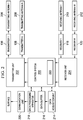
- FIG. 2 is a block diagram of an example of a control system 200 for ranging in multiple wellbores that can implement either partial compensation or full compensation or both.
- the control system 200 can be implemented as a computer system (for example, a desktop computer, a laptop computer, a tablet computer, a personal digital assistant, a smartphone, and the like) that executes computer instructions stored on a computer-readable medium 222 to perform the operations described here.
- the control system 200 can be connected to a transmitter unit 202 and a receiver unit 204.
- Each of the transmitter unit 202 and the receiver unit 204 can be implemented as computer instructions stored on the computer-readable medium 222 and executable in response to instructions from the control system 200.
- the transmitter unit 202 can be connected to the multiple transmitters disposed in the wellbores (for example, the transmitter 106, the transmitter 108).
- the receiver unit 204 can be connected to the multiple receivers disposed in the wellbores (for example, the receiver 114, the receiver 116).
- Each transmitter can be connected to or can include a respective transmitting antenna (for example, a transmitting antenna 206 connected to the transmitter 106, a transmitting antenna 208 connected to the transmitter 108, other transmitting antennas connected to respective transmitters).
- each receiver can be connected to or can include a respective receiving antenna (for example, a receiving antenna 210 connected to the receiver 118, a receiving antenna 212 connected to the receiver 120, other receiving antennas connected to respective receivers).
- the control system 200 can cause the one or more transmitting antennas to produce EM excitation signals in the surrounding formations, for example, using the transmitter unit 202.
- the control system 200 can cause the one or more receiving antennas to receive the EM excitation signals produced by the multiple transmitting antennas, for example, using the receiver unit 204.
- the EM signals received by the receiving antennas are affected by properties of the formation in which the transmitters and the receivers are disposed.
- the excitation signals for the transmitting antennas can be single frequency or broad-band.
- receivers can record the time domain signals and compute the associated frequency domain signals via Fourier transform.
- the control system 200 which is connected to the multiple transmitters and the multiple receivers, can receive the multiple signals, each of which is or is a representation of each signal received by each transmitter from each receiver. For example, the control system 200 can receive each signal as a complex voltage.
- the control system 200 can store the multiple signals in a computer-readable storage medium (for example, the computer-readable medium 222).
- the control system 200 can implement partial compensation or full compensation techniques (described below) on the multiple signals resulting in multiple compensated signals.
- the control system 200 can store the multiple compensated signals in the computer-readable storage medium.
- the control system 200 can process the multiple compensated signals to determine a position of the first wellbore (for example, the wellbore 110) relative to the second wellbore (for example, the wellbore 122), and provide the position the position, for example, to a display device (not shown) connected to the control system 200.
- the control system 200 can implement the compensation technique based on EM signals transmitted by at least two transmitters and received by at least two receivers. To do so, from the signals exchanged by the at least two transmitters and the at least two receivers, the control system 200 can determine multiple compensated signals. The control system 200 can determine at least one compensated signal from a first signal received from a first wellbore and a second signal received from a second wellbore. Each of the transmitters and the receivers provides both amplitude and phase measurements. The control system 200 can measure a value of each EM signal, i.e., measure an amplitude and phase of each EM signal, for example, by digitizing the signal. In the example configurations described in FIG.
- the control system 200 can obtain four measurements from the two transmitters disposed in the production wellbore and the two receivers disposed in the injection wellbore - from transmitter 106 to receiver 118, from transmitter 106 to receiver 120, from transmitter 108 to receiver 118, and from transmitter 108 to receiver 128.
- the control system 200 can receive the measurements as complex voltages, each having an amplitude and a phase.
- the control system 200 can obtain an R value, which is a signal ratio. For example, at a first time instant, the control system 200 can determine a first product of a value of a first signal transmitted by the transmitter 106 to receiver 118 (T1R1) and a value of a second signal transmitted by transmitter 108 to receiver 120 (T2R2). At the first time instant, the control system 200 can also determine a second product of a value of a third signal transmitted by the transmitter 106 to receiver 120 (T1R2) and a value of a fourth signal transmitted by the transmitter 108 to receiver 118 (T2R1). The control system 200 can divide the first product by the second product resulting in a first compensated signal.
- the R value which indicates formation properties, changes over time for ranging applications.
- the control system 200 can determine a third product of a value of a fifth signal transmitted by the transmitter 106 and received by the receiver 118 and a value of a sixth signal transmitted by the transmitter 108 and received by the receiver 120.
- the control system 200 can determine a fourth product of a value of a seventh signal transmitted by the transmitter 106 and received by the receiver 120 and a value of an eighth signal transmitted by the transmitter 108 and received by the receiver 118.
- the control system 200 can divide the third product by the fourth product resulting in a second compensated signal. In this manner, the control system 200 can take a difference in time to obtain a time-lapse measurement, for example, between the first time instant and the second time instant.
- the multiple transmitters and the multiple receivers can be stationary.
- either the multiple transmitters or the multiple receivers (or both) can be moved between the first time instant and the second time instant.
- a decision to move the transmitters or receivers (or both) or keep the transmitters or receivers (or both) stationary can depend on a length of the wellbore (for example, the injection wellbore) that has been drilled between the first time instant and the second time instant. For example, if the multiple receivers are affixed to the MWD tool, which is moved as the wellbore is being drilled, then the multiple receivers can move between the first time instant and the second time instant. If an angle (described above) formed by the multiple receivers with a transmitter no longer satisfies the threshold after the MWD tool has moved, then the transmitters can also be moved.
- the receivers and the transmitters can be stationary.
- either one or more of the transmitters or one or more of the receivers (or both) can be mobile during EM signal transmission and reception.
- the control system 200 can receive the multiple signals from multiple first locations of the transmitters and the receivers, and multiple other signals from multiple second locations to which the multiple transmitters and the multiple receivers are moved in the wellbores.
- the control system 200 records the compensated signal as a function of time.
- the control system 200 can implement the compensation technique based on EM signals exchanged between at least one transmitter, at least one receiver, and either a transmitter or a receiver.
- two measurements are possible - from transmitter 172 to receiver 178 (T1R1) and from transmitter 174 to receiver 178 (T2R1).
- two measurements are possible - from transmitter 152 to receiver 156 (T1R1) and from transmitter 152 to receiver 158 (T1R2).
- the control system 200 can receive the EM signals are complex voltages, each having a respective amplitude and a phase.
- the control system 200 can divide a value (i.e., a voltage value) of a first signal transmitted by transmitter 172 to receiver 178 (T1R1) by a value of a second signal transmitted by transmitter 174 to receiver 178 (T2R1).
- a value i.e., a voltage value
- the control system 200 can implement the afore-described partial compensation techniques at a first time instant. At a second time instant, the control system 200 can divide a value of a third signal transmitted by transmitter 172 to receiver 178 by a value of a fourth signal transmitted by transmitter 174 to receiver 178. The control system 200 can divide the third signal by the fourth signal resulting in a second compensated signal.
- V ' is the voltage that is affected by the multiplicative effect on transmitter X (C TX ) and V is the ideal measurement with no effects.
- the control system 200 can divide a first signal transmitted by transmitter 152 to receiver 156 (T1R1) by a value of a second signal transmitted by transmitter 152 to receiver 158 (T1R2).
- T1R1 the control system 200 takes the two term ratio of the signals, multiplicative effects cancel out as shown below:
- the control system 200 can implement the afore-described partial compensation techniques at a first time instant. At a second time instant, the control system 200 can divide a value of a third signal transmitted by transmitter 152 to receiver 156 by a value of a fourth signal transmitted by transmitter 152 to receiver 158. Similarly to full compensation, the received signal, in partial compensation, can be recorded as a function of time, and a difference in time can be taken to obtain a time-lapse measurement.
- S t 1 , t 2 f R t 1 ⁇ f R t 2
- R can be uncompensated, partially compensated or fully compensated depending on the type of compensation technique that the control system 200 implements.
- Another example for the function f is the logarithmic function, which makes S indicate the logarithmic change in the signal levels between the first time instant (i.e., t 1 ) and the second time instant (i.e., t 2 ) .
- Other examples of the function f are also possible.
- the control system 200 can determine a second difference of measurements at three time instants.
- control system 200 can be connected to a data acquisition unit 214 to receive signals received by the control system 200 from the receiver unit 204.
- the signals can be stored in a data buffer 216 connected to the control system 200 and the data acquisition unit 214.
- the processor for example, a data processing apparatus 218, can be implemented as a component of the control system 200 or can reside external to the control system 200 (or both).
- the control system 200 can be connected to a communication unit 220, which can transmit data using either wired or wireless networks (or both).
- the communication unit 220 can be implemented as a telemetry system.
- the compensation technique is implemented as computer operations.
- the compensation technique can be implemented using hardware or firmware.
- the ratios used in the compensation technique can be calculated by hardware by measuring phase difference and attenuation between the receivers instead of (or in addition to) measuring the absolute signals. Additional time-lapse processing can also be applied on the compensated signal.
- the control system 200 can be implemented down hole or at the surface.
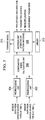
- FIG. 3 is an example of a preprocessing unit for preprocessing electromagnetic signals before partial compensation or full compensation.
- the control system 200 can include multiple components for preprocessing, each of which can be implemented as a computer-readable medium storing instructions executable by the processor (for example, the data processing apparatus 218).
- the control system 200 can implement preprocessing techniques on the multiple signals received from the one or more transmitters before implementing the compensation techniques.
- a first preprocessing unit 304 can receive sensor data from multiple sources (i.e., the transmitters) at time t 1 , i.e., the first time instant.
- a second preprocessing unit 302 can receive sensor data from multiple sources (i.e., the transmitters) at time t 2 , i.e., the second time instant.
- a compensated signal calculation unit 306 can implement resistivity logging signal processing techniques, for example, multi-component synthesis, differential signal synthesis, virtual arrays created from depth/time delayed data, or combinations of them.
- the preprocessing can include filtering with respect to time or depth to improve signal to noise ratio.
- the preprocessing can additionally include multi-array synthesis by combining information from different sensor positions.
- the preprocessing can also include azimuthal binning and multi-bin processing to obtain dipole tensor components as well known in Logging While Drilling propagation induction resistivity well logging.
- Preprocessing can also include calibration operation utilizing past measurements or predicted position (or both) of moving sensor system or environmental conditions.
- control system 200 can implement an inversion unit 308 based on the compensated signal via forward modeling (for example, that uses a forward model 310) and feedback (for example, that uses a library 312).
- the inversion units accept the compensated signals as the input and outputs pipe or environmental parameters such as pipe distance and direction, transmitter location, receiver location, environmental parameters, and the like. Based on the difference between input signals and the modeling result, variable set of output parameters can be adjusted to reduce the difference.
- the afore-described operations can be iterated and stopped once the difference reduces satisfies a threshold.
- a look-up table that maps the input to output parameters can be computed and used. Parameters including pipe distance and direction, transmitter location, wellbore size, and other environmental parameters can be obtained by implementing preprocessing.
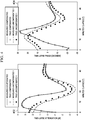
- FIGS. 4A and 4B are plots comparing compensated and uncompensated electromagnetic signals.
- the electromagnetic signals received by the receivers are used to determine the distance between the two wellbores in which the transmitters and the receivers are disposed.
- a high signal can indicate that the wells are close and a low signal can indicate that the wells are far apart.
- time-lapse signal measurement a high signal can indicate that the wells are getting closer and a low signal can indicate that the separation between the wells is increasing.
- the inversion process described above can be the basis on which the interpretation of closeness from the compensated signals is made.
- the plots shown in FIGS. 4A and 4B are determined by ranging in the SAGD application.
- Plot 402 is a plot of time-lapsed attenuation versus time for measured compensated signals, true compensated signals, measured uncompensated signals, and true uncompensated signals.
- Plot 404 is a plot of time-lapse phase versus time for measured compensated signals, true compensated signals, measured uncompensated signals, and true uncompensated signals.
- the produced signal is used to determine the position of the receivers or equivalently the tool body with respect to a reference such as a location in the injector or producer wells, or a previously known position of the receiver.
- the transmitter could alternatively or in addition be moving.
- an amplitude drift and phase draft is used on all of the receivers. The plots show that, despite the draft, the compensated measurement is not affected from phase shifts whereas uncompensated measurements are affected.
- FIG. 5 is a flowchart of an example process 500 for ranging from multiple wellbores implementing full compensation.
- the process 500 can be implemented as computer instructions stored on computer-readable media (for example, the computer-readable medium 222) and executable by the processor (for example, data processing apparatus 218).
- the process 500 can be implemented by the control system 200.
- multiple signals are received. Each signal corresponds to an electromagnetic signal received by a receiver of multiple receivers corresponds to an electromagnetic signal received by a receiver of multiple receivers disposed in multiple wellbores from a transmitter of multiple transmitters disposed in the multiple wellbores.
- full compensation techniques are implemented on the multiple signals resulting in multiple compensated signals. For example, from the received multiple signals, multiple compensated signals can be determined. At least one compensated signal can be determined from a first signal received from a first wellbore and a second signal received from a second wellbore of the plurality of wellbores. At 506, the multiple compensated signals are processed to determine a position of a first wellbore of the multiple wellbores relative to a second wellbore of the multiple wellbores. At 508, the position of the first wellbore relative to the second wellbore is provided.
- FIG. 6 is a flowchart of an example process 600 for ranging from multiple wellbores implementing partial compensation.
- the process 600 can be implemented as computer instructions stored on computer-readable media (for example, the computer-readable medium 222) and executable by the processor (for example, the data processing apparatus 218).
- the process 500 can be implemented by the control system 200.
- multiple signals are received. Each signal corresponds to an electromagnetic signal exchanged by a first transmitter disposed in a first wellbore to transmit electromagnetic signals, a first receiver disposed in a second wellbore to receive the electromagnetic signals transmitted by the first transmitter, and either a second transmitter or a second receiver.
- the second transmitter or the second receiver can be disposed in either the first wellbore or in the second wellbore or in a location other than the wellbore (for example, at the surface).
- partial compensation techniques are implemented on the multiple signals resulting in multiple compensated signals.
- the multiple compensated signals are processed to determine a position of a first wellbore of the multiple wellbores relative to a second wellbore of the multiple wellbores.
- the position of the first wellbore relative to the second wellbore is provided.
Landscapes
- Engineering & Computer Science (AREA)
- Life Sciences & Earth Sciences (AREA)
- Geology (AREA)
- Physics & Mathematics (AREA)
- Mining & Mineral Resources (AREA)
- General Life Sciences & Earth Sciences (AREA)
- Environmental & Geological Engineering (AREA)
- Geochemistry & Mineralogy (AREA)
- Fluid Mechanics (AREA)
- Geophysics (AREA)
- Remote Sensing (AREA)
- Electromagnetism (AREA)
- General Physics & Mathematics (AREA)
- Radar Systems Or Details Thereof (AREA)
- Geophysics And Detection Of Objects (AREA)
- Arrangements For Transmission Of Measured Signals (AREA)
- Measurement Of Levels Of Liquids Or Fluent Solid Materials (AREA)
Description
- The present disclosure relates to software, computer systems, and computer-implemented media used in forming wellbores in subsurface formations containing hydrocarbons.
- Wellbores formed in subterranean hydrocarbon reservoirs enable recovery of a portion of the hydrocarbons using production techniques. The hydrocarbons can adhere to the reservoirs, for example, due to a combination of capillary forces, adhesive forces, cohesive forces, and hydraulic forces. Steam-assisted gravity drainage (SAGD) is an example of an enhanced hydrocarbon recovery technique in which heated treatment fluids (for example, steam) can be applied to the formation to facilitate and enhance recovery of the hydrocarbons that are adhered to the formation. In an implementation of the SAGD technique, an injection wellbore can be formed adjacent to a production wellbore, and the heated treatment fluids can be injected through the injection wellbore into the formation surrounding the production wellbore. The heated fluids can decrease an adherence of the hydrocarbons to the formation, thereby releasing the hydrocarbons into the production wellbore.
- While forming (for example, drilling) the injection wellbore, knowledge of a location of the production wellbore relative to the injection wellbore can be important. Ranging is an example of a method to control a position of a wellbore being drilled relative to an existing wellbore. In ranging, an electromagnetic source located in the existing wellbore provides electromagnetic signals received by sensors in the wellbore being drilled. In another example of ranging, both the electromagnetic source and the sensors can be located in the wellbore being drilled. Several conditions, for example, wellbore drilling conditions, can adversely affect an ability of the electromagnetic source or the sensors (or both) to exchange the electromagnetic signals, and, consequently, affect ranging in the wellbores.
- Documents cited during prosecution include
WO 2012/067611 A1 , which discloses an apparatus and method for drilling a well;WO 2009/128989 A1 , which discloses a method for drilling a wells in close relationship using magnetic ranging while drilling;US 2002/0000808 A1 , which discloses a permanently emplaced electromagnetic system and a method of measuring formation resistivity adjacent to and between wells; andUS 2008/0041626 A1 , which discloses magnetic ranging while drilling parallel wells. - According to a first aspect of the present invention, there is provided a system for ranging in wellbores, the system comprising: a plurality of transmitters disposed in a plurality of wellbores, each transmitter configured to transmit electromagnetic signals; a plurality of receivers disposed in the plurality of wellbores, each receiver configured to receive the electromagnetic signals transmitted by the plurality of transmitters; and a processor connected to the plurality of transmitters and the plurality of receivers, the processor configured to: receive a plurality of signals from the plurality of receivers as sent by the plurality of transmitters, from the received plurality of signals, determine a plurality of compensated signals, at least one compensated signal determined from a first signal received from a first wellbore of the plurality of wellbores and a second signal received from a second wellbore of the plurality of wellbores, process the plurality of compensated signals to determine a position of the first wellbore of the plurality of wellbores relative to the second wellbore of the plurality of wellbores, and provide the position of the first wellbore relative to the second wellbore, wherein, to determine the plurality of compensated signals, the processor is configured, at a first time instant, to: determine a first product of a value of a first signal transmitted by a first transmitter and received by a first receiver, and a value of a second signal transmitted by a second transmitter and received by a second receiver; determine a second product of a value of a third signal transmitted by the first transmitter and received by the second receiver, and a value of a fourth signal transmitted by the second transmitter and received by the first receiver; and divide the first product by the second product resulting in a first compensated signal.
- According to a second aspect of the present invention, there is provided a computer-readable medium storing instructions executable by a processor to perform operations for ranging in wellbores, the operations comprising: receiving a plurality of signals from a plurality of transmitters disposed in a plurality of wellbores to transmit electromagnetic signals and a plurality of receivers disposed in the plurality of wellbores to receive the electromagnetic signals transmitted by the plurality of transmitters, wherein each signal of the plurality of signals is received by each transmitter from each receiver, from the received plurality of signals, determining a plurality of compensated signals, at least one compensated signal determined from a first signal received from a first wellbore of the plurality of wellbores and a second signal received from a second wellbore of the plurality of wellbores, processing the plurality of compensated signals to determine a position of a first wellbore of the plurality of wellbores relative to a second wellbore of the plurality of wellbores, and providing the position of the first wellbore relative to the second wellbore, wherein, determining a plurality of compensated signals comprises: determining, at a first time instant, a first product of a first signal transmitted by a first transmitter and received by a first receiver and a value of a second signal transmitted by a second transmitter and received by a second receiver; determining a second product of a value of a third signal transmitted by the first transmitter and received by the second receiver, and a value of a fourth signal transmitted by the second transmitter and received by the first receiver; and dividing the first product by the second product to result in a compensated signal.
- According to a third aspect of the present invention, there is provided a method for ranging in wellbores, the method comprising: receiving, by a processor, a plurality of signals from a plurality of transmitters disposed in a plurality of wellbores to transmit electromagnetic signals and a plurality of receivers disposed in the plurality of wellbores to receive the electromagnetic signals transmitted by the plurality of transmitters, wherein each signal of the plurality of signals is received by each transmitter from each receiver, from the received plurality of signals, determining, by the processor, a plurality of compensated signals, at least one compensated signal determined from a first signal received from a first wellbore of the plurality of wellbores and a second signal received from a second wellbore of the plurality of wellbores, processing, by the processor, the plurality of compensated signals to determine a position of a first wellbore of the plurality of wellbores relative to a second wellbore of the plurality of wellbores, and providing, by the processor, the position of the first wellbore relative to the second wellbore, wherein determining a plurality of compensated signals comprises: determining, at a first time instant, a first product of a first signal transmitted by a first transmitter and received by a first receiver and a value of a second signal transmitted by a second transmitter and received by a second receiver; determining a second product of a value of a third signal transmitted by the first transmitter and received by the second receiver, and a value of a fourth signal transmitted by the second transmitter and received by the first receiver; and dividing the first product by the second product to result in a compensated signal.
- In order to better understand the present invention, and to show how the same may be carried into effect, reference will now be made, by way of example only, to the accompanying drawings.
-
FIGS. 1A-1D are schematic, elevation views illustrating examples of multiple wellbores for ranging. -
FIG. 2 is a block diagram of an example of a system for ranging in multiple wellbores. -
FIG. 3 is an example operational chart that shows relationships between processing, compensation, and inversion units. -
FIGS. 4A and 4B are plots comparing compensated and uncompensated electromagnetic signals. -
FIG. 5 is a flowchart of an example process for ranging from multiple wellbores implementing full compensation. -
FIG. 6 is a flowchart of an example process for ranging from multiple wellbores implementing partial compensation. - Like reference symbols in the various drawings indicate like elements.
- This disclosure relates to computer-implemented methods, computer systems, and computer-readable media for downhole ranging from multiple wellbores using compensated electromagnetic measurements. In the example of an SAGD application, precise ranging of the steam injection wellbore can be important. If the injection wellbore intersects the production wellbore, a blowout can result from the pressure difference between the wells. If the steam injection wellbore is too far from the production wellbore, the steam injection may not result in significant increased recovery. The ranging process described here can be used to determine the distance and precise location while drilling the injection wellbore.
- Ranging focuses on changes in the positions of electromagnetic transmitters and receivers to provide precise measurements. The transmitters and receivers are disposed in wellbores for ranging. For example, the transmitters can be placed in a production wellbore and receivers in a wellbore that is being drilled (for example, for steam injection). The strength of the transmitters and receivers may not precisely be known. There can be a degree of variability associated with differences in manufacturing, differences in electronics, temperature changes, or combinations of them. In addition, an electromagnetic signal may experience changes, for example, in an approaching target well. Compensation is a technique that can be used to eliminate or minimize such effects that can adversely affect measurement of the electromagnetic signals. For example, compensation can eliminate or minimize the effects of elements (for example, manufacturing differences, electronic differences, temperature changes, and the like) to ensure that the remaining changes observed and measured are relevant to the ranging application.
- As described below, one or both of two types of compensation - namely, partial compensation and full compensation - can be applied to ranging from multiple wellbores used, for example, in enhanced hydrocarbon recovery. In full compensation implementations, for example, multiple electromagnetic signal transmitters and multiple electromagnetic receivers can be located in a production wellbore and an injection wellbore, respectively. In partial compensation implementations, for example, one electromagnetic signal transmitter and two electromagnetic sensors or two electromagnetic signal transmitters and one electromagnetic sensor can be located in a production wellbore and an injection wellbore, respectively. The production wellbore can be an existing wellbore; the injection wellbore can be one that is being drilled adjacent the production wellbore for steam injection. A computer system described below can implement either or both compensation techniques when interpreting changes in electromagnetic signals between the one or more transmitters and the one or more receivers to eliminate or minimize some or all of the adverse effects described above. For example, by implementing the partial or full compensation technique, the computer system can eliminate or minimize confounding effects of any type of amplitude or phase shift that can be attributable to electronic drift, drift as a result of temperature change, or unknown phase or amplitude. After the computer system implements the partial or full compensation technique (or both), the computer system can use changes observed in the electromagnetic signal as the basis for measurements for use in ranging the injection wellbore.
- Implementing partial or full compensation techniques (or both) on the electromagnetic signals prior to ranging can decrease a reliance on other correction or calibration techniques that are either complicated or impose strict requirements on electronics. Relative to the other correction/calibration techniques, the compensation technique can ease requirements on electronics and result in simpler and more robust measurements. The compensation techniques described below can provide extended coverage in the area of ranging. The measurements can be more accurate and robust than conventional compensation techniques. The compensation techniques can also provide more design flexibility in electronics or mechanics (or both) implemented in enhanced hydrocarbon recovery techniques, such as SAGD. The compensation can correct for the effect of temperature, fatigue or corrosion on sensor electronics such as amplitude or phase drifts. The compensation can also allow easier deployment of sensors since no in-situ calibration is required.
-
FIGS. 1A and 1B are schematic, elevation views illustrating examples of multiple wellbores for ranging implementing full compensation. In some implementations, multiple transmitters (for example, afirst transmitter 102, a second transmitter 104) can be disposed in multiple wellbores (for example, afirst wellbore 110, a second wellbore 122). Each transmitter (i.e., thefirst transmitter 102, the second transmitter 104) can transmit electromagnetic signals. Multiple receivers (for example, afirst receiver 114, a second receiver 116) can be disposed in the multiple wellbores. Each receiver (i.e., thefirst receiver 114, the second wellbore 116) can receive electromagnetic signals transmitted by the multiple transmitters. For example, thefirst transmitter 102 and thesecond transmitter 104 can be disposed in apre-existing production wellbore 110, and can be spaced apart by a distance ranging between 0.6 m (2 feet) and 15 m (50 feet). Thefirst receiver 114 and thesecond receiver 116 can be disposed in an SAGDwellbore 122 being drilled, and can be spaced apart by a distance ranging between 0.6 m (2 feet) and 15 m (50 feet). In sum, at least two transmitters and at least two receivers can be disposed in at least two wellbores to implement full compensation. - In some implementations, the
first receiver 114 and thesecond receiver 116 can be affixed to a Measuring While Drilling (MWD)tool 126 disposed in theSAGD wellbore 122. Alternatively, or in addition, the sensors can be affixed to a production logging tool, outside the casings on special housings, inside the casing to transmit or receive from the formation, in open-hole sections in the wells, or in combinations of them. The sensors can alternatively or in addition be placed on a production tool inside the casing. A casing can be all or portions of one or more casing strings disposed in the wellbore. -
FIGS. 1C and 1D are schematic, elevation views illustrating examples of multiple wellbores for ranging implementing partial compensation. In some implementations, afirst transmitter 152 can be disposed in a first wellbore 154 (for example, a pre-existing production wellbore) to transmit electromagnetic signals. Afirst receiver 156 can be disposed in a second wellbore 180 (for example, an SAGD wellbore) to receive the electromagnetic signals transmitted by the first transmitter. Either a second transmitter or a second receiver can be disposed in either the first wellbore or the second wellbore to exchange electromagnetic signals with the first transmitter and the first receiver. For example, as shown inFIG. 1C , thefirst receiver 156 and asecond receiver 158 can be disposed on anMWD tool 162 in the second wellbore 160. In another example, as shown in FIG. ID, afirst transmitter 172 and a second transmitter 174 can be disposed in a pre-existing production wellbore 176 to exchange electromagnetic signals with areceiver 178 disposed on aproduction logging tool 182 disposed in anSAGD wellbore 180. In sum, at least a first transmitter, at least a first receiver, and either a second transmitter or a second receiver can be disposed in at least two wellbores to implement partial compensation. - The configuration of the first wellbore relative to the second wellbore (for example, the arrangement of the
wellbore 110 relative to thewellbore 122, the arrangement of thewellbore 112 relative to thewellbore 124, the arrangement of thewellbore 154 relative to the wellbore 160, or the arrangement of thewellbore 176 relative to the wellbore 180), and the arrangement of transmitters and receivers in the first wellbore and the second wellbore are exemplary. Several other configurations are possible. For example, in both partial and full compensation implementations, more than two transmitters and more than two receivers can be disposed in thesecond wellbore 122 and thefirst wellbore 110, respectively. In this case, compensation may be performed in fours. A transmitter and a receiver can be disposed in the same wellbore in both partial and full compensation implementations. The first wellbore is substantially perpendicular to the second wellbore , for example, in the formation 140 (FIG. 1A ) or in the formation 166 (FIG. 1C ). Alternatively, as shown in the formation 150 (FIG. 1B ) or in the formation 184 (FIG. ID), a third wellbore can be substantially parallel to a fourth wellbore. - One of the two wellbores can be a production wellbore in which one or more transmitters are disposed. The other wellbore can be an injection wellbore in which a tool (for example, an MWD tool 128) is disposed. In a full compensation implementation, multiple receivers (for example, a
third receiver 118 and a fourth receiver 120) can be disposed in thefourth wellbore 124, for example, affixed to theMWD tool 128. In a partial compensation implementation, onetransmitter 178 can be affixed to a tool (for example, the production logging tool 182) in thewellbore 180. In some implementations, the wellbores formed in the formation can be at any angle to each other instead of being either substantially parallel or substantially perpendicular. Transmitters and receivers can be interchangeably disposed in any wellbore. In sum, the techniques described here can be implemented in ranging wellbores of any configuration by disposing the sensors (i.e., the transmitters and the receivers) in any of the two wellbores. - In some full compensation implementations, the
first transmitter 102, thefirst receiver 114 and thesecond receiver 116 can be disposed in thefirst wellbore 110 and the second wellbore 122 (FIG. 1A ) such that an angle formed by a first line connecting thefirst receiver 114 and thefirst transmitter 102 and a second line connecting thesecond receiver 116 and thefirst transmitter 106 satisfies a threshold angle, which, in some implementations, can be at least 5 degrees. Similarly, thethird transmitter 106, thethird receiver 118 and thefourth receiver 120 can be disposed in thethird wellbore 112 and thefourth wellbore 124 such that an angle formed by a line connecting thethird receiver 118 and thethird transmitter 106, and a line connecting thefourth receiver 120 and thethird transmitter 106 satisfies the threshold angle. In some implementations, the positions of the transmitters and the receivers in the multiple wellbores can be periodically changed, for example, as one of the wellbores is being formed relative to the other existing wellbore, such that the angle described above is maintained to satisfy the threshold angle. The sensitive volume of the sensing system can include a trapezoidal shape that is formed by connecting the two transmitters and the two receivers in each case. To increase the coverage, more than two transmitters and more than two receivers may be used. -
FIG. 2 is a block diagram of an example of acontrol system 200 for ranging in multiple wellbores that can implement either partial compensation or full compensation or both. Thecontrol system 200 can be implemented as a computer system (for example, a desktop computer, a laptop computer, a tablet computer, a personal digital assistant, a smartphone, and the like) that executes computer instructions stored on a computer-readable medium 222 to perform the operations described here. Thecontrol system 200 can be connected to atransmitter unit 202 and areceiver unit 204. Each of thetransmitter unit 202 and thereceiver unit 204 can be implemented as computer instructions stored on the computer-readable medium 222 and executable in response to instructions from thecontrol system 200. Thetransmitter unit 202 can be connected to the multiple transmitters disposed in the wellbores (for example, thetransmitter 106, the transmitter 108). Thereceiver unit 204 can be connected to the multiple receivers disposed in the wellbores (for example, thereceiver 114, the receiver 116). - Each transmitter can be connected to or can include a respective transmitting antenna (for example, a transmitting
antenna 206 connected to thetransmitter 106, a transmittingantenna 208 connected to thetransmitter 108, other transmitting antennas connected to respective transmitters). Similarly, each receiver can be connected to or can include a respective receiving antenna (for example, a receivingantenna 210 connected to thereceiver 118, a receivingantenna 212 connected to thereceiver 120, other receiving antennas connected to respective receivers). In some implementations (including the partial compensation and full compensation implementations), thecontrol system 200 can cause the one or more transmitting antennas to produce EM excitation signals in the surrounding formations, for example, using thetransmitter unit 202. Thecontrol system 200 can cause the one or more receiving antennas to receive the EM excitation signals produced by the multiple transmitting antennas, for example, using thereceiver unit 204. The EM signals received by the receiving antennas are affected by properties of the formation in which the transmitters and the receivers are disposed. The excitation signals for the transmitting antennas can be single frequency or broad-band. For broad-band excitations, receivers can record the time domain signals and compute the associated frequency domain signals via Fourier transform. - The
control system 200, which is connected to the multiple transmitters and the multiple receivers, can receive the multiple signals, each of which is or is a representation of each signal received by each transmitter from each receiver. For example, thecontrol system 200 can receive each signal as a complex voltage. Thecontrol system 200 can store the multiple signals in a computer-readable storage medium (for example, the computer-readable medium 222). Thecontrol system 200 can implement partial compensation or full compensation techniques (described below) on the multiple signals resulting in multiple compensated signals. Thecontrol system 200 can store the multiple compensated signals in the computer-readable storage medium. Thecontrol system 200 can process the multiple compensated signals to determine a position of the first wellbore (for example, the wellbore 110) relative to the second wellbore (for example, the wellbore 122), and provide the position the position, for example, to a display device (not shown) connected to thecontrol system 200. - In full compensation implementations, the
control system 200 can implement the compensation technique based on EM signals transmitted by at least two transmitters and received by at least two receivers. To do so, from the signals exchanged by the at least two transmitters and the at least two receivers, thecontrol system 200 can determine multiple compensated signals. Thecontrol system 200 can determine at least one compensated signal from a first signal received from a first wellbore and a second signal received from a second wellbore. Each of the transmitters and the receivers provides both amplitude and phase measurements. Thecontrol system 200 can measure a value of each EM signal, i.e., measure an amplitude and phase of each EM signal, for example, by digitizing the signal. In the example configurations described inFIG. 1B , thecontrol system 200 can obtain four measurements from the two transmitters disposed in the production wellbore and the two receivers disposed in the injection wellbore - fromtransmitter 106 toreceiver 118, fromtransmitter 106 toreceiver 120, fromtransmitter 108 toreceiver 118, and fromtransmitter 108 toreceiver 128. Thecontrol system 200 can receive the measurements as complex voltages, each having an amplitude and a phase. - From these measurements, the
control system 200 can obtain an R value, which is a signal ratio. For example, at a first time instant, thecontrol system 200 can determine a first product of a value of a first signal transmitted by thetransmitter 106 to receiver 118 (T1R1) and a value of a second signal transmitted bytransmitter 108 to receiver 120 (T2R2). At the first time instant, thecontrol system 200 can also determine a second product of a value of a third signal transmitted by thetransmitter 106 to receiver 120 (T1R2) and a value of a fourth signal transmitted by thetransmitter 108 to receiver 118 (T2R1). Thecontrol system 200 can divide the first product by the second product resulting in a first compensated signal. The R value, which indicates formation properties, changes over time for ranging applications. - A compensated signal has the capability of cancelling any multiplicative effects for transmitters or receivers in the form

control system 200 determines the four term ratio of the signals as described above, multiplicative effects cancel out as shown below:
- Similarly, to operations performed at the first time instant, at a second time instant, the
control system 200 can determine a third product of a value of a fifth signal transmitted by thetransmitter 106 and received by thereceiver 118 and a value of a sixth signal transmitted by thetransmitter 108 and received by thereceiver 120. At the second time instant, thecontrol system 200 can determine a fourth product of a value of a seventh signal transmitted by thetransmitter 106 and received by thereceiver 120 and a value of an eighth signal transmitted by thetransmitter 108 and received by thereceiver 118. Thecontrol system 200 can divide the third product by the fourth product resulting in a second compensated signal. In this manner, thecontrol system 200 can take a difference in time to obtain a time-lapse measurement, for example, between the first time instant and the second time instant. - Between the first time instant and the second time instant, the multiple transmitters and the multiple receivers can be stationary. Alternatively, either the multiple transmitters or the multiple receivers (or both) can be moved between the first time instant and the second time instant. A decision to move the transmitters or receivers (or both) or keep the transmitters or receivers (or both) stationary can depend on a length of the wellbore (for example, the injection wellbore) that has been drilled between the first time instant and the second time instant. For example, if the multiple receivers are affixed to the MWD tool, which is moved as the wellbore is being drilled, then the multiple receivers can move between the first time instant and the second time instant. If an angle (described above) formed by the multiple receivers with a transmitter no longer satisfies the threshold after the MWD tool has moved, then the transmitters can also be moved.
- In some implementations, at the instant that the
control system 200 causes the transmitters to transmit the EM signals and the receivers to receive the EM signals, the receivers and the transmitters can be stationary. Alternatively, either one or more of the transmitters or one or more of the receivers (or both) can be mobile during EM signal transmission and reception. In this manner, thecontrol system 200 can receive the multiple signals from multiple first locations of the transmitters and the receivers, and multiple other signals from multiple second locations to which the multiple transmitters and the multiple receivers are moved in the wellbores. - The
control system 200 records the compensated signal as a function of time. In general, a function f can be used before the subtraction as shown below:

- In partial compensation implementations, the
control system 200 can implement the compensation technique based on EM signals exchanged between at least one transmitter, at least one receiver, and either a transmitter or a receiver. In implementations with two transmitters and a receiver, two measurements are possible - fromtransmitter 172 to receiver 178 (T1R1) and from transmitter 174 to receiver 178 (T2R1). In implementations with two receivers and a transmitter, two measurements are possible - fromtransmitter 152 to receiver 156 (T1R1) and fromtransmitter 152 to receiver 158 (T1R2). Thecontrol system 200 can receive the EM signals are complex voltages, each having a respective amplitude and a phase. In the example with two transmitters and one receiver, to determine an R (ratio) value, thecontrol system 200 can divide a value (i.e., a voltage value) of a first signal transmitted bytransmitter 172 to receiver 178 (T1R1) by a value of a second signal transmitted by transmitter 174 to receiver 178 (T2R1). When thecontrol system 200 takes the two term ratio of the signals, multiplicative effects cancel out as shown below, resulting in a first compensated signal:
- The
control system 200 can implement the afore-described partial compensation techniques at a first time instant. At a second time instant, thecontrol system 200 can divide a value of a third signal transmitted bytransmitter 172 toreceiver 178 by a value of a fourth signal transmitted by transmitter 174 toreceiver 178. Thecontrol system 200 can divide the third signal by the fourth signal resulting in a second compensated signal. The R value, which indicates formation properties, changes over time for ranging applications. Partially compensated signal has the capability of canceling any multiplicative effects for either transmitters in the following form:
- In the equation above, V' is the voltage that is affected by the multiplicative effect on transmitter X (CTX) and V is the ideal measurement with no effects.
- Similarly, in the example with two receivers and one transmitter, to determine an R (ratio) value, the
control system 200 can divide a first signal transmitted bytransmitter 152 to receiver 156 (T1R1) by a value of a second signal transmitted bytransmitter 152 to receiver 158 (T1R2). When thecontrol system 200 takes the two term ratio of the signals, multiplicative effects cancel out as shown below:
- The
control system 200 can implement the afore-described partial compensation techniques at a first time instant. At a second time instant, thecontrol system 200 can divide a value of a third signal transmitted bytransmitter 152 toreceiver 156 by a value of a fourth signal transmitted bytransmitter 152 toreceiver 158. Similarly to full compensation, the received signal, in partial compensation, can be recorded as a function of time, and a difference in time can be taken to obtain a time-lapse measurement.
- In this equation, R can be uncompensated, partially compensated or fully compensated depending on the type of compensation technique that the
control system 200 implements. One example of the function f is the identity function, i.e., f(x) = x. Another example for the function f is the logarithmic function, which makes S indicate the logarithmic change in the signal levels between the first time instant (i.e., t1 ) and the second time instant (i.e., t2 ). Other examples of the function f are also possible. Further, in some implementations, thecontrol system 200 can determine a second difference of measurements at three time instants. - In some implementations, the
control system 200 can be connected to adata acquisition unit 214 to receive signals received by thecontrol system 200 from thereceiver unit 204. As an alternative or in addition to storing the signals in the computer-readable medium 222, the signals can be stored in adata buffer 216 connected to thecontrol system 200 and thedata acquisition unit 214. The processor (for example, a data processing apparatus 218) can be implemented as a component of thecontrol system 200 or can reside external to the control system 200 (or both). To provide the position of the first wellbore relative to the second wellbore, for example, to a display device at the surface, thecontrol system 200 can be connected to acommunication unit 220, which can transmit data using either wired or wireless networks (or both). For example, thecommunication unit 220 can be implemented as a telemetry system. - In the example operations described with reference to the
control system 200, the compensation technique is implemented as computer operations. Alternatively or in addition, the compensation technique can be implemented using hardware or firmware. For example, the ratios used in the compensation technique can be calculated by hardware by measuring phase difference and attenuation between the receivers instead of (or in addition to) measuring the absolute signals. Additional time-lapse processing can also be applied on the compensated signal. Thecontrol system 200 can be implemented down hole or at the surface. -
FIG. 3 is an example of a preprocessing unit for preprocessing electromagnetic signals before partial compensation or full compensation. As shown inFIG. 3 , thecontrol system 200 can include multiple components for preprocessing, each of which can be implemented as a computer-readable medium storing instructions executable by the processor (for example, the data processing apparatus 218). In some implementations, thecontrol system 200 can implement preprocessing techniques on the multiple signals received from the one or more transmitters before implementing the compensation techniques. For example, afirst preprocessing unit 304 can receive sensor data from multiple sources (i.e., the transmitters) at time t1 , i.e., the first time instant. Asecond preprocessing unit 302 can receive sensor data from multiple sources (i.e., the transmitters) at time t2 , i.e., the second time instant. In some implementations, a compensatedsignal calculation unit 306 can implement resistivity logging signal processing techniques, for example, multi-component synthesis, differential signal synthesis, virtual arrays created from depth/time delayed data, or combinations of them. The preprocessing can include filtering with respect to time or depth to improve signal to noise ratio. The preprocessing can additionally include multi-array synthesis by combining information from different sensor positions. The preprocessing can also include azimuthal binning and multi-bin processing to obtain dipole tensor components as well known in Logging While Drilling propagation induction resistivity well logging. Preprocessing can also include calibration operation utilizing past measurements or predicted position (or both) of moving sensor system or environmental conditions. - Alternatively, or in addition, the
control system 200 can implement aninversion unit 308 based on the compensated signal via forward modeling (for example, that uses a forward model 310) and feedback (for example, that uses a library 312). The inversion units accept the compensated signals as the input and outputs pipe or environmental parameters such as pipe distance and direction, transmitter location, receiver location, environmental parameters, and the like. Based on the difference between input signals and the modeling result, variable set of output parameters can be adjusted to reduce the difference. The afore-described operations can be iterated and stopped once the difference reduces satisfies a threshold. Alternatively, or in addition, a look-up table that maps the input to output parameters can be computed and used. Parameters including pipe distance and direction, transmitter location, wellbore size, and other environmental parameters can be obtained by implementing preprocessing. -
FIGS. 4A and 4B are plots comparing compensated and uncompensated electromagnetic signals. The electromagnetic signals received by the receivers are used to determine the distance between the two wellbores in which the transmitters and the receivers are disposed. In the case of no time-lapse signal measurement, a high signal can indicate that the wells are close and a low signal can indicate that the wells are far apart. In the case of time-lapse signal measurement, a high signal can indicate that the wells are getting closer and a low signal can indicate that the separation between the wells is increasing. The inversion process described above can be the basis on which the interpretation of closeness from the compensated signals is made. The plots shown inFIGS. 4A and 4B are determined by ranging in the SAGD application.Plot 402 is a plot of time-lapsed attenuation versus time for measured compensated signals, true compensated signals, measured uncompensated signals, and true uncompensated signals. Plot 404 is a plot of time-lapse phase versus time for measured compensated signals, true compensated signals, measured uncompensated signals, and true uncompensated signals. The produced signal is used to determine the position of the receivers or equivalently the tool body with respect to a reference such as a location in the injector or producer wells, or a previously known position of the receiver. Although the receiver is moving in this example, the transmitter could alternatively or in addition be moving. In this example, an amplitude drift and phase draft is used on all of the receivers. The plots show that, despite the draft, the compensated measurement is not affected from phase shifts whereas uncompensated measurements are affected. -
FIG. 5 is a flowchart of anexample process 500 for ranging from multiple wellbores implementing full compensation. Theprocess 500 can be implemented as computer instructions stored on computer-readable media (for example, the computer-readable medium 222) and executable by the processor (for example, data processing apparatus 218). For example, theprocess 500 can be implemented by thecontrol system 200. At 502, multiple signals are received. Each signal corresponds to an electromagnetic signal received by a receiver of multiple receivers corresponds to an electromagnetic signal received by a receiver of multiple receivers disposed in multiple wellbores from a transmitter of multiple transmitters disposed in the multiple wellbores. - At 504, full compensation techniques are implemented on the multiple signals resulting in multiple compensated signals. For example, from the received multiple signals, multiple compensated signals can be determined. At least one compensated signal can be determined from a first signal received from a first wellbore and a second signal received from a second wellbore of the plurality of wellbores. At 506, the multiple compensated signals are processed to determine a position of a first wellbore of the multiple wellbores relative to a second wellbore of the multiple wellbores. At 508, the position of the first wellbore relative to the second wellbore is provided.
-
FIG. 6 is a flowchart of anexample process 600 for ranging from multiple wellbores implementing partial compensation. Theprocess 600 can be implemented as computer instructions stored on computer-readable media (for example, the computer-readable medium 222) and executable by the processor (for example, the data processing apparatus 218). For example, theprocess 500 can be implemented by thecontrol system 200. At 602, multiple signals are received. Each signal corresponds to an electromagnetic signal exchanged by a first transmitter disposed in a first wellbore to transmit electromagnetic signals, a first receiver disposed in a second wellbore to receive the electromagnetic signals transmitted by the first transmitter, and either a second transmitter or a second receiver. The second transmitter or the second receiver can be disposed in either the first wellbore or in the second wellbore or in a location other than the wellbore (for example, at the surface). - At 604, partial compensation techniques are implemented on the multiple signals resulting in multiple compensated signals. At 606, the multiple compensated signals are processed to determine a position of a first wellbore of the multiple wellbores relative to a second wellbore of the multiple wellbores. At 608, the position of the first wellbore relative to the second wellbore is provided.
- A number of embodiments have been described. Nevertheless, it will be understood that various modifications may be made without departing from the scope of the appended claims.
Claims (18)
- A system for ranging in wellbores, the system comprising:a plurality of transmitters (102, 104) disposed in a plurality of wellbores (110, 122), each transmitter configured to transmit electromagnetic signals;a plurality of receivers (114, 116) disposed in the plurality of wellbores (110, 122), each receiver configured to receive the electromagnetic signals transmitted by the plurality of transmitters (102, 104); anda processor connected to the plurality of transmitters (102, 104) and the plurality of receivers (114, 116), the processor configured to:receive a plurality of signals from the plurality of receivers (114, 116) as sent by the plurality of transmitters (102, 104),from the received plurality of signals, determine a plurality of compensated signals, at least one compensated signal determined from a first signal received from a first wellbore (110) of the plurality of wellbores (110, 122) and a second signal received from a second wellbore (122) of the plurality of wellbores (110, 122),process the plurality of compensated signals to determine a position of the first wellbore (110) of the plurality of wellbores relative to the second wellbore (122) of the plurality of wellbores, andprovide the position of the first wellbore (110) relative to the second wellbore (122), wherein, to determine the plurality of compensated signals, the processor is configured, at a first time instant, to:determine a first product of a value of a first signal transmitted by a first transmitter and received by a first receiver, and a value of a second signal transmitted by a second transmitter and received by a second receiver;determine a second product of a value of a third signal transmitted by the first transmitter and received by the second receiver, and a value of a fourth signal transmitted by the second transmitter and received by the first receiver; anddivide the first product by the second product resulting in a first compensated signal.
- The system of claim 1, wherein the first wellbore (110) is a pre-existing production wellbore, and wherein either the plurality of receivers (114, 116) or the plurality of transmitters (102, 104) or a combination of at least one receiver and at least one transmitter are disposed in the production wellbore (110).
- The system of claim 2, wherein either the plurality of receivers (114, 116) or the plurality of transmitters (102, 104) or a combination of at least one receiver and at least one transmitter are spaced apart and affixed to one or more portions of casings disposed within the production wellbore (110).
- The system of claim 1 or 2, wherein the second wellbore (122) is a steam-assisted gravity drainage (SAGD) wellbore being drilled, and wherein either the plurality of receivers (114, 116) or the plurality of transmitters (102, 104) or a combination of at least one receiver and at least one transmitter are disposed in the SAGD wellbore.
- The system of claim 4, wherein the system further comprises a measurement while drilling (MWD) tool disposed in the SAGD wellbore (122), wherein either the plurality of receivers (114, 116) or the plurality of transmitters (102, 104) or a combination of at least one receiver and at least one transmitter are affixed to the MWD tool.
- The system of claim 4 or 5, wherein either the plurality of receivers (114, 116) or the plurality of transmitters (102, 104) or a combination of at least one receiver and at least one transmitter are spaced apart by a distance ranging between 0.6 m (2 feet) and 15 m (50 feet).
- The system of any preceding claim, wherein the first wellbore (110) and the second wellbore (122) are either substantially parallel to each other or substantially perpendicular to each other.
- The system of claim 7, wherein the plurality of transmitters includes a first transmitter and the plurality of receivers includes a first receiver and a second receiver, and wherein the first transmitter, the first receiver and the second receiver are disposed in the plurality of wellbores (110, 122) such that an angle formed by a first line connecting the first receiver and the first transmitter and a second line connecting the second receiver and the first transmitter satisfies a threshold angle, and, optionally, wherein the threshold angle is at least 5 degrees.
- The system of claim 7 or 8, wherein the processor is further configured to measure a value of each of the plurality of signals as a complex voltage.
- The system of claim 7, 8 or 9, wherein the processor is further configured to receive the plurality of signals from a first plurality of locations of the plurality of transmitters (102, 104) and the plurality of receivers (114, 116) in the plurality of wellbores, and receive another plurality of signals from a second plurality of locations to which the plurality of transmitters (102, 104) and the plurality of receivers (114, 116) are moved in the plurality of wellbores.
- The system of claim 7, 8, 9 or 10, wherein the system further comprises a computer-readable storage medium to store the plurality of signals and the plurality of compensated signals.
- The system of any one of claims 7 to 11, wherein the processor is further configured to implement preprocessing techniques on the plurality of signals before determining the plurality of compensated signals.
- The system of claim 1, wherein the processor is further configured, at a second time instant, to:determine a third product of a value of a fifth signal transmitted by the first transmitter and received by the first receiver, and a value of a sixth signal transmitted by the second transmitter and received by the second receiver;determine a fourth product of a value of a seventh signal transmitted by the first transmitter and received by the second receiver, and a value of an eighth signal transmitted by the second transmitter and received by the first receiver; anddivide the third product by the fourth product resulting in a second compensated signal.
- The system of claim 13, wherein the processor is further configured to:record the first compensated signal and the second compensated signal as a first function of time and a second function of time, respectively; andobtain a time-lapse measurement between the first instant and the second instant.
- The system of claim 14, wherein, to obtain the time-lapse measurement between the first instant and the second instant, the processor is configured to:apply a logarithmic function to the first function of time;apply a logarithmic function to the second function of time; anddetermine a difference between the logarithmic function applied to the first function of time and the logarithmic function applied to the second function of time.
- The system of claim 13, 14 or 15, wherein the plurality of transmitters (102, 104) and the plurality of receivers (114, 116) are stationary during the first time instant and the second time instant; or
wherein either the plurality of transmitters (102, 104) or the plurality of receivers (114, 116) is mobile during either the first time instant or the second time instant. - A computer-readable medium storing instructions executable by a processor to perform operations for ranging in wellbores, the operations comprising:receiving a plurality of signals from a plurality of transmitters (102, 104) disposed in a plurality of wellbores (110, 122) to transmit electromagnetic signals and a plurality of receivers (114, 116) disposed in the plurality of wellbores (110, 122) to receive the electromagnetic signals transmitted by the plurality of transmitters (102, 104), wherein each signal of the plurality of signals is received by each transmitter from each receiver,from the received plurality of signals, determining a plurality of compensated signals, at least one compensated signal determined from a first signal received from a first wellbore of the plurality of wellbores and a second signal received from a second wellbore of the plurality of wellbores,processing the plurality of compensated signals to determine a position of a first wellbore (110) of the plurality of wellbores relative to a second wellbore (122) of the plurality of wellbores, andproviding the position of the first wellbore (110) relative to the second wellbore (122), wherein,determining a plurality of compensated signals comprises:determining, at a first time instant, a first product of a first signal transmitted by a first transmitter and received by a first receiver and a value of a second signal transmitted by a second transmitter and received by a second receiver;determining a second product of a value of a third signal transmitted by the first transmitter and received by the second receiver, and a value of a fourth signal transmitted by the second transmitter and received by the first receiver; anddividing the first product by the second product to result in a compensated signal.
- A method for ranging in wellbores, the method comprising:receiving, by a processor, a plurality of signals from a plurality of transmitters (102, 104) disposed in a plurality of wellbores (110, 122) to transmit electromagnetic signals and a plurality of receivers (114, 116) disposed in the plurality of wellbores (110, 122) to receive the electromagnetic signals transmitted by the plurality of transmitters (102, 104), wherein each signal of the plurality of signals is received by each transmitter from each receiver,from the received plurality of signals, determining, by the processor, a plurality of compensated signals, at least one compensated signal determined from a first signal received from a first wellbore (110) of the plurality of wellbores and a second signal received from a second wellbore (122) of the plurality of wellbores,processing, by the processor, the plurality of compensated signals to determine a position of a first wellbore (110) of the plurality of wellbores relative to a second wellbore (122) of the plurality of wellbores, andproviding, by the processor, the position of the first wellbore (110) relative to the second wellbore (122), whereindetermining a plurality of compensated signals comprises:determining, at a first time instant, a first product of a first signal transmitted by a first transmitter and received by a first receiver and a value of a second signal transmitted by a second transmitter and received by a second receiver;determining a second product of a value of a third signal transmitted by the first transmitter and received by the second receiver, and a value of a fourth signal transmitted by the second transmitter and received by the first receiver; anddividing the first product by the second product to result in a compensated signal.
Applications Claiming Priority (1)
| Application Number | Priority Date | Filing Date | Title |
|---|---|---|---|
| PCT/US2013/030291 WO2014142796A1 (en) | 2013-03-11 | 2013-03-11 | Downhole ranging from multiple boreholes |
Publications (3)
| Publication Number | Publication Date |
|---|---|
| EP2938818A1 EP2938818A1 (en) | 2015-11-04 |
| EP2938818A4 EP2938818A4 (en) | 2016-05-25 |
| EP2938818B1 true EP2938818B1 (en) | 2018-11-21 |
Family
ID=51537232
Family Applications (1)
| Application Number | Title | Priority Date | Filing Date |
|---|---|---|---|
| EP13878316.2A Not-in-force EP2938818B1 (en) | 2013-03-11 | 2013-03-11 | Downhole ranging from multiple boreholes |
Country Status (9)
| Country | Link |
|---|---|
| US (2) | US10775528B2 (en) |
| EP (1) | EP2938818B1 (en) |
| CN (1) | CN105074126B (en) |
| AU (1) | AU2013382160B2 (en) |
| BR (1) | BR112015018982A2 (en) |
| CA (1) | CA2900806C (en) |
| MX (1) | MX364645B (en) |
| RU (1) | RU2615195C1 (en) |
| WO (1) | WO2014142796A1 (en) |
Families Citing this family (15)
| Publication number | Priority date | Publication date | Assignee | Title |
|---|---|---|---|---|
| US10273794B2 (en) | 2014-12-30 | 2019-04-30 | Halliburton Energy Services, Inc. | Electromagnetic ranging with azimuthal electromagnetic logging tool |
| GB2545840B (en) * | 2014-12-30 | 2019-08-14 | Halliburton Energy Services Inc | Methods of locating mutiple wellbores |
| MX2017011582A (en) * | 2015-03-31 | 2017-10-26 | Halliburton Energy Services Inc | Plug tracking through surface mounted equipment. |
| US10061049B2 (en) * | 2015-06-22 | 2018-08-28 | Saudi Arabian Oil Company | Systems, methods, and apparatuses for downhole lateral detection using electromagnetic sensors |
| WO2017127060A1 (en) * | 2016-01-20 | 2017-07-27 | Halliburton Energy Services, Inc. | Surface excited downhole ranging using relative positioning |
| WO2017184145A1 (en) * | 2016-04-21 | 2017-10-26 | Halliburton Energy Services, Inc. | Electromagnetic ranging with rotating coil antenna tool |
| CA3017733C (en) * | 2016-05-03 | 2021-01-19 | Halliburton Energy Services, Inc. | Multipoint measurements for wellbore ranging |
| CN109328257B (en) * | 2016-06-22 | 2022-08-30 | 沙特阿拉伯石油公司 | System and method for mapping hydrocarbon reservoirs using electromagnetic transmission |
| CA3027021C (en) * | 2016-07-07 | 2021-06-08 | Halliburton Energy Services, Inc. | Direct coupling mitigation for coil-based electromagnetic ranging |
| EP3469348A4 (en) | 2016-08-12 | 2019-08-07 | Halliburton Energy Services, Inc. | Elimination of residual magnetism effect in eddy current based inspection of pipes |
| CA3058728C (en) * | 2017-06-08 | 2023-09-05 | Halliburton Energy Services, Inc. | Downhole ranging using spatially continuous constraints |
| CN107989601B (en) * | 2017-12-22 | 2020-12-15 | 西安石油大学 | Magnetic distance measuring method for simultaneously drilling multiple vertical wells |
| JP7269120B2 (en) * | 2019-07-10 | 2023-05-08 | ファナック株式会社 | motor controller |
| GB2593125A (en) * | 2019-08-26 | 2021-09-22 | Fraserv Ltd | Method and apparatus |
| US11560785B2 (en) * | 2020-01-28 | 2023-01-24 | Enverus, Inc. | Determining spacing between wellbores |
Family Cites Families (45)
| Publication number | Priority date | Publication date | Assignee | Title |
|---|---|---|---|---|
| US4072200A (en) | 1976-05-12 | 1978-02-07 | Morris Fred J | Surveying of subterranean magnetic bodies from an adjacent off-vertical borehole |
| US4346460A (en) | 1978-07-05 | 1982-08-24 | Schlumberger Technology Corporation | Method and apparatus for deriving compensated measurements in a borehole |
| SE441376B (en) | 1980-01-05 | 1985-09-30 | Bergwerksverband Gmbh | DEVICE FOR ASTAD COMMUNICATION OF ANY DIRECTED DRILLS |
| US5185578A (en) | 1990-01-17 | 1993-02-09 | Stolar, Inc. | Method for detecting anomalous geological zones by transmitting electromagnetic energy between spaced drillholes using different frequency ranges |
| US5265682A (en) | 1991-06-25 | 1993-11-30 | Camco Drilling Group Limited | Steerable rotary drilling systems |
| US5168942A (en) | 1991-10-21 | 1992-12-08 | Atlantic Richfield Company | Resistivity measurement system for drilling with casing |
| US5458208A (en) | 1994-07-05 | 1995-10-17 | Clarke; Ralph L. | Directional drilling using a rotating slide sub |
| US5594343A (en) | 1994-12-02 | 1997-01-14 | Schlumberger Technology Corporation | Well logging apparatus and method with borehole compensation including multiple transmitting antennas asymmetrically disposed about a pair of receiving antennas |
| US5923170A (en) | 1997-04-04 | 1999-07-13 | Vector Magnetics, Inc. | Method for near field electromagnetic proximity determination for guidance of a borehole drill |
| US6075462A (en) | 1997-11-24 | 2000-06-13 | Smith; Harrison C. | Adjacent well electromagnetic telemetry system and method for use of the same |
| US6173793B1 (en) | 1998-12-18 | 2001-01-16 | Baker Hughes Incorporated | Measurement-while-drilling devices with pad mounted sensors |
| US7306058B2 (en) | 1998-01-21 | 2007-12-11 | Halliburton Energy Services, Inc. | Anti-rotation device for a steerable rotary drilling device |
| US6247542B1 (en) | 1998-03-06 | 2001-06-19 | Baker Hughes Incorporated | Non-rotating sensor assembly for measurement-while-drilling applications |
| WO2001011180A1 (en) | 1999-08-05 | 2001-02-15 | Baker Hughes Incorporated | Continuous wellbore drilling system with stationary sensor measurements |
| AU778191B2 (en) | 1999-10-13 | 2004-11-18 | Baker Hughes Incorporated | Apparatus for transferring electrical energy between rotating and non-rotating members of downhole tools |
| US6534986B2 (en) * | 2000-05-01 | 2003-03-18 | Schlumberger Technology Corporation | Permanently emplaced electromagnetic system and method for measuring formation resistivity adjacent to and between wells |
| US6538447B2 (en) | 2000-12-13 | 2003-03-25 | Halliburton Energy Services, Inc. | Compensated multi-mode elctromagnetic wave resistivity tool |
| WO2003042719A1 (en) | 2001-11-13 | 2003-05-22 | Weatherford/Lamb, Inc. | A borehole compensation system and method for a resistivity logging tool |
| US7443359B2 (en) * | 2002-03-12 | 2008-10-28 | Merlin Technology, Inc. | Locating technique and apparatus using an approximated dipole signal |
| US7183771B2 (en) | 2002-09-09 | 2007-02-27 | Ultima Labs, Inc. | Multiple transmitter and receiver well logging device with error calibration system including calibration injection system |
| US6822455B2 (en) * | 2002-09-09 | 2004-11-23 | Ultima Labs, Inc. | Multiple transmitter and receiver well logging system and method to compensate for response symmetry and borehole rugosity effects |
| US7185715B2 (en) | 2003-03-10 | 2007-03-06 | Baker Hughes Incorporated | Apparatus and method of controlling motion and vibration of an NMR sensor in a drilling bha |
| US6978850B2 (en) | 2003-08-14 | 2005-12-27 | Sawyer Donald M | Smart clutch |
| US8418782B2 (en) | 2004-11-30 | 2013-04-16 | General Electric Company | Method and system for precise drilling guidance of twin wells |
| US7475741B2 (en) | 2004-11-30 | 2009-01-13 | General Electric Company | Method and system for precise drilling guidance of twin wells |
| CA2727885C (en) | 2004-12-20 | 2014-02-11 | Graham A. Mcelhinney | Enhanced passive ranging methodology for well twinning |
| US8026722B2 (en) | 2004-12-20 | 2011-09-27 | Smith International, Inc. | Method of magnetizing casing string tubulars for enhanced passive ranging |
| DE102005051357B4 (en) | 2005-10-25 | 2013-08-14 | Rayonex Schwingungstechnik Gmbh | Device and method for locating a device |
| US7812610B2 (en) | 2005-11-04 | 2010-10-12 | Schlumberger Technology Corporation | Method and apparatus for locating well casings from an adjacent wellbore |
| US7568532B2 (en) * | 2006-06-05 | 2009-08-04 | Halliburton Energy Services, Inc. | Electromagnetically determining the relative location of a drill bit using a solenoid source installed on a steel casing |
| US7703548B2 (en) * | 2006-08-16 | 2010-04-27 | Schlumberger Technology Corporation | Magnetic ranging while drilling parallel wells |
| US7962287B2 (en) | 2007-07-23 | 2011-06-14 | Schlumberger Technology Corporation | Method and apparatus for optimizing magnetic signals and detecting casing and resistivity |
| US7795872B2 (en) | 2007-10-05 | 2010-09-14 | Schlumberger Technology Corporation | Determining correction factors representing effects of different portions of a lining structure |
| CA2700732A1 (en) * | 2007-10-19 | 2009-04-23 | Shell Internationale Research Maatschappij B.V. | Cryogenic treatment of gas |
| US8442769B2 (en) * | 2007-11-12 | 2013-05-14 | Schlumberger Technology Corporation | Method of determining and utilizing high fidelity wellbore trajectory |
| GB2484432B (en) | 2008-01-18 | 2012-08-29 | Halliburton Energy Serv Inc | EM-guided drilling relative to an existing borehole |
| US8827005B2 (en) * | 2008-04-17 | 2014-09-09 | Schlumberger Technology Corporation | Method for drilling wells in close relationship using magnetic ranging while drilling |
| US8151907B2 (en) | 2008-04-18 | 2012-04-10 | Shell Oil Company | Dual motor systems and non-rotating sensors for use in developing wellbores in subsurface formations |
| US8427162B2 (en) * | 2008-08-25 | 2013-04-23 | Baker Hughes Incorporated | Apparatus and method for detection of position of a component in an earth formation |
| US9291739B2 (en) * | 2008-11-20 | 2016-03-22 | Schlumberger Technology Corporation | Systems and methods for well positioning using a transverse rotating magnetic source |
| US8392119B2 (en) | 2009-04-29 | 2013-03-05 | Schlumberger Technology Corporation | Analysis of subsurface electromagnetic data through inversion with constrained casing correction coefficients |
| US9932818B2 (en) * | 2010-11-17 | 2018-04-03 | Halliburton Energy Services, Inc. | Apparatus and method for drilling a well |
| US8952700B2 (en) * | 2011-01-28 | 2015-02-10 | Precision Energy Services, Inc. | Method for minimizing delays while drilling using a magnetic ranging apparatus |
| US20140132420A1 (en) * | 2012-11-09 | 2014-05-15 | Greatwall Drilling Company | Apparatus and Method for Multi-Mode and Multi-Depth Resistivity Measurements |
| WO2015005924A1 (en) | 2013-07-11 | 2015-01-15 | Halliburton Energy Services, Inc. | Rotationally-independent wellbore ranging |
-
2013
- 2013-03-11 AU AU2013382160A patent/AU2013382160B2/en not_active Ceased
- 2013-03-11 MX MX2015009000A patent/MX364645B/en active IP Right Grant
- 2013-03-11 CN CN201380071917.4A patent/CN105074126B/en not_active Expired - Fee Related
- 2013-03-11 WO PCT/US2013/030291 patent/WO2014142796A1/en active Application Filing
- 2013-03-11 EP EP13878316.2A patent/EP2938818B1/en not_active Not-in-force
- 2013-03-11 RU RU2015133518A patent/RU2615195C1/en not_active IP Right Cessation
- 2013-03-11 BR BR112015018982A patent/BR112015018982A2/en not_active Application Discontinuation
- 2013-03-11 US US14/759,519 patent/US10775528B2/en active Active
- 2013-03-11 CA CA2900806A patent/CA2900806C/en active Active
-
2020
- 2020-08-12 US US16/991,650 patent/US11846745B2/en active Active
Non-Patent Citations (1)
| Title |
|---|
| None * |
Also Published As
| Publication number | Publication date |
|---|---|
| EP2938818A1 (en) | 2015-11-04 |
| US11846745B2 (en) | 2023-12-19 |
| AU2013382160B2 (en) | 2017-04-13 |
| MX2015009000A (en) | 2016-02-11 |
| WO2014142796A1 (en) | 2014-09-18 |
| US20200371266A1 (en) | 2020-11-26 |
| CN105074126B (en) | 2019-03-15 |
| MX364645B (en) | 2019-05-03 |
| BR112015018982A2 (en) | 2017-07-18 |
| CN105074126A (en) | 2015-11-18 |
| RU2615195C1 (en) | 2017-04-04 |
| US10775528B2 (en) | 2020-09-15 |
| AU2013382160A1 (en) | 2015-08-27 |
| CA2900806A1 (en) | 2014-09-18 |
| CA2900806C (en) | 2018-01-02 |
| EP2938818A4 (en) | 2016-05-25 |
| US20150346381A1 (en) | 2015-12-03 |
Similar Documents
| Publication | Publication Date | Title |
|---|---|---|
| US11846745B2 (en) | Downhole ranging from multiple boreholes | |
| US8624969B2 (en) | Methods of electromagnetic migration imaging of geologic formation | |
| US12019198B2 (en) | System and method to estimate a property in a borehole | |
| US10061051B2 (en) | Whole-space inversion using phase correction method for multi-frequency dielectric array logging tool | |
| US20160154133A1 (en) | Systems and methods of providing compensated geological measurements | |
| US10711598B2 (en) | Methods to synchronize signals among antennas with different clock systems | |
| US9910182B2 (en) | Method and apparatus for inversion in dielectric logging | |
| CA3064194C (en) | Methods and systems with estimated synchronization between modular downhole logging system modules | |
| US10267945B2 (en) | Use of transverse antenna measurements for casing and pipe detection | |
| US10539703B2 (en) | Method and system for petrophysical quantity estimation from dielectric and neutron capture cross section measurements | |
| Meyer et al. | Geosteering with a combination of extra deep and azimuthal resistivity tools | |
| CN107035364B (en) | Method for electromagnetic calibration between wells | |
| Bazara et al. | Ultra-Deep Directional Resistivity Measurements and The Way of Revealing Formation Tops Ahead of Time | |
| Page et al. | Improved Rt and Sw Definition from The Integration of Wireline and LWD Resistivities, to Reduce Uncertainty, Increase Pay and Aid Reservoir Navigation |
Legal Events
| Date | Code | Title | Description |
|---|---|---|---|
| PUAI | Public reference made under article 153(3) epc to a published international application that has entered the european phase |
Free format text: ORIGINAL CODE: 0009012 |
|
| 17P | Request for examination filed |
Effective date: 20150728 |
|
| AK | Designated contracting states |
Kind code of ref document: A1 Designated state(s): AL AT BE BG CH CY CZ DE DK EE ES FI FR GB GR HR HU IE IS IT LI LT LU LV MC MK MT NL NO PL PT RO RS SE SI SK SM TR |
|
| AX | Request for extension of the european patent |
Extension state: BA ME |
|
| A4 | Supplementary search report drawn up and despatched |
Effective date: 20160421 |
|
| RIC1 | Information provided on ipc code assigned before grant |
Ipc: E21B 47/12 20120101ALI20160415BHEP Ipc: E21B 41/00 20060101ALI20160415BHEP Ipc: E21B 47/0228 20120101AFI20160415BHEP Ipc: E21B 43/24 20060101ALI20160415BHEP Ipc: E21B 43/30 20060101ALI20160415BHEP |
|
| DAX | Request for extension of the european patent (deleted) | ||
| GRAP | Despatch of communication of intention to grant a patent |
Free format text: ORIGINAL CODE: EPIDOSNIGR1 |
|
| STAA | Information on the status of an ep patent application or granted ep patent |
Free format text: STATUS: GRANT OF PATENT IS INTENDED |
|
| INTG | Intention to grant announced |
Effective date: 20180704 |
|
| GRAS | Grant fee paid |
Free format text: ORIGINAL CODE: EPIDOSNIGR3 |
|
| GRAA | (expected) grant |
Free format text: ORIGINAL CODE: 0009210 |
|
| STAA | Information on the status of an ep patent application or granted ep patent |
Free format text: STATUS: THE PATENT HAS BEEN GRANTED |
|
| AK | Designated contracting states |
Kind code of ref document: B1 Designated state(s): AL AT BE BG CH CY CZ DE DK EE ES FI FR GB GR HR HU IE IS IT LI LT LU LV MC MK MT NL NO PL PT RO RS SE SI SK SM TR |
|
| REG | Reference to a national code |
Ref country code: CH Ref legal event code: EP |
|
| REG | Reference to a national code |
Ref country code: IE Ref legal event code: FG4D |
|
| REG | Reference to a national code |
Ref country code: DE Ref legal event code: R096 Ref document number: 602013047299 Country of ref document: DE |
|
| REG | Reference to a national code |
Ref country code: AT Ref legal event code: REF Ref document number: 1067771 Country of ref document: AT Kind code of ref document: T Effective date: 20181215 |
|
| REG | Reference to a national code |
Ref country code: NL Ref legal event code: MP Effective date: 20181121 |
|
| REG | Reference to a national code |
Ref country code: AT Ref legal event code: MK05 Ref document number: 1067771 Country of ref document: AT Kind code of ref document: T Effective date: 20181121 |
|
| PG25 | Lapsed in a contracting state [announced via postgrant information from national office to epo] |
Ref country code: IS Free format text: LAPSE BECAUSE OF FAILURE TO SUBMIT A TRANSLATION OF THE DESCRIPTION OR TO PAY THE FEE WITHIN THE PRESCRIBED TIME-LIMIT Effective date: 20190321 Ref country code: FI Free format text: LAPSE BECAUSE OF FAILURE TO SUBMIT A TRANSLATION OF THE DESCRIPTION OR TO PAY THE FEE WITHIN THE PRESCRIBED TIME-LIMIT Effective date: 20181121 Ref country code: NO Free format text: LAPSE BECAUSE OF FAILURE TO SUBMIT A TRANSLATION OF THE DESCRIPTION OR TO PAY THE FEE WITHIN THE PRESCRIBED TIME-LIMIT Effective date: 20190221 Ref country code: AT Free format text: LAPSE BECAUSE OF FAILURE TO SUBMIT A TRANSLATION OF THE DESCRIPTION OR TO PAY THE FEE WITHIN THE PRESCRIBED TIME-LIMIT Effective date: 20181121 Ref country code: LV Free format text: LAPSE BECAUSE OF FAILURE TO SUBMIT A TRANSLATION OF THE DESCRIPTION OR TO PAY THE FEE WITHIN THE PRESCRIBED TIME-LIMIT Effective date: 20181121 Ref country code: ES Free format text: LAPSE BECAUSE OF FAILURE TO SUBMIT A TRANSLATION OF THE DESCRIPTION OR TO PAY THE FEE WITHIN THE PRESCRIBED TIME-LIMIT Effective date: 20181121 Ref country code: LT Free format text: LAPSE BECAUSE OF FAILURE TO SUBMIT A TRANSLATION OF THE DESCRIPTION OR TO PAY THE FEE WITHIN THE PRESCRIBED TIME-LIMIT Effective date: 20181121 Ref country code: BG Free format text: LAPSE BECAUSE OF FAILURE TO SUBMIT A TRANSLATION OF THE DESCRIPTION OR TO PAY THE FEE WITHIN THE PRESCRIBED TIME-LIMIT Effective date: 20190221 Ref country code: HR Free format text: LAPSE BECAUSE OF FAILURE TO SUBMIT A TRANSLATION OF THE DESCRIPTION OR TO PAY THE FEE WITHIN THE PRESCRIBED TIME-LIMIT Effective date: 20181121 |
|
| PGFP | Annual fee paid to national office [announced via postgrant information from national office to epo] |
Ref country code: GB Payment date: 20190122 Year of fee payment: 7 |
|
| PG25 | Lapsed in a contracting state [announced via postgrant information from national office to epo] |
Ref country code: PT Free format text: LAPSE BECAUSE OF FAILURE TO SUBMIT A TRANSLATION OF THE DESCRIPTION OR TO PAY THE FEE WITHIN THE PRESCRIBED TIME-LIMIT Effective date: 20190321 Ref country code: AL Free format text: LAPSE BECAUSE OF FAILURE TO SUBMIT A TRANSLATION OF THE DESCRIPTION OR TO PAY THE FEE WITHIN THE PRESCRIBED TIME-LIMIT Effective date: 20181121 Ref country code: SE Free format text: LAPSE BECAUSE OF FAILURE TO SUBMIT A TRANSLATION OF THE DESCRIPTION OR TO PAY THE FEE WITHIN THE PRESCRIBED TIME-LIMIT Effective date: 20181121 Ref country code: GR Free format text: LAPSE BECAUSE OF FAILURE TO SUBMIT A TRANSLATION OF THE DESCRIPTION OR TO PAY THE FEE WITHIN THE PRESCRIBED TIME-LIMIT Effective date: 20190222 Ref country code: RS Free format text: LAPSE BECAUSE OF FAILURE TO SUBMIT A TRANSLATION OF THE DESCRIPTION OR TO PAY THE FEE WITHIN THE PRESCRIBED TIME-LIMIT Effective date: 20181121 Ref country code: NL Free format text: LAPSE BECAUSE OF FAILURE TO SUBMIT A TRANSLATION OF THE DESCRIPTION OR TO PAY THE FEE WITHIN THE PRESCRIBED TIME-LIMIT Effective date: 20181121 |
|
| PG25 | Lapsed in a contracting state [announced via postgrant information from national office to epo] |
Ref country code: IT Free format text: LAPSE BECAUSE OF FAILURE TO SUBMIT A TRANSLATION OF THE DESCRIPTION OR TO PAY THE FEE WITHIN THE PRESCRIBED TIME-LIMIT Effective date: 20181121 Ref country code: CZ Free format text: LAPSE BECAUSE OF FAILURE TO SUBMIT A TRANSLATION OF THE DESCRIPTION OR TO PAY THE FEE WITHIN THE PRESCRIBED TIME-LIMIT Effective date: 20181121 Ref country code: PL Free format text: LAPSE BECAUSE OF FAILURE TO SUBMIT A TRANSLATION OF THE DESCRIPTION OR TO PAY THE FEE WITHIN THE PRESCRIBED TIME-LIMIT Effective date: 20181121 Ref country code: DK Free format text: LAPSE BECAUSE OF FAILURE TO SUBMIT A TRANSLATION OF THE DESCRIPTION OR TO PAY THE FEE WITHIN THE PRESCRIBED TIME-LIMIT Effective date: 20181121 |
|
| REG | Reference to a national code |
Ref country code: DE Ref legal event code: R097 Ref document number: 602013047299 Country of ref document: DE |
|
| PG25 | Lapsed in a contracting state [announced via postgrant information from national office to epo] |
Ref country code: SM Free format text: LAPSE BECAUSE OF FAILURE TO SUBMIT A TRANSLATION OF THE DESCRIPTION OR TO PAY THE FEE WITHIN THE PRESCRIBED TIME-LIMIT Effective date: 20181121 Ref country code: EE Free format text: LAPSE BECAUSE OF FAILURE TO SUBMIT A TRANSLATION OF THE DESCRIPTION OR TO PAY THE FEE WITHIN THE PRESCRIBED TIME-LIMIT Effective date: 20181121 Ref country code: RO Free format text: LAPSE BECAUSE OF FAILURE TO SUBMIT A TRANSLATION OF THE DESCRIPTION OR TO PAY THE FEE WITHIN THE PRESCRIBED TIME-LIMIT Effective date: 20181121 Ref country code: SK Free format text: LAPSE BECAUSE OF FAILURE TO SUBMIT A TRANSLATION OF THE DESCRIPTION OR TO PAY THE FEE WITHIN THE PRESCRIBED TIME-LIMIT Effective date: 20181121 |
|
| PLBE | No opposition filed within time limit |
Free format text: ORIGINAL CODE: 0009261 |
|
| STAA | Information on the status of an ep patent application or granted ep patent |
Free format text: STATUS: NO OPPOSITION FILED WITHIN TIME LIMIT |
|
| REG | Reference to a national code |
Ref country code: DE Ref legal event code: R119 Ref document number: 602013047299 Country of ref document: DE |
|
| 26N | No opposition filed |
Effective date: 20190822 |
|
| PG25 | Lapsed in a contracting state [announced via postgrant information from national office to epo] |
Ref country code: MC Free format text: LAPSE BECAUSE OF FAILURE TO SUBMIT A TRANSLATION OF THE DESCRIPTION OR TO PAY THE FEE WITHIN THE PRESCRIBED TIME-LIMIT Effective date: 20181121 Ref country code: SI Free format text: LAPSE BECAUSE OF FAILURE TO SUBMIT A TRANSLATION OF THE DESCRIPTION OR TO PAY THE FEE WITHIN THE PRESCRIBED TIME-LIMIT Effective date: 20181121 |
|
| REG | Reference to a national code |
Ref country code: CH Ref legal event code: PL |
|
| PG25 | Lapsed in a contracting state [announced via postgrant information from national office to epo] |
Ref country code: LU Free format text: LAPSE BECAUSE OF NON-PAYMENT OF DUE FEES Effective date: 20190311 |
|
| REG | Reference to a national code |
Ref country code: BE Ref legal event code: MM Effective date: 20190331 |
|
| PG25 | Lapsed in a contracting state [announced via postgrant information from national office to epo] |
Ref country code: LI Free format text: LAPSE BECAUSE OF NON-PAYMENT OF DUE FEES Effective date: 20190331 Ref country code: DE Free format text: LAPSE BECAUSE OF NON-PAYMENT OF DUE FEES Effective date: 20191001 Ref country code: CH Free format text: LAPSE BECAUSE OF NON-PAYMENT OF DUE FEES Effective date: 20190331 Ref country code: IE Free format text: LAPSE BECAUSE OF NON-PAYMENT OF DUE FEES Effective date: 20190311 |
|
| PG25 | Lapsed in a contracting state [announced via postgrant information from national office to epo] |
Ref country code: BE Free format text: LAPSE BECAUSE OF NON-PAYMENT OF DUE FEES Effective date: 20190331 Ref country code: FR Free format text: LAPSE BECAUSE OF NON-PAYMENT OF DUE FEES Effective date: 20190331 |
|
| PG25 | Lapsed in a contracting state [announced via postgrant information from national office to epo] |
Ref country code: TR Free format text: LAPSE BECAUSE OF FAILURE TO SUBMIT A TRANSLATION OF THE DESCRIPTION OR TO PAY THE FEE WITHIN THE PRESCRIBED TIME-LIMIT Effective date: 20181121 |
|
| PG25 | Lapsed in a contracting state [announced via postgrant information from national office to epo] |
Ref country code: MT Free format text: LAPSE BECAUSE OF NON-PAYMENT OF DUE FEES Effective date: 20190311 |
|
| GBPC | Gb: european patent ceased through non-payment of renewal fee |
Effective date: 20200311 |
|
| PG25 | Lapsed in a contracting state [announced via postgrant information from national office to epo] |
Ref country code: GB Free format text: LAPSE BECAUSE OF NON-PAYMENT OF DUE FEES Effective date: 20200311 |
|
| PG25 | Lapsed in a contracting state [announced via postgrant information from national office to epo] |
Ref country code: CY Free format text: LAPSE BECAUSE OF FAILURE TO SUBMIT A TRANSLATION OF THE DESCRIPTION OR TO PAY THE FEE WITHIN THE PRESCRIBED TIME-LIMIT Effective date: 20181121 |
|
| PG25 | Lapsed in a contracting state [announced via postgrant information from national office to epo] |
Ref country code: HU Free format text: LAPSE BECAUSE OF FAILURE TO SUBMIT A TRANSLATION OF THE DESCRIPTION OR TO PAY THE FEE WITHIN THE PRESCRIBED TIME-LIMIT; INVALID AB INITIO Effective date: 20130311 |
|
| PG25 | Lapsed in a contracting state [announced via postgrant information from national office to epo] |
Ref country code: MK Free format text: LAPSE BECAUSE OF FAILURE TO SUBMIT A TRANSLATION OF THE DESCRIPTION OR TO PAY THE FEE WITHIN THE PRESCRIBED TIME-LIMIT Effective date: 20181121 |