EP2938557B1 - Ensemble emballage avec securite enfant et tube deformable, ainsi que son procédé d'utilisation - Google Patents
Ensemble emballage avec securite enfant et tube deformable, ainsi que son procédé d'utilisation Download PDFInfo
- Publication number
- EP2938557B1 EP2938557B1 EP13824064.3A EP13824064A EP2938557B1 EP 2938557 B1 EP2938557 B1 EP 2938557B1 EP 13824064 A EP13824064 A EP 13824064A EP 2938557 B1 EP2938557 B1 EP 2938557B1
- Authority
- EP
- European Patent Office
- Prior art keywords
- collapsible tube
- cap
- tube
- package
- open
- Prior art date
- Legal status (The legal status is an assumption and is not a legal conclusion. Google has not performed a legal analysis and makes no representation as to the accuracy of the status listed.)
- Active
Links
Images


Classifications
-
- B—PERFORMING OPERATIONS; TRANSPORTING
- B65—CONVEYING; PACKING; STORING; HANDLING THIN OR FILAMENTARY MATERIAL
- B65D—CONTAINERS FOR STORAGE OR TRANSPORT OF ARTICLES OR MATERIALS, e.g. BAGS, BARRELS, BOTTLES, BOXES, CANS, CARTONS, CRATES, DRUMS, JARS, TANKS, HOPPERS, FORWARDING CONTAINERS; ACCESSORIES, CLOSURES, OR FITTINGS THEREFOR; PACKAGING ELEMENTS; PACKAGES
- B65D35/00—Pliable tubular containers adapted to be permanently or temporarily deformed to expel contents, e.g. collapsible tubes for toothpaste or other plastic or semi-liquid material; Holders therefor
- B65D35/56—Holders for collapsible tubes
-
- B—PERFORMING OPERATIONS; TRANSPORTING
- B65—CONVEYING; PACKING; STORING; HANDLING THIN OR FILAMENTARY MATERIAL
- B65D—CONTAINERS FOR STORAGE OR TRANSPORT OF ARTICLES OR MATERIALS, e.g. BAGS, BARRELS, BOTTLES, BOXES, CANS, CARTONS, CRATES, DRUMS, JARS, TANKS, HOPPERS, FORWARDING CONTAINERS; ACCESSORIES, CLOSURES, OR FITTINGS THEREFOR; PACKAGING ELEMENTS; PACKAGES
- B65D77/00—Packages formed by enclosing articles or materials in preformed containers, e.g. boxes, cartons, sacks or bags
- B65D77/04—Articles or materials enclosed in two or more containers disposed one within another
- B65D77/06—Liquids or semi-liquids or other materials or articles enclosed in flexible containers disposed within rigid containers
-
- B—PERFORMING OPERATIONS; TRANSPORTING
- B65—CONVEYING; PACKING; STORING; HANDLING THIN OR FILAMENTARY MATERIAL
- B65D—CONTAINERS FOR STORAGE OR TRANSPORT OF ARTICLES OR MATERIALS, e.g. BAGS, BARRELS, BOTTLES, BOXES, CANS, CARTONS, CRATES, DRUMS, JARS, TANKS, HOPPERS, FORWARDING CONTAINERS; ACCESSORIES, CLOSURES, OR FITTINGS THEREFOR; PACKAGING ELEMENTS; PACKAGES
- B65D2215/00—Child-proof means
Definitions
- the present invention relates generally to a combination child-resistant package and collapsible tube and, more particularly, to a device capable of adding child-resistant functionality to collapsible tubes.
- Collapsible tubes are a well known type of container.
- collapsible tubes include toothpaste tubes and skin lotion tubes, which allow a user to store and selectively dispense a substance, such as toothpaste or lotion.
- Such containers are quite beneficial, as they are typically conveniently sized and resilient even after repeated use.
- conventional collapsible tubes are not child-resistant.
- conventional collapsible tubes do not typically include a mechanism that makes it difficult for children to open the tubes to gain access to the contents therein. It may be desirable to create such a feature for conventional collapsible tubes, especially in light of any new government regulations.
- converting conventional collapsible tubes to include child-resistant features therein or thereon could be time consuming and expensive, at least because new studies and new molds would likely be required.
- WO 2008/102066 A1 discloses a combination according to the preamble of claim 1 comprising a package including a body, a cap being removable mountable onto the first and of the body, and a collapsible tube removably positionable in a cavity of the body, wherein a collar is provided by a central nut, and wherein a tightening clamp is provided to fix the tube within the cavity of the body.
- WO 94/25358 discloses a dispenser for dispensing an extrudable material from a collapsible tube.
- a mounting plate is provided which is fitted into the top of the casing.
- a piston is provided having a slot capable of receiving a closed end of the tube being arranged in the casing.
- the piston and the casing are provided with cooperating non-return means which permit longitudinal movement of the piston towards the dispensing end of the tube.
- US 2,556,584 discloses a protector for collapsible paste tubes, wherein the hollow body of the protector is provided with a closed end or bottom.
- the paste tube is mounted in a slide with the threaded neck thereof extending through the opening of a plate.
- US 2005/0054991 A1 discloses an administration device comprising a main body and a protective cover serving to protect an applicator head of the device.
- a formulation is held within a cylindrical housing of the main body.
- a combination of a child-resistant package including a body, a cap and a collapsible tube according to claim 1 and a method of using a child-resistant tube according to claim 11 is provided.
- Preferred embodiments are provided according to the dependent claims.
- Figs. 1-4 illustrate a combination child-resistant package, generally designated 10, and a collapsible tube, generally designated 12, in accordance with a first preferred embodiment of the present invention.
- the package 10 is preferably sized, shaped and/or configured to completely surround the tube 12 when desired, such that the package 10 protects and/or preserves the tube 12.
- the tube 12 is preferably able to be completely removed from the package 10, and the package 10 allows access to the tube 12 to dispense at least some of a substance (not shown), such as a toothpaste, lotion, or pharmaceutical composition, when desired, without requiring that the tube 12 be completely removed from the package 10.
- the package 10 includes a body 14 having a generally open first or upper end 16 and an opposing generally open second or lower end 18.
- a longitudinal axis A of the body 14 extends linearly from a geometric center of the first end 16 to a geometric center of the second end 18.
- Both the first and second ends 16, 18 are preferably at least generally circular when viewed from above or below (see Fig. 3 ).
- Each of the first and second ends 16, 18 preferably include a notch or groove 16a, 18a, respectively, therein.
- Each groove 16a, 18a may extend continuously and uninterrupted around an entire periphery of the body 14, or each groove 16a, 18a may be formed at one or more spaced-apart discrete locations on the body 14.
- a sidewall 20 extends from the first end 16 of the body 14 to the second end 18 thereof.
- the sidewall 20 includes an interior surface 22 and an opposing exterior surface 24.
- the interior surface 22 of the sidewall 20 preferably defines a cavity 30 within the body 14.
- the body 14 preferably has a generally circular cross-section and/or outer periphery when viewed from above and/or below.
- the body 14 is not limited to such a shape and/or configuration, as the body 14 may have any shape, such as an elliptical cross-section, and/or configuration that permits the functionality described herein.
- the interior surface 22 of the sidewall 20 of the body 14 preferably has a first or upper portion 26 proximate the first end 16 of the body 14 and a second or lower portion 28 proximate the second end 18 of the body 14.
- the first portion 26 preferably has a smaller width, diameter and/or cross-sectional area then the second portion 28.
- At least a segment of the first portion 26, and preferably the entire first portion 26, extends at least generally, if not exactly, parallel to the longitudinal axis A.
- the first portion 26 preferably has a generally cylindrical shape.
- at least a segment of the second portion 28 preferably extends at an angle ⁇ (see Fig.
- the angle ⁇ is preferably approximately five to thirty degrees (5°-30°) with respect to the longitudinal axis A.
- at least a segment of the second portion 28 preferably has a generally inverted conical shape.
- the conical shape may be formed by circles or ellipses, for example.
- a lower-most segment 29 of the interior surface 22 of the sidewall 20 may have a generally cylindrical shape, such that the second portion 28 is positioned between and separated by two spaced-apart cylindrical sections 26, 29 of the sidewall 20.
- the lower most-segment 29 of the sidewall 20 preferably has a greater width, diameter and/or cross-sectional area than the first portion 26 of the sidewall 20.
- the above-described shape and/or configuration of the interior surface 22 of the sidewall 20 permits or allows the functionality described in more detail below.
- the shape and/or configuration of the exterior surface 24 of the sidewall 20 preferably matches that of the interior surface 22.
- the package 10 includes a collar 38 positioned at or near the first end 16 of the body 14.
- An outer periphery of the collar 38 is preferably at least generally circular when viewed from above or below (see Fig. 3 ).
- the collar 38 preferably snap-fits onto the first end 16 of the body 14, and the collar 38 is removably mountable onto at least a portion of the first end 14 of the body 14. More specifically, at least a portion of an outer periphery of the collar 38 is complementary sized, shaped and/or configured to receive and/or engage at least a portion of the groove 16a in the first end 16 of the body 14.
- the collar 38 may be integrally, unitarily and/or monolithically formed with at least a portion of the body 14.
- the package 10 includes an opening 32 positioned proximate the open first end 16 of the body 14. More particularly, the opening 32 preferably extends through a geometric center of the collar 38. When the collar 38 is attached to the first end 16 of the body 14, the open first end 16 of the body 14 is at least slightly closed, except for the opening 32.
- the opening 32 is at least slightly smaller than the open first end 16 of the body 14. In other words, a width, diameter and/or cross-sectional area of the opening 32 is at least slightly smaller than that of the open first end 16 of the body 14.
- the opening 32 is sufficiently sized, shaped and/or configured to allow a portion of the tube 12 to be removed from the package 10 through the first end 16 of the body 14 (see Fig. 1 ), but may prevents the entire tube 12 from being removed from the package 10 through the first end 16 of the body 14.
- the opening 32 preferably has a first or upper portion 34 and a second or lower portion 36.
- the first portion 34 is preferably positioned along the longitudinal axis A with respect to the second portion 36. In other words, the first portion 34 is positioned vertically above the second portion 36 when the package 10 is placed on a support surface (not shown), such as a countertop or table top.
- At least an interior surface of the first portion 34 of the opening 32 extends generally, if not exactly parallel, to the longitudinal axis A.
- the first portion 34 preferably has a generally cylindrical shape.
- At least an interior surface of the second portion 36 of the opening 32 preferably extends at an angle ⁇ (see Fig.
- the second portion 36 preferably has a generally inverted conical shape.
- the conical shape may be formed by circles or ellipses, for example.
- the package 10 includes a bottom wall 40 positioned at or near the open second end 18 of the body 14.
- the bottom wall 40 is preferably flat or planar.
- an outer periphery of the bottom wall 40 is preferably at least generally circular.
- the bottom wall 40 is preferably a separate component from the body 14.
- the bottom wall 40 may snap-fit onto the open second end 18 of the body 14.
- at least a portion of an outer periphery of the bottom wall 40 preferably complementary engages the groove 18a at or within the open second end 18 of the body 14 with a tight interference fit.
- the bottom wall 40 is mountable to at least a portion of the open second end 18 of the body 14 to generally close the open second end 18 of the body 14 preferably after the tube 12 has been inserted into the body 14.
- a user or manufacturer may insert the tube 12 into the open second end 18 of the body 14 and then close the open second end 18 of the body 14 by attaching the bottom wall 40 thereto.
- the bottom wall 40 may be integrally, unitarily and/or monolithically formed with at least a portion of the body 14, either before or after the tube 12 is inserted into the body 12.
- the package 10 includes a cap 42 that is removably mountable onto at least a portion of the open first end 16 of the body 14.
- the collar 38 is preferably enclosed or otherwise sandwiched between the cap 42 and the body 14.
- the cap 42 preferably includes a generally flat or planar base wall 50 and a skirt 52 extending downwardly therefrom.
- the base wall 50 and the skirt 52 are preferably integrally, unitarily and/or monolithically formed and converge at a generally ninety degree (90°) angle.
- At least one projection 54 preferably extends downwardly from the base wall 50.
- the projection 54 is preferably spaced-apart radially inwardly from the skirt 52.
- the skirt 52 generally surrounds an entire periphery of the projection 54.
- the skirt 52 preferably extends downwardly along the longitudinal axis A further than the projection 54 when the cap 42 is properly mounted to the body 14.
- the projection 54 may be a singular, arcuate structure that extends uninterrupted in a circle about a geometric center of the cap 42 when viewing the cap 42 from above or below.
- two or more spaced-apart projections 54 may extend downwardly from the base wall 50 on opposing sides of the geometric center of the cap 42.
- the projection(s) 54 is/are not limited to the above-described size, shape and/or configuration, as the projection(s) 54 may be in any form that is capable of accomplishing the functionality described in detail below.
- a first thread 44 is preferably formed on at least a portion of the exterior surface 24 of the sidewall 20 of the body 14. Thus, at least a portion of the first thread 44 extends radially outwardly from the exterior surface 24.
- the first thread 44 is preferably located proximate the open first end 16 of the body 14. However, the first thread 44 is preferably spaced at least slightly downwardly from the open first end 16 of the body 14 along the longitudinal axis A.
- a second complementary thread 46 is preferably formed on an interior surface of the cap 42. In particular, the second complimentary thread 46 is preferably formed on the interior surface of the skirt 52. When the cap 42 is properly mounted onto a body 14, the first thread 44 preferably engages the second complimentary thread 46.
- the combination and engagement of the threads 44, 46 preferably provides and/or forms at least a portion of the child-resistant functionality, as is well known to those skilled in the art.
- the child-resistant feature may be overcome by simultaneously squeezing & turning the cap 42 with respect to the body 14, so as to disengage a projection or plug 62 (see Figs. 1 and 4 ) extending inwardly from the skirt 52 of the cap 42 with a portion of the body 14 in a manner well known to hose skilled in the art.
- the cap 42 may be formed in two separate pieces (e.g., an inner cap and an outer cap) to enable "push & turn" functionality.
- the package 10 and any of the components thereof are preferably formed of a generally rigid, high-strength, light-weight material.
- the package 10 and any of the components thereof may be formed of a polymeric and/or metallic material.
- the package 10 and each of the components thereof are preferably formed of at least a generally opaque material.
- any portion of the package 10 may be formed of at least a generally transparent or translucent material, so that any item(s) within the cavity 30 may be at least partially visible from outside of the package 10.
- the size, shape and/or configuration of the package 10 allows for multiple packages 10 to be stacked and/or packed in a relatively tight configuration. Such a feature is beneficial for storage, transportation and/or display purposes.
- the size, shape and/or configuration is similar to conventional medicate containers or bottles (not shown), such as an ADVIL TM bottle for holding pills.
- ADVIL TM bottle for holding pills.
- multiple packages 10 of the present invention can be stored, transported and/or displayed similar to well-known devices.
- the collapsible tube 12 includes a generally flexible housing 56 that defines a cavity 58 for holding the substance to be dispensed from the housing 56.
- the housing 56 is preferably formed of an opaque, transparent or translucent polymeric material and is preferably generally flexible or elastically resilient.
- the housing 56 is preferably at least generally impermeable to liquids and gases, such that the substance within the cavity 58 can be preserved in a generally clean or sterile manner.
- An upper end 56a of the housing 56 is preferably open and an opposing lower end 56b of the housing 56 is preferably crimped or sealed into a permanently closed position.
- the upper end 56a of the housing 56 preferably has a generally circular shape when viewed from above, while the lower end 56b preferably has a generally flat or planar shape when viewed from below.
- the housing 56 has a preferably angled, triangular or inverted conical shape, such that a width, diameter and/or cross-sectional area of the housing 56 at the upper end 56a, as measured generally perpendicularly to the longitudinal axis A, is preferably at least slightly smaller than that at the lower end 56b.
- a shape of an exterior surface of a sidewall of the housing 56 of the tube 12 generally matches or complements the shape of the second portion 28 of the interior surface of the sidewall 20 of the body 14 of the package 10.
- a preferably generally rigid closure 60 is removably mounted onto the housing 56 to enclose or otherwise seal the substance in the cavity 58.
- the closure 60 may be attached to the housing 56 in any one of a number of ways, such as by a conventional thread engagement (not shown) so that the closure 60 is twisted or rotated onto the housing 56.
- the closure 60 may attach to the housing 56 be a snap-fit and/or friction-fit configuration. While the above-described components, size, shape and/or configuration of the tube 12 is preferred, the tube 12 is not limited to the inclusion of such features. Instead, the tube 12 may be a container with any number of components in any size, shape and/or configuration, assuming that the tube 12 is capable of holding the substance and interacting with the package 10, as described herein.
- the tube 12 is partially and/or completely removably positionable in the cavity 30 of the body 14.
- the tube 12 is preferably completely surrounded by the body 14, the bottom wall 40 and the cap 42 when the cap 42 is mounted onto at least a portion of the open first end 16 of the body 14.
- At least a portion of the tube 12, such as the closed end 56b thereof, preferably has a greater width, diameter and/or cross-sectional area than the opening 32 of the package 10.
- Such a configuration prevents the tube 12 from being completely removed from the body 14 through the first end 16 thereof once the tube 12 is properly inserted into the package 10.
- at least a portion of the tube 12, such as the closure 60 and the open end 56a of the housing 56 preferably has a smaller width, diameter and/or cross-sectional area than the opening 32 of the package 10 to permit at least a portion of the tube 12 to be removed through the opening 32.
- Such a configuration maintains at least a portion of the tube 12 within the package 10, while allowing a user to dispense the substance from the tube 12.
- a plurality of different collars 38 may be formed, provided and/or attached to the body 14, each collar 38 including the opening 32 with a different size, shape and/or configuration, so that different types or sizes of tubes 12 can extend at least partially upward from and/or above the package 10.
- the tube 12 is movable within the body 14 along the longitudinal axis A between a first position ( Fig. 2 ) and a second position ( Fig. 1 ).
- the first position is spaced-apart from the second position along the longitudinal axis A.
- the entire tube 12 is positioned below the open first end 16 of the body 14 of the package 10.
- the tube 12 is entirely surrounded and protected by the package 10.
- at least a portion of the projection 54 of the cap 42 extends into the opening 32 and surrounds or engages at least a portion of the closure 60 when the closure 60 is mounted onto the housing 56 and the tube 12 is properly positioned in the cavity 30 of the body 14.
- the tube 12 is positionable above the open first end 16 of the body of the package 10.
- the housing 56 of the tube 12 preferably contacts the second portion 28 of the interior surface 22 of the body 14, thereby preventing further upward movement of the tube 12 with respect to the package 10 and/or removal of the tube 12 from the package 10.
- at least a portion of the housing 56 may contact the first portion 34 and/or the second portion 36 of the opening 32 as the tube 12 is raised upwardly within the package 10, thereby preventing further upward movement of the tube 12 with respect to the package 10.
- a user can preferably remove the closure 60 from the housing 56 and is able to compress a portion of the tube 12 to dispense the substance from the housing 56 through the upper end 56a thereof.
- any suitable substance can be dispensed from the housing of the collapsible tube.
- the substance can be a toothpaste, a cosmetic composition, and the like.
- the substance can also be a pharmaceutical composition comprising a pharmaceutically acceptable carrier and one or more active pharmaceutical ingredients.
- the composition is a topical composition comprising at least one active pharmaceutical ingredient selected from the group consisting of ivermectin, brimonidine, trifarotene, adapalene, clobetasol, and betamethasone.
- the substance can be packaged within the cavity of the tube 12 using any methods known in the art in view of the present disclosure.
- the user remove the cap 42 from the body 14 by simultaneously pushing and turning or squeezing and turning the cap 42 with respect to the body 14.
- the cap 42 is separated from the body 14 to allow the tube 12 to be moved upwardly with respect to the body 14 to expose at least a portion of the tube 12, such as the upper end 56a of the housing 56 (see Fig. 1 ).
- the closure 60 is preferably removed from the housing 56 and at least some of the substance within the tube 12 is preferably removed therefrom, such as by squeezing at least a portion of the housing 56 of the tube 12.
- the closure 60 is preferably then reattached to the housing 56 of the tube 12 to reseal any remaining substance within the cavity 58 thereof. Once a sufficient amount of the substance is removed from the tube 12, it is preferred that the tube 12 is preferably moved downwardly with respect to the body 14 so that the entire tube 12, including the closure 60, is surrounded by the body 14. The cap 42 is then preferably attached to the open first end 16 of the body 14 to enclose the entire tube 12 within the package 10.
- the above-described steps may be repeated as long as at least some of the substance remains within the tube 12. However, at some point it is expected that all of the substance will be removed or otherwise dispensed from the cavity 58 of the tube 12. At that point, it may be desirable to replace the tube 12 with another collapsible tube 12 that is filled with the substance. In that case, it would be desirable to completely remove the spent, original tube 12 from the package 10 to either dispose of, recycle, or refill the original tube 12 with a substance.
- One way to do so is to remove the cap 42 from the open first end 16 of the body 14.
- the collar 38 is removed and separated from the open first end 16 of the body 14.
- the spent, original tube 12 can then be removed from the body 14 and either refilled with additional substance, discarded or recycled.
- the refilled tube 12 or a new tube 12 can be inserted into the body 14.
- the collar 38 can then be re-attached to the body 14 and the cap 42 can be re-attached to the body 14 to enclose the collar 38 and the tube 12 therein.
- Another way to remove the spent tube 12 from the package 10 is to remove the bottom wall 40 from the body 14 and removing the tube 12 from the package 10 through the open second end 18 of the body 14
- a method of assembling the package 10 and the tube 12 includes obtaining or providing the child-resistant package 10 with the cap 42 attached to the body 14. It is preferred that the tube 12 is inserted into the open second end 18 of the body 14 before the bottom wall 40 is attached to the open second end 18 of the body 14. Once the tube 12 is fully inserted into the body 14, it is preferred that the bottom wall 40 is attached to the open second end 18 of the body 14 to enclose the tube 12 within the package 10.
- the package 10 may be obtained or provided with the bottom wall 40 attached to the body 14.
- the tube 12 may be inserted into the first end 16 of the body 14.
- the collar 38 may then be attached to the first end 16 of the body 14.
- the cap 42 may be attached to the first end 16 of the body 14.
- a method of using the package 10 and the tube 12 includes removing the cap 42 from the body 14.
- the tube 12 is then preferably moved with respect to the body 14 generally along the longitudinal axis A to expose at least the closure 60 and at least a portion of the upper end 56a of the housing 56. At least some of the substance within the tube 12 is preferably removed therefrom, such as by removing the closure 60 and squeezing at least a portion of the exposed housing 56.
- the closure 60 is then preferably reattached to the housing 56, and the tube 12 is preferably moved inwardly into the cavity 30 of the body 14 generally along the longitudinal axis A until the entire tube 12 is surrounded by the body 14.
- the cap 42 is then preferably reattached to the open first end 16 of the body 14 to enclose the entire tube 12 within the package 10.
- the cap 42 is preferably removed from the body 14.
- the collar 38 is then preferably removed from the open first end 16 of the body 14, and the tube 12 is removed from the body 14 to discard or refill the tube 12 with the substance.
- the bottom wall 40 may be removed from the open second end 18 of the body 14 without removing the cap 42 and the collar 38 from the body 14.
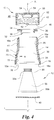
- Fig. 5 illustrates an alternative preferred embodiment of the combination child-resistant package 110 and collapsible tube 112.
- the reference numerals of the alternative embodiment are distinguishable from those of the first embodiment by a factor of one-hundred (100), but otherwise indicate the same elements as indicated in the first embodiment, except as otherwise specified.
- the combination child-resistant package 110 and collapsible tube 112 of the alternative embodiment is substantially similar to that of the first embodiment.
- the description of certain similarities between the embodiments may be omitted herein for the sake of brevity and convenience, and, therefore, is not limiting.
- a distinguishing feature of the alternative embodiment is that at least a lower portion of the sidewall 120 of the body 114 has a generally elliptical or oval shape when viewed from below, while an opposing upper portion of the sidewall 120 of the body 114 has a generally circular shape when viewed from below.
- the body 114 may be designed to more closely or even exactly match and/or complement a shape of the tube 112.
- the body 114 may have any number of sized, shapes and/or configurations, and the present invention is not limited to one particular design or arrangement of the body 114.
Landscapes
- Engineering & Computer Science (AREA)
- Mechanical Engineering (AREA)
- Packages (AREA)
- Tubes (AREA)
- Medical Preparation Storing Or Oral Administration Devices (AREA)
- Details Of Rigid Or Semi-Rigid Containers (AREA)
Claims (13)
- Combinaison comprenant :un emballage à l'épreuve des enfants (10) comportant :un corps (14) ayant une première extrémité généralement ouverte (16), une seconde extrémité opposée généralement ouverte (18), et une paroi latérale (20) s'étendant de la première extrémité (16) à la seconde extrémité (18), la paroi latérale (20) ayant une surface intérieure (22) et une surface extérieure opposée (24), un axe longitudinal A du corps (14) s'étendant de la première extrémité (16) à la seconde extrémité (18), une cavité (30) étant définie par le corps (14) ;une paroi de dessous (40) positionnée à proximité de la seconde extrémité ouverte (18) du corps (14), la paroi de dessous (40) fermant généralement la seconde extrémité ouverte (18) du corps (14), la paroi de dessous (40) pouvant être montée sur au moins une portion de la seconde extrémité (18) du corps (14) ;un bouchon (42) pouvant être monté de façon amovible sur au moins une portion de la première extrémité (16) du corps (14) ; etun tube souple (12) positionnable de façon amovible dans la cavité (30) du corps (14) et entouré par le corps (14), la paroi de dessous (40) et le bouchon (42) lorsque le bouchon (42) est monté sur au moins une portion de la première extrémité (16) du corps (14), le tube souple (12) comportant :un logement généralement flexible (56) définissant une cavité (58) pour contenir une substance à distribuer depuis le logement (56) ;un dispositif de fermeture (60) monté de façon amovible sur le logement (56) ; etl'emballage à l'épreuve des enfants (10) comporte en outre un collier (38) positionné au niveau de la première extrémité (16) du corps (14), une ouverture (32) positionnée à proximité de la première extrémité ouverte (16) du corps (14) et s'étendant à travers le collier (38), l'ouverture (32) étant plus petite que la première extrémité ouverte (16) du corps (14) et dans laquelle le collier (38) peut être monté de façon amovible sur au moins une portion de la première extrémité (16) du corps (14),caractérisée en ce quele tube souple (12) est mobile au sein du corps (14) selon l'axe longitudinal A entre une première position et une seconde position, la première position étant espacée de la seconde position selon l'axe longitudinal A, dans la première position le tube souple (12) entier étant positionné en dessous de la première extrémité (16) du corps (14) de l'emballage (10), dans la seconde position au moins une portion du tube souple (12) étant positionnée au-dessus de la première extrémité (16) du corps (14) de l'emballage (10) et s'étendant vers l'extérieur au-delà de l'emballage (10), et en ce que le collier (38) peut s'enclencher avec le tube souple (12) avec le bouchon (42) enlevé du corps (14), et le collier (38) étant désenclenché du tube souple (12) à l'intérieur d'un emballage à l'épreuve des enfants (10) totalement assemblé avec le bouchon (42) monté sur le corps (14).
- Combinaison selon la revendication 1, dans laquelle l'ouverture (32) a une première portion (26) et une seconde portion (28), la première portion (26) s'étendant généralement parallèle à l'axe longitudinal A, la seconde portion (28) s'étendant à un angle d'approximativement 45 degrés par rapport à l'axe longitudinal A.
- Combinaison selon la revendication 1, dans laquelle le bouchon (42) comporte une paroi de base (50) et une jupe (52) s'étendant vers le bas depuis celle-ci, au moins une saillie (54) s'étendant vers le bas depuis la paroi de base (50), la saillie (54) étant espacée de la jupe (52), au moins une portion de la saillie (54) entourant au moins une portion du dispositif de fermeture (60) lorsque le dispositif de fermeture (60) est monté sur le logement (56) et le tube souple (12) est positionné dans la cavité (30) du corps (14).
- Combinaison selon la revendication 1, dans laquelle la surface intérieure de la paroi latérale (20) du corps (14) a une première portion (26) à proximité de la première extrémité (16) du corps (14) et une seconde portion (28) à proximité de la seconde extrémité (18) du corps (14), la première portion (26) s'étendant généralement parallèle à l'axe longitudinal A, la seconde portion (28) s'étendant à un angle qui s'étend vers l'intérieur vers l'axe longitudinal A.
- Combinaison selon la revendication 1, dans laquelle au moins une portion du tube souple (12) est plus grande que l'ouverture (32) pour empêcher le tube souple (12) d'être enlevé totalement du corps (14).
- Combinaison selon la revendication 1, dans laquelle au moins une portion du tube souple (12) est plus petite que l'ouverture (32) pour permettre à au moins une portion du tube souple (12) d'être déplacée à travers l'ouverture (32).
- Combinaison selon la revendication 1, dans laquelle l'emballage à l'épreuve des enfants (10) comporte en outre :un premier filet (44) sur la surface extérieure de la paroi latérale (20) du corps (14) à proximité de la première extrémité (16) de celui-ci ; etun second filet complémentaire (46) sur une surface intérieure du bouchon (42),dans laquelle le premier filet (44) s'enclenche avec le second filet (46) lorsque le bouchon (42) est monté sur le corps.
- Combinaison selon la revendication 1, comprenant en outre la substance à distribuer depuis le logement (56) du tube souple (12).
- Combinaison selon la revendication 8, dans laquelle la substance comprend une composition pharmaceutique.
- Combinaison selon la revendication 9, comprenant un support pharmaceutiquement acceptable et au moins un ingrédient pharmaceutique actif choisi dans le groupe consistant en l'ivermectine, la brimonidine, le trifarotène, l'adapalène, le clobétasol, et la bétaméthasone.
- Procédé d'utilisation d'un emballage à l'épreuve des enfants (10) pour un tube souple (12), le procédé comprenant :l'obtention ou la fourniture d'une combinaison comprenant un emballage à l'épreuve des enfants (10) ayant un corps et un bouchon (42) fixé de façon amovible à une première extrémité (16) de celui-ci et un tube souple (12) selon au moins l'une des revendications 1 à 10 ;l'insertion du tube souple (12) dans la seconde extrémité ouverte (18) du corps (14) ; etla fixation de la paroi de dessous (40) à la seconde extrémité ouverte (18) du corps (14) pour renfermer le tube souple (12) au sein de l'emballage (10).
- Procédé selon la revendication 11, comprenant en outre :l'enlèvement du bouchon (42) du corps (14) ;le déplacement du tube souple (12) par rapport au corps (14) pour exposer au moins une portion du tube souple (12) ;l'enlèvement d'au moins une partie de la substance depuis le tube souple (12) ;le déplacement du tube souple (12) par rapport au corps de sorte que le tube souple (12) entier soit entouré par le corps (14) ; etla fixation du bouchon (42) au corps (14) pour renfermer le tube souple (12) au sein de l'emballage (10).
- Procédé selon la revendication 11, comprenant en outre :l'enlèvement du bouchon (42) du corps (14) ;l'enlèvement d'un collier (38) du corps (14) ; etl'enlèvement du tube souple (12) du corps (14) pour jeter ou remplir à nouveau le tube souple (12).
Applications Claiming Priority (2)
| Application Number | Priority Date | Filing Date | Title |
|---|---|---|---|
| US13/729,195 US9499310B2 (en) | 2012-12-28 | 2012-12-28 | Combination child-resistant package and collapsible tube, and method of using same |
| PCT/US2013/077766 WO2014105931A2 (fr) | 2012-12-28 | 2013-12-26 | Emballage et tube pouvant être écrasé de protection-enfant en combinaison, et leur procédé d'utilisation |
Publications (2)
| Publication Number | Publication Date |
|---|---|
| EP2938557A2 EP2938557A2 (fr) | 2015-11-04 |
| EP2938557B1 true EP2938557B1 (fr) | 2019-02-13 |
Family
ID=50000089
Family Applications (1)
| Application Number | Title | Priority Date | Filing Date |
|---|---|---|---|
| EP13824064.3A Active EP2938557B1 (fr) | 2012-12-28 | 2013-12-26 | Ensemble emballage avec securite enfant et tube deformable, ainsi que son procédé d'utilisation |
Country Status (11)
| Country | Link |
|---|---|
| US (1) | US9499310B2 (fr) |
| EP (1) | EP2938557B1 (fr) |
| JP (1) | JP2016503746A (fr) |
| KR (1) | KR20150138156A (fr) |
| CN (1) | CN104936867A (fr) |
| AU (1) | AU2013370396A1 (fr) |
| BR (1) | BR112015015145A2 (fr) |
| CA (1) | CA2895382A1 (fr) |
| MX (1) | MX2015008472A (fr) |
| RU (1) | RU2015131096A (fr) |
| WO (1) | WO2014105931A2 (fr) |
Families Citing this family (4)
| Publication number | Priority date | Publication date | Assignee | Title |
|---|---|---|---|---|
| US20150090622A1 (en) * | 2013-10-01 | 2015-04-02 | Erin L. Bassi | Pouchkin |
| BR112016010229A2 (pt) * | 2013-11-06 | 2017-08-08 | Procter & Gamble | recipientes que têm um volume de produto e uma estrutura separada acoplada aos mesmos |
| CA2981847C (fr) | 2015-04-10 | 2019-03-12 | The Procter & Gamble Company | Contenants souples comprenant des joints de renforcement |
| US10343827B2 (en) * | 2017-01-02 | 2019-07-09 | Innovative Product Brands, Inc. | Child-resistant locking cap for laminated tubes |
Family Cites Families (28)
| Publication number | Priority date | Publication date | Assignee | Title |
|---|---|---|---|---|
| US2711766A (en) | 1949-10-15 | 1955-06-28 | Injection Molding Company | Container |
| US2556584A (en) | 1950-10-04 | 1951-06-12 | Hofmann Frank Joseph | Holder and protector for collapsible paste tubes |
| US2793012A (en) | 1954-05-06 | 1957-05-21 | Wallace P Wolf | Sediment stirrer |
| US3464599A (en) | 1964-09-22 | 1969-09-02 | Rainbow Crafts Inc | Spill-proof container |
| US3275180A (en) * | 1965-01-04 | 1966-09-27 | Lermer Packaging Corp | Mailing container construction |
| CH450645A (de) * | 1967-05-24 | 1968-01-31 | Chandor S A | Vorrichtung zur Ausgabe von bestimmten Portionen kosmetischer Produkte |
| GB1391904A (en) | 1971-04-16 | 1975-04-23 | Eckholm R J | Disposable containers |
| US3868036A (en) | 1972-12-13 | 1975-02-25 | John C Wittwer | Safety package for collapsible tubes |
| US4174051A (en) * | 1978-07-26 | 1979-11-13 | The Continental Group, Inc. | Protective locking flaps for opening in sealed corrugated containers |
| US4215785A (en) * | 1979-03-22 | 1980-08-05 | Josef Schwaiger | Baby feeding bottle |
| USD260657S (en) | 1979-04-09 | 1981-09-08 | Shachihata Industrial Co., Ltd. | Felt pen |
| USD267234S (en) | 1979-12-20 | 1982-12-14 | Astra-Syntex Scandinavia Aktiebolag | Dispensing container for pills or the like |
| USD286674S (en) | 1983-12-27 | 1986-11-11 | Earl Hoyt | Vapor dispensing device |
| US4706827A (en) * | 1984-04-12 | 1987-11-17 | Baxter Travenol Laboratories, Inc. | Container such as a nursing container, and packaging arrangement therefor |
| USD286675S (en) | 1984-05-21 | 1986-11-11 | Earl Hoyt | Vapor dispensing device |
| USD294637S (en) | 1985-06-10 | 1988-03-08 | Airwick Industries, Inc. | Vapor dispensing container |
| AU6648694A (en) | 1993-04-26 | 1994-11-21 | Lingner & Fischer Gmbh | Dispenser |
| USD362799S (en) | 1994-11-15 | 1995-10-03 | Apothecary Product, Inc. | Combined bottle and spoon |
| USD410842S (en) | 1996-07-26 | 1999-06-08 | Pfizer Inc. | Bottle protecting container |
| US6085927A (en) | 1999-07-12 | 2000-07-11 | Owens-Illinois Closure Inc. | Container with insert to reduce effective volume and package incorporating same |
| US6386405B1 (en) | 2000-12-18 | 2002-05-14 | Royal Packaging Industries Van Leer Nv | Snap on closure and method |
| ES2325951T3 (es) | 2001-08-29 | 2009-09-25 | Pharmakodex Limited | Dispositivo de administracion topica. |
| USD481949S1 (en) | 2002-01-25 | 2003-11-11 | Lumson Spa | Bottle |
| US6616000B1 (en) * | 2002-04-19 | 2003-09-09 | Playtex Products, Inc. | Infant feeding and storage system |
| USD566558S1 (en) | 2006-09-08 | 2008-04-15 | Db Design Gmbh | Cosmetic container |
| WO2008102066A1 (fr) | 2007-02-19 | 2008-08-28 | Roger Le Faucheur | Flacon pour tube de dentifrice |
| USD617449S1 (en) | 2007-09-24 | 2010-06-08 | Willie Roy Walker | Urine stream directing device |
| USD657249S1 (en) | 2010-07-30 | 2012-04-10 | Db Design Gmbh | Jar |
-
2012
- 2012-12-28 US US13/729,195 patent/US9499310B2/en active Active
-
2013
- 2013-12-26 AU AU2013370396A patent/AU2013370396A1/en not_active Abandoned
- 2013-12-26 CA CA2895382A patent/CA2895382A1/fr not_active Abandoned
- 2013-12-26 CN CN201380068126.6A patent/CN104936867A/zh active Pending
- 2013-12-26 BR BR112015015145A patent/BR112015015145A2/pt not_active Application Discontinuation
- 2013-12-26 JP JP2015550758A patent/JP2016503746A/ja not_active Withdrawn
- 2013-12-26 WO PCT/US2013/077766 patent/WO2014105931A2/fr active Application Filing
- 2013-12-26 MX MX2015008472A patent/MX2015008472A/es unknown
- 2013-12-26 KR KR1020157020290A patent/KR20150138156A/ko not_active Application Discontinuation
- 2013-12-26 EP EP13824064.3A patent/EP2938557B1/fr active Active
- 2013-12-26 RU RU2015131096A patent/RU2015131096A/ru not_active Application Discontinuation
Non-Patent Citations (1)
| Title |
|---|
| None * |
Also Published As
| Publication number | Publication date |
|---|---|
| MX2015008472A (es) | 2016-10-26 |
| CN104936867A (zh) | 2015-09-23 |
| WO2014105931A3 (fr) | 2014-10-09 |
| WO2014105931A2 (fr) | 2014-07-03 |
| AU2013370396A1 (en) | 2015-07-02 |
| JP2016503746A (ja) | 2016-02-08 |
| US9499310B2 (en) | 2016-11-22 |
| US20140183223A1 (en) | 2014-07-03 |
| RU2015131096A (ru) | 2017-02-01 |
| KR20150138156A (ko) | 2015-12-09 |
| EP2938557A2 (fr) | 2015-11-04 |
| BR112015015145A2 (pt) | 2017-07-11 |
| CA2895382A1 (fr) | 2014-07-03 |
Similar Documents
| Publication | Publication Date | Title |
|---|---|---|
| US9694956B2 (en) | Dispensing and mixing device | |
| US8839982B1 (en) | Dispensing capsule with dual independent dispensing chambers | |
| JP6111205B2 (ja) | 調合製品用の蓋・容器アセンブリ | |
| US8887905B2 (en) | Plastic closure having a capsule for dispensing active ingredients | |
| EP2938557B1 (fr) | Ensemble emballage avec securite enfant et tube deformable, ainsi que son procédé d'utilisation | |
| US7168461B2 (en) | Combination spoon and cap for container | |
| US20110147252A1 (en) | Packages and inserts useful for dispensing medicines | |
| GB2559453A (en) | A liquid container with a piston dispenser | |
| EP2938550B1 (fr) | Combinaison de contenant et de dispositif et son procédé d'utilisation | |
| AU2020296206B2 (en) | Container system for mixing and dispensing | |
| US20110155757A1 (en) | Packages and inserts thereof with guide wall for dispensing medicinal units | |
| US5119560A (en) | Medicine dosage device | |
| US20170050767A1 (en) | Pressurized package | |
| US10029821B2 (en) | Retainable scoop and container | |
| US5388698A (en) | Pocket carrier for dispensing products in precise quantitites | |
| US20190374432A1 (en) | Pill container with cap | |
| US20130152515A1 (en) | Tablet storage system and use thereof | |
| US11858684B2 (en) | Dispensing system | |
| US5213213A (en) | Medication container | |
| US7604124B1 (en) | Dispensing container and package for pelletized products | |
| US20200102136A1 (en) | Kits and bottle inserts | |
| KR20170075304A (ko) | 정량 토출용 캡이 구비된 포장용기 | |
| AU2004242481A1 (en) | Container |
Legal Events
| Date | Code | Title | Description |
|---|---|---|---|
| PUAI | Public reference made under article 153(3) epc to a published international application that has entered the european phase |
Free format text: ORIGINAL CODE: 0009012 |
|
| 17P | Request for examination filed |
Effective date: 20150622 |
|
| AK | Designated contracting states |
Kind code of ref document: A2 Designated state(s): AL AT BE BG CH CY CZ DE DK EE ES FI FR GB GR HR HU IE IS IT LI LT LU LV MC MK MT NL NO PL PT RO RS SE SI SK SM TR |
|
| AX | Request for extension of the european patent |
Extension state: BA ME |
|
| DAX | Request for extension of the european patent (deleted) | ||
| STAA | Information on the status of an ep patent application or granted ep patent |
Free format text: STATUS: EXAMINATION IS IN PROGRESS |
|
| 17Q | First examination report despatched |
Effective date: 20171121 |
|
| GRAP | Despatch of communication of intention to grant a patent |
Free format text: ORIGINAL CODE: EPIDOSNIGR1 |
|
| STAA | Information on the status of an ep patent application or granted ep patent |
Free format text: STATUS: GRANT OF PATENT IS INTENDED |
|
| INTG | Intention to grant announced |
Effective date: 20180601 |
|
| GRAS | Grant fee paid |
Free format text: ORIGINAL CODE: EPIDOSNIGR3 |
|
| GRAJ | Information related to disapproval of communication of intention to grant by the applicant or resumption of examination proceedings by the epo deleted |
Free format text: ORIGINAL CODE: EPIDOSDIGR1 |
|
| GRAL | Information related to payment of fee for publishing/printing deleted |
Free format text: ORIGINAL CODE: EPIDOSDIGR3 |
|
| STAA | Information on the status of an ep patent application or granted ep patent |
Free format text: STATUS: EXAMINATION IS IN PROGRESS |
|
| GRAP | Despatch of communication of intention to grant a patent |
Free format text: ORIGINAL CODE: EPIDOSNIGR1 |
|
| STAA | Information on the status of an ep patent application or granted ep patent |
Free format text: STATUS: GRANT OF PATENT IS INTENDED |
|
| INTC | Intention to grant announced (deleted) | ||
| GRAA | (expected) grant |
Free format text: ORIGINAL CODE: 0009210 |
|
| STAA | Information on the status of an ep patent application or granted ep patent |
Free format text: STATUS: THE PATENT HAS BEEN GRANTED |
|
| INTG | Intention to grant announced |
Effective date: 20181219 |
|
| AK | Designated contracting states |
Kind code of ref document: B1 Designated state(s): AL AT BE BG CH CY CZ DE DK EE ES FI FR GB GR HR HU IE IS IT LI LT LU LV MC MK MT NL NO PL PT RO RS SE SI SK SM TR |
|
| REG | Reference to a national code |
Ref country code: GB Ref legal event code: FG4D |
|
| REG | Reference to a national code |
Ref country code: CH Ref legal event code: EP Ref country code: AT Ref legal event code: REF Ref document number: 1096068 Country of ref document: AT Kind code of ref document: T Effective date: 20190215 |
|
| REG | Reference to a national code |
Ref country code: IE Ref legal event code: FG4D |
|
| REG | Reference to a national code |
Ref country code: DE Ref legal event code: R096 Ref document number: 602013050818 Country of ref document: DE |
|
| REG | Reference to a national code |
Ref country code: LT Ref legal event code: MG4D |
|
| REG | Reference to a national code |
Ref country code: NL Ref legal event code: MP Effective date: 20190213 |
|
| PG25 | Lapsed in a contracting state [announced via postgrant information from national office to epo] |
Ref country code: NL Free format text: LAPSE BECAUSE OF FAILURE TO SUBMIT A TRANSLATION OF THE DESCRIPTION OR TO PAY THE FEE WITHIN THE PRESCRIBED TIME-LIMIT Effective date: 20190213 Ref country code: LT Free format text: LAPSE BECAUSE OF FAILURE TO SUBMIT A TRANSLATION OF THE DESCRIPTION OR TO PAY THE FEE WITHIN THE PRESCRIBED TIME-LIMIT Effective date: 20190213 Ref country code: FI Free format text: LAPSE BECAUSE OF FAILURE TO SUBMIT A TRANSLATION OF THE DESCRIPTION OR TO PAY THE FEE WITHIN THE PRESCRIBED TIME-LIMIT Effective date: 20190213 Ref country code: PT Free format text: LAPSE BECAUSE OF FAILURE TO SUBMIT A TRANSLATION OF THE DESCRIPTION OR TO PAY THE FEE WITHIN THE PRESCRIBED TIME-LIMIT Effective date: 20190613 Ref country code: NO Free format text: LAPSE BECAUSE OF FAILURE TO SUBMIT A TRANSLATION OF THE DESCRIPTION OR TO PAY THE FEE WITHIN THE PRESCRIBED TIME-LIMIT Effective date: 20190513 Ref country code: SE Free format text: LAPSE BECAUSE OF FAILURE TO SUBMIT A TRANSLATION OF THE DESCRIPTION OR TO PAY THE FEE WITHIN THE PRESCRIBED TIME-LIMIT Effective date: 20190213 |
|
| PG25 | Lapsed in a contracting state [announced via postgrant information from national office to epo] |
Ref country code: GR Free format text: LAPSE BECAUSE OF FAILURE TO SUBMIT A TRANSLATION OF THE DESCRIPTION OR TO PAY THE FEE WITHIN THE PRESCRIBED TIME-LIMIT Effective date: 20190514 Ref country code: HR Free format text: LAPSE BECAUSE OF FAILURE TO SUBMIT A TRANSLATION OF THE DESCRIPTION OR TO PAY THE FEE WITHIN THE PRESCRIBED TIME-LIMIT Effective date: 20190213 Ref country code: BG Free format text: LAPSE BECAUSE OF FAILURE TO SUBMIT A TRANSLATION OF THE DESCRIPTION OR TO PAY THE FEE WITHIN THE PRESCRIBED TIME-LIMIT Effective date: 20190513 Ref country code: IS Free format text: LAPSE BECAUSE OF FAILURE TO SUBMIT A TRANSLATION OF THE DESCRIPTION OR TO PAY THE FEE WITHIN THE PRESCRIBED TIME-LIMIT Effective date: 20190613 Ref country code: LV Free format text: LAPSE BECAUSE OF FAILURE TO SUBMIT A TRANSLATION OF THE DESCRIPTION OR TO PAY THE FEE WITHIN THE PRESCRIBED TIME-LIMIT Effective date: 20190213 Ref country code: RS Free format text: LAPSE BECAUSE OF FAILURE TO SUBMIT A TRANSLATION OF THE DESCRIPTION OR TO PAY THE FEE WITHIN THE PRESCRIBED TIME-LIMIT Effective date: 20190213 |
|
| REG | Reference to a national code |
Ref country code: AT Ref legal event code: MK05 Ref document number: 1096068 Country of ref document: AT Kind code of ref document: T Effective date: 20190213 |
|
| PG25 | Lapsed in a contracting state [announced via postgrant information from national office to epo] |
Ref country code: CZ Free format text: LAPSE BECAUSE OF FAILURE TO SUBMIT A TRANSLATION OF THE DESCRIPTION OR TO PAY THE FEE WITHIN THE PRESCRIBED TIME-LIMIT Effective date: 20190213 Ref country code: RO Free format text: LAPSE BECAUSE OF FAILURE TO SUBMIT A TRANSLATION OF THE DESCRIPTION OR TO PAY THE FEE WITHIN THE PRESCRIBED TIME-LIMIT Effective date: 20190213 Ref country code: SK Free format text: LAPSE BECAUSE OF FAILURE TO SUBMIT A TRANSLATION OF THE DESCRIPTION OR TO PAY THE FEE WITHIN THE PRESCRIBED TIME-LIMIT Effective date: 20190213 Ref country code: ES Free format text: LAPSE BECAUSE OF FAILURE TO SUBMIT A TRANSLATION OF THE DESCRIPTION OR TO PAY THE FEE WITHIN THE PRESCRIBED TIME-LIMIT Effective date: 20190213 Ref country code: AL Free format text: LAPSE BECAUSE OF FAILURE TO SUBMIT A TRANSLATION OF THE DESCRIPTION OR TO PAY THE FEE WITHIN THE PRESCRIBED TIME-LIMIT Effective date: 20190213 Ref country code: EE Free format text: LAPSE BECAUSE OF FAILURE TO SUBMIT A TRANSLATION OF THE DESCRIPTION OR TO PAY THE FEE WITHIN THE PRESCRIBED TIME-LIMIT Effective date: 20190213 Ref country code: IT Free format text: LAPSE BECAUSE OF FAILURE TO SUBMIT A TRANSLATION OF THE DESCRIPTION OR TO PAY THE FEE WITHIN THE PRESCRIBED TIME-LIMIT Effective date: 20190213 Ref country code: DK Free format text: LAPSE BECAUSE OF FAILURE TO SUBMIT A TRANSLATION OF THE DESCRIPTION OR TO PAY THE FEE WITHIN THE PRESCRIBED TIME-LIMIT Effective date: 20190213 |
|
| REG | Reference to a national code |
Ref country code: DE Ref legal event code: R097 Ref document number: 602013050818 Country of ref document: DE |
|
| PG25 | Lapsed in a contracting state [announced via postgrant information from national office to epo] |
Ref country code: PL Free format text: LAPSE BECAUSE OF FAILURE TO SUBMIT A TRANSLATION OF THE DESCRIPTION OR TO PAY THE FEE WITHIN THE PRESCRIBED TIME-LIMIT Effective date: 20190213 Ref country code: SM Free format text: LAPSE BECAUSE OF FAILURE TO SUBMIT A TRANSLATION OF THE DESCRIPTION OR TO PAY THE FEE WITHIN THE PRESCRIBED TIME-LIMIT Effective date: 20190213 |
|
| PLBE | No opposition filed within time limit |
Free format text: ORIGINAL CODE: 0009261 |
|
| STAA | Information on the status of an ep patent application or granted ep patent |
Free format text: STATUS: NO OPPOSITION FILED WITHIN TIME LIMIT |
|
| PG25 | Lapsed in a contracting state [announced via postgrant information from national office to epo] |
Ref country code: AT Free format text: LAPSE BECAUSE OF FAILURE TO SUBMIT A TRANSLATION OF THE DESCRIPTION OR TO PAY THE FEE WITHIN THE PRESCRIBED TIME-LIMIT Effective date: 20190213 |
|
| 26N | No opposition filed |
Effective date: 20191114 |
|
| PG25 | Lapsed in a contracting state [announced via postgrant information from national office to epo] |
Ref country code: SI Free format text: LAPSE BECAUSE OF FAILURE TO SUBMIT A TRANSLATION OF THE DESCRIPTION OR TO PAY THE FEE WITHIN THE PRESCRIBED TIME-LIMIT Effective date: 20190213 |
|
| PG25 | Lapsed in a contracting state [announced via postgrant information from national office to epo] |
Ref country code: TR Free format text: LAPSE BECAUSE OF FAILURE TO SUBMIT A TRANSLATION OF THE DESCRIPTION OR TO PAY THE FEE WITHIN THE PRESCRIBED TIME-LIMIT Effective date: 20190213 |
|
| REG | Reference to a national code |
Ref country code: CH Ref legal event code: PL |
|
| REG | Reference to a national code |
Ref country code: BE Ref legal event code: MM Effective date: 20191231 |
|
| PG25 | Lapsed in a contracting state [announced via postgrant information from national office to epo] |
Ref country code: MC Free format text: LAPSE BECAUSE OF FAILURE TO SUBMIT A TRANSLATION OF THE DESCRIPTION OR TO PAY THE FEE WITHIN THE PRESCRIBED TIME-LIMIT Effective date: 20190213 |
|
| PG25 | Lapsed in a contracting state [announced via postgrant information from national office to epo] |
Ref country code: IE Free format text: LAPSE BECAUSE OF NON-PAYMENT OF DUE FEES Effective date: 20191226 Ref country code: LU Free format text: LAPSE BECAUSE OF NON-PAYMENT OF DUE FEES Effective date: 20191226 |
|
| PG25 | Lapsed in a contracting state [announced via postgrant information from national office to epo] |
Ref country code: CH Free format text: LAPSE BECAUSE OF NON-PAYMENT OF DUE FEES Effective date: 20191231 Ref country code: LI Free format text: LAPSE BECAUSE OF NON-PAYMENT OF DUE FEES Effective date: 20191231 Ref country code: BE Free format text: LAPSE BECAUSE OF NON-PAYMENT OF DUE FEES Effective date: 20191231 |
|
| PG25 | Lapsed in a contracting state [announced via postgrant information from national office to epo] |
Ref country code: CY Free format text: LAPSE BECAUSE OF FAILURE TO SUBMIT A TRANSLATION OF THE DESCRIPTION OR TO PAY THE FEE WITHIN THE PRESCRIBED TIME-LIMIT Effective date: 20190213 |
|
| PG25 | Lapsed in a contracting state [announced via postgrant information from national office to epo] |
Ref country code: MT Free format text: LAPSE BECAUSE OF FAILURE TO SUBMIT A TRANSLATION OF THE DESCRIPTION OR TO PAY THE FEE WITHIN THE PRESCRIBED TIME-LIMIT Effective date: 20190213 Ref country code: HU Free format text: LAPSE BECAUSE OF FAILURE TO SUBMIT A TRANSLATION OF THE DESCRIPTION OR TO PAY THE FEE WITHIN THE PRESCRIBED TIME-LIMIT; INVALID AB INITIO Effective date: 20131226 |
|
| REG | Reference to a national code |
Ref country code: DE Ref legal event code: R082 Ref document number: 602013050818 Country of ref document: DE Representative=s name: BOBZIEN, HANS CHRISTOPH, DIPL.-ING, DE Ref country code: DE Ref legal event code: R082 Ref document number: 602013050818 Country of ref document: DE Representative=s name: WAGNER ALBIGER & PARTNER PATENTANWAELTE MBB, DE |
|
| PG25 | Lapsed in a contracting state [announced via postgrant information from national office to epo] |
Ref country code: MK Free format text: LAPSE BECAUSE OF FAILURE TO SUBMIT A TRANSLATION OF THE DESCRIPTION OR TO PAY THE FEE WITHIN THE PRESCRIBED TIME-LIMIT Effective date: 20190213 |
|
| PGFP | Annual fee paid to national office [announced via postgrant information from national office to epo] |
Ref country code: GB Payment date: 20221223 Year of fee payment: 10 Ref country code: FR Payment date: 20221222 Year of fee payment: 10 Ref country code: DE Payment date: 20220620 Year of fee payment: 10 |
|
| REG | Reference to a national code |
Ref country code: DE Ref legal event code: R082 Ref document number: 602013050818 Country of ref document: DE Representative=s name: BOBZIEN, HANS CHRISTOPH, DIPL.-ING, DE |