EP2938430B1 - Multistrukturierter reaktor aus monolithischen wärmeleitenden körpern für chemische prozesse mit hohem wärmeaustausch - Google Patents
Multistrukturierter reaktor aus monolithischen wärmeleitenden körpern für chemische prozesse mit hohem wärmeaustausch Download PDFInfo
- Publication number
- EP2938430B1 EP2938430B1 EP13818226.6A EP13818226A EP2938430B1 EP 2938430 B1 EP2938430 B1 EP 2938430B1 EP 13818226 A EP13818226 A EP 13818226A EP 2938430 B1 EP2938430 B1 EP 2938430B1
- Authority
- EP
- European Patent Office
- Prior art keywords
- tubular element
- monolithic
- thermoconductive
- bodies
- structured
- Prior art date
- Legal status (The legal status is an assumption and is not a legal conclusion. Google has not performed a legal analysis and makes no representation as to the accuracy of the status listed.)
- Active
Links
Images

Classifications
-
- C—CHEMISTRY; METALLURGY
- C10—PETROLEUM, GAS OR COKE INDUSTRIES; TECHNICAL GASES CONTAINING CARBON MONOXIDE; FUELS; LUBRICANTS; PEAT
- C10G—CRACKING HYDROCARBON OILS; PRODUCTION OF LIQUID HYDROCARBON MIXTURES, e.g. BY DESTRUCTIVE HYDROGENATION, OLIGOMERISATION, POLYMERISATION; RECOVERY OF HYDROCARBON OILS FROM OIL-SHALE, OIL-SAND, OR GASES; REFINING MIXTURES MAINLY CONSISTING OF HYDROCARBONS; REFORMING OF NAPHTHA; MINERAL WAXES
- C10G2/00—Production of liquid hydrocarbon mixtures of undefined composition from oxides of carbon
- C10G2/30—Production of liquid hydrocarbon mixtures of undefined composition from oxides of carbon from carbon monoxide with hydrogen
- C10G2/32—Production of liquid hydrocarbon mixtures of undefined composition from oxides of carbon from carbon monoxide with hydrogen with the use of catalysts
- C10G2/34—Apparatus, reactors
- C10G2/341—Apparatus, reactors with stationary catalyst bed
-
- B—PERFORMING OPERATIONS; TRANSPORTING
- B01—PHYSICAL OR CHEMICAL PROCESSES OR APPARATUS IN GENERAL
- B01J—CHEMICAL OR PHYSICAL PROCESSES, e.g. CATALYSIS OR COLLOID CHEMISTRY; THEIR RELEVANT APPARATUS
- B01J8/00—Chemical or physical processes in general, conducted in the presence of fluids and solid particles; Apparatus for such processes
- B01J8/02—Chemical or physical processes in general, conducted in the presence of fluids and solid particles; Apparatus for such processes with stationary particles, e.g. in fixed beds
- B01J8/06—Chemical or physical processes in general, conducted in the presence of fluids and solid particles; Apparatus for such processes with stationary particles, e.g. in fixed beds in tube reactors; the solid particles being arranged in tubes
-
- B—PERFORMING OPERATIONS; TRANSPORTING
- B01—PHYSICAL OR CHEMICAL PROCESSES OR APPARATUS IN GENERAL
- B01J—CHEMICAL OR PHYSICAL PROCESSES, e.g. CATALYSIS OR COLLOID CHEMISTRY; THEIR RELEVANT APPARATUS
- B01J19/00—Chemical, physical or physico-chemical processes in general; Their relevant apparatus
- B01J19/24—Stationary reactors without moving elements inside
- B01J19/248—Reactors comprising multiple separated flow channels
- B01J19/2485—Monolithic reactors
-
- C—CHEMISTRY; METALLURGY
- C10—PETROLEUM, GAS OR COKE INDUSTRIES; TECHNICAL GASES CONTAINING CARBON MONOXIDE; FUELS; LUBRICANTS; PEAT
- C10G—CRACKING HYDROCARBON OILS; PRODUCTION OF LIQUID HYDROCARBON MIXTURES, e.g. BY DESTRUCTIVE HYDROGENATION, OLIGOMERISATION, POLYMERISATION; RECOVERY OF HYDROCARBON OILS FROM OIL-SHALE, OIL-SAND, OR GASES; REFINING MIXTURES MAINLY CONSISTING OF HYDROCARBONS; REFORMING OF NAPHTHA; MINERAL WAXES
- C10G2/00—Production of liquid hydrocarbon mixtures of undefined composition from oxides of carbon
- C10G2/30—Production of liquid hydrocarbon mixtures of undefined composition from oxides of carbon from carbon monoxide with hydrogen
- C10G2/32—Production of liquid hydrocarbon mixtures of undefined composition from oxides of carbon from carbon monoxide with hydrogen with the use of catalysts
- C10G2/33—Production of liquid hydrocarbon mixtures of undefined composition from oxides of carbon from carbon monoxide with hydrogen with the use of catalysts characterised by the catalyst used
- C10G2/331—Production of liquid hydrocarbon mixtures of undefined composition from oxides of carbon from carbon monoxide with hydrogen with the use of catalysts characterised by the catalyst used containing group VIII-metals
- C10G2/332—Production of liquid hydrocarbon mixtures of undefined composition from oxides of carbon from carbon monoxide with hydrogen with the use of catalysts characterised by the catalyst used containing group VIII-metals of the iron-group
-
- B—PERFORMING OPERATIONS; TRANSPORTING
- B01—PHYSICAL OR CHEMICAL PROCESSES OR APPARATUS IN GENERAL
- B01J—CHEMICAL OR PHYSICAL PROCESSES, e.g. CATALYSIS OR COLLOID CHEMISTRY; THEIR RELEVANT APPARATUS
- B01J2219/00—Chemical, physical or physico-chemical processes in general; Their relevant apparatus
- B01J2219/24—Stationary reactors without moving elements inside
- B01J2219/2401—Reactors comprising multiple separate flow channels
- B01J2219/2402—Monolithic-type reactors
- B01J2219/2403—Geometry of the channels
- B01J2219/2404—Polygonal
-
- B—PERFORMING OPERATIONS; TRANSPORTING
- B01—PHYSICAL OR CHEMICAL PROCESSES OR APPARATUS IN GENERAL
- B01J—CHEMICAL OR PHYSICAL PROCESSES, e.g. CATALYSIS OR COLLOID CHEMISTRY; THEIR RELEVANT APPARATUS
- B01J2219/00—Chemical, physical or physico-chemical processes in general; Their relevant apparatus
- B01J2219/24—Stationary reactors without moving elements inside
- B01J2219/2401—Reactors comprising multiple separate flow channels
- B01J2219/2402—Monolithic-type reactors
- B01J2219/2403—Geometry of the channels
- B01J2219/2407—Square
-
- B—PERFORMING OPERATIONS; TRANSPORTING
- B01—PHYSICAL OR CHEMICAL PROCESSES OR APPARATUS IN GENERAL
- B01J—CHEMICAL OR PHYSICAL PROCESSES, e.g. CATALYSIS OR COLLOID CHEMISTRY; THEIR RELEVANT APPARATUS
- B01J2219/00—Chemical, physical or physico-chemical processes in general; Their relevant apparatus
- B01J2219/24—Stationary reactors without moving elements inside
- B01J2219/2401—Reactors comprising multiple separate flow channels
- B01J2219/2402—Monolithic-type reactors
- B01J2219/2409—Heat exchange aspects
- B01J2219/2411—The reactant being in indirect heat exchange with a non reacting heat exchange medium
-
- B—PERFORMING OPERATIONS; TRANSPORTING
- B01—PHYSICAL OR CHEMICAL PROCESSES OR APPARATUS IN GENERAL
- B01J—CHEMICAL OR PHYSICAL PROCESSES, e.g. CATALYSIS OR COLLOID CHEMISTRY; THEIR RELEVANT APPARATUS
- B01J2219/00—Chemical, physical or physico-chemical processes in general; Their relevant apparatus
- B01J2219/24—Stationary reactors without moving elements inside
- B01J2219/2401—Reactors comprising multiple separate flow channels
- B01J2219/2402—Monolithic-type reactors
- B01J2219/2425—Construction materials
- B01J2219/2427—Catalysts
- B01J2219/243—Catalyst in granular form in the channels
-
- B—PERFORMING OPERATIONS; TRANSPORTING
- B01—PHYSICAL OR CHEMICAL PROCESSES OR APPARATUS IN GENERAL
- B01J—CHEMICAL OR PHYSICAL PROCESSES, e.g. CATALYSIS OR COLLOID CHEMISTRY; THEIR RELEVANT APPARATUS
- B01J2219/00—Chemical, physical or physico-chemical processes in general; Their relevant apparatus
- B01J2219/24—Stationary reactors without moving elements inside
- B01J2219/2401—Reactors comprising multiple separate flow channels
- B01J2219/2402—Monolithic-type reactors
- B01J2219/2425—Construction materials
- B01J2219/2433—Construction materials of the monoliths
- B01J2219/2434—Metals or alloys
-
- B—PERFORMING OPERATIONS; TRANSPORTING
- B01—PHYSICAL OR CHEMICAL PROCESSES OR APPARATUS IN GENERAL
- B01J—CHEMICAL OR PHYSICAL PROCESSES, e.g. CATALYSIS OR COLLOID CHEMISTRY; THEIR RELEVANT APPARATUS
- B01J2219/00—Chemical, physical or physico-chemical processes in general; Their relevant apparatus
- B01J2219/24—Stationary reactors without moving elements inside
- B01J2219/2401—Reactors comprising multiple separate flow channels
- B01J2219/2402—Monolithic-type reactors
- B01J2219/2441—Other constructional details
- B01J2219/2443—Assembling means of monolith modules
-
- B—PERFORMING OPERATIONS; TRANSPORTING
- B01—PHYSICAL OR CHEMICAL PROCESSES OR APPARATUS IN GENERAL
- B01J—CHEMICAL OR PHYSICAL PROCESSES, e.g. CATALYSIS OR COLLOID CHEMISTRY; THEIR RELEVANT APPARATUS
- B01J2219/00—Chemical, physical or physico-chemical processes in general; Their relevant apparatus
- B01J2219/24—Stationary reactors without moving elements inside
- B01J2219/2401—Reactors comprising multiple separate flow channels
- B01J2219/2402—Monolithic-type reactors
- B01J2219/2441—Other constructional details
- B01J2219/2444—Size aspects
- B01J2219/2445—Sizes
-
- B—PERFORMING OPERATIONS; TRANSPORTING
- B01—PHYSICAL OR CHEMICAL PROCESSES OR APPARATUS IN GENERAL
- B01J—CHEMICAL OR PHYSICAL PROCESSES, e.g. CATALYSIS OR COLLOID CHEMISTRY; THEIR RELEVANT APPARATUS
- B01J2219/00—Chemical, physical or physico-chemical processes in general; Their relevant apparatus
- B01J2219/24—Stationary reactors without moving elements inside
- B01J2219/2401—Reactors comprising multiple separate flow channels
- B01J2219/2402—Monolithic-type reactors
- B01J2219/2441—Other constructional details
- B01J2219/2444—Size aspects
- B01J2219/2446—Cell density
-
- Y—GENERAL TAGGING OF NEW TECHNOLOGICAL DEVELOPMENTS; GENERAL TAGGING OF CROSS-SECTIONAL TECHNOLOGIES SPANNING OVER SEVERAL SECTIONS OF THE IPC; TECHNICAL SUBJECTS COVERED BY FORMER USPC CROSS-REFERENCE ART COLLECTIONS [XRACs] AND DIGESTS
- Y10—TECHNICAL SUBJECTS COVERED BY FORMER USPC
- Y10T—TECHNICAL SUBJECTS COVERED BY FORMER US CLASSIFICATION
- Y10T29/00—Metal working
- Y10T29/49—Method of mechanical manufacture
- Y10T29/49826—Assembling or joining
- Y10T29/49828—Progressively advancing of work assembly station or assembled portion of work
Definitions
- the present invention relates to a multi-structured reactor for chemical processes with a high heat exchange.
- the present invention relates to a reactor for effecting exothermic or endothermic chemical reactions, especially in the presence of a heterogeneous catalyst, attributed to a composition of monolithic parts.
- the present invention relates to a multi-structured reactor for carrying out the Fischer-Tropsch reaction starting from synthesis gas.
- the term "Fischer-Tropsch process or reaction” indicates processes for the preparation of mixtures of prevalently hydrocarbon compounds and in some cases oxygenated aliphatic compounds, or a mixture thereof, by direct synthesis from mixtures of hydrogen and carbon monoxide with a molar ratio H 2 /CO ranging from 1 to 3 (synthesis gas) in the presence of suitable solid catalysts, normally comprising transition metals of groups 8 to 10 of the periodic table.
- suitable solid catalysts normally comprising transition metals of groups 8 to 10 of the periodic table.
- the chemical reaction is developed in substantially three-phase systems in which a gaseous phase flows in contact with the solid catalyst and the reaction product prevalently consists of liquid and gaseous hydrocarbons, at the reaction temperature and water as by-product.
- reactors of the Slurry Bubble Column type allow extremely favourable reaction yields and an effective temperature control, they have a series of operative drawbacks such as, for example, the necessity of having to separate the reaction product from the catalyst in suspension, recovering and recycling the latter, in addition to the difficulty of managing the fluid-dynamic conditions in the reactor in order to have a homogeneous dispersion of the catalyst.
- last-generation industrial reactors for the Fischer-Tropsch synthesis with a catalyst in suspension are characterized by large dimensions, with cylindrical equipment having a height in the order of 60 metres and a diameter in the order of 10 metres.
- the construction and management of these reactors and in particular their maintenance may not be easy to handle.
- Slurry Bubble Column-type reactors An alternative to Slurry Bubble Column-type reactors is represented by fixed-bed reactors. These reactors essentially consist of a device comprising a casing or mantle and a pair of closing elements, upper and lower, in which there are generally feeding means of the reactants and discharging means of the reaction products. A plurality of tubes is inserted inside the mantle, each of which is filled with catalyst, for example, in the form of pellets.
- the reacting gas for example, synthesis gas
- flows inside the tubes enters into contact with the catalytic particles and reacts.
- the reaction heat is removed by a continuous flow of cooling fluid, for example water, which occupies the free volume inside the mantle.
- the main limits of the fixed-bed configuration substantially depend on the intraparticle mass transfer (responsible, for example, for a low activity and selectivity towards the liquid product, in the case of the Fischer-Tropsch reaction) and radial heat transfer inside the reactor, which can create local hot spots with potential deactivation of part of the catalyst, which may be such as to not allow it to carry out the reaction at high rates.
- fixed-bed reactors are characterized by an extremely low specific productivity (per time unit and volume unit of catalyst used). In order to guarantee adequate production volumes, extremely high quantities of catalyst must therefore be used, and consequently very large dimensions of the reactor.
- the catalytic material is distributed in thin layers on the internal walls of the channels of the monolithic structure by means of the deposition technique commonly known as “washcoating", so as to be in contact with the reactants flowing in each channel during the process.
- the monolithic structure guarantees a good heat exchange with the thermo-regulating fluid circulating in the container outside the tube, due to the fact that, as the material of the monolith is characterized by a good thermal conductivity, it favours radial heat transfer.
- WO 2010/130399 proposes a monolithic reactor with more reduced dimensions thanks to a higher volumetric density of the active phase of the catalyst and a more efficient removal system of the reaction heat.
- This reactor is based on tubular monoliths comprising, in a continuous metallic matrix having a high conductivity, a series of longitudinal channels having suitable dimensions, filled with catalyst in granule form.
- a first object of the present invention relates to a multi-structured tubular element of a reactor for effecting exothermic/endothermic chemical reactions as defined by claim 1, said element:
- the honeycomb structure in the multi-structured tubular element has a substantially uniform distribution of the channels throughout its overall section, and all or substantially all the available void room is comprised within the longitudinal channels and is suitable for being filled with a granular or coated catalyst.
- a second object of the present invention relates to a reactor for carrying out exothermic/endothermic chemical reactions as defined by claim 15, comprising at least one multi-structured tubular element as defined above.
- a main axis is defined, extending in a longitudinal direction, and a transversal section, perpendicular to said axis, which can have various geometrical forms, according to the specific use of the tubular element, ranging from a circular form, which is preferred, to a quadrangular form or even more complex, for example polygonal.
- the length of the tubular element is from 10 to 1,000 times, more preferably from 50 to 500 times, the main dimension of said transversal section, for example the diameter in the case of a circular section, the larger axis in the case of an elliptic section or diagonal for the square or rectangular section.
- the transversal section is substantially uniform along the whole length of the multi-structured tubular element.
- a further object of the present invention therefore relates to a multi-structured tubular element also comprising a thermoconductive tubular sheath, preferably metallic, either totally or partially positioned on the outer side surface of the same.
- Said outer sheath preferably has a thickness ranging from 0.5 to 10 mm, more preferably from 1 to 4 mm, and substantially covers the whole of the tubular element.
- a cylindrical steel tube for example made of stainless steel or carbon steel
- outer tubular sheath having an internal diameter corresponding to or slightly greater than the outer diameter of the tubular element, and tolerances that fall within the standard values.
- Said tube is suitably cleaned, on the internal wall, of any foreign material deriving from previous mechanical processings, and preferably also of possible traces of lubricants or analogous products.
- the multi-structured tubular element composed of thermoconductive monolithic bodies, preferably made of aluminium, suitably preassembled in a cylindrical form (for example by means of gluing or wedge-insertion), is then introduced into the tube.
- the latter can possibly be preheated, completely or at least in the part close to the inlet.
- the two elements thus combined are then subjected to further mechanical drawing processing according to the known techniques, at temperatures ranging from 20 to 200°C, preferably at room temperature or slightly higher, during which the outer tube is plastically deformed by compression until a close contact is obtained between its inner surface and the corresponding outer surface of the tubular element, so as to reduce the thermal resistance due to the discontinuity between the two surfaces, to the minimum.
- a permanent fixing of the multi-structured tubular element is thus obtained, which is extremely stable dimensionally and with an excellent thermal conductivity from or towards the surface of the outer tubular sheath.
- the contact level in this case is optimum, considering the fact that when operating, the multi-structured tubular element made of aluminium is heated with a greater expansion coefficient of the outer steel jacket.
- one or more longitudinal channels, more preferably each longitudinal channel, present in the same is suitably loaded according to the procedures generally known for loading the catalyst into reactors comprising honeycomb structures.
- Each tubular element present in a reactor can be charged separately, before insertion into the same reactor.
- the particle-size of the catalyst is conveniently selected so that it has a narrow distribution, i.e. is as homogeneous as possible.
- the dimensions are conveniently selected so as to allow an easy flow in the channels and a uniform filling thereof, at the same allowing the flow of the reaction mixture without high pressure drops, preferably lower than 20% of the inlet pressure.
- the filling can be effected, for example, using a hopper with a flexible tube into which a preestablished quantity of catalyst is loaded, substantially identical for all the tubular elements.
- the flow of the catalyst in the longitudinal channels contained in the tubular element can be facilitated by a pneumatic-type transportation and/or with the help of suitable vibration tools.
- the multi-structured tubular element thus formed and possibly sheathed and charged with the granular catalyst (or, alternatively, coated with a practically uniform layer of catalyst on the walls of the longitudinal channels), is ready to be introduced into the reactor for effecting exothermic or endothermic reactions, preferably catalyzed.
- a further object of the present invention relates to a reactor (1) for carrying out exothermic/endothermic chemical reactions preferably in the presence of a solid catalyst, which comprises:
- the reactor, object of the present invention is particularly and preferably suitable for the Fischer-Tropsch reaction which is developed in a three-phase system essentially consisting of a reacting gaseous phase, a reacted liquid phase and a catalytic solid phase consisting of packed bodies (for example, spheres, cylinders, rings, etc.) or structured bodies (for example foams, gauzes, nets, etc.) inserted inside the longitudinal channels of said at least one tubular reactor element.
- packed bodies for example, spheres, cylinders, rings, etc.
- structured bodies for example foams, gauzes, nets, etc.
- the vessel (A) is substantially cylindrical and can be a vessel having any dimensions but is preferably characterized by a variable height, for example, ranging from 0.5 to 20 m, preferably from 1 to 10 m, and a diameter ranging from 1 to 15 m, more preferably from 4 to 10 m. Similar forms, according to the present invention, can be parallelepiped or prismatic forms.
- Said vessel, as also the upper and lower closing elements, are generally made of carbon steel or corrosion-resistant steel, i.e. alloy steel bound with one or more metals selected from those of Groups 5-10, such as, for example, vanadium, niobium, chromium, molybdenum, tungsten, manganese, nickel.
- the size of the reactor of the present invention with the same type of catalytic material and overall productivity with respect to a traditional reactor of the "washcoated” type can therefore be significantly reduced, in certain cases even over 12 times.
- This characteristics advantageously allows high productivity reactors to be obtained with a reduced volume which do not need to be assembled in situ and can be positioned onboard ships and/or specific land movement means to be transported to remote positions where there are raw materials for synthesis gas, for example offshore and/or onshore natural gas reservoirs, which do not make the use of large-dimensioned reactors, for example Slurry Bubble Column reactors or fixed-bed reactors that is multi-tubular reactors with traditional monolithic catalysts (washcoated), either convenient or possible.
- At least one multi-structured tubular element is inserted inside the substantially cylindrical container, according to what has been previously described.
- the fluid thermoregulating the reaction temperature for example water with production of steam in the case of exothermic reactions, or pressurized steam in the case of endothermic reactions.
- the thermoregulation of the reactor can be effected with other fluids, for example diathermic oil.
- the tube-bundle is preferably distributed in the whole space available inside the cylindrical vessel (a), and occupies a volume ranging from 40 to 90% of the total volume of the same container, more preferably from 50 to 80%.
- the tube-bundle normally comprises a number of multi-structured tubular elements ranging from 10 to 20,000, preferably from 100 to 15,000, more preferably from 1,000 to 12,000.
- the average distance between adjacent tubular elements is established by an expert in the field on the basis of the number and size of the elements themselves, and also on the basis of the heat flow and the flow of the exchanger fluid, according to normal project criteria, and preferably ranges from 10 mm to 60 mm.
- the multi-structured tubular elements are usually supported on perforated metallic plates (6), preferably of the same material forming the cylindrical container and ends of the reactor, according to known procedures for similar tube-bundle structures.
- Said plates (6) called tube plates according to their use, are perforated transversal septa, positioned close to the upper and lower closing elements (caps) of the reactor, seal- and force-welded on the walls of the cylindrical vessel, in which the ends of the tubular elements of the bundle are inserted and seal-fixed.
- the materials of which the septum is formed are preferably selected from those commercially available for the purpose, provided they have adequate chemical inertia characteristics and a sufficiently fine porosity for withholding the catalyst, for example, metallic nets, thin sheets of metallic sponges, open-pore foams, mats composed of layers of metallic wire mesh.
- the reactor according to the present invention can be produced according to the usual mechanical and metallurgical processing techniques known to experts in the field.
- the fixing on the tube plate is preferably obtained by welding of the metallic sheath.
- the reactor, object of the present invention can be used, in particular, for exothermic catalytic reactions, such as the Fischer-Tropsch reaction where a reacting gaseous phase, consisting of a mixture of CO and H 2 (synthesis gas), flows in contact with a substantially fixed bed of catalyst for example in the form of granules, creating a liquid phase, at the reaction temperature and pressure, composed of paraffinic waxes and a vapour phase, prevalently consisting of C 1 -C 25 hydrocarbons.
- exothermic catalytic reactions such as the Fischer-Tropsch reaction where a reacting gaseous phase, consisting of a mixture of CO and H 2 (synthesis gas), flows in contact with a substantially fixed bed of catalyst for example in the form of granules, creating a liquid phase, at the reaction temperature and pressure, composed of paraffinic waxes and a vapour phase, prevalently consisting of C 1 -C 25 hydrocarbons.
- the synthesis gas preferably comes from steam reforming and/or the partial oxidation of natural gas or other hydrocarbons, on the basis of the reactions described, for example, in patent USA 5.645.613 .
- the synthesis gas can come from other production techniques such as, for example, from autothermal reforming processes, steam reforming processes, C.P.O. (Catalytic Partial Oxidation) of hydrocarbons, or from the gasification of coal, biomasses, or other carbonaceous products, with high-temperature steam, as described, for example in " Catalysis Science and Technology", vol. 1, Springer-Verlag, New York, 1981 .
- the products that can obtained with the Fischer-Tropsch process are substantially divided into two phases, under the usual operating conditions of the reactor.
- a lighter vapour phase essentially consisting of a mixture of hydrocarbons with a number of carbon atoms ranging from 1 to 10, and reaction by-products, such as water vapour, CO 2 , alcohols, etc.
- This phase includes the C 5 -C 10 fraction, having a boiling point at normal pressure equal to or lower than 150°C.
- the second phase produced essentially consists of paraffinic waxes, liquid at the reaction temperature, comprising, depending on the process and catalyst used, mixtures of linear or branched hydrocarbons, preferably linear, saturated or unsaturated, with a high number of carbon atoms.
- the Fischer-Tropsch reaction is conveniently carried out at temperatures equal to or higher than 150°C, for example ranging from 200 to 350°C, maintaining a pressure ranging from 0.5 to 30 MPa inside the reactor. Most significant details on the Fischer-Tropsch reaction are available in "Catalysis Science and Technology" mentioned above.
- the catalyst is generally based on cobalt or iron supported on an inert solid.
- the catalyst which is preferably adapted to the reactor according to the present invention, is based on cobalt dispersed on a solid carrier consisting of at least one oxide selected from one or more of the following elements: Si, Ti, Al, Zr, Mg.
- Preferred carriers are silica, alumina or titania.
- a suitable preferred carrier, different from the above oxides can be silicon carbide.
- the catalyst whatever its chemical composition may be, is used in structured or particle form, for example in the form of spherical granules having an average dimension lower than 3 mm, preferably ranging from 0.1 to 1 mm.
- the granular catalyst loaded into the longitudinal channels is in the form of an oxidized or passivated precursor and must be subjected to a reduction process, normally with hydrogen, before feeding the synthesis gas reactants.
- Figures 3 and 4 represent details of the transversal section of a tubular element, object of the present invention, and one of the four thermoconductive monolithic bodies forming it.
- Figure 5 schematically shows, for purely illustrative purposes, 5 possible sections of variants of the multi-structured tubular element of the present invention, in which the forms and assembly modes of the monolithic bodies forming it, can be distinguished.
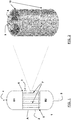
- the reactor (1) is essentially composed of a cylindrical vessel (A) and two closing elements (B1) and (B2).
- the closing elements (B1) and (B2) are respectively provided with a line (4) and a line (5) which, depending on the use of the reactor and direction of the flows, can either be for the inlet of the reagents or outlet of the reaction products.
- a line (4) and a line (5) which, depending on the use of the reactor and direction of the flows, can either be for the inlet of the reagents or outlet of the reaction products.
- the cylindrical body (A) there is also an inlet line (2) and an outlet line (3) of the thermoregulation fluid of the chemical reaction involved.
- the inlet and outlet can be inverted in relation to the desired thermal exchange mode, whether the flow is equicurrent or countercurrent with respect to the direction of the flow of reaction fluid.
- the tube-bundle is positioned inside the cylindrical vessel (A), said tube-bundle being composed of multi-structured tubular elements (7), inserted, by the respective ends, in the tube plates (6), which is represented in detail, for a single element, in the drawings of Figures 2 to 4 .
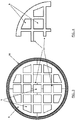
- Figure 3 shows, in the schematic view of its transversal section, some details of the tubular element (7) perspectively represented in figure 2 , before the channels present therein are possibly filled with solid catalyst.
- the four monolithic bodies (8) can be clearly seen, having a form which is approximately a fourth of the cylinder with two sides having an irregular geometry and a semicircular wall, assembled adjacently so as to form an overall compact circular cylindrical structure in which there are a plurality of square-shaped or trapezoidal cells, corresponding to the longitudinal channels (9).
- the section of the tubular element (7) is enclosed inside a circular crown which represents the section of a metallic tubular sheath (10), in which the multi-structured tubular element is preferably inserted, having the double function of contributing to maintaining the fixed position of the various monolithic bodies (8) and in any case allowing a sufficiently effective heat transfer.
- Some of the walls which separate the channels (9) from each other, close to the side edge of the section of each thermoconductive monolithic body (8), can be extended by a section, whose length is selected by the designer on the basis of usual criteria of production and assembly.
- the sections of wall are extended for a length which can be approximately equal to the side of the same channels or about half of the same, to form a structural element which can be defined in common terminology as a shelf or flap (11), suitable to correspond with the respective extensions or sections of side wall of the adjacent monolithic body(ies).
- thermoconductive monolithic bodies (8) once assembled in the multi-structured tubular element (7), form further channels (9) destined for being filled with catalyst.
- a sheathed honeycomb multi-structured tubular element made of aluminium is prepared, having a length of 1 metre with a circular section as represented in figure 3 , having an outer diameter equal to 28 mm (excluding the tubular sheath (10)) and an average cell density of 3.4 cells per square centimetre, comprising longitudinal channels (9) having a square or trapezoidal section close to the outer side surface, whose side size is about 4 mm.
- the longitudinal channels are separated by aluminium walls having a thickness of about 1.2 mm.
- the tubular element is obtained by assembling four aluminium monolithic bodies, the same as each other, each with a length of 1 m, having the section represented in figure 4 .
- Each monolithic body comprises three longitudinal channels and various flaps (11) suitably positioned along the two straight sides, as schematically represented in the section of figure 4 , so as to form additional longitudinal channels once the four monolithic bodies have been assembled to form the tubular element.
- the monolithic bodies were obtained by extruding an aluminium profile having a length of 5 metres through a head shaped according to the desired geometry of figure 4 , and then cutting the four bodies to the desired length of 1 m.
- the monolithic bodies carefully cleaned of any trace of dust and metallic shavings, were subsequently assembled by interfacing the respective orthogonal sides and externally leaving the side surface semi-cylindrical, forming a multi-structured tubular element, which was then fixed definitely by means of drawing with a steel tubular sheath having a thickness of about 3 mm.
- a stainless steel tube was prepared, having a length of 1 m, with an internal diameter of 29 mm and a thickness of 3 mm, in which the above preassembled tubular element was inserted.
- the channels of the sheathed tubular element thus obtained having an overall void fraction equal to 0.5, were filled with a catalyst for Fischer-Tropsch synthesis based on cobalt supported on alumina (in the state of oxidized precursor) in particulate form with a surface area of 80 m 2 /g, a narrow distribution, having an average diameter of 340 ⁇ m and a substantial absence of fine products with a diameter ⁇ 140 ⁇ m, whose Co content was 15% by weight.
- the catalyst was charged using a hopper having a flexible tube and applying a vibration system to favour the packing, obtaining a filling ratio of 0.60.
- the total specific productivity to hydrocarbons (C1+) of this reactor is equal to 301 kg/h/m 3 and the pressure drops are 0.14 bar.
Landscapes
- Chemical & Material Sciences (AREA)
- Oil, Petroleum & Natural Gas (AREA)
- Organic Chemistry (AREA)
- Chemical Kinetics & Catalysis (AREA)
- Engineering & Computer Science (AREA)
- General Chemical & Material Sciences (AREA)
- Physical Or Chemical Processes And Apparatus (AREA)
- Devices And Processes Conducted In The Presence Of Fluids And Solid Particles (AREA)
Claims (15)
- Ein mehrfach strukturiertes bzw. multistrukturiertes rohrförmiges Element eines Reaktors zum Bewirken exothermer/endothermer chemischer Reaktionen, wobei dieses Element Folgendes bewerkstelligt:- Aufweisen eine Länge von 10 bis 1000 mal der Hauptabmessung seines Transversalschnitts, wobei der genannte Transversalschnitt im Wesentlichen gleichförmig über die gesamte Länge des mehrfach strukturierten rohrförmigen Elements ist; und- Umfassen von zwei oder mehreren monolithischen wärmeleitenden Körpern, die sich in Längsrichtung erstrecken und die gleiche Länge wie das rohrförmige Element haben, die so zusammengefügt sind, dass jeder einen Teil der Seitenfläche aufweist, der in Kontakt mit der Seitenfläche eines oder mehrerer daran angrenzender monolithischer wärmeleitender Körper steht,wobei angrenzend bedeutet, dass die zwei oder mehreren monolithischen wärmeleitenden Körper in Längsrichtung parallel angeordnet sind und wobei
die genannten zwei oder mehreren monolithischen Körper zusammen eine thermisch verbundene Wabenstruktur bilden, die eine Vielzahl von Längskanälen enthält, die in der Lage sind, einen körnigen festen Katalysator zu enthalten, der sich von einem Ende zum anderen des genannten mehrfach strukturierten rohrförmigen Elements und im Wesentlichen parallel zueinander und zur Hauptachse desselben Elements erstreckt, und wobei jeder monolithische Körper mindestens eine Wand umfasst, die Teil der äußeren Seitenfläche des mehrfach strukturierten rohrförmigen Elements ist und 5 bis 80% dieser Fläche bildet. - Das rohrförmige Element nach Anspruch 1, das 3 bis 6 monolithische wärmeleitende Körper umfasst.
- Das rohrförmige Element nach irgendeinem der vorstehenden Ansprüche, wobei der Teil der Seitenfläche des genannten monolithischen wärmeleitenden Körpers, der mit dem oder den benachbarten Körpern in Kontakt steht, eben oder leicht gekehlt ist, während ein zweiter Teil der Seitenfläche eine Struktur aufweist, die bordartige Platten oder Laschen (shelves or flaps) umfasst.
- Das rohrförmige Element nach irgendeinem der vorstehenden Ansprüche, wobei die räumliche Dichte der Längskanäle so ist, dass der Querschnitt desselben im Durchschnitt 1 bis 50, vorzugsweise 3 bis 30 Zellen pro cm2 umfasst.
- Das rohrförmige Element nach irgendeinem der vorstehenden Ansprüche, wobei das Material, aus dem jeder wärmeleitende Körper zusammengesetzt ist, gekennzeichnet ist durch eine intrinsische Wärmeleitfähigkeit, die gleich oder höher als 10 W/m/K, vorzugsweise im Bereich von 100 bis 400 W/m/K ist bzw. liegt.
- Das rohrförmige Element nach irgendeinem der vorstehenden Ansprüche, dessen Querschnitt eine maximale Abmessung im Bereich von 10 bis 100 mm, vorzugsweise von 20 bis 50 mm, aufweist.
- Das rohrförmige Element nach irgendeinem der vorstehenden Ansprüche, das ebenfalls eine rohrförmige wärmeleitende Ummantelung umfasst, die ganz oder teilweise auf der äußeren Seitenfläche desselben angeordnet ist.
- Das rohrförmige Element nach Anspruch 7, wobei die genannte Ummantelung mittels Ziehen in engem Kontakt mit der äußeren Seitenfläche des röhrenförmigen Elements positioniert wird.
- Das rohrförmige Element nach irgendeinem der vorstehenden Ansprüche 7 oder 8, wobei die besagte Ummantelung aus Stahl oder rostfreiem Stahl hergestellt ist.
- Das rohrförmige Element nach irgendeinem der vorstehenden Ansprüche, das einen Katalysator in Form von körnigen Körpern umfasst, die in mindestens einem, vorzugsweise in jedem Längskanal angeordnet sind.
- Ein Verfahren zur Herstellung eines rohrförmigen Elements eines Reaktors nach irgendeinem der Ansprüche von 1 bis 10, umfassend die Anordnung von zwei oder mehreren monolithischen wärmeleitenden Körpern mit zwei Köpfen oder Endabschnitten, jeweils an den gegenüberliegenden Enden jedes Körpers, und einer oder mehreren Seitenflächen, die im Wesentlichen parallel zur Längsachse sind, sodass zumindest ein Teil der Seitenfläche jedes monolithischen Körpers mit der eines oder mehrerer anderer monolithischer Körper in Kontakt ist, die zusammen eine thermisch verbundene Wabenstruktur bilden, die eine Vielzahl von Längskanälen enthält, die sich von einem Ende zum anderen des genannten mehrfach bzw. multi- strukturierten rohrförmigen Elements und im Wesentlichen parallel zueinander und zur Hauptachse desselben Elements erstrecken.
- Das Verfahren nach irgendeinem der vorstehenden Ansprüche 11 oder 12, wobei der genannte eine oder die genannten mehreren monolithischen wärmeleitenden Körper mittels Extrusionstechnik hergestellt werden.
- Das Verfahren nach irgendeinem der vorstehenden Ansprüche von 11 bis 12, das ferner einen Ziehschritt umfasst, bei dem eine wärmeleitende röhrenförmige Ummantelung auf der äußeren Seitenfläche des genannten mehrfach strukturierten röhrenförmigen Elements eines Reaktors positioniert wird.
- Die Verwendung des mehrfach strukturierten rohrförmigen Elements eines Reaktors nach irgendeinem der Ansprüche von 1 bis 10 zum Bewirken exothermer oder endothermer Reaktionen.
- Ein Reaktor (1) zum Bewirken exothermer/endothermer chemischer Reaktionen, der Folgendes umfasst:(a) einen im Wesentlichen zylindrischen Behälter (A) oder mit einer ähnlichen Form, der versehen ist mit Zufuhr- und Austragsmittel (2) (3) für ein Temperaturregulierungs-Fluid der chemischen Reaktion;(b) ein oberes Verschlusselement (B1) und ein unteres Verschlusselement (B2), die jeweils am Kopf und am Boden des Behälters angeordnet sind;(c) Zufuhrmittel der Reagenzmischung, die angeordnet sind (4) im oberen Verschlusselement (B1) oder (5) im unteren Verschlusselement (B2);(d) Austragsmittel der reagierten bzw. umgesetzten Phase (reacted phase), die angeordnet sind (5) im unteren Verschlusselement oder (4) im oberen Verschlusselement;(e) mindestens ein mehrfach bzw. multi- strukturiertes rohrförmiges Element (7) nach irgendeinem der vorhergehenden Ansprüche von 1 bis 10, als solches oder ummantelt, das im Inneren des Behälters (A) zwischen dem oberen Verschlusselement (B1) und dem unteren Verschlusselement (B2) positioniert ist.
Applications Claiming Priority (2)
| Application Number | Priority Date | Filing Date | Title |
|---|---|---|---|
| IT002251A ITMI20122251A1 (it) | 2012-12-28 | 2012-12-28 | Reattore pluristrutturato per processi chimici con elevato scambio termico |
| PCT/EP2013/078083 WO2014102350A1 (en) | 2012-12-28 | 2013-12-27 | Multi-structured reactor made of monolithic adjacent thermoconductive bodies for chemical processes with a high heat exchange |
Publications (2)
| Publication Number | Publication Date |
|---|---|
| EP2938430A1 EP2938430A1 (de) | 2015-11-04 |
| EP2938430B1 true EP2938430B1 (de) | 2020-09-09 |
Family
ID=47720672
Family Applications (1)
| Application Number | Title | Priority Date | Filing Date |
|---|---|---|---|
| EP13818226.6A Active EP2938430B1 (de) | 2012-12-28 | 2013-12-27 | Multistrukturierter reaktor aus monolithischen wärmeleitenden körpern für chemische prozesse mit hohem wärmeaustausch |
Country Status (7)
| Country | Link |
|---|---|
| US (1) | US10011776B2 (de) |
| EP (1) | EP2938430B1 (de) |
| CN (1) | CN105121003A (de) |
| AU (1) | AU2013369215B2 (de) |
| IT (1) | ITMI20122251A1 (de) |
| RU (1) | RU2656482C2 (de) |
| WO (1) | WO2014102350A1 (de) |
Families Citing this family (2)
| Publication number | Priority date | Publication date | Assignee | Title |
|---|---|---|---|---|
| US10434484B1 (en) | 2019-03-29 | 2019-10-08 | Emerging Fuels Technology, Inc. | Stacked zone vertical tubular reactor |
| US11565227B2 (en) | 2021-01-27 | 2023-01-31 | Emerging Fuels Technology, Inc. | Heat transfer elements |
Family Cites Families (14)
| Publication number | Priority date | Publication date | Assignee | Title |
|---|---|---|---|---|
| GB8528031D0 (en) * | 1985-11-13 | 1985-12-18 | Ici Plc | Ceramic structures |
| US5645613A (en) | 1992-04-13 | 1997-07-08 | Rentech, Inc. | Process for the production of hydrocarbons |
| US5254840A (en) * | 1991-12-12 | 1993-10-19 | Corning Incorporated | Mounting for metal honeycomb structures |
| NO313086B1 (no) | 1995-08-04 | 2002-08-12 | Inst Francais Du Petrole | Fremgangsmåte for fremstilling av en katalysator, katalysator som kan oppnås derved, katalysatorblanding oppnådd derved samtfremgangsmåte for syntese av hydrokarboner |
| US7678343B2 (en) * | 1999-12-24 | 2010-03-16 | Ineos Vinyls Uk Ltd. | Metallic monolith catalyst support for selective gas phase reactions in tubular fixed bed reactors |
| JP2002273130A (ja) * | 2001-03-22 | 2002-09-24 | Ngk Insulators Ltd | ハニカム構造体 |
| JP4511070B2 (ja) * | 2001-03-29 | 2010-07-28 | 日本碍子株式会社 | ハニカム構造体及びそのアッセンブリ |
| JP2002292225A (ja) * | 2001-03-30 | 2002-10-08 | Ngk Insulators Ltd | ハニカム構造体及びそのアッセンブリ |
| US6881703B2 (en) * | 2001-08-08 | 2005-04-19 | Corning Incorporated | Thermally conductive honeycombs for chemical reactors |
| US20050142049A1 (en) * | 2003-12-31 | 2005-06-30 | Amsden Jeffrey M. | Multi-tubular reactors with monolithic catalysts |
| AT502666B8 (de) * | 2005-12-16 | 2007-07-15 | Porzellanfabrik Frauenthal Gmb | Verfahren und wabenkörper zum reinigen und/oder regenerieren von gasen |
| EP2006266B1 (de) * | 2006-03-23 | 2019-10-09 | NGK Insulators, Ltd. | Herstellungsverfahren einer wabenstruktur |
| ITMI20062466A1 (it) | 2006-12-21 | 2008-06-22 | Eni Spa | Reattore modulare per reazioni chimiche esotermiche-endotermiche |
| IT1394068B1 (it) | 2009-05-13 | 2012-05-25 | Milano Politecnico | Reattore per reazioni catalitiche esotermiche o endotermiche |
-
2012
- 2012-12-28 IT IT002251A patent/ITMI20122251A1/it unknown
-
2013
- 2013-12-27 CN CN201380073978.4A patent/CN105121003A/zh active Pending
- 2013-12-27 WO PCT/EP2013/078083 patent/WO2014102350A1/en not_active Ceased
- 2013-12-27 AU AU2013369215A patent/AU2013369215B2/en active Active
- 2013-12-27 RU RU2015128012A patent/RU2656482C2/ru active
- 2013-12-27 US US14/758,288 patent/US10011776B2/en active Active
- 2013-12-27 EP EP13818226.6A patent/EP2938430B1/de active Active
Non-Patent Citations (1)
| Title |
|---|
| None * |
Also Published As
| Publication number | Publication date |
|---|---|
| US20150353838A1 (en) | 2015-12-10 |
| US10011776B2 (en) | 2018-07-03 |
| EP2938430A1 (de) | 2015-11-04 |
| AU2013369215A1 (en) | 2015-07-23 |
| AU2013369215B2 (en) | 2017-06-22 |
| RU2015128012A (ru) | 2017-02-03 |
| ITMI20122251A1 (it) | 2014-06-29 |
| WO2014102350A1 (en) | 2014-07-03 |
| RU2656482C2 (ru) | 2018-06-05 |
| CN105121003A (zh) | 2015-12-02 |
Similar Documents
| Publication | Publication Date | Title |
|---|---|---|
| EP2429692B1 (de) | Reaktor für exotherme und endotherme katalytische reaktionen | |
| EP3041602B1 (de) | Rohrreaktor mit verpacktem bett für heterogene exotherme oder endotherme katalytische reaktionen | |
| CA2552283C (en) | Fischer-tropsch synthesis using microchannel technology and novel catalyst and microchannel reactor | |
| Visconti et al. | Monolithic catalysts with high thermal conductivity for the Fischer–Tropsch synthesis in tubular reactors | |
| JP2012520328A (ja) | 流体スパージ型らせん状チャンネルリアクタおよび関連する方法 | |
| KR102378451B1 (ko) | 촉매 | |
| US20070299148A1 (en) | Tubular Reactor With Packing | |
| KR20170110848A (ko) | 쉘-앤드-멀티-더블 컨센트릭-튜브 반응기 및 열교환기 | |
| CN101594929A (zh) | 用于放热/吸热化学反应的模块式反应器 | |
| EP2938430B1 (de) | Multistrukturierter reaktor aus monolithischen wärmeleitenden körpern für chemische prozesse mit hohem wärmeaustausch | |
| US9446370B2 (en) | Reactor system for producing hydrocarbons from synthetic gas | |
| US10737236B2 (en) | Structural catalyst with internal heat transfer system for exothermic and endothermic reactions | |
| Visconti et al. | Honeycomb supports with high thermal conductivity for the Tischer-Tropsch synthesis |
Legal Events
| Date | Code | Title | Description |
|---|---|---|---|
| PUAI | Public reference made under article 153(3) epc to a published international application that has entered the european phase |
Free format text: ORIGINAL CODE: 0009012 |
|
| 17P | Request for examination filed |
Effective date: 20150716 |
|
| AK | Designated contracting states |
Kind code of ref document: A1 Designated state(s): AL AT BE BG CH CY CZ DE DK EE ES FI FR GB GR HR HU IE IS IT LI LT LU LV MC MK MT NL NO PL PT RO RS SE SI SK SM TR |
|
| AX | Request for extension of the european patent |
Extension state: BA ME |
|
| DAX | Request for extension of the european patent (deleted) | ||
| STAA | Information on the status of an ep patent application or granted ep patent |
Free format text: STATUS: EXAMINATION IS IN PROGRESS |
|
| 17Q | First examination report despatched |
Effective date: 20170607 |
|
| GRAP | Despatch of communication of intention to grant a patent |
Free format text: ORIGINAL CODE: EPIDOSNIGR1 |
|
| STAA | Information on the status of an ep patent application or granted ep patent |
Free format text: STATUS: GRANT OF PATENT IS INTENDED |
|
| RIC1 | Information provided on ipc code assigned before grant |
Ipc: C10G 2/00 20060101ALI20200310BHEP Ipc: B01J 19/24 20060101AFI20200310BHEP |
|
| INTG | Intention to grant announced |
Effective date: 20200401 |
|
| GRAS | Grant fee paid |
Free format text: ORIGINAL CODE: EPIDOSNIGR3 |
|
| GRAA | (expected) grant |
Free format text: ORIGINAL CODE: 0009210 |
|
| STAA | Information on the status of an ep patent application or granted ep patent |
Free format text: STATUS: THE PATENT HAS BEEN GRANTED |
|
| AK | Designated contracting states |
Kind code of ref document: B1 Designated state(s): AL AT BE BG CH CY CZ DE DK EE ES FI FR GB GR HR HU IE IS IT LI LT LU LV MC MK MT NL NO PL PT RO RS SE SI SK SM TR |
|
| REG | Reference to a national code |
Ref country code: GB Ref legal event code: FG4D |
|
| REG | Reference to a national code |
Ref country code: AT Ref legal event code: REF Ref document number: 1310869 Country of ref document: AT Kind code of ref document: T Effective date: 20200915 Ref country code: CH Ref legal event code: EP |
|
| REG | Reference to a national code |
Ref country code: DE Ref legal event code: R096 Ref document number: 602013072434 Country of ref document: DE |
|
| REG | Reference to a national code |
Ref country code: IE Ref legal event code: FG4D |
|
| REG | Reference to a national code |
Ref country code: NO Ref legal event code: T2 Effective date: 20200909 |
|
| REG | Reference to a national code |
Ref country code: LT Ref legal event code: MG4D |
|
| PG25 | Lapsed in a contracting state [announced via postgrant information from national office to epo] |
Ref country code: LT Free format text: LAPSE BECAUSE OF FAILURE TO SUBMIT A TRANSLATION OF THE DESCRIPTION OR TO PAY THE FEE WITHIN THE PRESCRIBED TIME-LIMIT Effective date: 20200909 Ref country code: BG Free format text: LAPSE BECAUSE OF FAILURE TO SUBMIT A TRANSLATION OF THE DESCRIPTION OR TO PAY THE FEE WITHIN THE PRESCRIBED TIME-LIMIT Effective date: 20201209 Ref country code: HR Free format text: LAPSE BECAUSE OF FAILURE TO SUBMIT A TRANSLATION OF THE DESCRIPTION OR TO PAY THE FEE WITHIN THE PRESCRIBED TIME-LIMIT Effective date: 20200909 Ref country code: GR Free format text: LAPSE BECAUSE OF FAILURE TO SUBMIT A TRANSLATION OF THE DESCRIPTION OR TO PAY THE FEE WITHIN THE PRESCRIBED TIME-LIMIT Effective date: 20201210 Ref country code: FI Free format text: LAPSE BECAUSE OF FAILURE TO SUBMIT A TRANSLATION OF THE DESCRIPTION OR TO PAY THE FEE WITHIN THE PRESCRIBED TIME-LIMIT Effective date: 20200909 Ref country code: SE Free format text: LAPSE BECAUSE OF FAILURE TO SUBMIT A TRANSLATION OF THE DESCRIPTION OR TO PAY THE FEE WITHIN THE PRESCRIBED TIME-LIMIT Effective date: 20200909 |
|
| REG | Reference to a national code |
Ref country code: AT Ref legal event code: MK05 Ref document number: 1310869 Country of ref document: AT Kind code of ref document: T Effective date: 20200909 |
|
| REG | Reference to a national code |
Ref country code: NL Ref legal event code: MP Effective date: 20200909 |
|
| PG25 | Lapsed in a contracting state [announced via postgrant information from national office to epo] |
Ref country code: RS Free format text: LAPSE BECAUSE OF FAILURE TO SUBMIT A TRANSLATION OF THE DESCRIPTION OR TO PAY THE FEE WITHIN THE PRESCRIBED TIME-LIMIT Effective date: 20200909 Ref country code: PL Free format text: LAPSE BECAUSE OF FAILURE TO SUBMIT A TRANSLATION OF THE DESCRIPTION OR TO PAY THE FEE WITHIN THE PRESCRIBED TIME-LIMIT Effective date: 20200909 Ref country code: LV Free format text: LAPSE BECAUSE OF FAILURE TO SUBMIT A TRANSLATION OF THE DESCRIPTION OR TO PAY THE FEE WITHIN THE PRESCRIBED TIME-LIMIT Effective date: 20200909 |
|
| PG25 | Lapsed in a contracting state [announced via postgrant information from national office to epo] |
Ref country code: CZ Free format text: LAPSE BECAUSE OF FAILURE TO SUBMIT A TRANSLATION OF THE DESCRIPTION OR TO PAY THE FEE WITHIN THE PRESCRIBED TIME-LIMIT Effective date: 20200909 Ref country code: EE Free format text: LAPSE BECAUSE OF FAILURE TO SUBMIT A TRANSLATION OF THE DESCRIPTION OR TO PAY THE FEE WITHIN THE PRESCRIBED TIME-LIMIT Effective date: 20200909 Ref country code: PT Free format text: LAPSE BECAUSE OF FAILURE TO SUBMIT A TRANSLATION OF THE DESCRIPTION OR TO PAY THE FEE WITHIN THE PRESCRIBED TIME-LIMIT Effective date: 20210111 Ref country code: NL Free format text: LAPSE BECAUSE OF FAILURE TO SUBMIT A TRANSLATION OF THE DESCRIPTION OR TO PAY THE FEE WITHIN THE PRESCRIBED TIME-LIMIT Effective date: 20200909 Ref country code: RO Free format text: LAPSE BECAUSE OF FAILURE TO SUBMIT A TRANSLATION OF THE DESCRIPTION OR TO PAY THE FEE WITHIN THE PRESCRIBED TIME-LIMIT Effective date: 20200909 Ref country code: SM Free format text: LAPSE BECAUSE OF FAILURE TO SUBMIT A TRANSLATION OF THE DESCRIPTION OR TO PAY THE FEE WITHIN THE PRESCRIBED TIME-LIMIT Effective date: 20200909 |
|
| PG25 | Lapsed in a contracting state [announced via postgrant information from national office to epo] |
Ref country code: ES Free format text: LAPSE BECAUSE OF FAILURE TO SUBMIT A TRANSLATION OF THE DESCRIPTION OR TO PAY THE FEE WITHIN THE PRESCRIBED TIME-LIMIT Effective date: 20200909 Ref country code: AT Free format text: LAPSE BECAUSE OF FAILURE TO SUBMIT A TRANSLATION OF THE DESCRIPTION OR TO PAY THE FEE WITHIN THE PRESCRIBED TIME-LIMIT Effective date: 20200909 Ref country code: AL Free format text: LAPSE BECAUSE OF FAILURE TO SUBMIT A TRANSLATION OF THE DESCRIPTION OR TO PAY THE FEE WITHIN THE PRESCRIBED TIME-LIMIT Effective date: 20200909 Ref country code: IS Free format text: LAPSE BECAUSE OF FAILURE TO SUBMIT A TRANSLATION OF THE DESCRIPTION OR TO PAY THE FEE WITHIN THE PRESCRIBED TIME-LIMIT Effective date: 20210109 |
|
| REG | Reference to a national code |
Ref country code: DE Ref legal event code: R097 Ref document number: 602013072434 Country of ref document: DE |
|
| PG25 | Lapsed in a contracting state [announced via postgrant information from national office to epo] |
Ref country code: SK Free format text: LAPSE BECAUSE OF FAILURE TO SUBMIT A TRANSLATION OF THE DESCRIPTION OR TO PAY THE FEE WITHIN THE PRESCRIBED TIME-LIMIT Effective date: 20200909 |
|
| PLBE | No opposition filed within time limit |
Free format text: ORIGINAL CODE: 0009261 |
|
| STAA | Information on the status of an ep patent application or granted ep patent |
Free format text: STATUS: NO OPPOSITION FILED WITHIN TIME LIMIT |
|
| REG | Reference to a national code |
Ref country code: CH Ref legal event code: PL |
|
| 26N | No opposition filed |
Effective date: 20210610 |
|
| PG25 | Lapsed in a contracting state [announced via postgrant information from national office to epo] |
Ref country code: SI Free format text: LAPSE BECAUSE OF FAILURE TO SUBMIT A TRANSLATION OF THE DESCRIPTION OR TO PAY THE FEE WITHIN THE PRESCRIBED TIME-LIMIT Effective date: 20200909 Ref country code: DK Free format text: LAPSE BECAUSE OF FAILURE TO SUBMIT A TRANSLATION OF THE DESCRIPTION OR TO PAY THE FEE WITHIN THE PRESCRIBED TIME-LIMIT Effective date: 20200909 Ref country code: MC Free format text: LAPSE BECAUSE OF FAILURE TO SUBMIT A TRANSLATION OF THE DESCRIPTION OR TO PAY THE FEE WITHIN THE PRESCRIBED TIME-LIMIT Effective date: 20200909 |
|
| REG | Reference to a national code |
Ref country code: BE Ref legal event code: MM Effective date: 20201231 |
|
| PG25 | Lapsed in a contracting state [announced via postgrant information from national office to epo] |
Ref country code: LU Free format text: LAPSE BECAUSE OF NON-PAYMENT OF DUE FEES Effective date: 20201227 Ref country code: IE Free format text: LAPSE BECAUSE OF NON-PAYMENT OF DUE FEES Effective date: 20201227 |
|
| PG25 | Lapsed in a contracting state [announced via postgrant information from national office to epo] |
Ref country code: LI Free format text: LAPSE BECAUSE OF NON-PAYMENT OF DUE FEES Effective date: 20201231 Ref country code: CH Free format text: LAPSE BECAUSE OF NON-PAYMENT OF DUE FEES Effective date: 20201231 |
|
| PG25 | Lapsed in a contracting state [announced via postgrant information from national office to epo] |
Ref country code: TR Free format text: LAPSE BECAUSE OF FAILURE TO SUBMIT A TRANSLATION OF THE DESCRIPTION OR TO PAY THE FEE WITHIN THE PRESCRIBED TIME-LIMIT Effective date: 20200909 Ref country code: MT Free format text: LAPSE BECAUSE OF FAILURE TO SUBMIT A TRANSLATION OF THE DESCRIPTION OR TO PAY THE FEE WITHIN THE PRESCRIBED TIME-LIMIT Effective date: 20200909 Ref country code: CY Free format text: LAPSE BECAUSE OF FAILURE TO SUBMIT A TRANSLATION OF THE DESCRIPTION OR TO PAY THE FEE WITHIN THE PRESCRIBED TIME-LIMIT Effective date: 20200909 |
|
| PG25 | Lapsed in a contracting state [announced via postgrant information from national office to epo] |
Ref country code: MK Free format text: LAPSE BECAUSE OF FAILURE TO SUBMIT A TRANSLATION OF THE DESCRIPTION OR TO PAY THE FEE WITHIN THE PRESCRIBED TIME-LIMIT Effective date: 20200909 |
|
| PG25 | Lapsed in a contracting state [announced via postgrant information from national office to epo] |
Ref country code: BE Free format text: LAPSE BECAUSE OF NON-PAYMENT OF DUE FEES Effective date: 20201231 |
|
| P01 | Opt-out of the competence of the unified patent court (upc) registered |
Effective date: 20230804 |
|
| PGFP | Annual fee paid to national office [announced via postgrant information from national office to epo] |
Ref country code: GB Payment date: 20251229 Year of fee payment: 13 |
|
| PGFP | Annual fee paid to national office [announced via postgrant information from national office to epo] |
Ref country code: NO Payment date: 20251231 Year of fee payment: 13 |
|
| PGFP | Annual fee paid to national office [announced via postgrant information from national office to epo] |
Ref country code: IT Payment date: 20251219 Year of fee payment: 13 |
|
| PGFP | Annual fee paid to national office [announced via postgrant information from national office to epo] |
Ref country code: FR Payment date: 20251226 Year of fee payment: 13 |
|
| PGFP | Annual fee paid to national office [announced via postgrant information from national office to epo] |
Ref country code: DE Payment date: 20251229 Year of fee payment: 13 |