EP2937701A1 - Grenzschichtdurchflusssensor - Google Patents
Grenzschichtdurchflusssensor Download PDFInfo
- Publication number
- EP2937701A1 EP2937701A1 EP15157613.9A EP15157613A EP2937701A1 EP 2937701 A1 EP2937701 A1 EP 2937701A1 EP 15157613 A EP15157613 A EP 15157613A EP 2937701 A1 EP2937701 A1 EP 2937701A1
- Authority
- EP
- European Patent Office
- Prior art keywords
- boundary layer
- flow sensor
- pressure
- layer flow
- pressure tube
- Prior art date
- Legal status (The legal status is an assumption and is not a legal conclusion. Google has not performed a legal analysis and makes no representation as to the accuracy of the status listed.)
- Granted
Links
Images





Classifications
-
- G—PHYSICS
- G01—MEASURING; TESTING
- G01M—TESTING STATIC OR DYNAMIC BALANCE OF MACHINES OR STRUCTURES; TESTING OF STRUCTURES OR APPARATUS, NOT OTHERWISE PROVIDED FOR
- G01M9/00—Aerodynamic testing; Arrangements in or on wind tunnels
- G01M9/06—Measuring arrangements specially adapted for aerodynamic testing
- G01M9/065—Measuring arrangements specially adapted for aerodynamic testing dealing with flow
-
- G—PHYSICS
- G01—MEASURING; TESTING
- G01P—MEASURING LINEAR OR ANGULAR SPEED, ACCELERATION, DECELERATION, OR SHOCK; INDICATING PRESENCE, ABSENCE, OR DIRECTION, OF MOVEMENT
- G01P5/00—Measuring speed of fluids, e.g. of air stream; Measuring speed of bodies relative to fluids, e.g. of ship, of aircraft
- G01P5/14—Measuring speed of fluids, e.g. of air stream; Measuring speed of bodies relative to fluids, e.g. of ship, of aircraft by measuring differences of pressure in the fluid
-
- B—PERFORMING OPERATIONS; TRANSPORTING
- B64—AIRCRAFT; AVIATION; COSMONAUTICS
- B64D—EQUIPMENT FOR FITTING IN OR TO AIRCRAFT; FLIGHT SUITS; PARACHUTES; ARRANGEMENT OR MOUNTING OF POWER PLANTS OR PROPULSION TRANSMISSIONS IN AIRCRAFT
- B64D43/00—Arrangements or adaptations of instruments
-
- G—PHYSICS
- G01—MEASURING; TESTING
- G01K—MEASURING TEMPERATURE; MEASURING QUANTITY OF HEAT; THERMALLY-SENSITIVE ELEMENTS NOT OTHERWISE PROVIDED FOR
- G01K5/00—Measuring temperature based on the expansion or contraction of a material
- G01K5/28—Measuring temperature based on the expansion or contraction of a material the material being a gas
-
- G—PHYSICS
- G01—MEASURING; TESTING
- G01P—MEASURING LINEAR OR ANGULAR SPEED, ACCELERATION, DECELERATION, OR SHOCK; INDICATING PRESENCE, ABSENCE, OR DIRECTION, OF MOVEMENT
- G01P13/00—Indicating or recording presence, absence, or direction, of movement
- G01P13/02—Indicating direction only, e.g. by weather vane
- G01P13/025—Indicating direction only, e.g. by weather vane indicating air data, i.e. flight variables of an aircraft, e.g. angle of attack, side slip, shear, yaw
-
- G—PHYSICS
- G01—MEASURING; TESTING
- G01P—MEASURING LINEAR OR ANGULAR SPEED, ACCELERATION, DECELERATION, OR SHOCK; INDICATING PRESENCE, ABSENCE, OR DIRECTION, OF MOVEMENT
- G01P5/00—Measuring speed of fluids, e.g. of air stream; Measuring speed of bodies relative to fluids, e.g. of ship, of aircraft
- G01P5/14—Measuring speed of fluids, e.g. of air stream; Measuring speed of bodies relative to fluids, e.g. of ship, of aircraft by measuring differences of pressure in the fluid
- G01P5/16—Measuring speed of fluids, e.g. of air stream; Measuring speed of bodies relative to fluids, e.g. of ship, of aircraft by measuring differences of pressure in the fluid using Pitot tubes, e.g. Machmeter
- G01P5/165—Arrangements or constructions of Pitot tubes
Definitions
- Ambient airflow over an aerodynamic surface creates a boundary layer at the surface over which it flows.
- the airflow at the aerodynamic surface may be thought of as having zero velocity at the precise location abutting the surface due to the viscosity at the surface, speeding up to the mean velocity of the ambient airflow at a distance from the surface.
- the airflow within this distance defines the boundary layer.
- the airflow within a boundary layer may be generally characterized as laminar or turbulent.
- Laminar flow is generally associated with lower skin friction, lower flow velocity near the surface, and thinner boundary layer thickness as compared with turbulent flow. As a result, laminar flow is often desirable in order to reduce aerodynamic drag.
- Determining whether an airflow is laminar or turbulent may be done in various ways, each of which is undesirable for various reasons.
- Conventional techniques include using an infrared camera to measure surface temperature, using a hot film to measure sheer stress, or using a pressure tube mounted on the surface to measure the total pressure of the airflow. These techniques are often cumbersome, not practical for routine flight operations, not useful in all desired locations, and create additional drag while lacking the robustness needed for continued use in actual flight operations.
- a boundary layer flow sensor includes a body, a pressure port, and an activation mechanism.
- the body is configured for mounting below an aerodynamic surface and has a pressure tube extending along a longitudinal axis of the body.
- the pressure port is configurable between an open state and a closed state. In the open state, the pressure tube is fluidly coupled to a lower portion of a boundary layer of the ambient airflow over the aerodynamic surface. In the closed state, the pressure tube is decoupled from the boundary layer.
- a boundary layer flow sensor includes a body configured for mounting within a fastener aperture within an aerodynamic surface, and an activation mechanism.
- the body includes a movable shaft that is moveable between a raised position to create an open state for a pressure port and a lowered position to create a closed state for the pressure port. In the closed state, the body is substantially flush with the aerodynamic surface.
- the moveable shaft includes a total pressure tube extending along a longitudinal axis of the movable shaft and is substantially aligned with the ambient airflow when the pressure port is in the open state.
- the moveable shaft also includes at least one static pressure tube positioned at an offset angle from the total pressure tube.
- the activation mechanism is operative to raise the moveable shaft and fluidly couple the total pressure tube and the static pressure tube to a lower portion of a boundary layer of the ambient airflow, and to lower the movable shaft to the lowered position substantially flush with the aerodynamic surface and fluidly decouple the total pressure tube and the static pressure tube from the lower portion of the boundary layer of the ambient airflow.
- a method for determining flow characteristics of an ambient airflow over an aerodynamic surface includes activating a boundary layer flow sensor that is mounted substantially flush with the aerodynamic surface. In response to activation, a pressure port is exposed to a lower portion of a boundary layer of the ambient airflow. At least one pressure is measured within the ambient airflow and used to determine whether the ambient airflow is substantially laminar or turbulent.
- the boundary layer flow sensor described herein may be used to determine laminar or turbulent flow conditions associated with an aerodynamic surface. As discussed briefly above, it is often useful to determining whether an airflow is laminar or turbulent over a particular aerodynamic surface or at a particular location on the surface. This determination may be useful in testing situations, such as during wind-tunnel or flight testing of a particular aircraft component, or during actual flight operations of an aircraft.
- Conventional techniques for determining laminar or turbulent flow include using an infrared camera to measure surface temperature, using a hot film to measure sheer stress, or using a pressure tube mounted on the surface to measure the total pressure of the airflow.
- an infrared camera technique With respect to the infrared camera technique, the difference between heat transfer properties of laminar and turbulent airflows, a temperature gradient at the transition location may be seen with an infrared camera.
- this technique is not practical in many situations, such as use during flight operations or to determine the airflow characteristics at a location that is not readily visible.
- Hot film may be embedded in a layer on the aerodynamic surface and used to measure sheer stress based on the heat transfer in the location of the film. The fluctuation content associated with that measurement may be used to determine the characteristics of the airflow.
- the hot film is not very durable, requiring special care. As a result, this method for determining the airflow characteristics is not ideally suited for flight operations.
- Pressure tubes mounted to an aerodynamic surface provide an accurate measure of the total pressure of the airflow directed into the tubes. This pressure may be used to determine a velocity gradient of the airflow within the boundary layer. Because the velocity gradient at the surface associated with a turbulent boundary layer is characteristically higher than the velocity gradient of the same airflow in a laminar boundary layer, the state of the airflow may be determined as being laminar or turbulent at the location of the pressure tube.
- a problem with these types of conventional measurements using pressure tubes is that the tubes are mounted externally to the aerodynamic surface, which creates drag and is not practical for flight operations. Additionally, forward facing pressure tubes may get contaminated by foreign objects such as grit, dirt, ice, water, or other particles in the environment and ambient airflow, or induced by the environment due to changes in temperature or pressure.
- a boundary layer flow sensor may be mounted within an aerodynamic surface and transitioned between open and closed states.
- a pressure port In the open state, a pressure port is exposed to a lower portion of the boundary layer of an ambient airflow in order to measure total pressure, as well as static pressure according to some embodiments.
- the pressure port In the closed state, the pressure port is decoupled from the ambient airflow such that the sensor is substantially flush with the aerodynamic surface to allow for laminar airflow and to prevent contamination of the pressure port.
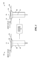
- FIGURE 1 a boundary layer flow sensor 102 is shown according to one embodiment.
- the boundary layer flow sensor 102 is shown according to two operational states, a closed state 112 and an open state 116.
- the boundary layer flow sensor 102 may be selectively re-configured between the closed state 112 and the open state 116 via an activation mechanism 114 during flight operations or testing of an aircraft in which the boundary layer flow sensor 102 is mounted.
- the activation mechanism will be described in detail below with respect to FIGURE 8 .
- the boundary layer flow sensor 102 may be effectively utilized to measure pressures within the ambient airflow over an aerodynamic surface 104 when desired, while protecting the boundary layer flow sensor 102 from contaminants and preventing disruption of the ambient airflow when not used to acquire pressure measurements.
- the boundary layer flow sensor 102 includes a body 106 mounted within or below the aerodynamic surface 104.
- the aerodynamic surface 104 may be an aircraft wing, flight control surface, stabilizer, fuselage or any surface over which an ambient airflow moves and in which it is desirable to determine whether that airflow is laminar or turbulent.
- the body 106 is mounted in a position such that the boundary layer flow sensor 102 is substantially flush with the aerodynamic surface 104. While this embodiment shows a top surface of the boundary layer flow sensor 102 that is substantially coplanar with the aerodynamic surface 104, other embodiments described herein may include a lid or other component that slightly projects above the aerodynamic surface 104.
- substantially flush may include coplanar arrangements as well as projections above the aerodynamic surface 104.
- the top surface of the boundary layer flow sensor 102, the body 106, the lid or moveable cover of the boundary layer flow sensor 102, the fastener in which a moveable shaft of the boundary layer flow sensor 102 is positioned, or any combination of these components may be countersunk within the aerodynamic surface 104.
- the body 106 may be formed from a fastener that is typically used on the aerodynamic surface 104 that has been hollowed to accommodate the components of the boundary layer flow sensor 102.
- the body 106 may be sized according to a typical fastener so that the boundary layer flow sensor 102 may be mounted within a fastener aperture that already exists in the aerodynamic surface 104.
- apertures may be incorporated into any portion of the aerodynamic surface 104 in which it would be desirable to have a boundary layer flow sensor 102 mounted within.
- the boundary layer flow sensor 102 of FIGURE 1 has a pressure tube 110 extending along a longitudinal axis of the body 106.
- the pressure tube 110 provides a pathway for the ambient airflow captured at the pressure port 118 to a pressure transducer or to an associated tube leading to pressure transducer, as will be described in greater detail below with respect to FIGURE 5B .
- the pressure port 118 is created when the activation mechanism triggers the boundary layer flow sensor 102 to transition from the closed state 112 to the open state 116.
- the open state 116 fluidly couples the pressure tube 110 to a lower portion of a boundary layer of an ambient airflow over the aerodynamic surface 104, and the closed state 112 decouples the pressure tube 110 from the boundary layer.
- the pressure port 118 may be considered the opening that couples the pressure tube 110 to the ambient airflow, allowing the associated air pressure to be measured.
- the boundary layer flow sensor 102 is re-configurable between the closed state 112 and the open state 116 to selectively protect and expose the pressure port 118.
- various embodiments will be described to provide various mechanisms for providing the closed state 112 and the open state 116, along with corresponding variations in the configuration of the pressure port 118.
- the boundary layer flow sensor 102 includes a body 106 that is fixed within or below the aerodynamic surface 104, and a movable cover 108.
- the moveable cover 108 in this example includes a hinged cover 118 that pivots from a rear edge, extending the front edge of the hinged cover 118 upwards to create an air scoop, or opening, which couples the pressure tube 110 to the ambient airflow to create the pressure port 118. As shown, the ambient airflow stream moves across the hinged cover 118, where the hinged cover 118 is configured to pivot along a downstream edge.
- the boundary layer flow sensor 102 is similar to the sensor described with respect to FIGURE 1 , including the transition between the closed state 112 and the open state 116 utilizing a moveable cover 108.
- the moveable cover 108 includes a deformable cover 218. The deformable cover buckles outward or other wise deforms from a substantially planar configuration represented by the closed state 112 to a curved, bent, or otherwise buckled configuration shown with respect to the open state 116.
- the activation mechanism 114 for providing the transition between the closed state 112 and the open state 116 may include the use of a shape memory allow within the deformable cover 218 that is configure to deform to create the open state 116 according to a threshold temperature, or may include a metal or material manufactured with an internal bias or torque that may be "popped" to the deformed configuration to create the open state 116 utilizing a relatively small mechanical force that may be triggered electrically or via a diaphragm or other pressure or temperature sensitive mechanism.
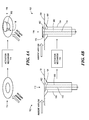
- FIGURES 3A and 3B show top perspective and side views, respectively, of a boundary layer flow sensor 102 in a closed state 112 and an open state 116 according to another embodiment.
- the boundary layer flow sensor 102 includes a movable shaft 302 positioned within the body 106.
- the activation mechanism 114 may be responsive to an ambient condition, such as temperature or pressure, or to a control input or predetermined condition or action to transition the boundary layer flow sensor 102 between the closed state 112 and the open state 116.
- the movable shaft 302 is raised from within or below the aerodynamic surface 104 to create the pressure port 118 by exposing the pressure tube 110 to the ambient airflow.
- the body 106 of this embodiment may include a fastener that has been hollowed out or otherwise configured to accept the moveable shaft 302. Consequently, the moveable shaft 302 may be sized according to a particular fastener in which it is to be positioned.
- FIGURES 4A and 4B show a similar embodiment in which the top portion 402 of the moveable shaft 302 is substantially conically shaped to compliment and nest within a conically shaped recess 404 of the body 106 when configured in the closed state 112. In doing so, the pressure tube 110 is better sealed when closed, providing better protection.
- FIGURES 5A and 5B show top perspective and side views, respectively, of an alternative embodiment of a boundary layer flow sensor 102 in a closed state 112 and an open state 116.
- the boundary layer flow sensor 102 has a moveable shaft 302 that raises and lowers to selectively expose or close the pressure port 118.
- the boundary layer flow sensor 102 of this example includes a lid 502 attached to the movable shaft 302.
- the lid 502 may be substantially flush with the aerodynamic surface 104.
- the thickness of the lid 502 may be sufficiently thin as to allow for laminar airflow over the lid 502 and the aerodynamic surface 104 without triggering a transition to turbulent airflow. For some implementations, this thickness may be less than 0.01 inches.
- an advantage provided by the lid 502 is that it may provide additional protection for the moveable shaft 302 from contamination entering the space around the moveable shaft 302 within the body 106.
- one embodiment utilizes an o-ring 504 to provide a watertight seal between the lid 502 and the top surface of the boundary layer flow sensor 102 when configured in the closed state 112.
- an o-ring 504 or other seal may be utilized with any embodiment utilizing a moveable shaft 302.
- the o-ring 504 may be fitted into the body 106 surrounding the moveable shaft 302.
- a shallow recess in the body 106 may be utilized to further enhance the seal when closed. This may also assist in providing a sufficiently thin lid for preserving laminar flow.
- FIGURES 5A and 5B also illustrate two different embodiments for converting the air pressure within the pressure port 118 to a pressure measurement to be used in the determination of the ambient airflow characteristics.
- a pressure transducer is conventionally used.
- FIGURE 5A shows a local transducer 506 that is coupled to the pressure tube 110 via a direct connection with the body 106 or moveable shaft 302.
- FIGURE 5B shows an external transducer 508 that is coupled to the pressure tube 110 via a transducer tube 510.
- the transducer tube 510 is simply a tube that fluidly connects the pressure tube 110 to the external transducer 508 located in a separate location from the boundary layer flow sensor 102.
- the local transducer 506 may provide a more compact solution as only electrical signals are transported away from the boundary layer flow sensor 102.
- the external transducer 508 may include a number of transducer tubes 510 from a number of boundary layer flow sensors 102 to feed into one or more multi-channel transducers located at a central location. The disclosure herein is not limited to any particular type of pressure transducer.
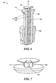
- FIGURE 6 shows a cross-sectional view of a boundary layer flow sensor 102 according to one embodiment.
- the boundary layer flow sensor 102 includes a moveable shaft 302 with a lid 502.
- This example illustrates a securing mechanism 606 positioned on the inside of the aircraft wing or other component housing the boundary layer flow sensor 102, on an opposite side of the aerodynamic surface 104, and is used to secure the body 106 in place.
- the securing mechanism 606 may be threaded and in conjunction with the body 106, may operate like a nut and bolt to hold the boundary layer flow sensor 102 in place within or below the aerodynamic surface.
- any type of securing mechanism may be used, including but not limited to inducing deformation in the body 106 during installation to hold the body 106 in place (similar to a rivet), tabs on the body 106 that engage the aerodynamic surface 104, or the like.
- the boundary layer flow sensor 102 in this example is configured to not only measure the total pressure, but also the static pressure within the lower portion of the boundary layer of the ambient airflow.
- the pressure tube 110 in the embodiments described above with respect to FIGURES 1-5 is configured to measure total pressure of the ambient airflow within the lower portion of the boundary layer.
- the pressure tubes 110 include a total pressure tube 602 configured to measure the total pressure of the ambient airflow within the lower portion of the boundary layer and at least one static pressure tube 604 configured to measure the static pressure within the lower portion of the boundary layer.
- each static pressure tube 604 is positioned along the longitudinal axis of the body 106 such that when the pressure port 118 is configured in the open state 116, the static pressure tube 604 is fluidly coupled to the lower portion of the boundary layer.
- the boundary layer flow sensor 102 includes a total pressure tube 602 and two static pressure tubes 604 positioned at offset angles 702 of approximately 60 degrees in both directions from the total pressure tube 602. While the example shown in FIGURE 6 may include two static pressure tubes 604, the second static pressure tube 604 is not visible behind the total pressure tube 602 according to that view.
- FIGURE 7 shows a top perspective view of the top portion of the boundary layer flow sensor 102 of FIGURE 6 . The boundary layer flow sensor 102 is rotated in the view shown in FIGURE 7 so that the total pressure tube 602 is facing directly outward into the ambient airflow, which would be flowing into the page.
- the boundary layer flow sensor 102 has two static pressure tubes 604 positioned at offset angles 702 from either side of the total pressure tube 602.
- the offset angles 702 may be approximately 60 degrees as measured from the position of the total pressure tube 602. According to other embodiments, the offset angles 702 may include angles within the range of 40-70 degrees from the position of the total pressure tube 602. It should be appreciated that the disclosure herein contemplates any offset angle 702 that provides for a static pressure measurement to be taken, without being limited to any particular offset angle value.
- the two static pressure tubes 604 feed into the same chamber (not shown) and allow for an average to be taken to improve accuracy of the static pressure measurement.
- FIGURE 8 is a block diagram illustrating various embodiments of an activation mechanism 114 according to the disclosure provided above.
- the activation mechanism 114 provides the transition between the closed state 112 and the open state 116 of the boundary layer flow sensor 102.
- Each of the embodiments described above with respect to FIGURES 1-7 may use one or more of various types of activation mechanisms 114.
- FIGURE 8 shows various contemplated activation mechanisms 114 presented according to the type of trigger 802 to which the activation mechanism 114 is responsive to transition the boundary layer flow sensor 102 between the closed state 112 and the open state 116.
- the triggers 802 may be generally considered as being an ambient condition or an electrical or other type of selectable or preprogrammed switch.
- An ambient condition may include a temperature threshold or a pressure threshold.
- An example of an activation mechanism 114 responsive to a temperature threshold is a shape memory alloy 804.
- Shape memory alloys 804 predictably change shape in response to being exposed to a particular temperature threshold. After transitioning back through that temperature threshold, the shape memory alloys 804 will return to their original shape. In the context of this disclosure, shape memory alloys 804 may be utilized in at least two ways.
- the deformable cover 218 described above with respect to FIGURE 2 may be manufactured from a shape memory alloy 804 that is shaped to provide the closed state 112 at temperatures above a predetermined threshold, and in response to the ambient temperature dropping below the threshold temperature, the shape memory alloy 804 used in the deformable cover 218 will change shape to create the open state 116 shown and described above.
- a shape memory alloy 804 may be used in the context of this disclosure is to be directly or indirectly attached to the moveable shaft 302.
- the shape memory alloy 804 deforms to apply a force or pressure against the moveable shaft 302 to raise the shaft and create the pressure port 118 in the open state 116.
- An increase in temperature beyond the threshold temperature would return the shape memory alloy to its original shape, which would in turn lower the moveable shaft 302, closing the pressure port 118 and creating the closed state 112.
- This concept may also be applied to providing the movement of the hinged cover 118.
- the activation mechanism 114 may also be responsive to a pressure threshold as a trigger 802 to open or close the boundary layer flow sensor 102.
- An example implementation includes utilization of a diaphragm 806 that expands and contracts in response to a decrease of ambient air pressure as altitude increases, and a corresponding increase of ambient air pressure as altitude decreases. The expansion and contraction of the diaphragm 806 may be used to physically push and pull the moveable shaft 302, as well as the hinged cover 118, to transition the pressure port 118 between the closed state 112 and the open state 116.
- the trigger 802 for the activation mechanism 114 may include an electrical or other type of selectable or preprogrammed switch.
- a pilot or other crew member or engineer may press a physical or virtual button to selectively activate and deactivate the boundary layer flow sensor 102 to transition the sensor to the open state 116 and back to the closed state 112, respectively.
- an aircraft system and associated controller may be programmed to activate and deactivate the boundary layer flow sensor 102 when a predetermined condition is satisfied.
- the predetermined condition may depend on the location of the particular boundary layer flow sensor 102 and on the timing and/or position associated with a desired laminar or turbulent airflow determination.
- the activation mechanism 114 may be programmed to create the open state 116 at a particular altitude, attitude, angle of attack, velocity, engine setting, flight control setting, stage of flight, or ambient condition such as temperature or pressure.
- a trigger 802 that is electrical or other may include a number of types of actuators 808. Examples include, but are not limited to, electro-mechanical actuators 810, piezo-electric actuators 812, solenoids 814, and any others 816. It should be understood that while multiple activation mechanisms 114 having a trigger 802 that is electrical, any other type of trigger 802 may also be used without departing from the scope of this disclosure. Examples of other types of selectable or preprogrammed triggers and corresponding actuators 808 may include, but are not limited to, hydraulic, pneumatic, and magnetic.
- the routine 900 begins at operation 902, where a boundary layer flow sensor 102 that is mounted substantially flush with the aerodynamic surface 104 is activated. As described in detail above with respect to FIGURES 8 , the activation mechanism 114 for activating the boundary layer flow sensor 102 may be triggered in various ways, including in response to ambient conditions or in response to an electrical or other selectable or preprogrammed switch.
- the routine 900 continues to operation 904, where in response to activating the boundary layer flow sensor 102, the activation mechanism 114 exposes the pressure port 118 within the lower portion of the boundary layer of the ambient airflow.
- This operation represents the transition from the closed state 112 to the open state 116, which may include the opening of the moveable cover 108 or the raising of the moveable shaft 302.
- the routine 900 continues from operation 904 to operation 906, where a pressure measurement is taken within the lower portion of the boundary layer.
- This pressure measurement is taken with the pressure tube 110, including at least a total pressure tube 602, and according to one embodiment, two static pressure tubes 604 positioned at offset angles 702 of approximately 60 degrees in both directions from the total pressure tube 602.
- a determination is made from the pressure measurement whether the ambient airflow is substantially laminar or turbulent, and the routine 900 ends.
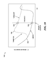
- FIGURE 10 shows a graph 1000 illustrating a pressure parameter, p*, versus distance along a chord, x/c, for both laminar and turbulent flows.
- the distance along the chord, x/c represents locations along the aerodynamic surface 104 from a position upstream of the boundary layer flow sensor 102 to a position downstream of the boundary layer flow sensor 102.
- the position of the boundary layer flow sensor 102 represented by the vertical line labeled "sensor location,” may be any position of interest in which a determination of laminar or turbulent flow is desired.
- the pressure parameter, p* represents a variable that correlates to the difference between total pressure and static pressure, normalized by a free-stream reference dynamic pressure.
- the solid line representing the laminar plot 1002 corresponds to the plot of the pressure parameter of a laminar airflow within the lower portion of a boundary layer from a position x/c upstream of the boundary layer flow sensor 102 to a position x/c downstream of the boundary layer flow sensor 102.
- the broken line representing the turbulent plot 1004 corresponds to the plot of the pressure parameter of a turbulent airflow within the lower portion of the boundary layer from a position x/c upstream of the boundary layer flow sensor 102 to a position x/c downstream of the boundary layer flow sensor 102.
- the velocity gradient at the surface for a turbulent flow is higher than that of a corresponding laminar flow.
- the pressure parameter, p* is higher for turbulent flow as compared to laminar flow.
- the transition from laminar flow to turbulent flow is identified on the graph 1000 with a "transition" label and arrow pointing to the steep increase in the turbulent plot 1004 upstream of the boundary layer flow sensor 102.
- the pressure parameter associated with a turbulent flow is identified with a turbulent pressure parameter 1006, while the pressure parameter associated with a laminar flow is identified with a laminar pressure parameter 1008.
- the boundary layer flow sensor 102 is activated to take one or more pressure measurements within the lower portion of the boundary layer of the airflow at the desired location.
- the boundary layer flow sensor 102 includes both a total pressure tube 602 and static pressure tubes 604, measurements of total pressure, P t , and of static pressure, P s , may be taken and used to determine the corresponding pressure parameter, p*. If the boundary layer flow sensor 102 does not utilize a static pressure tube 604, then the static pressure may be estimated using a priori information.
- the boundary layer edge velocity is estimated utilizing a coefficient of pressure that is determined from computational fluid dynamics or measured by the boundary layer flow sensor 102. The precise algorithms for these estimates will not be provided as they are determined using computational fluid dynamics or other known techniques.
- the velocity at the boundary layer flow sensor 102 is estimated for laminar and turbulent flows according to the position and height of the sensor. The sizing and positioning of the sensor will be described in greater detail below.
- the estimated values of the pressure parameter, p* may be determined for both laminar and turbulent flows.
- the pressure parameter for that measurement may be determined as discussed above, and compared with the estimated values of the pressure parameter per the graph 1000 to determine whether to flow is laminar, turbulent, or transitional. It should be appreciated that the estimated pressure parameter values for laminar and turbulent flow may be determined using actual flight test or wind tunnel test results. In other words, measurements may be taken and pressure parameters determined according to known laminar flow conditions, and then again after intentionally transitioning the boundary layer to turbulent flow conditions.
- the boundary layer flow sensor 102 exposes the pressure port 118 to the lower portion of the boundary layer of the ambient airflow. Because turbulent flow has a substantially higher velocity gradient than laminar flow at the bottom of the boundary layer, the boundary layer flow sensor 102 is sized to expose the pressure port 118 to this lower portion of the boundary layer when configured in the open state 116.
- a priori information is used to estimate the laminar boundary layer thickness at the location of the boundary layer flow sensor 102 in order to size the sensor accordingly.
- Computational fluid dynamics or other known techniques may be used to calculate the laminar displacement thickness of the boundary layer at the position of interest where the boundary layer flow sensor 102 is to be positioned.
- the height of the boundary layer flow sensor 102, and specifically of the pressure port 118, may then be determined based on the lowest expected displacement thickness of the laminar boundary layer at the position of the sensor.
- the height of the pressure port 118 may then be sized to be less than the lowest expected displacement thickness. According to one example, the height is sized at 75% of the lowest expected displacement thickness of the laminar boundary layer at the position of the boundary layer flow sensor 102.
- the height of the pressure port may be considered the distance from the aerodynamic surface 104 to the underside of the lid 502, or from the aerodynamic surface 104 to the top of the opening hole of the pressure port 118 if there is no lid 502 on the boundary layer flow sensor 102.
- the technologies described herein provide for a boundary layer flow sensor 102 that is capable of providing a single point measurement of pressure within a lower portion of a boundary layer to accurately determine whether the corresponding airflow is laminar or turbulent.
- the boundary layer flow sensor 102 provides an open state 112 and a closed state 116 that allows for selective activation of the boundary layer flow sensor 102 for pressure measurements, while protecting the boundary layer flow sensor 102 from contamination when not in use.
Landscapes
- Physics & Mathematics (AREA)
- General Physics & Mathematics (AREA)
- Engineering & Computer Science (AREA)
- Aviation & Aerospace Engineering (AREA)
- Fluid Mechanics (AREA)
- Measuring Fluid Pressure (AREA)
- Measuring Volume Flow (AREA)
Applications Claiming Priority (1)
| Application Number | Priority Date | Filing Date | Title |
|---|---|---|---|
| US14/261,594 US9592920B2 (en) | 2014-04-25 | 2014-04-25 | Boundary layer flow sensor |
Publications (2)
| Publication Number | Publication Date |
|---|---|
| EP2937701A1 true EP2937701A1 (de) | 2015-10-28 |
| EP2937701B1 EP2937701B1 (de) | 2017-01-25 |
Family
ID=52686121
Family Applications (1)
| Application Number | Title | Priority Date | Filing Date |
|---|---|---|---|
| EP15157613.9A Active EP2937701B1 (de) | 2014-04-25 | 2015-03-04 | Grenzschichtdurchflusssensor |
Country Status (3)
| Country | Link |
|---|---|
| US (2) | US9592920B2 (de) |
| EP (1) | EP2937701B1 (de) |
| CA (1) | CA2879842C (de) |
Cited By (1)
| Publication number | Priority date | Publication date | Assignee | Title |
|---|---|---|---|---|
| EP3321181A1 (de) * | 2016-11-15 | 2018-05-16 | The Boeing Company | Temperaturbetätigte platte |
Families Citing this family (7)
| Publication number | Priority date | Publication date | Assignee | Title |
|---|---|---|---|---|
| EP3121580B1 (de) * | 2015-07-21 | 2020-05-06 | Airbus Operations S.L. | Grenzschichtsaugsystem |
| US10174772B2 (en) * | 2016-12-16 | 2019-01-08 | Raytheon Company | Device and method for controlling fluid flow over an optical instrument |
| US10994826B2 (en) * | 2017-01-12 | 2021-05-04 | The Boeing Company | Temperature sensitive self actuated heat boundary layer control device |
| TWI737858B (zh) * | 2017-11-17 | 2021-09-01 | 鴻海精密工業股份有限公司 | 具有風速偵測功能的電子裝置及風速偵測方法 |
| EP4457137A4 (de) * | 2021-12-29 | 2025-04-02 | Tusas- Turk Havacilik Ve Uzay Sanayii Anonim Sirketi | Hubschrauber |
| CN120779055A (zh) * | 2025-07-03 | 2025-10-14 | 中国商用飞机有限责任公司 | 用于飞机蒙皮的表面边界层速度分布的测量装置 |
| CN121360702B (zh) * | 2025-12-19 | 2026-03-24 | 四川南联环资科技股份有限公司 | 石英砂无动力选粉设备的自适应风压调控系统 |
Citations (4)
| Publication number | Priority date | Publication date | Assignee | Title |
|---|---|---|---|---|
| US2488810A (en) * | 1946-05-25 | 1949-11-22 | Easterday Karl | Automatic shutter mechanism for pitot tubes |
| US3273399A (en) * | 1964-06-25 | 1966-09-20 | Edwin J Saltzman | Traversing probe |
| WO1994014075A1 (en) * | 1992-12-15 | 1994-06-23 | Rosemount Inc. | Deployable probe combined with flush static port |
| EP0881498A2 (de) * | 1997-05-28 | 1998-12-02 | Lockheed Martin Corporation | Vorrichtung und Methode zur Messung des Seitengleitwinkels von Stealth-Flugzeugen |
Family Cites Families (6)
| Publication number | Priority date | Publication date | Assignee | Title |
|---|---|---|---|---|
| US3710814A (en) * | 1970-09-09 | 1973-01-16 | Gen Electric | Bourdon tube fluidic transducer |
| US5036711A (en) * | 1989-09-05 | 1991-08-06 | Fred P. Good | Averaging pitot tube |
| FR2833709B1 (fr) * | 2001-12-14 | 2004-04-02 | Thales Sa | Sonde multifonction a fleche variable |
| WO2009080316A2 (en) * | 2007-12-21 | 2009-07-02 | Vestas Wind Systems A/S | Active flow control device and method for affecting a fluid boundary layer of a wind turbine blade |
| FR3002801B1 (fr) * | 2013-03-01 | 2015-03-20 | Thales Sa | Sonde de mesure de pression totale d'un ecoulement et procede de mise en oeuvre de la sonde |
| US8870275B1 (en) * | 2013-10-18 | 2014-10-28 | Peter Schmidt | Active and passive boundary layer control for vehicle drag reduction |
-
2014
- 2014-04-25 US US14/261,594 patent/US9592920B2/en active Active
-
2015
- 2015-01-23 CA CA2879842A patent/CA2879842C/en active Active
- 2015-03-04 EP EP15157613.9A patent/EP2937701B1/de active Active
-
2017
- 2017-02-27 US US15/443,754 patent/US9933330B2/en active Active
Patent Citations (4)
| Publication number | Priority date | Publication date | Assignee | Title |
|---|---|---|---|---|
| US2488810A (en) * | 1946-05-25 | 1949-11-22 | Easterday Karl | Automatic shutter mechanism for pitot tubes |
| US3273399A (en) * | 1964-06-25 | 1966-09-20 | Edwin J Saltzman | Traversing probe |
| WO1994014075A1 (en) * | 1992-12-15 | 1994-06-23 | Rosemount Inc. | Deployable probe combined with flush static port |
| EP0881498A2 (de) * | 1997-05-28 | 1998-12-02 | Lockheed Martin Corporation | Vorrichtung und Methode zur Messung des Seitengleitwinkels von Stealth-Flugzeugen |
Cited By (1)
| Publication number | Priority date | Publication date | Assignee | Title |
|---|---|---|---|---|
| EP3321181A1 (de) * | 2016-11-15 | 2018-05-16 | The Boeing Company | Temperaturbetätigte platte |
Also Published As
| Publication number | Publication date |
|---|---|
| CA2879842C (en) | 2017-10-24 |
| US9933330B2 (en) | 2018-04-03 |
| US20170167947A1 (en) | 2017-06-15 |
| US9592920B2 (en) | 2017-03-14 |
| US20150307202A1 (en) | 2015-10-29 |
| CA2879842A1 (en) | 2015-10-25 |
| EP2937701B1 (de) | 2017-01-25 |
Similar Documents
| Publication | Publication Date | Title |
|---|---|---|
| US9933330B2 (en) | Boundary layer flow sensor | |
| US6837465B2 (en) | Flow control device and method of controlling flow | |
| CN105319388B (zh) | 基于mems的共形空速传感器 | |
| US8155794B2 (en) | System and method for control of aeroelasticity effects | |
| US8267355B1 (en) | Method of controlling aircraft, missiles, munitions and ground vehicles with plasma actuators | |
| US11105691B2 (en) | Self-regulating heating system for a total air temperature probe | |
| EP1992928A2 (de) | Verbesserte aspirierte Gesamtlufttemperatursonde | |
| US6866233B2 (en) | Reconfigurable porous technology for fluid flow control and method of controlling flow | |
| JP2005522700A (ja) | 風角度計測用センサ | |
| US9863974B2 (en) | Method and system for determining aerodynamic loads from downstream flow properties | |
| WO1994014075A1 (en) | Deployable probe combined with flush static port | |
| US6134959A (en) | Method for detecting flow bifurcation during sonic flow conditions | |
| GB2547635A (en) | Sensor method | |
| US20240248113A1 (en) | Aeronautical probe | |
| EP4124867A1 (de) | Differenzdruck-anstellwinkelsensor | |
| EP3581941A1 (de) | Abnehmbare sonde und abdichtung eines integrierten luftdatensensors | |
| US11579163B1 (en) | Differential pressure angle of attack sensor | |
| KR102002824B1 (ko) | 비행체의 플러시 포트 대기 자료 장치 | |
| EP4359748A1 (de) | Schälerkennungsvorrichtung und anordnung für eine solche vorrichtung | |
| Schreyer et al. | Experimental flow studies on separation and reattachment in the vicinity of sharp, wedge shaped leading edges at low Reynolds numbers | |
| Zhu et al. | Air Data Probe Design by Circulation Theory | |
| Palmieri et al. | Flexible Micropost Arrays for Shear Stress Measurement |
Legal Events
| Date | Code | Title | Description |
|---|---|---|---|
| PUAI | Public reference made under article 153(3) epc to a published international application that has entered the european phase |
Free format text: ORIGINAL CODE: 0009012 |
|
| AK | Designated contracting states |
Kind code of ref document: A1 Designated state(s): AL AT BE BG CH CY CZ DE DK EE ES FI FR GB GR HR HU IE IS IT LI LT LU LV MC MK MT NL NO PL PT RO RS SE SI SK SM TR |
|
| AX | Request for extension of the european patent |
Extension state: BA ME |
|
| 17P | Request for examination filed |
Effective date: 20160324 |
|
| RBV | Designated contracting states (corrected) |
Designated state(s): AL AT BE BG CH CY CZ DE DK EE ES FI FR GB GR HR HU IE IS IT LI LT LU LV MC MK MT NL NO PL PT RO RS SE SI SK SM TR |
|
| GRAP | Despatch of communication of intention to grant a patent |
Free format text: ORIGINAL CODE: EPIDOSNIGR1 |
|
| RIC1 | Information provided on ipc code assigned before grant |
Ipc: G01P 13/02 20060101ALI20160713BHEP Ipc: G01P 5/14 20060101ALI20160713BHEP Ipc: G01P 5/165 20060101AFI20160713BHEP |
|
| INTG | Intention to grant announced |
Effective date: 20160801 |
|
| GRAS | Grant fee paid |
Free format text: ORIGINAL CODE: EPIDOSNIGR3 |
|
| GRAA | (expected) grant |
Free format text: ORIGINAL CODE: 0009210 |
|
| AK | Designated contracting states |
Kind code of ref document: B1 Designated state(s): AL AT BE BG CH CY CZ DE DK EE ES FI FR GB GR HR HU IE IS IT LI LT LU LV MC MK MT NL NO PL PT RO RS SE SI SK SM TR |
|
| REG | Reference to a national code |
Ref country code: GB Ref legal event code: FG4D |
|
| REG | Reference to a national code |
Ref country code: CH Ref legal event code: EP |
|
| REG | Reference to a national code |
Ref country code: AT Ref legal event code: REF Ref document number: 864444 Country of ref document: AT Kind code of ref document: T Effective date: 20170215 |
|
| REG | Reference to a national code |
Ref country code: IE Ref legal event code: FG4D |
|
| REG | Reference to a national code |
Ref country code: DE Ref legal event code: R096 Ref document number: 602015001313 Country of ref document: DE |
|
| REG | Reference to a national code |
Ref country code: FR Ref legal event code: PLFP Year of fee payment: 3 |
|
| REG | Reference to a national code |
Ref country code: LT Ref legal event code: MG4D |
|
| REG | Reference to a national code |
Ref country code: NL Ref legal event code: MP Effective date: 20170125 |
|
| REG | Reference to a national code |
Ref country code: AT Ref legal event code: MK05 Ref document number: 864444 Country of ref document: AT Kind code of ref document: T Effective date: 20170125 |
|
| PG25 | Lapsed in a contracting state [announced via postgrant information from national office to epo] |
Ref country code: NL Free format text: LAPSE BECAUSE OF FAILURE TO SUBMIT A TRANSLATION OF THE DESCRIPTION OR TO PAY THE FEE WITHIN THE PRESCRIBED TIME-LIMIT Effective date: 20170125 |
|
| PG25 | Lapsed in a contracting state [announced via postgrant information from national office to epo] |
Ref country code: HR Free format text: LAPSE BECAUSE OF FAILURE TO SUBMIT A TRANSLATION OF THE DESCRIPTION OR TO PAY THE FEE WITHIN THE PRESCRIBED TIME-LIMIT Effective date: 20170125 Ref country code: LT Free format text: LAPSE BECAUSE OF FAILURE TO SUBMIT A TRANSLATION OF THE DESCRIPTION OR TO PAY THE FEE WITHIN THE PRESCRIBED TIME-LIMIT Effective date: 20170125 Ref country code: FI Free format text: LAPSE BECAUSE OF FAILURE TO SUBMIT A TRANSLATION OF THE DESCRIPTION OR TO PAY THE FEE WITHIN THE PRESCRIBED TIME-LIMIT Effective date: 20170125 Ref country code: IS Free format text: LAPSE BECAUSE OF FAILURE TO SUBMIT A TRANSLATION OF THE DESCRIPTION OR TO PAY THE FEE WITHIN THE PRESCRIBED TIME-LIMIT Effective date: 20170525 Ref country code: NO Free format text: LAPSE BECAUSE OF FAILURE TO SUBMIT A TRANSLATION OF THE DESCRIPTION OR TO PAY THE FEE WITHIN THE PRESCRIBED TIME-LIMIT Effective date: 20170425 Ref country code: GR Free format text: LAPSE BECAUSE OF FAILURE TO SUBMIT A TRANSLATION OF THE DESCRIPTION OR TO PAY THE FEE WITHIN THE PRESCRIBED TIME-LIMIT Effective date: 20170426 |
|
| PG25 | Lapsed in a contracting state [announced via postgrant information from national office to epo] |
Ref country code: PL Free format text: LAPSE BECAUSE OF FAILURE TO SUBMIT A TRANSLATION OF THE DESCRIPTION OR TO PAY THE FEE WITHIN THE PRESCRIBED TIME-LIMIT Effective date: 20170125 Ref country code: RS Free format text: LAPSE BECAUSE OF FAILURE TO SUBMIT A TRANSLATION OF THE DESCRIPTION OR TO PAY THE FEE WITHIN THE PRESCRIBED TIME-LIMIT Effective date: 20170125 Ref country code: ES Free format text: LAPSE BECAUSE OF FAILURE TO SUBMIT A TRANSLATION OF THE DESCRIPTION OR TO PAY THE FEE WITHIN THE PRESCRIBED TIME-LIMIT Effective date: 20170125 Ref country code: AT Free format text: LAPSE BECAUSE OF FAILURE TO SUBMIT A TRANSLATION OF THE DESCRIPTION OR TO PAY THE FEE WITHIN THE PRESCRIBED TIME-LIMIT Effective date: 20170125 Ref country code: BG Free format text: LAPSE BECAUSE OF FAILURE TO SUBMIT A TRANSLATION OF THE DESCRIPTION OR TO PAY THE FEE WITHIN THE PRESCRIBED TIME-LIMIT Effective date: 20170425 Ref country code: SE Free format text: LAPSE BECAUSE OF FAILURE TO SUBMIT A TRANSLATION OF THE DESCRIPTION OR TO PAY THE FEE WITHIN THE PRESCRIBED TIME-LIMIT Effective date: 20170125 Ref country code: PT Free format text: LAPSE BECAUSE OF FAILURE TO SUBMIT A TRANSLATION OF THE DESCRIPTION OR TO PAY THE FEE WITHIN THE PRESCRIBED TIME-LIMIT Effective date: 20170525 Ref country code: LV Free format text: LAPSE BECAUSE OF FAILURE TO SUBMIT A TRANSLATION OF THE DESCRIPTION OR TO PAY THE FEE WITHIN THE PRESCRIBED TIME-LIMIT Effective date: 20170125 |
|
| REG | Reference to a national code |
Ref country code: DE Ref legal event code: R097 Ref document number: 602015001313 Country of ref document: DE |
|
| PG25 | Lapsed in a contracting state [announced via postgrant information from national office to epo] |
Ref country code: CZ Free format text: LAPSE BECAUSE OF FAILURE TO SUBMIT A TRANSLATION OF THE DESCRIPTION OR TO PAY THE FEE WITHIN THE PRESCRIBED TIME-LIMIT Effective date: 20170125 Ref country code: RO Free format text: LAPSE BECAUSE OF FAILURE TO SUBMIT A TRANSLATION OF THE DESCRIPTION OR TO PAY THE FEE WITHIN THE PRESCRIBED TIME-LIMIT Effective date: 20170125 Ref country code: EE Free format text: LAPSE BECAUSE OF FAILURE TO SUBMIT A TRANSLATION OF THE DESCRIPTION OR TO PAY THE FEE WITHIN THE PRESCRIBED TIME-LIMIT Effective date: 20170125 Ref country code: SK Free format text: LAPSE BECAUSE OF FAILURE TO SUBMIT A TRANSLATION OF THE DESCRIPTION OR TO PAY THE FEE WITHIN THE PRESCRIBED TIME-LIMIT Effective date: 20170125 Ref country code: IT Free format text: LAPSE BECAUSE OF FAILURE TO SUBMIT A TRANSLATION OF THE DESCRIPTION OR TO PAY THE FEE WITHIN THE PRESCRIBED TIME-LIMIT Effective date: 20170125 |
|
| PG25 | Lapsed in a contracting state [announced via postgrant information from national office to epo] |
Ref country code: DK Free format text: LAPSE BECAUSE OF FAILURE TO SUBMIT A TRANSLATION OF THE DESCRIPTION OR TO PAY THE FEE WITHIN THE PRESCRIBED TIME-LIMIT Effective date: 20170125 Ref country code: MC Free format text: LAPSE BECAUSE OF FAILURE TO SUBMIT A TRANSLATION OF THE DESCRIPTION OR TO PAY THE FEE WITHIN THE PRESCRIBED TIME-LIMIT Effective date: 20170125 Ref country code: SM Free format text: LAPSE BECAUSE OF FAILURE TO SUBMIT A TRANSLATION OF THE DESCRIPTION OR TO PAY THE FEE WITHIN THE PRESCRIBED TIME-LIMIT Effective date: 20170125 |
|
| PLBE | No opposition filed within time limit |
Free format text: ORIGINAL CODE: 0009261 |
|
| STAA | Information on the status of an ep patent application or granted ep patent |
Free format text: STATUS: NO OPPOSITION FILED WITHIN TIME LIMIT |
|
| REG | Reference to a national code |
Ref country code: IE Ref legal event code: MM4A |
|
| 26N | No opposition filed |
Effective date: 20171026 |
|
| PG25 | Lapsed in a contracting state [announced via postgrant information from national office to epo] |
Ref country code: LU Free format text: LAPSE BECAUSE OF NON-PAYMENT OF DUE FEES Effective date: 20170304 |
|
| PG25 | Lapsed in a contracting state [announced via postgrant information from national office to epo] |
Ref country code: IE Free format text: LAPSE BECAUSE OF NON-PAYMENT OF DUE FEES Effective date: 20170304 Ref country code: SI Free format text: LAPSE BECAUSE OF FAILURE TO SUBMIT A TRANSLATION OF THE DESCRIPTION OR TO PAY THE FEE WITHIN THE PRESCRIBED TIME-LIMIT Effective date: 20170125 |
|
| REG | Reference to a national code |
Ref country code: BE Ref legal event code: MM Effective date: 20170331 |
|
| REG | Reference to a national code |
Ref country code: FR Ref legal event code: PLFP Year of fee payment: 4 |
|
| PG25 | Lapsed in a contracting state [announced via postgrant information from national office to epo] |
Ref country code: BE Free format text: LAPSE BECAUSE OF NON-PAYMENT OF DUE FEES Effective date: 20170331 |
|
| PG25 | Lapsed in a contracting state [announced via postgrant information from national office to epo] |
Ref country code: MT Free format text: LAPSE BECAUSE OF NON-PAYMENT OF DUE FEES Effective date: 20170304 |
|
| REG | Reference to a national code |
Ref country code: CH Ref legal event code: PL |
|
| PG25 | Lapsed in a contracting state [announced via postgrant information from national office to epo] |
Ref country code: LI Free format text: LAPSE BECAUSE OF NON-PAYMENT OF DUE FEES Effective date: 20180331 Ref country code: CH Free format text: LAPSE BECAUSE OF NON-PAYMENT OF DUE FEES Effective date: 20180331 |
|
| PG25 | Lapsed in a contracting state [announced via postgrant information from national office to epo] |
Ref country code: HU Free format text: LAPSE BECAUSE OF FAILURE TO SUBMIT A TRANSLATION OF THE DESCRIPTION OR TO PAY THE FEE WITHIN THE PRESCRIBED TIME-LIMIT; INVALID AB INITIO Effective date: 20150304 |
|
| PG25 | Lapsed in a contracting state [announced via postgrant information from national office to epo] |
Ref country code: CY Free format text: LAPSE BECAUSE OF FAILURE TO SUBMIT A TRANSLATION OF THE DESCRIPTION OR TO PAY THE FEE WITHIN THE PRESCRIBED TIME-LIMIT Effective date: 20170125 |
|
| PG25 | Lapsed in a contracting state [announced via postgrant information from national office to epo] |
Ref country code: MK Free format text: LAPSE BECAUSE OF FAILURE TO SUBMIT A TRANSLATION OF THE DESCRIPTION OR TO PAY THE FEE WITHIN THE PRESCRIBED TIME-LIMIT Effective date: 20170125 |
|
| PG25 | Lapsed in a contracting state [announced via postgrant information from national office to epo] |
Ref country code: TR Free format text: LAPSE BECAUSE OF FAILURE TO SUBMIT A TRANSLATION OF THE DESCRIPTION OR TO PAY THE FEE WITHIN THE PRESCRIBED TIME-LIMIT Effective date: 20170125 |
|
| PG25 | Lapsed in a contracting state [announced via postgrant information from national office to epo] |
Ref country code: AL Free format text: LAPSE BECAUSE OF FAILURE TO SUBMIT A TRANSLATION OF THE DESCRIPTION OR TO PAY THE FEE WITHIN THE PRESCRIBED TIME-LIMIT Effective date: 20170125 |
|
| P01 | Opt-out of the competence of the unified patent court (upc) registered |
Effective date: 20230516 |
|
| PGFP | Annual fee paid to national office [announced via postgrant information from national office to epo] |
Ref country code: GB Payment date: 20260327 Year of fee payment: 12 |
|
| PGFP | Annual fee paid to national office [announced via postgrant information from national office to epo] |
Ref country code: DE Payment date: 20260327 Year of fee payment: 12 |
|
| PGFP | Annual fee paid to national office [announced via postgrant information from national office to epo] |
Ref country code: FR Payment date: 20260325 Year of fee payment: 12 |