EP0881498A2 - Vorrichtung und Methode zur Messung des Seitengleitwinkels von Stealth-Flugzeugen - Google Patents
Vorrichtung und Methode zur Messung des Seitengleitwinkels von Stealth-Flugzeugen Download PDFInfo
- Publication number
- EP0881498A2 EP0881498A2 EP98250173A EP98250173A EP0881498A2 EP 0881498 A2 EP0881498 A2 EP 0881498A2 EP 98250173 A EP98250173 A EP 98250173A EP 98250173 A EP98250173 A EP 98250173A EP 0881498 A2 EP0881498 A2 EP 0881498A2
- Authority
- EP
- European Patent Office
- Prior art keywords
- aircraft
- probe
- airflow
- predetermined condition
- sideslip
- Prior art date
- Legal status (The legal status is an assumption and is not a legal conclusion. Google has not performed a legal analysis and makes no representation as to the accuracy of the status listed.)
- Withdrawn
Links
Images

Classifications
-
- G—PHYSICS
- G01—MEASURING; TESTING
- G01P—MEASURING LINEAR OR ANGULAR SPEED, ACCELERATION, DECELERATION, OR SHOCK; INDICATING PRESENCE, ABSENCE, OR DIRECTION, OF MOVEMENT
- G01P13/00—Indicating or recording presence, absence, or direction, of movement
- G01P13/02—Indicating direction only, e.g. by weather vane
- G01P13/025—Indicating direction only, e.g. by weather vane indicating air data, i.e. flight variables of an aircraft, e.g. angle of attack, side slip, shear, yaw
-
- G—PHYSICS
- G01—MEASURING; TESTING
- G01P—MEASURING LINEAR OR ANGULAR SPEED, ACCELERATION, DECELERATION, OR SHOCK; INDICATING PRESENCE, ABSENCE, OR DIRECTION, OF MOVEMENT
- G01P1/00—Details of instruments
- G01P1/02—Housings
Definitions
- This invention relates in general to the field of determining an aircraft's flight path and more particularly to determining the angle of sideslip of a low observable aircraft during slow speed flight.
- Wings which can be formed in various air foil shapes, extend from the aircraft in a direction generally perpendicular to the flight path of the aircraft and produce lift along a lift axis by creating a pressure differential between the top and bottom of the air foil.
- the lift generated by the air foil becomes greater than the weight of the aircraft, the aircraft is capable of sustaining normal wing borne flight.
- the airflow is not adequate to produce lift in excess of the aircraft's weight, the aircraft cannot sustain normal wing borne flight.
- Modern jet aircraft must generally travel at speeds in excess of 100 knots before their wings can create enough lift to sustain normal wing borne flight. Thus, to take off or land, modern jet aircraft need a runway long enough to transition to and from flying speed. In some situations, however, it is desirable that an aircraft take off or land without a runway.
- the aircraft can use jet lift, which means flying with a vertical lifting system, to allow it to accelerate or decelerate above ground level.
- An aircraft can sustain flight below normal flying speeds by supplementing the lift normally produced by the wings with jet lift, which is produced by redirecting thrust from the jet engine along the lift axis.
- One aircraft capable of performing vertical takeoffs and landings is the AV-8B Harrier.
- the Harrier enters a slow speed flight regime by directing thrust in excess of its weight along its lift axis.
- the pilot can gradually redirect the thrust from the lift vector to the longitudinal thrust vector to push the aircraft forward and create an airflow over the wings.
- the aircraft leaves the slow speed flight regime and enters normal wing borne flight.
- the pilot transitions from normal wing borne flight by slowing the aircraft below its stall speed and simultaneously redirecting thrust along the lift axis to maintain the aircraft's altitude.
- the pilot can adjust the altitude of the aircraft by altering the thrust along the lift vector and can thus lower the aircraft vertically to a safe landing.
- the pilot can steer the aircraft relative to the wind and the ground by varying the pitch, yaw and roll of the aircraft with inputs from the flight controls or with thrust redirected along the pitch axis, yaw axis or roll axis of the aircraft.
- the airflow over the aircraft can become less predictable. For instance, variations in the wind caused by gusts or ground obstructions can change the airflow over the aircraft relative to the aircraft's body and relative to the flight path of the aircraft over the ground. Also, the aircraft can rotate around its yaw axis due to control inputs so that the body of the aircraft is no longer aligned with the flight path of the aircraft. Misalignment of airflow over an aircraft relative to the aircraft's body is known as the angle of sideslip. Excessive angle of sideslip can create serious hazards in the slow speed flight regime. For instance, in the Harrier, if more than a 10° angle of sideslip exists, the aircraft can enter into an uncommanded roll, which can be unrecoverable.
- the Harrier uses a weathervane-type probe extending into the airflow in front of the cockpit which measures angle of sideslip.
- the weathervane-type probe aligns with the relative wind, allowing the aircraft to determine angle of sideslip by measuring the difference between the rotational position of the weathervane-type probe and the normal alignment of the body of the aircraft with the airflow.
- a warning is provided to the pilot by a pedal shaker which shakes the rudder pedals.
- the pilot can also visually monitor the angle of sideslip by observing the amount of angular offset of the weathervane probe.
- the Harrier's weathervane probe is fixed in place even when the Harrier is in normal wing borne flight. This increases the drag of the Harrier at higher speeds.
- the Harrier was designed and built before the development of "low observable" or stealth aircraft.
- Low observable aircraft are designed and built to minimize the reflections of radar energy from the aircraft.
- the features of the aircraft are designed to align along a certain number of predetermined radar reflection lines, which meet at predetermined angles. This allows a concentration of the radar returns from the aircraft in a selected few number of directions.
- the Harrier's weathervane probe produces a large radar signature that may, by itself, be in excess of the radar signature generally reflected from an entire low observable aircraft.
- an apparatus and method are provided that substantially eliminate or reduce disadvantages and problems associated with previously developed probes for measuring airflow past an aircraft.
- a retractable probe is extended by a support member into an aircraft's airflow and allowed to rotate so that the probe aligns with the relative wind.
- the probe has an aerodynamically stable configuration which is created by pivoting the probe around an axis located between the front of the probe and the probe's center of pressure.
- the rotational position of the probe can allow measurement of the angular displacement of the relative wind from the normal airflow over the aircraft.
- the sensor associated with the probe can use the rotational position of the probe to determine the aircraft's angle of sideslip.
- the probe In normal wing borne flight, the probe can be retracted into the body of the aircraft by a retraction-extension mechanism so that the probe will not produce an undesired radar reflection signal.
- the present invention provides a tetrahedron-shaped probe having a planform with edges that are parallel to other features of the aircraft so that the radar signature of the planform is minimized.
- the probe In normal wing borne flight, the probe is fittingly stored in a like-shaped cavity in the body of the aircraft.
- the probe In the slow speed flight regime, the probe is extended into the airstream by a motor cooperating with a support shaft coupled to the probe. In the airstream, the probe rotates to align with the relative wind, and the rotational position of the probe is measured by an electromechanical sensor to determine the angle of sideslip of the aircraft.
- This information can be provided to the aircraft's flight control system.
- the probe can be extended or retracted based on a number of predetermined conditions, such as a manual pilot input, the position of the aircraft's landing gear handle, or the flight conditions of the aircraft.
- the present invention provides important technical advantages by allowing simple and accurate computations of angle of sideslip during slow speed flight without creating a significant radar return during normal wing borne flight.
- the extended probe can measure angle of sideslip for any angular displacement about the entire yaw axis of the aircraft and can also provide visual cues to a pilot.
- the probe can be retracted during high speed flight not only to reduce the aircraft's radar signature, but to avoid adding drag to the aircraft and to reduce the strength required of the supporting shaft. Retraction of the probe into the body of the aircraft is facilitated by the interaction of the tetrahedron shape of the probe with a cavity having a corresponding tetrahedron shape.
- Modern anti-aircraft weapons include automatically guided munitions which find and track targets based on radar reflections from the intended target.
- modern aircraft are designed to be low observable, meaning that they have reduced radar signatures.
- Aircraft having low observable designs are particularly useful since such low observable aircraft can penetrate enemy airspace without detection.
- Such aircraft tend to use a variety of measurements of their flight conditions to control their flight throughout their flight envelope.
- the measurement instruments used in low observable aircraft should also be designed to have minimal radar signatures.
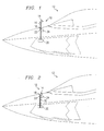
- an angle of sideslip measuring instrument 10 is incorporated into a low observable aircraft 12 to provide aircraft 12 with input regarding its angle of sideslip, known as ⁇ , through the air.
- a tetrahedron-shaped, aerodynamically stable probe 14 is coupled to a supporting shaft 16, which acts as a support member to extend probe 14 into the airflow of aircraft 12.
- a tetrahedron-shaped cavity 18 is formed in aircraft 12 to accept and stow tetrahedron probe 14.
- Shaft 16 extends through the surface of aircraft 12 and is rotationally coupled to a retraction-extension mechanism 20.
- Shaft 16 also extends through a slip collar 22 which is operationally coupled to a position sensor 24.
- Shaft 16 can be made of any acceptable material, including radar-absorbing material, and can be an aerodynamic shape to reduce drag, such as a circular shape, or can have sharp corners to reduce its radar signature.
- the position sensor 24 can be a variable resistance or rheostat potentiometer-type sensor which provides a direct analog output of the rotational position of probe 14.
- Shaft 16 is long enough to extend tetrahedron probe 14 between six and eight inches above the surface of aircraft 12. This allows tetrahedron probe 14 to act as a weathervane-type device by aligning with the relative wind without experiencing interference from the boundary layer of the airflow along aircraft 12. As tetrahedron probe 14 aligns with the relative wind, shaft 16 rotates causing slip collar 22 to also rotate. The amount of rotation of slip collar 22 is measured by a mechanical linkage between slip collar 22 and position sensor 24. Position sensor 24 then translates the rotational position of probe 14 into an electrical signal which can be transmitted to the flight control system of aircraft 12.
- Retraction-extension mechanism 20 can be any electrical, pneumatic, hydraulic or other system which can act as a motor to raise and lower support shaft 16. In one embodiment, retraction-extension mechanism 20 can be a simple gear drive similar to the systems used to raise and lower car radio antennas.
- tetrahedron probe 14 is stowed in cavity 18 as it could be during high speed flight. During retraction, tetrahedron probe 14 can be aligned with cavity 18 by mechanical means or can self-align as tetrahedron probe 14 conforms with like-shaped cavity 18.
- tetrahedron probe 14 is stowed in cavity 18 in a low observable configuration.
- Low observable aircraft 12 has a number of body parts which are constructed along predetermined radar reflection lines such as parallel lines 26 and 28.
- the planform edges of tetrahedron probe 14 correspond with parallel lines 26 and 28 so that the probe does not increase the radar signature of aircraft 12.
- tetrahedron-shaped probe 14 is coupled to supporting shaft 16 at pivot axis 30.
- Probe 14 and shaft 16 can be constructed of any suitable material, although materials with low radar reflectivity or radar absorbing qualities could help reduce the overall radar signature of aircraft 12.
- the location of pivot axis 30 ensures that tetrahedron probe 14 will act as an aerodynamically stable weathervane-type device.
- Pivot axis 30 should be located at a point between the front and the center of pressure of tetrahedron probe 14.
- the portion of tetrahedron probe 14 aft of pivot axis 30 has more side projected area than the portion of tetrahedron probe 14 located in front of pivot axis 30, which causes the front of probe 14 to point into the relative wind.
- probes having other shapes could be used, such as circular, rectangular or conical shapes.
- shaft 16 should be located in front of the center of pressure of the selected probe.
- retraction-extension mechanism 20 extends or retracts probe 14 into or out of the airflow of aircraft 12 along an axis that is parallel to the yaw axis of the aircraft.
- Angle of sideslip measuring instrument 10 can commence or cease providing angle of sideslip information upon receiving a manual command from the pilot or upon determining the existence of another predetermined condition. Any of a number of predetermined conditions can initiate the extension or retraction of probe 14, including a particular airspeed, a particular angle of attack, the position of the landing gear, the position of the landing gear handle, or any other condition that indicates the aircraft is entering a slow speed flight regime. Similarly, any of a number of operational predetermined conditions can initiate retraction or extension of probe 14.
- the retraction-extension mechanism 20 can retract probe 14 if the aircraft's radar warning receiver or other electromagnetic warfare device detects radar scanning by an enemy detection or weapon device.
- the aircraft's flight control computer can test for a set of predetermined conditions for extension and a set for retraction, and can direct retraction-extension mechanism 20 as appropriate.
- Aerodynamically stable probe 14 aligns with the relative wind across the aircraft when probe 14 is extended into the airstream, causing support shaft 16 to rotate.
- Position sensor 24 can measure the direction of the airflow across aircraft 12 by measuring the rotational position of support shaft 16 and comparing the measured direction with the direction of airflow normally experienced across aircraft 12, which allows a determination of angle of sideslip.
- any sensor capable of measuring the rotational position of probe 14 can be used.
- the sensor can be associated directly with probe 14, or can be indirectly associated through the translation of movement of probe 14 by support shaft 16.
- probe 14 can be rotationally coupled to supporting shaft 16, so that the probe can align with the relative wind, but supporting shaft 16 remains in a constant position.
- sensor 24 could actually be located within the body of probe 14. In other embodiments, position sensor 24 can be located at any convenient location, including within retraction-extension mechanism 20. Further, probe 14 can be aligned with an axis other than the yaw axis to also measure airflow in other directions, such as the angle of attack.
- probe 14 can be painted a bright color and placed in front of the cockpit to provide visual indications of angle of sideslip to the pilot. When the probe is located in the visual range of the pilot, it can also give the pilot a visual indication that the predetermined condition, such as the position of the gear or the amount of angle of attack, has been met.
- probe 14 can be relocated to any spot on aircraft 12 where the relative wind can be detected without interference from the boundary layer around aircraft 12. For instance, probe 14 could extend from the landing gear, extend from other portions on the bottom of the aircraft, extend from the wing, or extend from the tail as depicted in FIGURE 5. In these embodiments, the angle of sideslip detected by probe 14 would be automatically forwarded to a flight control system to manage the flight of aircraft 12 throughout the slow speed flight regime.
- retraction-extension mechanism 20 retracts probe 14 into the body of aircraft 12.
- the aircraft has a cavity 18, which is the same shape as the probe 14 and which accepts the probe as it is retracted into the aircraft.
- angle of sideslip is generally minimal, so the probe should naturally align with the cavity.
- the tetrahedron shape of probe 14 and the accompanying tetrahedron shape of cavity 18 assists the probe's alignment as it enters cavity 18.
- a mechanism can be included to align the probe during retraction.
- the probe can be completely stowed within the body of aircraft 12 by any convenient means so as to minimize radar reflections.
- the present invention provides a number of technical advantages, whether or not it is incorporated in a low observable aircraft. For instance, a retracted probe does not cause unnecessary drag. A retracted probe is not subject to the excessive aerodynamic forces which can be produced at high speeds, and thus does not have to be constructed to be as sturdy as a probe that always remains in the airflow of the aircraft. In addition to having a reduced radar signature, the tetrahedron shape of the probe allows self-alignment during retraction. Further, the probe provides accurate and simple measurements of angle of sideslip in the slow speed flight regime, as well as visual indications to the pilot of angle of sideslip.
Landscapes
- Physics & Mathematics (AREA)
- General Physics & Mathematics (AREA)
- Engineering & Computer Science (AREA)
- Aviation & Aerospace Engineering (AREA)
- Radar Systems Or Details Thereof (AREA)
Applications Claiming Priority (2)
| Application Number | Priority Date | Filing Date | Title |
|---|---|---|---|
| US08/864,652 US5852237A (en) | 1997-05-28 | 1997-05-28 | Apparatus and method for measuring the side slip of a low observable aircraft |
| US864652 | 2004-06-08 |
Publications (2)
| Publication Number | Publication Date |
|---|---|
| EP0881498A2 true EP0881498A2 (de) | 1998-12-02 |
| EP0881498A3 EP0881498A3 (de) | 1999-09-15 |
Family
ID=25343757
Family Applications (1)
| Application Number | Title | Priority Date | Filing Date |
|---|---|---|---|
| EP98250173A Withdrawn EP0881498A3 (de) | 1997-05-28 | 1998-05-22 | Vorrichtung und Methode zur Messung des Seitengleitwinkels von Stealth-Flugzeugen |
Country Status (2)
| Country | Link |
|---|---|
| US (1) | US5852237A (de) |
| EP (1) | EP0881498A3 (de) |
Cited By (2)
| Publication number | Priority date | Publication date | Assignee | Title |
|---|---|---|---|---|
| EP2937701A1 (de) * | 2014-04-25 | 2015-10-28 | The Boeing Company | Grenzschichtdurchflusssensor |
| WO2024230863A1 (de) * | 2023-05-08 | 2024-11-14 | Dr. Franke und Dr. Hitzler Entwicklungen UG (haftungsbeschränkt) + Co. KG | Sonde für ein luftfahrzeug, luft-datensystem mit einer sonde und luftfahrzeug mit einer sonde |
Families Citing this family (21)
| Publication number | Priority date | Publication date | Assignee | Title |
|---|---|---|---|---|
| US5753505A (en) * | 1995-07-06 | 1998-05-19 | Emory University | Neuronal progenitor cells and uses thereof |
| US6209994B1 (en) | 1997-09-17 | 2001-04-03 | Seiko Epson Corporation | Micro device, ink-jet printing head, method of manufacturing them and ink-jet recording device |
| WO1999032963A1 (en) * | 1997-12-22 | 1999-07-01 | Accurate Automation Corporation | Air data sensor apparatus and method |
| FR2817044B1 (fr) * | 2000-11-17 | 2003-02-14 | Thomson Csf | Procede de determination de parametres aerodynamiques et procede de detection de panne d'une sonde utilisee pour determiner les parametres aerodynamiques |
| US6609421B2 (en) * | 2001-05-08 | 2003-08-26 | Rosemount Aerospace Inc. | Sideslip correction for a multi-function three probe air data system |
| US6561020B2 (en) * | 2001-05-08 | 2003-05-13 | Rosemount Aerospace Inc. | Method to calculate sideslip angle and correct static pressure for sideslip effects using inertial information |
| USD488728S1 (en) | 2003-04-17 | 2004-04-20 | Robert Wayne Brantl | Stealth weathervane |
| CA107187S (en) | 2004-06-02 | 2005-09-01 | Bob Damberger | Wind direction indicator |
| USH2206H1 (en) * | 2004-10-28 | 2007-12-04 | The United States Of America As Represented By The Secretary Of The Navy | Tactile side-slip corrective yaw control for aircraft |
| US7377159B2 (en) * | 2005-08-16 | 2008-05-27 | Honeywell International Inc. | Methods and system for determining angles of attack and sideslip using flow sensors |
| US8733707B2 (en) * | 2008-04-17 | 2014-05-27 | The Boeing Company | Line transfer system for airplane |
| US8326587B2 (en) * | 2007-12-13 | 2012-12-04 | The Boeing Company | System, method, and computer program product for predicting cruise orientation of an as-built airplane |
| US8005563B2 (en) | 2007-10-26 | 2011-08-23 | The Boeing Company | System for assembling aircraft |
| US7966872B2 (en) * | 2008-07-23 | 2011-06-28 | The Boeing Company | In-flight testing kits and methods for evaluating proposed aerodynamic structures for aircraft |
| FR2942871B1 (fr) * | 2009-03-06 | 2011-04-01 | Institut Franco Allemand De Rech De Saint Louis | Dispositif de pilotage d'un missile ou d'un projectile |
| US8352099B1 (en) * | 2009-07-09 | 2013-01-08 | The Boeing Company | Varying engine thrust for directional control of an aircraft experiencing engine thrust asymmetry |
| CN102175193A (zh) * | 2010-12-30 | 2011-09-07 | 清华大学 | 叶片式直升机侧滑角传感器 |
| CN105571613A (zh) * | 2015-12-11 | 2016-05-11 | 北京青云航空仪表有限公司 | 一种侧滑仪灵敏度通用检测平台 |
| CN111846192B (zh) * | 2020-06-04 | 2022-06-17 | 中国人民解放军国防科技大学 | 一种飞行器参数在线辨识飞行验证模拟舱段 |
| CN115629547B (zh) * | 2022-12-08 | 2023-04-25 | 西北工业大学 | 一种面向舵面故障的飞机机载容错控制方法及系统 |
| CN120779055A (zh) * | 2025-07-03 | 2025-10-14 | 中国商用飞机有限责任公司 | 用于飞机蒙皮的表面边界层速度分布的测量装置 |
Family Cites Families (14)
| Publication number | Priority date | Publication date | Assignee | Title |
|---|---|---|---|---|
| US3079105A (en) * | 1957-10-21 | 1963-02-26 | Raspet Mabel Wilson | Reserve lift indicator for aircraft and the like |
| FR2231564B1 (de) * | 1973-05-29 | 1976-11-12 | Dassault Avions | |
| US4230290A (en) * | 1978-05-01 | 1980-10-28 | Townsend Engineering Company | Airplane angle of attack and direction of flight indicator |
| US5250950A (en) * | 1979-02-13 | 1993-10-05 | Lockheed Corporation | Vehicle |
| US4212199A (en) * | 1979-02-28 | 1980-07-15 | The United States Of America As Represented By The Administrator Of The National Aeronautics And Space Administration | System for use in conducting wake investigation for a wing in flight |
| US4567760A (en) * | 1984-01-18 | 1986-02-04 | Crowder James P | Flow direction and state indicator |
| US4814764A (en) * | 1986-09-30 | 1989-03-21 | The Boeing Company | Apparatus and method for warning of a high yaw condition in an aircraft |
| GB2231667B (en) * | 1989-05-08 | 1992-11-18 | Rosemount Ltd | Deployable probe |
| US5115237A (en) * | 1990-04-16 | 1992-05-19 | Safe Flight Instrument Corporation | Combination aircraft yaw/angle of attack sensor |
| US5209430A (en) * | 1991-11-07 | 1993-05-11 | The United States Of America As Represented By The Administrator Of The National Aeronautics And Space Administration | Helicopter low-speed yaw control |
| US5442958A (en) * | 1992-12-15 | 1995-08-22 | The B.F. Goodrich Company | Deployable probe combined with flush static port |
| US5323649A (en) * | 1993-01-19 | 1994-06-28 | Carlson Carl H | Airport wind direction and velocity indicator |
| US5438865A (en) * | 1993-12-16 | 1995-08-08 | Safe Flight Instrument Corporation | Angle of attack sensor |
| US5564652A (en) * | 1995-01-03 | 1996-10-15 | The Boeing Compay | Body spoiler for yaw control of a supersonic airplane |
-
1997
- 1997-05-28 US US08/864,652 patent/US5852237A/en not_active Expired - Fee Related
-
1998
- 1998-05-22 EP EP98250173A patent/EP0881498A3/de not_active Withdrawn
Cited By (4)
| Publication number | Priority date | Publication date | Assignee | Title |
|---|---|---|---|---|
| EP2937701A1 (de) * | 2014-04-25 | 2015-10-28 | The Boeing Company | Grenzschichtdurchflusssensor |
| US9592920B2 (en) | 2014-04-25 | 2017-03-14 | The Boeing Company | Boundary layer flow sensor |
| US9933330B2 (en) | 2014-04-25 | 2018-04-03 | The Boeing Company | Boundary layer flow sensor |
| WO2024230863A1 (de) * | 2023-05-08 | 2024-11-14 | Dr. Franke und Dr. Hitzler Entwicklungen UG (haftungsbeschränkt) + Co. KG | Sonde für ein luftfahrzeug, luft-datensystem mit einer sonde und luftfahrzeug mit einer sonde |
Also Published As
| Publication number | Publication date |
|---|---|
| EP0881498A3 (de) | 1999-09-15 |
| US5852237A (en) | 1998-12-22 |
Similar Documents
| Publication | Publication Date | Title |
|---|---|---|
| US5852237A (en) | Apparatus and method for measuring the side slip of a low observable aircraft | |
| US6547181B1 (en) | Ground effect wing having a variable sweep winglet | |
| EP3201711B1 (de) | Flugzeug und verfahren zur ausrichtung eines flugwerks eines flugzeugs | |
| AU2014307569B2 (en) | Convertiplane with new aerodynamic and technical solutions which make the aircraft safe and usable | |
| EP0502811B1 (de) | Hubschraubergewichtsmessung | |
| GB1584721A (en) | Airport wind conditions monitoring method and apparatus | |
| GB2077202A (en) | An apparatus for refueling an aircraft from a ship at sea | |
| US4559822A (en) | Aircraft potential of wing lift instrument and method | |
| GB2176073A (en) | Bird avoidance system | |
| US11577830B2 (en) | Aircraft | |
| Innis et al. | Flight tests under IFR with an STOL transport aircraft | |
| Patterson Jr et al. | Ground development and flight correlation of the vortex attenuating spline device | |
| Beeler et al. | Measurements of the Wing and Tail Loads during the Acceptance Tests of Bell XS-1 Research Airplane | |
| Gallant et al. | Flight tests under IFR with an STOL transport aircraft | |
| Yamakawa et al. | Attack Helicopter Evaluation, Blackhawk S-67 Helicopter | |
| Fearnside | Instrument aids for take-off | |
| Stillwell et al. | Flight Measurements with the Douglas D-558-II (BuAero No. 37974) Research Airplane | |
| Friend et al. | Flight comparison of the transonic agility of the F-111A airplane and the F-111 supercritical wing airplane | |
| Johnson et al. | Engineering Evaluation, AH-56A Compound Helicopter with Advanced Mechanical Control System | |
| Kimberlin | Performance flight testing of a single engine powered lift aircraft | |
| Eldredge et al. | Flight-determined low-speed lift and drag characteristics of the lightweight m2-f1 lift-ing body | |
| Fowler | Determination of Breguet 941 STOL Aircraft Transition Velocities with Various Flap Deflections | |
| Hammond et al. | Variable sweep aircraft Patent | |
| Acree | An upgrade to the A-10A airplane | |
| Sjoberg et al. | Flight Measurements with the Douglas D-558-II (buaero No. 37974) Research Airplane: Static Longitudinal Stability and Control Characteristics at Mach Numbers up to 0.87 |
Legal Events
| Date | Code | Title | Description |
|---|---|---|---|
| PUAI | Public reference made under article 153(3) epc to a published international application that has entered the european phase |
Free format text: ORIGINAL CODE: 0009012 |
|
| AK | Designated contracting states |
Kind code of ref document: A2 Designated state(s): DE FR GB IT SE |
|
| AX | Request for extension of the european patent |
Free format text: AL;LT;LV;MK;RO;SI |
|
| PUAL | Search report despatched |
Free format text: ORIGINAL CODE: 0009013 |
|
| AK | Designated contracting states |
Kind code of ref document: A3 Designated state(s): AT BE CH CY DE DK ES FI FR GB GR IE IT LI LU MC NL PT SE |
|
| AX | Request for extension of the european patent |
Free format text: AL;LT;LV;MK;RO;SI |
|
| AKX | Designation fees paid | ||
| REG | Reference to a national code |
Ref country code: DE Ref legal event code: 8566 |
|
| 17P | Request for examination filed |
Effective date: 20000314 |
|
| RBV | Designated contracting states (corrected) |
Designated state(s): DE FR GB IT SE |
|
| 17Q | First examination report despatched |
Effective date: 20011025 |
|
| RAP1 | Party data changed (applicant data changed or rights of an application transferred) |
Owner name: LOCKHEED MARTIN CORPORATION |
|
| GRAP | Despatch of communication of intention to grant a patent |
Free format text: ORIGINAL CODE: EPIDOSNIGR1 |
|
| STAA | Information on the status of an ep patent application or granted ep patent |
Free format text: STATUS: THE APPLICATION IS DEEMED TO BE WITHDRAWN |
|
| 18D | Application deemed to be withdrawn |
Effective date: 20041201 |