EP2937667A2 - Angilar velocity sensor, electronic apparatus, and mobile object - Google Patents
Angilar velocity sensor, electronic apparatus, and mobile object Download PDFInfo
- Publication number
- EP2937667A2 EP2937667A2 EP15164203.0A EP15164203A EP2937667A2 EP 2937667 A2 EP2937667 A2 EP 2937667A2 EP 15164203 A EP15164203 A EP 15164203A EP 2937667 A2 EP2937667 A2 EP 2937667A2
- Authority
- EP
- European Patent Office
- Prior art keywords
- unit
- mass
- units
- angular velocity
- velocity sensor
- Prior art date
- Legal status (The legal status is an assumption and is not a legal conclusion. Google has not performed a legal analysis and makes no representation as to the accuracy of the status listed.)
- Granted
Links
- 230000008878 coupling Effects 0.000 claims abstract description 82
- 238000010168 coupling process Methods 0.000 claims abstract description 82
- 238000005859 coupling reaction Methods 0.000 claims abstract description 82
- 239000000758 substrate Substances 0.000 claims abstract description 46
- 238000001514 detection method Methods 0.000 claims description 107
- 238000006073 displacement reaction Methods 0.000 claims description 52
- 238000012544 monitoring process Methods 0.000 claims description 18
- 230000009467 reduction Effects 0.000 claims description 8
- 244000126211 Hericium coralloides Species 0.000 claims description 5
- 238000010586 diagram Methods 0.000 description 37
- 230000008859 change Effects 0.000 description 14
- 230000006870 function Effects 0.000 description 10
- 239000000463 material Substances 0.000 description 8
- 230000004048 modification Effects 0.000 description 8
- 238000012986 modification Methods 0.000 description 8
- 239000004065 semiconductor Substances 0.000 description 8
- 230000000694 effects Effects 0.000 description 6
- 238000003384 imaging method Methods 0.000 description 6
- 230000035945 sensitivity Effects 0.000 description 5
- 230000003287 optical effect Effects 0.000 description 4
- 238000004891 communication Methods 0.000 description 3
- 239000011521 glass Substances 0.000 description 3
- 238000000034 method Methods 0.000 description 3
- 229910052710 silicon Inorganic materials 0.000 description 3
- 239000010703 silicon Substances 0.000 description 3
- 238000010521 absorption reaction Methods 0.000 description 2
- 229910001413 alkali metal ion Inorganic materials 0.000 description 2
- 230000003321 amplification Effects 0.000 description 2
- 238000003199 nucleic acid amplification method Methods 0.000 description 2
- RZVAJINKPMORJF-UHFFFAOYSA-N Acetaminophen Chemical compound CC(=O)NC1=CC=C(O)C=C1 RZVAJINKPMORJF-UHFFFAOYSA-N 0.000 description 1
- 241000251468 Actinopterygii Species 0.000 description 1
- WQZGKKKJIJFFOK-GASJEMHNSA-N Glucose Natural products OC[C@H]1OC(O)[C@H](O)[C@@H](O)[C@@H]1O WQZGKKKJIJFFOK-GASJEMHNSA-N 0.000 description 1
- 230000008901 benefit Effects 0.000 description 1
- 239000008280 blood Substances 0.000 description 1
- 210000004369 blood Anatomy 0.000 description 1
- 230000036772 blood pressure Effects 0.000 description 1
- 239000005388 borosilicate glass Substances 0.000 description 1
- 238000006243 chemical reaction Methods 0.000 description 1
- 238000011549 displacement method Methods 0.000 description 1
- 238000005530 etching Methods 0.000 description 1
- -1 for example Substances 0.000 description 1
- 239000008103 glucose Substances 0.000 description 1
- 239000011810 insulating material Substances 0.000 description 1
- 238000009413 insulation Methods 0.000 description 1
- 150000002500 ions Chemical class 0.000 description 1
- 230000007257 malfunction Effects 0.000 description 1
- 239000005297 pyrex Substances 0.000 description 1
- 230000003252 repetitive effect Effects 0.000 description 1
- GGCZERPQGJTIQP-UHFFFAOYSA-N sodium;9,10-dioxoanthracene-2-sulfonic acid Chemical compound [Na+].C1=CC=C2C(=O)C3=CC(S(=O)(=O)O)=CC=C3C(=O)C2=C1 GGCZERPQGJTIQP-UHFFFAOYSA-N 0.000 description 1
Images






Classifications
-
- G—PHYSICS
- G01—MEASURING; TESTING
- G01C—MEASURING DISTANCES, LEVELS OR BEARINGS; SURVEYING; NAVIGATION; GYROSCOPIC INSTRUMENTS; PHOTOGRAMMETRY OR VIDEOGRAMMETRY
- G01C19/00—Gyroscopes; Turn-sensitive devices using vibrating masses; Turn-sensitive devices without moving masses; Measuring angular rate using gyroscopic effects
- G01C19/56—Turn-sensitive devices using vibrating masses, e.g. vibratory angular rate sensors based on Coriolis forces
- G01C19/5719—Turn-sensitive devices using vibrating masses, e.g. vibratory angular rate sensors based on Coriolis forces using planar vibrating masses driven in a translation vibration along an axis
- G01C19/5733—Structural details or topology
- G01C19/574—Structural details or topology the devices having two sensing masses in anti-phase motion
-
- G—PHYSICS
- G01—MEASURING; TESTING
- G01C—MEASURING DISTANCES, LEVELS OR BEARINGS; SURVEYING; NAVIGATION; GYROSCOPIC INSTRUMENTS; PHOTOGRAMMETRY OR VIDEOGRAMMETRY
- G01C19/00—Gyroscopes; Turn-sensitive devices using vibrating masses; Turn-sensitive devices without moving masses; Measuring angular rate using gyroscopic effects
- G01C19/56—Turn-sensitive devices using vibrating masses, e.g. vibratory angular rate sensors based on Coriolis forces
- G01C19/5719—Turn-sensitive devices using vibrating masses, e.g. vibratory angular rate sensors based on Coriolis forces using planar vibrating masses driven in a translation vibration along an axis
Definitions
- the present invention relates to an angular velocity sensor, an electronic apparatus and a mobile object which include the angular velocity sensor.
- a gyroscope (hereinafter, referred to as an angular velocity sensor) with a configuration in which a plurality of drive masses (hereinafter, referred to as mass units) disposed on a substrate as an angular velocity sensor corresponding to angular velocities of three detection axis rotations are coupled to each other by elastic coupling elements (hereinafter, referred to as coupling units), at least one mass unit is subjected to drive movement (hereinafter, referred to as drive vibration) by a drive unit, and thereby the drive vibration is transferred to another mass unit through the coupling unit, further, in a state in which a plurality of mass units is subjected to the drive vibration, angular velocity which is applied thereto is detected using detection vibration of detection units which are provided in a plurality of mass units, is known (for example, refer to European Patent Application Publication No. 2339293 ).
- the angular velocity sensor has a configuration in which two mass units (hereinafter, referred to as first mass pair) are subjected to drive vibration directly by a drive unit, thereby the drive vibration is transferred with a given rate to the other two mass units (hereinafter, referred to as second mass pair) through a coupling unit, and a total of four mass units is subjected to the drive vibration.
- the given rate may not be approximately 1:1 due to consumption of drive vibration energy or the like caused by, for example, a coupling unit having elasticity.
- an amplitude of the drive vibration of the second mass pair to which the drive vibration is transferred from the first mass pair through the coupling unit may be smaller than an amplitude of the first mass pair which is subjected to drive vibration directly by a drive unit.
- an amplitude of detection vibration of a detection unit of the second mass pair at the time of applying angular velocity may be smaller than an amplitude of a detection unit of the first mass pair, and thus there may be a difference between detection sensitivities of detection axis rotation of each of three detection axis rotation angular velocities which are detected by detection units of the four mass units.
- an angular velocity sensor including a substrate; a plurality of mass units which is disposed on the substrate; coupling units which couple the mass units that are adjacent to each other, among the plurality of mass units; and drive units which are disposed on the substrate and are connected to the coupling units, in which the drive units respectively drive the mass units that are adjacent to each other through the coupling units.
- the angular velocity sensor includes the coupling units which couple the mass units that are adjacent to each other, and the moving units which are connected to the coupling units. Also, the drive units respectively drive the mass units that are adjacent to each other through the coupling units.
- the angular velocity sensor can substantially equally drive the mass units that are adjacent to each other, and thus it is possible to make an amount of displacement (for example, amplitude of drive vibration) of the mass units at the time of driving substantially equal to each other.
- the angular velocity sensor can make an amount of displacement (for example, amplitude of detection vibration) of the mass units at the time of detecting angular velocity substantially equal to each other, and thus it is possible to reduce a difference of detection sensitivity of angular velocity between the respective detection axes.
- the drive units drive the respective mass units such that the second mass pair is displaced in a direction that separates the pair from each other, when the first mass pair is displaced in a direction that brings the pair toward each other, and such that the second mass pair is displaced in a direction that brings the pair toward each other, when the first mass pair is displaced in a direction that separates the pair from each other.
- the drive units of the angular velocity sensor drive the respective mass units such that the second mass pair is displaced in a direction that separates the pair from each other, when the first mass pair is displaced in a direction that brings the pair toward each other, and such that the second mass pair is displaced in a direction that brings the pair toward each other, when the first mass pair is displaced in a direction that separates the pair from each other.
- the displacement method in other words, vibration mode of drive vibration
- the angular velocity sensor can suppress generation of an unnecessary vibration mode at the time of driving.
- the angular velocity sensor can omit or simplify a frequency control used for limiting the unnecessary vibration mode.
- At least the one of mass units of the first mass pair includes a first detection unit which detects angular velocity of a second axis rotation
- at least the one of mass units of the second mass pair includes a second detection unit which detects angular velocity of a first axis rotation
- at least one mass unit of at least the one of the first mass pair and the second mass pair includes a third detection unit which detects angular velocity of a third axis rotation which intersects a flat plane along the first axis and the second axis.
- the angular velocity sensor can reduce a difference in detection sensitivity between the respective detection axes (first axis to third axis) using the respective detection units and can detect the angular velocity of three detection axis rotations.
- Application Example 4
- At least one of the plurality of mass units includes a monitoring unit which monitors displacement of the mass unit at the time of driving.
- the angular velocity sensor can maintain an amount of displacement at the time of driving the respective mass units at a predetermined level, for example, by electromechanically converting the displacement, amplifying the displacement, and applying the displacement to the drive unit.
- the coupling unit is formed in an arc shape having the center thereof between the mass units that are adjacent to each other
- the drive unit includes a fixing unit that includes the center of the arc shape and is fixed to the substrate and a moving unit which connects the fixing unit to the coupling unit, and the moving unit and the coupling unit can rotate using the fixing unit as the center thereof.
- the coupling unit of the angular velocity sensor is formed in an arc shape
- the angular velocity sensor includes a drive unit including a fixing unit which is fixed on the substrate, and a moving unit which connects the fixing unit to the coupling unit, and the moving unit and the coupling unit can rotate using the fixing unit as the center thereof.
- the drive unit can smoothly drive the respective mass units through the coupling unit.
- the fixing electrode and the moving electrode of the drive units include electrode fingers of a comb shape meshing with each other, the electrode fingers are formed in an arc shape using the fixing unit as the center thereof, and thus the angular velocity sensor can smoothly rotate the moving unit and the coupling unit using the fixing unit as the center thereof.
- Application Example 7
- the coupling unit includes a stress reduction unit in a connection unit between the coupling unit and the mass unit.
- the coupling unit includes a stress reduction unit in a connection unit between the coupling unit and the mass unit, and thus, the angular velocity sensor can reduce concentration of the stress occurring in the connection unit between the coupling unit and the mass unit at the time of driving.
- an electronic apparatus including the angular velocity sensor which is described in any one of the application examples.
- an electronic apparatus of the present configuration includes the angular velocity sensor which is described in any one of the above-described application examples, and thus an electronic apparatus which obtains the effects that are described in any one of the above-described application examples can be provided.
- a mobile object including the angular velocity sensor which is described in any one of the application examples.
- a mobile object of the present configuration includes the angular velocity sensor which is described in any one of the above-described application examples, and thus a mobile object which obtains the effects that are described in any one of the above-described application examples can be provided.
- Fig. 1 is a schematic plan diagram illustrating a schematic configuration of an angular velocity sensor according to a first embodiment.
- Figs. 2 to 4B are enlarged schematic diagrams of essential units of Fig. 1
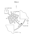
- Fig. 2 is an enlarged schematic plan diagram of one essential portion of Fig. 1
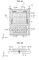
- Fig. 3A is an enlarged schematic plan diagram of another essential portion of Fig. 1
- Fig. 3B is a schematic cross-sectional diagram cut along line IIIB-IIIB of Fig. 3A
- Fig. 4A is an enlarged schematic plan diagram of still another essential portion of Fig. 1
- Fig. 4B is a schematic cross-sectional diagram cut along line IVB-IVB of Fig. 4A .
- an X axis, a Y axis, and a Z axis are coordinate axes which are orthogonal to each other, and the direction of an arrow is a + (plus) direction.
- an angular velocity sensor 1 includes a substrate 10 of an approximately flat plate shape, a first mass unit 21, a second mass unit 22, a third mass unit 23, and a fourth mass unit 24 which are a plurality (here, four) of mass units that are disposed on the substrate 10, coupling units 31 to 34 which respectively couple the first mass unit 21 and the third mass unit 23, the third mass unit 23 and the second mass unit 22, the second mass unit 22 and the fourth mass unit 24, and the fourth mass unit 24 and the first mass unit 21 which are adjacent to each other, among the plurality of mass units, and drive units 41 to 44 which are disposed on the substrate 10 and are connected to the coupling units 31 to 34.
- the plurality of mass units includes a first mass pair A in which the first mass unit 21 and the second mass unit 22 which are two mass units are disposed in a facing manner along the X axis which is defined as a first axis, and a second mass pair B in which the third mass unit 23 and the fourth mass unit 24, which are another two mass units, are disposed in a facing manner along the Y axis which is defined as a second axis which intersects (here, orthogonal) the X axis in a planar view.
- the respective mass units 21 to 24 are formed in an approximately rectangular shape, and end portions opposite to end portions which are connected to the respective coupling units 31 to 34 are connected to the fixing units 51 which protrude from the substrate 10 through a spring unit 50.
- the spring units 50 are provided as a pair in the end portions of the respective mass units 21 to 24.
- the spring units protrude in the Y-axis direction and extend in the X-axis direction thereby being connected to the fixing units 51
- the spring units protrude in the X-axis direction and extend in the Y-axis direction thereby being connected to the fixing units 51.
- the first mass pair A can be displaced in the X-axis direction by deflection (deformation) of the spring unit 50, and the second mass pair B can be displaced in the Y-axis direction in the same manner.
- a predetermined gap is provided between the respective mass units 21 to 24 and the substrate 10, in order to avoid interference at the time of displacement(for example, a concave portion which is not illustrated in the substrate 10 is provided).
- the coupling units 31 to 34 are formed in arc shapes which respectively have centers O1 to 04, between the first mass unit 21 and the third mass unit 23, between the third mass unit 23 and the second mass unit 22, between the second mass unit 22 and the fourth mass unit 24, and between the fourth mass unit 24 and the first mass unit 21, which are mass units that are adjacent to each other.
- the respective drive units 41 to 44 include a fixing unit 45 which includes the respective centers O1 to 04 of the arcs and are fixed to the substrate 10, and a moving unit 46 which connects the fixing unit 45 to the respective coupling units 31 to 34.
- the respective drive units 41 to 44 are configured to be able to rotate the moving unit 46 and the respective coupling units 31 to 34 using the fixing unit 45 as the center thereof.
- the respective drive units 41 to 44 include a pair of fixing electrodes 47 which are provided on the substrate 10 so as to interpose the moving unit 46 between the fixing electrodes 47, and a moving electrode 48 which is provided in the moving unit 46.
- the fixing electrode 47 and the moving electrode 48 include comb-shaped electrode fingers 47a and 48a meshing with each other, and the electrode fingers 47a and 48a are respectively formed in an arc shape using the fixing unit 45 as the center thereof.
- the fixing electrode 47 and the moving electrode 48 are spread in a fan shape using the fixing unit 45 as the center thereof.
- the respective drive units 41 to 44 apply a voltage between the fixing electrode 47 and the moving electrode 48 using, for example, a drive circuit which is not illustrated, and can alternately rotate the moving unit 46 and the respective coupling units 31 to 34 using electrostatic drive caused by electrostatic force (electrostatic attractive force, electrostatic repulsive force) between the fixing electrode 47 and the moving electrode 48, in a clockwise direction (white arrow direction) and a counter-clockwise direction (black arrow direction) using the fixing unit 45 as the center thereof.
- electrostatic force electrostatic attractive force, electrostatic repulsive force
- first mass unit 21 and the second mass unit 22 are symmetrically shaped with respect to a straight line along the Y axis which passes between the first mass unit 21 and the second mass unit 22, and the third mass unit 23 and the fourth mass unit 24 are symmetrically shaped with respect to a straight line along the X axis which passes between the third mass unit 23 and the fourth mass unit 24.
- the first mass unit 21 and the second mass unit 22 which are at least one (here, two) mass unit of the first mass pair A include first detection units 61a and 61b that detect Y-axis rotation angular velocity
- the third mass unit 23 and the fourth mass unit 24 which are at least one (here, two) mass unit of the second mass pair B include second detection units 62a and 62b that detect X-axis rotation angular velocity.
- first mass unit 21 and the second mass unit 22 which are at least one (here, two) mass unit of at least one (here, the first mass pair A) of the first mass pair A and the second mass pair B include third detection units 63a and 63b which detect angular velocity of Z-axis rotation defined as a third axis which intersects (here, orthogonal) a plane along the X axis and the Y axis.
- At least one (here, two units which are the third mass unit 23 and the fourth mass unit 24) of the mass units 21 to 24 includes monitoring units 64a and 64b which monitor displacement of the third mass unit 23 and the fourth mass unit 24 at the time of driving.
- the first mass unit 21 and the second mass unit 22 of the first mass pair A include frame units 21a and 22a (parentheses in Figs. 3A and 3B represent symbols of the second mass unit 22) of a rectangular frame shape, the first detection units 61a and 61b of a rectangular flat plate shape which are disposed inside the frame units 21a and 22a and detect the Y-axis rotation angular velocity, and the third detection units 63a and 63b of a rectangular lattice shape which are disposed inside the frame units 21a and 22a in parallel to the first detection units 61a and 61b in the X-axis direction and detect Z axis rotation angular velocity.
- the first detection units 61a and 61b are connected to the frame units 21a and 22a through a plurality (here, four) of spring units 52.
- the fixing electrode 11 which is larger than the first detection units 61a and 61b serving as moving electrodes by one rotation is provided on a surface, which is opposite to the first detection units 61a and 61b, on the substrate 10.
- two of the spring units 52 are respectively positioned in an end portion on a +Y side and in an end portion on a - (negative) Y side of the first detection units 61a and 61b, and are formed in a crank shape which extends in the Y-axis direction and is bent in the X-axis direction.
- the other two are positioned in an end portion which extends along the Y axis of the first detection units 61a and 61b, and are formed in a crank shape which extends in the X-axis direction and is bent in the Y-axis direction.
- the first detection units 61a and 61b detect a change occurring between the fixing electrode 11 and the first detection units 61a and 61b, for example, a change of capacitance, according to displacement in the Z-axis direction of the first detection units 61a and 61b serving as moving electrodes, and therefore are able to detect the Y-axis rotation angular velocity.
- the third detection units 63a and 63b are connected to the frame units 21a and 22a through a plurality (here, four) of spring units 53.
- fixing electrodes 63c and 63d which extend along the X axis are provided so as to interpose beam-shaped portions of the third detection units 63a and 63b serving as moving electrodes.
- the spring units 53 extend in the Y-axis direction while protruding in the X-axis direction, and connect an end portion on a +Y side and an end portion of -Y side of the third detection units 63a and 63b to the frame units 21a and 22a.
- the third detection units 63a and 63b detect a change occurring between the fixing electrodes 63c and 63d and the third detection units 63a and 63b, for example, a change of capacitance, according to displacement in the Y-axis direction of the third detection units 63a and 63b serving as moving electrodes, and therefore are able to detect the Z-axis rotation angular velocity.
- the third mass unit 23 and the fourth mass unit 24 of the second mass pair B include frame units 23a and 24a (parentheses in Figs. 4A and 4B represent symbols of the fourth mass unit 24) of a rectangular frame shape, the second detection units 62a and 62b of a rectangular flat plate shape which are disposed inside the frame units 23a and 24a and detect the X-axis rotation angular velocity, and monitoring units 64a and 64b which are disposed inside the frame units 23a and 24a in parallel with the second detection units 62a and 62b in the Y-axis direction and monitor displacement of the third mass unit 23 and the fourth mass unit 24 at the time of driving.
- frame units 23a and 24a parentheses in Figs. 4A and 4B represent symbols of the fourth mass unit 24
- the second detection units 62a and 62b of a rectangular flat plate shape which are disposed inside the frame units 23a and 24a and detect the X-axis rotation angular velocity
- monitoring units 64a and 64b which are disposed inside
- the second detection units 62a and 62b are connected to the frame units 23a and 24a through a plurality (here, four) of spring units 54.
- the fixing electrode 12 which is larger than the second detection units 62a and 62b serving as moving electrodes by one rotation is provided on a surface, which is opposite to the second detection units 62a and 62b, on the substrate 10.
- the spring units 54 are formed in a crank shape which is the same as the spring units 52, and connect an end portion extending along the X axis of the second detection units 62a and 62b, an end portion on a -X side, and an end portion on a +X side to the frame units 23a and 24a.
- the second detection units 62a and 62b detect a change occurring between the fixing electrode 12 and the second detection units 62a and 62b, for example, a change of capacitance, according to displacement in the Z-axis direction of the second detection units 62a and 62b serving as moving electrodes, and therefore are able to detect the X-axis rotation angular velocity.
- the monitoring units 64a and 64b extend in a beam shape along the X axis, are connected to the frame units 23a and 24a, and serve as moving electrodes.
- the fixing electrodes 64c and 64d which extend along the X axis are provided on the substrate 10, so as to interpose the beam shape portion of the monitoring units 64a and 64b.
- the monitoring units 64a and 64b and the fixing electrodes 64c and 64d are formed in a comb shape in such a manner that electrode fingers extending along the Y axis with a predetermined interval mesh with each other.
- the monitoring units 64a and 64b can monitor by mechanically and electrically converting (replacing) displacement of the beam shape portion in the Y-axis direction into a change between the fixing electrodes 64c and 64d and the monitoring units 64a and 64b, for example, a change of capacitance.
- an insulating material such as glass or high-resistivity silicon
- an insulating material such as glass or high-resistivity silicon
- an element plate that overlaps the substrate 10 and is attached to the respective mass units 21 to 24, the respective coupling units 31 to 34, the respective drive units 41 to 44, the spring unit 50, the fixing unit 51, or the like using etching or the like is a semiconductor element plate that is configured to use a semiconductor material such as silicon as a main material
- glass borosilicate glass, for example, Pyrex (registered trademark)
- alkali metal ions moving ion
- the angular velocity sensor 1 can anodically bond the substrate 10 to the semiconductor element plate.
- the angular velocity sensor 1 uses glass containing alkali metal ions for the substrate 10, and therefore the substrate 10 and the semiconductor element plate can be easily separated in an insulating manner.
- the substrate 10 may not have insulation properties, and for example, may be a conductive substrate which is configured of a low-resistivity silicon. In this case, an insulating film is interposed between the substrate 10 and the semiconductor element plate, and thereby both are separated in an insulating manner.
- thermal expansion coefficient difference between the configuration material of the substrate 10 and the configuration material of the semiconductor element plate is as small as possible. Specifically, it is preferable that the thermal expansion coefficient difference between the configuration material of the substrate 10 and the configuration material of the semiconductor element plate is equal to or less than 3 ppm/°C. By doing this, the angular velocity sensor 1 can reduce residual stress between the substrate 10 and the semiconductor element plate.
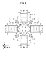
- Fig. 5 is a schematic plan diagram illustrating a drive vibration state of the angular velocity sensor
- Fig. 6A and Fig. 6B are schematic diagrams illustrating a force-adding method of the drive vibration state of the angular velocity sensor
- Fig. 7 is a block diagram illustrating a function of the monitoring unit which monitors the drive vibration state of the angular velocity sensor.
- Fig. 8 is a schematic plan diagram illustrating a detection vibration state of detecting the X-axis rotation angular velocity of the angular velocity sensor
- Fig. 9 is a schematic plan diagram illustrating a detection vibration state of detecting the Y-axis rotation angular velocity of the angular velocity sensor
- Fig. 10 is a schematic plan diagram illustrating a detection vibration state of detecting the Z-axis rotation angular velocity of the angular velocity sensor.
- the respective drive units 41 to 44 alternately rotate the respective coupling units 31 to 34 in a black arrow direction and a white arrow direction, such that the second mass pair B (the third mass unit 23 and the fourth mass unit 24) is displaced in a direction that separates the pair from each other (black arrow), when the first mass pair A (the first mass unit 21 and the second mass unit 22) is displaced in a direction that brings the pair toward each other, and such that the second mass pair B is displaced in a direction that brings the pair toward each other (white arrow), when the first mass pair A is displaced in a direction that separates the pair from each other.
- the respective mass units 21 to 24 are driven (drive vibration is performed).
- a component force F1y which is a component force along the Y axis of the force F1 and a component force F2y which is a component force along the Y axis of the force F2 are equal in magnitude and are opposite directionally, thereby cancelling one another.
- a component force F2x which is a component force along the X axis of the force F2 are equal in magnitude and are applied in the same direction, and therefore are added to each other along the X axis.
- the first mass unit 21 is displaced in the white arrow direction along the X axis.
- a component force F1'y which is a component force along the Y axis of the force F1', and a component force F2'y which is a component force along the Y axis of the force F2' are equal in magnitude and are opposite in direction, and therefore cancel one another.
- a component force F1'x which is a component force along the X axis of the force F1', and a component force F2'x which is a component force along the X axis of the force F2' are equal in magnitude and are also applied in the same direction, and therefore are added to each other along the X axis.
- the first mass unit 21 is displaced in the black arrow direction along the X axis.
- the respective mass units 21 to 24 are subjected to alternate and repetitive drive vibration of the displacement in the white arrow direction and the displacement in the black arrow direction.
- the monitoring units 64a and 64b which are illustrated in detail in Fig. 4A monitor displacement in the Y-axis direction of the third mass unit 23 and the fourth mass unit 24 as a change of capacitance between the fixing electrodes 64c and 64d and the monitoring units 64a and 64b.
- the angular velocity sensor 1 amplifies the change of capacitance which is monitored by the monitoring units 64a and 64b, in an amplification circuit 70 which uses, for example, an operational amplifier or the like, and the change of capacitance is controlled by an automatic gain control (AGC) circuit 71 or the like at a predetermined level, and is applied (feedback) to a drive circuit 72.
- AGC automatic gain control
- the angular velocity sensor 1 is configured to be able to maintain an amount of displacement at the time of driving the respective mass units 21 to 24 at a predetermined level.
- the second detection units 62a and 62b which are illustrated in detail in Figs. 4A and 4B , of the third mass unit 23 and the fourth mass unit 24 perform detection vibrations of alternately repeating the displacement (displacement in the white arrow direction of Fig. 4B ) in a +Z direction and the displacement (displacement in the black arrow direction of Fig. 4B ) in a -Z direction.
- " ⁇ " in “ ⁇ ” in Fig. 8 represents the displacement in the +Z direction
- "x" in " ⁇ ” in Fig. 8 represents the displacement in the -Z direction.
- the detection vibration is performed in which, if the second detection unit 62a is displaced in the +Z direction, the second detection unit 62b is displaced in the -Z direction, and if the second detection unit 62a is displaced in the -Z direction, the second detection unit 62b is displaced in the +Z direction.
- the angular velocity sensor 1 can draw the X-axis rotation angular velocity by taking out a differential change amount of capacitance depending on the above-described displacement of the second detection units 62a and 62b as a detection signal.
- the first detection units 61a and 61b which are illustrated in detail in Figs. 3A and 3B , of the first mass unit 21 and the second mass unit 22 perform detection vibrations of alternately repeating the displacement (displacement in the white arrow direction of Fig. 3B ) in a +Z direction and the displacement (displacement in the black arrow direction of Fig. 3B ) in a -Z direction.
- " ⁇ " in “ ⁇ ” in Fig. 9 represents the displacement in the +Z direction
- "x" in " ⁇ ” in Fig. 9 represents the displacement in the -Z direction.
- the detection vibration is performed in which, if the first detection unit 61a is displaced in the +Z direction, the first detection unit 61b is displaced in the -Z direction, and if the first detection unit 61a is displaced in the -Z direction, the first detection unit 61b is displaced in the +Z direction.
- the angular velocity sensor 1 can draw the Y-axis rotation angular velocity by taking out a differential change amount of capacitance depending on the above-described displacement of the first detection units 61a and 61b as a detection signal.
- the third detection units 63a and 63b which are illustrated in detail in Fig. 3A , of the first mass unit 21 and the second mass unit 22 perform detection vibrations of alternately repeating displacement in the +Y direction and displacement in the -Y direction along the Y axis.
- the detection vibration is performed in which, if the third detection unit 63a is displaced in the +Y direction, the third detection unit 63b is displaced in the -Y direction (white arrow), and if the third detection unit 63a is displaced in the -Y direction, the third detection unit 63b is displaced in the +Y direction (black arrow).
- the angular velocity sensor 1 can draw the Z-axis rotation angular velocity by taking out a change of capacitance depending on the above-described displacement of the third detection units 63a and 63b as a detection signal.
- the angular velocity sensor 1 includes the coupling unit (31 or the like) which couples the mass units (the first mass unit 21, the third mass unit 23, and the like) that are adjacent to each other, and the respective drive units 41 to 44 which are connected to the respective coupling units 31 to 34.
- the respective drive units 41 to 44 respectively drive the mass units (the first mass unit 21, the third mass unit 23, and the like) that are adjacent to each other through the respective coupling units 31 to 34.
- the angular velocity sensor which is disclosed in European Patent Application Publication No. 2339293 which is an example of related art transfers the drive vibration from the first mass pair to the second mass pair through the coupling unit, and thus when the drive vibration of the four mass units is performed, an unnecessary vibration mode different from an original vibration mode is easily generated, and thus, it is necessary to perform frequency control for limiting the unnecessary vibration mode.
- the angular velocity sensor 1 can drive in substantially the same manner as each other the mass units (the first mass unit 21, the third mass unit 23, and the like) that are adjacent to each other, and thus it is possible to make the amounts of displacement (amplitude at the time of drive vibration) of the respective mass units 21 to 24 at the time of driving approximately equal to each other.
- the angular velocity sensor 1 can make the amounts of displacement (amplitude of detection vibration) of the respective mass units 21 to 24, for example, at the time of detecting angular velocity approximately equal to each other, and thus it is possible to decrease a difference of a detection sensitivity between the respective detection axes (X axis, Y axis, and Z axis) of the angular velocity ⁇ .
- the angular velocity sensor 1 can improve detection characteristics of the angular velocity ⁇ .
- the respective drive units 41 to 44 are subjected to drive vibration of the respective mass units 21 to 24 (herein, the drive vibration form (vibration mode) is referred to as an alternative mode), such that the second mass pair B is displaced in a direction that separates the pair from each other, when the first mass pair A is displaced in a direction that brings the pair toward each other, and such that the second mass pair B is displaced in a direction that brings the pair toward each other, when the first mass pair A is displaced in a direction that separates the pair from each other.
- the drive vibration form vibration form
- a vibration mode of the drive vibration of the respective mass units 21 to 24 is defined as an alternative mode by the respective drive units 41 to 44, and thus it is possible to suppress generation of an unnecessary vibration mode other than the alternative mode at the time of driving.
- the angular velocity sensor 1 can suppress a malfunction caused by the unnecessary vibration mode, or can simplify means for suppressing the unnecessary vibration mode.
- the angular velocity sensor 1 can reduce a difference of detection sensitivity between the respective detection axes (X axis, Y axis, and Z axis) using the first detection units 61a and 61b, the second detection units 62a and 62b, and the third detection units 63a and 63b which are provided in the respective mass units 21 to 24, and can detect each angular velocity ⁇ of the three detection axis rotations.
- At least one (herein, two units of the third mass unit 23 and the fourth mass unit 24) of the respective mass units 21 to 24 includes the monitoring units 64a and 64b which monitor the displacement of the third mass unit 23 and the fourth mass unit 24 at the time of driving.
- the angular velocity sensor 1 can maintain an amount of displacement at the time of driving the respective mass units 21 to 24 at a predetermined level, by electromechanically converting (herein, converting into capacitance) the displacement, amplifying the displacement using the amplification circuit 70, controlling the displacement to a predetermined level using the AGC circuit 71 or the like, and applying the displacement to the respective drive units 41 to 44 through the drive circuit 72.
- the drive states of the respective mass units 21 to 24 are stable, and thus the angular velocity sensor 1 can improve the detection characteristics of the angular velocity ⁇ .
- the respective drive units 41 to 44 includes the fixing unit 45 which and is fixed to the substrate 10 and the moving unit 46 which couples the fixing unit 45 to the respective coupling units 31 to 34.
- the moving unit 46 and the respective coupling units 31 to 34 can rotate using the fixing unit 45 as the center thereof.
- the respective drive units 41 to 44 can smoothly drive the respective mass units 21 to 24 through the respective coupling units 31 to 34.
- the fixing electrodes 47 and the moving electrodes 48 of the respective drive units 41 to 44 include electrode fingers 47a and 48a of a comb shape meshing with each other, the electrode fingers 47a and 48a are formed in an arc shape using the fixing unit 45 as the center thereof, and thus the angular velocity sensor 1 can smoothly rotate the moving unit 46 and the respective coupling units 31 to 34 using the fixing unit 45 as the center thereof.
- Fig. 11 is a schematic plan diagram illustrating a schematic configuration of an angular velocity sensor of a modification example according to the first embodiment.
- the same symbols or reference numerals will be attached to the same configurations as in the first embodiment, detailed description thereof will be omitted, and configurations different from those of the first embodiment will be mainly described.
- an angular velocity sensor 2 of the modification example includes the respective coupling units 31 to 34 having different configurations from those of the first embodiment.
- the angular velocity sensor 2 includes stress reduction units 31a to 34a in the connection units between the respective coupling units 31 to 34 and the respective mass units 21 to 24.
- the respective stress reduction units 31a to 34a meander in directions intersecting extending directions of the respective coupling units 31 to 34, or are formed in a protruding and meandering shape.
- Fig. 12 is a schematic plan diagram illustrating a schematic configuration of an angular velocity sensor according to a second embodiment.
- the same symbols or reference numerals will be attached to the same configurations as in the first embodiment, detailed description thereof will be omitted, and configurations different from those of the first embodiment will be mainly described.
- an angular velocity sensor 3 according to the second embodiment has different drive directions of the respective drive units 41 to 44 from those of the first embodiment.
- the fixing unit 45 is provided in an intersecting portion at which a line connecting the first mass pair A to each other intersects a line connecting the second mass pair B, and the moving unit 46 is connected to the respective coupling units 31 to 34 from the fixing unit 45 through a displacement absorption unit 46a which is formed in a meandering shape.
- the moving unit 46 extends to areas of the fixing electrode 47 and the moving electrode 48 of the respective drive units 41 to 44 from the respective coupling units 31 to 34.
- the moving unit 46 extends in a straight line shape at an angle of approximately 45 degrees with respect to the X axis or the Y axis.
- the displacement absorption unit 46a does not interfere with a linear reciprocating motion, which will be described later, of the moving unit 46 for the meandering shape, and is connected to the fixing unit 45, thereby supporting the moving unit 46.
- the respective coupling units 31 to 34 extend toward the fixing unit 45 side along an extending direction of the respective mass units 21 to 24, and are bent in directions orthogonal to the moving unit 46 from the middle, and thereby the mass units (the first mass unit 21 and the third mass unit 23) that are adjacent to each other are coupled together.
- the shapes of the respective coupling units 31 to 34 are not limited to the above-described shape, and may be the same shapes as those of the first embodiment.
- the respective drive units 41 to 44 are provided in a shape in which the fixing electrode 47 and the moving electrode 48 are meshed in parallel in a direction in which comb teeth are orthogonal to an extending direction of the moving unit 46, for example, as illustrated, such that the moving unit 46 performs a straight reciprocating motion (alternate displacement in a white arrow direction and a black arrow direction) along an extending direction.
- the angular velocity sensor 3 can perform drive vibration of alternately repeating displacement in the white arrow direction and displacement in the black arrow direction, such that the second mass pair B (the third mass unit 23 and the fourth mass unit 24) is displaced (white arrow) in a direction that brings the pair toward each other, when the first mass pair A (the first mass unit 21 and the second mass unit 22) is displaced (white arrow) in a direction that brings the pair toward each other, and such that the second mass pair B is displaced (black arrow) in a direction that separates the pair from each other, when the first mass pair A is displaced (black arrow) in a direction that separates the pair from each other.
- the vibration mode is referred to as an expansion mode.
- a vibration mode of a drive vibration is an expansion mode different from the alternative mode according to the first embodiment, but is the same as in the first embodiment in the detection vibration, and thus, description with regard to an operation at the time of applying angular velocity will be omitted.
- the angular velocity sensor 3 is configured as described above, and thus, drive levels of the respective mass units 21 to 24 through the respective coupling units 31 to 34 by the respective drive units 41 to 44, and detection levels of the respective detection units 61a, 61b, 62a, 62b, 63a, and 63b at the time of applying angular velocity can be configured in the same manner as in the first embodiment.
- a vibration mode is defined by an expansion mode, and thus the angular velocity sensor 3 can suppress the occurrence of an unnecessary vibration mode other than the expansion mode at the time of driving.
- the angular velocity sensor 3 can obtain the same effect as that of the first embodiment.
- Fig. 13 is a schematic perspective diagram illustrating a configuration of a personal computer of a mobile type (or notebook type) which functions as an electronic apparatus including an angular velocity sensor.
- a personal computer 1100 is configured of a body unit 1104 including a key board 1102, and a display unit 1106 including a display unit 1101.
- the display unit 1106 is supported so as to be able to rotate via a hinge structure with respect to the body unit 1104.
- the angular velocity sensor 1 (or either 2 or 3) is embedded in the personal computer 1100.
- Fig. 14 is a schematic perspective diagram illustrating a configuration of a mobile phone (also including PHS) which functions as an electronic apparatus including an angular velocity sensor.
- a mobile phone 1200 includes a plurality of operation buttons 1202, a voice receiving hole 1204, and a voice transmitting hole 1206.
- a display unit 1201 is disposed between the operation buttons 1202 and the voice receiving hole 1204.
- the angular velocity sensor 1 (or either 2 or 3) is embedded in the mobile phone 1200.
- Fig. 15 is a schematic perspective diagram illustrating a configuration of a digital still camera which functions as an electronic apparatus including an angular velocity sensor. A connection to an external device is also illustrated in a simplifying manner in Fig. 15 .
- a normal camera exposes a silver salt photographic film using an optical image of a subject.
- a digital still camera 1300 performs a photoelectric conversion of the optical image of the subject using an imaging element such as a charge coupled device (CCD), and generates an imaging signal (image signal).
- an imaging element such as a charge coupled device (CCD)
- a display unit 1310 is provided on a rear surface (a front side in the figure) of a case (body) 1302 of the digital still camera 1300, and is configured to perform display based on an imaging signal of the CCD.
- the display unit 1310 functions as a finder which displays a subject as an electronic image.
- a light receiving unit 1304 which includes an optical lens (imaging optical system), a CCD, or the like is provided on a front side (a far side in the figure) of a case 1302.
- an imaging signal of the CCD at that time is transferred to a memory 1308 and is stored there.
- a video signal output terminal 1312, and an input and output terminal for data communication 1314 are provided on a side surface of a case 1302.
- a television monitor 1430 is connected to the video signal output terminal 1312, and a personal computer 1440 is connected to the input and output terminal for data communication 1314, as necessary.
- the digital still camera 1300 is configured such that an imaging signal which is stored in the memory 1308 is output to the television monitor 1430 or the personal computer 1440 through a predetermined operation.
- the angular velocity sensor 1 (or either 2 or 3) is embedded in the digital still camera 1300.
- Such an electronic apparatus includes the above-described angular velocity sensor, and thus the effects which are described in the first embodiment, the modification example, and the second embodiment are obtained, and excellent performance can be exhibited.
- the electronic apparatus including the above-described angular velocity sensor can be used in, for example, an ink jet type ejecting device (for example, ink jet printer), a laptop type personal computer, a television, a video camera, a video tape recorder, various navigation device, a pager, an electronic notebook (including a communication function), an electronic dictionary, an electronic calculator, an electronic game machine, a word processor, a workstation, a videophone, security television monitor, electronic binoculars, a POS terminal, a medical apparatus (for example, an electronic thermometer, a blood pressure monitor, a blood glucose meter, an electrocardiogram measuring device, an ultrasonic diagnostic device, an electronic endoscope), a fish finder, various measuring instruments, gauges, a flight simulator, or the like.
- an ink jet type ejecting device for example, ink jet printer
- a laptop type personal computer for example, a laptop type personal computer, a television, a video camera, a video tape recorder, various navigation device, a
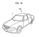
- Fig. 16 is a schematic perspective diagram illustrating an automobile, as an example of a mobile object which includes an angular velocity sensor.
- An automobile 1500 uses the angular velocity sensor 1 (or either 2 or 3), as a navigation device which is mounted thereon, or a posture detection sensor for a posture control device.
- the automobile 1500 includes the above-described angular velocity sensor, and thus the effects which are described in the first embodiment, the modification example, and the second embodiment are obtained, and excellent performance can be exhibited.
- the above-described angular velocity sensor is not limited to being applied to the automobile 1500, and can be preferably applied to a posture detection sensor, or the like, of a mobile object including a self-propelled robot, a self-propelled transport device, a train, a ship, an airplane, a satellite, or the like. It is possible to provide a mobile object in which the effects which are described in the first embodiment, the modification example, and the second embodiment are obtained, and excellent performance is exhibited.
Landscapes
- Physics & Mathematics (AREA)
- Engineering & Computer Science (AREA)
- General Physics & Mathematics (AREA)
- Radar, Positioning & Navigation (AREA)
- Remote Sensing (AREA)
- Gyroscopes (AREA)
- Micromachines (AREA)
- Pressure Sensors (AREA)
Abstract
Description
- The present invention relates to an angular velocity sensor, an electronic apparatus and a mobile object which include the angular velocity sensor.
- In the related art, a gyroscope (hereinafter, referred to as an angular velocity sensor) with a configuration in which a plurality of drive masses (hereinafter, referred to as mass units) disposed on a substrate as an angular velocity sensor corresponding to angular velocities of three detection axis rotations are coupled to each other by elastic coupling elements (hereinafter, referred to as coupling units), at least one mass unit is subjected to drive movement (hereinafter, referred to as drive vibration) by a drive unit, and thereby the drive vibration is transferred to another mass unit through the coupling unit, further, in a state in which a plurality of mass units is subjected to the drive vibration, angular velocity which is applied thereto is detected using detection vibration of detection units which are provided in a plurality of mass units, is known (for example, refer to European Patent Application Publication No.
2339293 ). - In an embodiment, the angular velocity sensor has a configuration in which two mass units (hereinafter, referred to as first mass pair) are subjected to drive vibration directly by a drive unit, thereby the drive vibration is transferred with a given rate to the other two mass units (hereinafter, referred to as second mass pair) through a coupling unit, and a total of four mass units is subjected to the drive vibration.
- However, there is a possibility that, in the angular velocity sensor, the given rate may not be approximately 1:1 due to consumption of drive vibration energy or the like caused by, for example, a coupling unit having elasticity.
- For this reason, there is a possibility that, in the angular velocity sensor, an amplitude of the drive vibration of the second mass pair to which the drive vibration is transferred from the first mass pair through the coupling unit may be smaller than an amplitude of the first mass pair which is subjected to drive vibration directly by a drive unit.
- As a result, there is a possibility that, in the angular velocity sensor, an amplitude of detection vibration of a detection unit of the second mass pair at the time of applying angular velocity may be smaller than an amplitude of a detection unit of the first mass pair, and thus there may be a difference between detection sensitivities of detection axis rotation of each of three detection axis rotation angular velocities which are detected by detection units of the four mass units.
- Due to this, there is a possibility that detection characteristics of the angular velocity sensor may be degraded.
- An advantage of some aspects of the invention can be realized by the following forms or application examples. Application Example 1
- According to this application example, there is provided an angular velocity sensor including a substrate; a plurality of mass units which is disposed on the substrate; coupling units which couple the mass units that are adjacent to each other, among the plurality of mass units; and drive units which are disposed on the substrate and are connected to the coupling units, in which the drive units respectively drive the mass units that are adjacent to each other through the coupling units.
- In this application example, the angular velocity sensor includes the coupling units which couple the mass units that are adjacent to each other, and the moving units which are connected to the coupling units. Also, the drive units respectively drive the mass units that are adjacent to each other through the coupling units.
- By doing this, the angular velocity sensor can substantially equally drive the mass units that are adjacent to each other, and thus it is possible to make an amount of displacement (for example, amplitude of drive vibration) of the mass units at the time of driving substantially equal to each other.
- As a result, for example, the angular velocity sensor can make an amount of displacement (for example, amplitude of detection vibration) of the mass units at the time of detecting angular velocity substantially equal to each other, and thus it is possible to reduce a difference of detection sensitivity of angular velocity between the respective detection axes.
- By doing this, the angular velocity sensor can improve detection characteristics of angular velocity. Application Example 2
- In the angular velocity sensor according to the application example, it is preferable that the plurality of mass units includes a first mass pair in which two of the mass units are disposed so as to face each other along a first axis, and a second mass pair in which the other two of the mass units are disposed so as to face each other along a second axis that intersects the first axis in a planar view. Also, it is preferable that the drive units drive the respective mass units such that the second mass pair is displaced in a direction that separates the pair from each other, when the first mass pair is displaced in a direction that brings the pair toward each other, and such that the second mass pair is displaced in a direction that brings the pair toward each other, when the first mass pair is displaced in a direction that separates the pair from each other.
- In this example, the drive units of the angular velocity sensor drive the respective mass units such that the second mass pair is displaced in a direction that separates the pair from each other, when the first mass pair is displaced in a direction that brings the pair toward each other, and such that the second mass pair is displaced in a direction that brings the pair toward each other, when the first mass pair is displaced in a direction that separates the pair from each other.
- As a result, the displacement method (in other words, vibration mode of drive vibration) of the respective mass units at the time of driving is defined by the drive unit, and thus, for example, the angular velocity sensor can suppress generation of an unnecessary vibration mode at the time of driving.
- By doing this, for example, the angular velocity sensor can omit or simplify a frequency control used for limiting the unnecessary vibration mode.
- In the angular velocity sensor according to the application example, it is preferable that at least the one of mass units of the first mass pair includes a first detection unit which detects angular velocity of a second axis rotation, at least the one of mass units of the second mass pair includes a second detection unit which detects angular velocity of a first axis rotation, and at least one mass unit of at least the one of the first mass pair and the second mass pair includes a third detection unit which detects angular velocity of a third axis rotation which intersects a flat plane along the first axis and the second axis.
- In this application example, the angular velocity sensor can reduce a difference in detection sensitivity between the respective detection axes (first axis to third axis) using the respective detection units and can detect the angular velocity of three detection axis rotations. Application Example 4
- In the angular velocity sensor according to the application example, it is preferable that at least one of the plurality of mass units includes a monitoring unit which monitors displacement of the mass unit at the time of driving.
- In this application example, since at least one of the mass units includes a monitoring unit which monitors displacement of the mass unit at the time of driving, the angular velocity sensor can maintain an amount of displacement at the time of driving the respective mass units at a predetermined level, for example, by electromechanically converting the displacement, amplifying the displacement, and applying the displacement to the drive unit.
- As a result, drive states of the respective mass units become stable, and thus the angular velocity sensor can improve the detection characteristics of angular velocity.
- In the angular velocity sensor according to the application example, it is preferable that the coupling unit is formed in an arc shape having the center thereof between the mass units that are adjacent to each other, the drive unit includes a fixing unit that includes the center of the arc shape and is fixed to the substrate and a moving unit which connects the fixing unit to the coupling unit, and the moving unit and the coupling unit can rotate using the fixing unit as the center thereof.
- In this application example, the coupling unit of the angular velocity sensor is formed in an arc shape, the angular velocity sensor includes a drive unit including a fixing unit which is fixed on the substrate, and a moving unit which connects the fixing unit to the coupling unit, and the moving unit and the coupling unit can rotate using the fixing unit as the center thereof.
- As a result, in the angular velocity sensor, the drive unit can smoothly drive the respective mass units through the coupling unit.
- In the angular velocity sensor according to the application example, it is preferable that the drive unit includes a fixing electrode which is provided on the substrate and a moving electrode which is provided in the moving unit, the fixing electrode and the moving electrode include electrode fingers which mesh with each other and have a comb tooth shape, and the electrode fingers are formed in an arc shape having the fixing unit as the center thereof.
- In this application example, the fixing electrode and the moving electrode of the drive units include electrode fingers of a comb shape meshing with each other, the electrode fingers are formed in an arc shape using the fixing unit as the center thereof, and thus the angular velocity sensor can smoothly rotate the moving unit and the coupling unit using the fixing unit as the center thereof. Application Example 7
- In the angular velocity sensor according to the application example, it is preferable that the coupling unit includes a stress reduction unit in a connection unit between the coupling unit and the mass unit.
- In this application example, the coupling unit includes a stress reduction unit in a connection unit between the coupling unit and the mass unit, and thus, the angular velocity sensor can reduce concentration of the stress occurring in the connection unit between the coupling unit and the mass unit at the time of driving.
- According to this application example, there is provided an electronic apparatus including the angular velocity sensor which is described in any one of the application examples.
- In this application example, an electronic apparatus of the present configuration includes the angular velocity sensor which is described in any one of the above-described application examples, and thus an electronic apparatus which obtains the effects that are described in any one of the above-described application examples can be provided.
- According to this application example, there is provided a mobile object including the angular velocity sensor which is described in any one of the application examples.
- In this application example, a mobile object of the present configuration includes the angular velocity sensor which is described in any one of the above-described application examples, and thus a mobile object which obtains the effects that are described in any one of the above-described application examples can be provided.
- The invention will be described with reference to the accompanying drawings, wherein like numbers reference like elements.
-
Fig. 1 is a schematic plan diagram illustrating a schematic configuration of an angular velocity sensor according to a first embodiment. -
Fig. 2 is an enlarged schematic plan diagram of one essential unit ofFig. 1 . -
Fig. 3A is an enlarged schematic plan diagram of another essential unit ofFig. 1 .Fig. 3B is a schematic cross-sectional diagram cut along line IIIB-IIIB ofFig. 3A . -
Fig. 4A is an enlarged schematic plan diagram of still another essential unit ofFig. 1 .Fig. 4B is a schematic cross-sectional diagram cut along line IVB-IVB ofFig. 4A . -
Fig. 5 is a schematic plan diagram illustrating a drive vibration state of an angular velocity sensor. -
Figs. 6A and 6B are schematic diagrams illustrating a method of adding force to an angular velocity sensor in a drive vibration state. -
Fig. 7 is a block diagram illustrating a function of a monitoring unit which monitors a drive vibration state of an angular velocity sensor. -
Fig. 8 is a schematic plan diagram illustrating a detection vibration state of detecting an X-axis rotation angular velocity of an angular velocity sensor. -
Fig. 9 is a schematic plan diagram illustrating a detection vibration state of detecting a Y-axis rotation angular velocity of an angular velocity sensor. -
Fig. 10 is a schematic plan diagram illustrating a detection vibration state of detecting a Z-axis rotation angular velocity of an angular velocity sensor. -
Fig. 11 is a schematic plan diagram illustrating a schematic configuration of an angular velocity sensor of a modification example according to the first embodiment. -
Fig. 12 is a schematic plan diagram illustrating a schematic configuration of an angular velocity sensor according to a second embodiment. -
Fig. 13 is a schematic perspective diagram illustrating a configuration of a personal computer of a mobile type (or notebook type) which functions as an electronic apparatus including an angular velocity sensor. -
Fig. 14 is a schematic perspective diagram illustrating a configuration of a mobile phone (also including PHS) which functions as an electronic apparatus including an angular velocity sensor. -
Fig. 15 is a schematic perspective diagram illustrating a configuration of a digital still camera which functions as an electronic apparatus including an angular velocity sensor. -
Fig. 16 is a schematic perspective diagram illustrating an automobile, as an example of a mobile object which includes an angular velocity sensor. - Hereinafter, embodiments in which the invention is specified will be described with reference to the drawings.
- An angular velocity sensor according to a first embodiment will be first described.
-
Fig. 1 is a schematic plan diagram illustrating a schematic configuration of an angular velocity sensor according to a first embodiment.Figs. 2 to 4B are enlarged schematic diagrams of essential units ofFig. 1 ,Fig. 2 is an enlarged schematic plan diagram of one essential portion ofFig. 1 ,Fig. 3A is an enlarged schematic plan diagram of another essential portion ofFig. 1 , andFig. 3B is a schematic cross-sectional diagram cut along line IIIB-IIIB ofFig. 3A . In addition,Fig. 4A is an enlarged schematic plan diagram of still another essential portion ofFig. 1 , andFig. 4B is a schematic cross-sectional diagram cut along line IVB-IVB ofFig. 4A . In the figures, an X axis, a Y axis, and a Z axis are coordinate axes which are orthogonal to each other, and the direction of an arrow is a + (plus) direction. - As illustrated in
FIG. 1 , anangular velocity sensor 1 includes asubstrate 10 of an approximately flat plate shape, afirst mass unit 21, asecond mass unit 22, athird mass unit 23, and afourth mass unit 24 which are a plurality (here, four) of mass units that are disposed on thesubstrate 10,coupling units 31 to 34 which respectively couple thefirst mass unit 21 and thethird mass unit 23, thethird mass unit 23 and thesecond mass unit 22, thesecond mass unit 22 and thefourth mass unit 24, and thefourth mass unit 24 and thefirst mass unit 21 which are adjacent to each other, among the plurality of mass units, and driveunits 41 to 44 which are disposed on thesubstrate 10 and are connected to thecoupling units 31 to 34. - The plurality of mass units includes a first mass pair A in which the
first mass unit 21 and thesecond mass unit 22 which are two mass units are disposed in a facing manner along the X axis which is defined as a first axis, and a second mass pair B in which thethird mass unit 23 and thefourth mass unit 24, which are another two mass units, are disposed in a facing manner along the Y axis which is defined as a second axis which intersects (here, orthogonal) the X axis in a planar view. - The
respective mass units 21 to 24 are formed in an approximately rectangular shape, and end portions opposite to end portions which are connected to therespective coupling units 31 to 34 are connected to the fixingunits 51 which protrude from thesubstrate 10 through aspring unit 50. - The
spring units 50 are provided as a pair in the end portions of therespective mass units 21 to 24. In the first mass pair A, the spring units protrude in the Y-axis direction and extend in the X-axis direction thereby being connected to the fixingunits 51, and in the second mass pair B, the spring units protrude in the X-axis direction and extend in the Y-axis direction thereby being connected to the fixingunits 51. - By doing this, the first mass pair A can be displaced in the X-axis direction by deflection (deformation) of the
spring unit 50, and the second mass pair B can be displaced in the Y-axis direction in the same manner. A predetermined gap is provided between therespective mass units 21 to 24 and thesubstrate 10, in order to avoid interference at the time of displacement(for example, a concave portion which is not illustrated in thesubstrate 10 is provided). - The
coupling units 31 to 34 are formed in arc shapes which respectively have centers O1 to 04, between thefirst mass unit 21 and thethird mass unit 23, between thethird mass unit 23 and thesecond mass unit 22, between thesecond mass unit 22 and thefourth mass unit 24, and between thefourth mass unit 24 and thefirst mass unit 21, which are mass units that are adjacent to each other. - The
respective drive units 41 to 44 include a fixingunit 45 which includes the respective centers O1 to 04 of the arcs and are fixed to thesubstrate 10, and a movingunit 46 which connects the fixingunit 45 to therespective coupling units 31 to 34. - The
respective drive units 41 to 44 are configured to be able to rotate the movingunit 46 and therespective coupling units 31 to 34 using the fixingunit 45 as the center thereof. - More specifically, as illustrated in
Fig. 2 , therespective drive units 41 to 44 include a pair of fixingelectrodes 47 which are provided on thesubstrate 10 so as to interpose the movingunit 46 between the fixingelectrodes 47, and a movingelectrode 48 which is provided in the movingunit 46. - The fixing
electrode 47 and the movingelectrode 48 include comb-shapedelectrode fingers electrode fingers unit 45 as the center thereof. - By doing this, the fixing
electrode 47 and the movingelectrode 48 are spread in a fan shape using the fixingunit 45 as the center thereof. - The
respective drive units 41 to 44 apply a voltage between the fixingelectrode 47 and the movingelectrode 48 using, for example, a drive circuit which is not illustrated, and can alternately rotate the movingunit 46 and therespective coupling units 31 to 34 using electrostatic drive caused by electrostatic force (electrostatic attractive force, electrostatic repulsive force) between the fixingelectrode 47 and the movingelectrode 48, in a clockwise direction (white arrow direction) and a counter-clockwise direction (black arrow direction) using the fixingunit 45 as the center thereof. - Returning to
Fig. 1 , it is preferable that thefirst mass unit 21 and thesecond mass unit 22 are symmetrically shaped with respect to a straight line along the Y axis which passes between thefirst mass unit 21 and thesecond mass unit 22, and thethird mass unit 23 and thefourth mass unit 24 are symmetrically shaped with respect to a straight line along the X axis which passes between thethird mass unit 23 and thefourth mass unit 24. - The
first mass unit 21 and thesecond mass unit 22 which are at least one (here, two) mass unit of the first mass pair A includefirst detection units third mass unit 23 and thefourth mass unit 24 which are at least one (here, two) mass unit of the second mass pair B includesecond detection units - Furthermore, the
first mass unit 21 and thesecond mass unit 22 which are at least one (here, two) mass unit of at least one (here, the first mass pair A) of the first mass pair A and the second mass pair B includethird detection units - Additionally, at least one (here, two units which are the
third mass unit 23 and the fourth mass unit 24) of themass units 21 to 24 includesmonitoring units third mass unit 23 and thefourth mass unit 24 at the time of driving. - More specifically, as illustrated in
Figs. 3A and 3B , thefirst mass unit 21 and thesecond mass unit 22 of the first mass pair A includeframe units Figs. 3A and 3B represent symbols of the second mass unit 22) of a rectangular frame shape, thefirst detection units frame units third detection units frame units first detection units - The
first detection units frame units spring units 52. - The fixing
electrode 11 which is larger than thefirst detection units first detection units substrate 10. - In such a manner that the
first detection units spring units 52 are respectively positioned in an end portion on a +Y side and in an end portion on a - (negative) Y side of thefirst detection units first detection units - As illustrated in
Fig. 3B , thefirst detection units electrode 11 and thefirst detection units first detection units - The
third detection units frame units spring units 53. - On the
substrate 10, fixingelectrodes third detection units - In such a manner that the
third detection units spring units 53 extend in the Y-axis direction while protruding in the X-axis direction, and connect an end portion on a +Y side and an end portion of -Y side of thethird detection units frame units - The
third detection units electrodes third detection units third detection units - As illustrated in
Figs. 4A and 4B , thethird mass unit 23 and thefourth mass unit 24 of the second mass pair B includeframe units Figs. 4A and 4B represent symbols of the fourth mass unit 24) of a rectangular frame shape, thesecond detection units frame units monitoring units frame units second detection units third mass unit 23 and thefourth mass unit 24 at the time of driving. - The
second detection units frame units spring units 54. - The fixing
electrode 12 which is larger than thesecond detection units second detection units substrate 10. - In such a manner that the
second detection units spring units 54 are formed in a crank shape which is the same as thespring units 52, and connect an end portion extending along the X axis of thesecond detection units frame units - As illustrated in
Fig. 4B , thesecond detection units electrode 12 and thesecond detection units second detection units - The
monitoring units frame units - The fixing
electrodes substrate 10, so as to interpose the beam shape portion of themonitoring units - The
monitoring units electrodes - The
monitoring units electrodes monitoring units - It is preferable to use an insulating material, such as glass or high-resistivity silicon, as a configuration material of the
substrate 10. Particularly, in a case in which an element plate that overlaps thesubstrate 10 and is attached to therespective mass units 21 to 24, therespective coupling units 31 to 34, therespective drive units 41 to 44, thespring unit 50, the fixingunit 51, or the like using etching or the like, is a semiconductor element plate that is configured to use a semiconductor material such as silicon as a main material, it is preferable to use glass (borosilicate glass, for example, Pyrex (registered trademark)) containing alkali metal ions (moving ion) as a configuration material of thesubstrate 10. - By doing this, the
angular velocity sensor 1 can anodically bond thesubstrate 10 to the semiconductor element plate. In addition, theangular velocity sensor 1 uses glass containing alkali metal ions for thesubstrate 10, and therefore thesubstrate 10 and the semiconductor element plate can be easily separated in an insulating manner. - The
substrate 10 may not have insulation properties, and for example, may be a conductive substrate which is configured of a low-resistivity silicon. In this case, an insulating film is interposed between thesubstrate 10 and the semiconductor element plate, and thereby both are separated in an insulating manner. - It is preferable that thermal expansion coefficient difference between the configuration material of the
substrate 10 and the configuration material of the semiconductor element plate is as small as possible. Specifically, it is preferable that the thermal expansion coefficient difference between the configuration material of thesubstrate 10 and the configuration material of the semiconductor element plate is equal to or less than 3 ppm/°C. By doing this, theangular velocity sensor 1 can reduce residual stress between thesubstrate 10 and the semiconductor element plate. - Hereafter, an operation of the
angular velocity sensor 1 will be described. -
Fig. 5 is a schematic plan diagram illustrating a drive vibration state of the angular velocity sensor,Fig. 6A and Fig. 6B are schematic diagrams illustrating a force-adding method of the drive vibration state of the angular velocity sensor, andFig. 7 is a block diagram illustrating a function of the monitoring unit which monitors the drive vibration state of the angular velocity sensor. - In addition,
Fig. 8 is a schematic plan diagram illustrating a detection vibration state of detecting the X-axis rotation angular velocity of the angular velocity sensor,Fig. 9 is a schematic plan diagram illustrating a detection vibration state of detecting the Y-axis rotation angular velocity of the angular velocity sensor, andFig. 10 is a schematic plan diagram illustrating a detection vibration state of detecting the Z-axis rotation angular velocity of the angular velocity sensor. - As illustrated in
Fig. 5 , in theangular velocity sensor 1, for example, if the drive signals are applied to therespective drive units 41 to 44 from a drive circuit which is not illustrated, therespective drive units 41 to 44 alternately rotate therespective coupling units 31 to 34 in a black arrow direction and a white arrow direction, such that the second mass pair B (thethird mass unit 23 and the fourth mass unit 24) is displaced in a direction that separates the pair from each other (black arrow), when the first mass pair A (thefirst mass unit 21 and the second mass unit 22) is displaced in a direction that brings the pair toward each other, and such that the second mass pair B is displaced in a direction that brings the pair toward each other (white arrow), when the first mass pair A is displaced in a direction that separates the pair from each other. Thereby, therespective mass units 21 to 24 are driven (drive vibration is performed). - Here, a method of adding force from the
respective coupling units 31 to 34 to therespective mass units 21 to 24 will be described. Here, an example in which thefirst mass unit 21 is representatively used will be described, but the othermass units 22 to 24 may be respectively used in the same manner as thefirst mass unit 21. - As illustrated in
Fig. 6A , if thecoupling units first mass unit 21 in an oblique -X direction along tangent lines of end portions of thecoupling units - At this time, a component force F1y which is a component force along the Y axis of the force F1, and a component force F2y which is a component force along the Y axis of the force F2 are equal in magnitude and are opposite directionally, thereby cancelling one another.
- Meanwhile, a component force F1x which is a component force along the X axis of the force F1, and a component force F2x which is a component force along the X axis of the force F2 are equal in magnitude and are applied in the same direction, and therefore are added to each other along the X axis. The
first mass unit 21 is displaced in the white arrow direction along the X axis. - As illustrated in
Fig. 6B , if thecoupling units first mass unit 21 in a direction opposite to the forces F1 and F2 along tangent lines of end portions of thecoupling units - At this time, a component force F1'y which is a component force along the Y axis of the force F1', and a component force F2'y which is a component force along the Y axis of the force F2' are equal in magnitude and are opposite in direction, and therefore cancel one another.
- Meanwhile, a component force F1'x which is a component force along the X axis of the force F1', and a component force F2'x which is a component force along the X axis of the force F2' are equal in magnitude and are also applied in the same direction, and therefore are added to each other along the X axis. The
first mass unit 21 is displaced in the black arrow direction along the X axis. - By doing this, as illustrated in
Fig. 5 , therespective mass units 21 to 24 are subjected to alternate and repetitive drive vibration of the displacement in the white arrow direction and the displacement in the black arrow direction. - At this time, the
monitoring units Fig. 4A monitor displacement in the Y-axis direction of thethird mass unit 23 and thefourth mass unit 24 as a change of capacitance between the fixingelectrodes monitoring units - As illustrated in
Fig. 7 , theangular velocity sensor 1 amplifies the change of capacitance which is monitored by themonitoring units amplification circuit 70 which uses, for example, an operational amplifier or the like, and the change of capacitance is controlled by an automatic gain control (AGC)circuit 71 or the like at a predetermined level, and is applied (feedback) to adrive circuit 72. - Drive forces of the
respective drive units 41 to 44 are increased by this loop, and theangular velocity sensor 1 is configured to be able to maintain an amount of displacement at the time of driving therespective mass units 21 to 24 at a predetermined level. - As illustrated in
Fig. 8 , in the above-described drive vibration state, if an angular velocity ω is applied to an X-axis rotation, thesecond detection units Figs. 4A and 4B , of thethird mass unit 23 and thefourth mass unit 24 perform detection vibrations of alternately repeating the displacement (displacement in the white arrow direction ofFig. 4B ) in a +Z direction and the displacement (displacement in the black arrow direction ofFig. 4B ) in a -Z direction. "●" in "○" inFig. 8 represents the displacement in the +Z direction, and "x" in "○" inFig. 8 represents the displacement in the -Z direction. - In detail, the detection vibration is performed in which, if the
second detection unit 62a is displaced in the +Z direction, thesecond detection unit 62b is displaced in the -Z direction, and if thesecond detection unit 62a is displaced in the -Z direction, thesecond detection unit 62b is displaced in the +Z direction. - The
angular velocity sensor 1 can draw the X-axis rotation angular velocity by taking out a differential change amount of capacitance depending on the above-described displacement of thesecond detection units - As illustrated in
Fig. 9 , in the above-described drive vibration state, if an angular velocity ω is applied to an Y-axis rotation, thefirst detection units Figs. 3A and 3B , of thefirst mass unit 21 and thesecond mass unit 22 perform detection vibrations of alternately repeating the displacement (displacement in the white arrow direction ofFig. 3B ) in a +Z direction and the displacement (displacement in the black arrow direction ofFig. 3B ) in a -Z direction. "●" in "○" inFig. 9 represents the displacement in the +Z direction, and "x" in "○" inFig. 9 represents the displacement in the -Z direction. - In detail, the detection vibration is performed in which, if the
first detection unit 61a is displaced in the +Z direction, thefirst detection unit 61b is displaced in the -Z direction, and if thefirst detection unit 61a is displaced in the -Z direction, thefirst detection unit 61b is displaced in the +Z direction. - The
angular velocity sensor 1 can draw the Y-axis rotation angular velocity by taking out a differential change amount of capacitance depending on the above-described displacement of thefirst detection units - The As illustrated in
Fig. 10 , in the above-described drive vibration state, if an angular velocity ω is applied to an Z-axis rotation, thethird detection units Fig. 3A , of thefirst mass unit 21 and thesecond mass unit 22 perform detection vibrations of alternately repeating displacement in the +Y direction and displacement in the -Y direction along the Y axis. - In detail, the detection vibration is performed in which, if the
third detection unit 63a is displaced in the +Y direction, thethird detection unit 63b is displaced in the -Y direction (white arrow), and if thethird detection unit 63a is displaced in the -Y direction, thethird detection unit 63b is displaced in the +Y direction (black arrow). - The
angular velocity sensor 1 can draw the Z-axis rotation angular velocity by taking out a change of capacitance depending on the above-described displacement of thethird detection units - As described above, the
angular velocity sensor 1 according to the first embodiment includes the coupling unit (31 or the like) which couples the mass units (thefirst mass unit 21, thethird mass unit 23, and the like) that are adjacent to each other, and therespective drive units 41 to 44 which are connected to therespective coupling units 31 to 34. Therespective drive units 41 to 44 respectively drive the mass units (thefirst mass unit 21, thethird mass unit 23, and the like) that are adjacent to each other through therespective coupling units 31 to 34. - In contrast to this, the angular velocity sensor which is disclosed in European Patent Application Publication No.
2339293 which is an example of related art transfers the drive vibration from the first mass pair to the second mass pair through the coupling unit, and thus when the drive vibration of the four mass units is performed, an unnecessary vibration mode different from an original vibration mode is easily generated, and thus, it is necessary to perform frequency control for limiting the unnecessary vibration mode. - The
angular velocity sensor 1 according to the embodiment can drive in substantially the same manner as each other the mass units (thefirst mass unit 21, thethird mass unit 23, and the like) that are adjacent to each other, and thus it is possible to make the amounts of displacement (amplitude at the time of drive vibration) of therespective mass units 21 to 24 at the time of driving approximately equal to each other. - As a result, the
angular velocity sensor 1 can make the amounts of displacement (amplitude of detection vibration) of therespective mass units 21 to 24, for example, at the time of detecting angular velocity approximately equal to each other, and thus it is possible to decrease a difference of a detection sensitivity between the respective detection axes (X axis, Y axis, and Z axis) of the angular velocity ω. - By doing this, the
angular velocity sensor 1 can improve detection characteristics of the angular velocity ω. - In addition, for the
angular velocity sensor 1, therespective drive units 41 to 44 are subjected to drive vibration of therespective mass units 21 to 24 (herein, the drive vibration form (vibration mode) is referred to as an alternative mode), such that the second mass pair B is displaced in a direction that separates the pair from each other, when the first mass pair A is displaced in a direction that brings the pair toward each other, and such that the second mass pair B is displaced in a direction that brings the pair toward each other, when the first mass pair A is displaced in a direction that separates the pair from each other. - As a result, in the
angular velocity sensor 1, a vibration mode of the drive vibration of therespective mass units 21 to 24 is defined as an alternative mode by therespective drive units 41 to 44, and thus it is possible to suppress generation of an unnecessary vibration mode other than the alternative mode at the time of driving. - By doing this, the
angular velocity sensor 1 can suppress a malfunction caused by the unnecessary vibration mode, or can simplify means for suppressing the unnecessary vibration mode. - In addition, the
angular velocity sensor 1 can reduce a difference of detection sensitivity between the respective detection axes (X axis, Y axis, and Z axis) using thefirst detection units second detection units third detection units respective mass units 21 to 24, and can detect each angular velocity ω of the three detection axis rotations. - In addition, for the
angular velocity sensor 1, at least one (herein, two units of thethird mass unit 23 and the fourth mass unit 24) of therespective mass units 21 to 24 includes themonitoring units third mass unit 23 and thefourth mass unit 24 at the time of driving. - Because of this, the
angular velocity sensor 1 can maintain an amount of displacement at the time of driving therespective mass units 21 to 24 at a predetermined level, by electromechanically converting (herein, converting into capacitance) the displacement, amplifying the displacement using theamplification circuit 70, controlling the displacement to a predetermined level using theAGC circuit 71 or the like, and applying the displacement to therespective drive units 41 to 44 through thedrive circuit 72. - As a result, the drive states of the
respective mass units 21 to 24 are stable, and thus theangular velocity sensor 1 can improve the detection characteristics of the angular velocity ω. - In addition, in the
angular velocity sensor 1, therespective coupling units 31 to 34 are formed in an arc shape, therespective drive units 41 to 44 includes the fixingunit 45 which and is fixed to thesubstrate 10 and the movingunit 46 which couples the fixingunit 45 to therespective coupling units 31 to 34. The movingunit 46 and therespective coupling units 31 to 34 can rotate using the fixingunit 45 as the center thereof. - As a result, in the
angular velocity sensor 1, therespective drive units 41 to 44 can smoothly drive therespective mass units 21 to 24 through therespective coupling units 31 to 34. - In addition, the fixing
electrodes 47 and the movingelectrodes 48 of therespective drive units 41 to 44 includeelectrode fingers electrode fingers unit 45 as the center thereof, and thus theangular velocity sensor 1 can smoothly rotate the movingunit 46 and therespective coupling units 31 to 34 using the fixingunit 45 as the center thereof. - Next, an angular velocity sensor of a modification example according to the first embodiment will be described.
-
Fig. 11 is a schematic plan diagram illustrating a schematic configuration of an angular velocity sensor of a modification example according to the first embodiment. The same symbols or reference numerals will be attached to the same configurations as in the first embodiment, detailed description thereof will be omitted, and configurations different from those of the first embodiment will be mainly described. - As illustrated in
Fig. 11 , an angular velocity sensor 2 of the modification example includes therespective coupling units 31 to 34 having different configurations from those of the first embodiment. - The angular velocity sensor 2 includes
stress reduction units 31a to 34a in the connection units between therespective coupling units 31 to 34 and therespective mass units 21 to 24. - The respective
stress reduction units 31a to 34a meander in directions intersecting extending directions of therespective coupling units 31 to 34, or are formed in a protruding and meandering shape. - By doing this, stress occurring in the connection units between the
respective coupling units 31 to 34 and therespective mass units 21 to 24 at the time of driving are dispersed into the respectivestress reduction units 31a to 34a, and thus the angular velocity sensor 2 can reduce concentration of the stress. - As a result, durability of the
respective coupling units 31 to 34 is improved, and thus the angular velocity sensor 2 can increase reliability. - This configuration can also be applied to the following embodiments.
-
Fig. 12 is a schematic plan diagram illustrating a schematic configuration of an angular velocity sensor according to a second embodiment. The same symbols or reference numerals will be attached to the same configurations as in the first embodiment, detailed description thereof will be omitted, and configurations different from those of the first embodiment will be mainly described. - As illustrated in
Fig. 12 , anangular velocity sensor 3 according to the second embodiment has different drive directions of therespective drive units 41 to 44 from those of the first embodiment. - In the
angular velocity sensor 3, the fixingunit 45 is provided in an intersecting portion at which a line connecting the first mass pair A to each other intersects a line connecting the second mass pair B, and the movingunit 46 is connected to therespective coupling units 31 to 34 from the fixingunit 45 through adisplacement absorption unit 46a which is formed in a meandering shape. - Furthermore, the moving
unit 46 extends to areas of the fixingelectrode 47 and the movingelectrode 48 of therespective drive units 41 to 44 from therespective coupling units 31 to 34. The movingunit 46 extends in a straight line shape at an angle of approximately 45 degrees with respect to the X axis or the Y axis. - The
displacement absorption unit 46a does not interfere with a linear reciprocating motion, which will be described later, of the movingunit 46 for the meandering shape, and is connected to the fixingunit 45, thereby supporting the movingunit 46. - The
respective coupling units 31 to 34 extend toward the fixingunit 45 side along an extending direction of therespective mass units 21 to 24, and are bent in directions orthogonal to the movingunit 46 from the middle, and thereby the mass units (thefirst mass unit 21 and the third mass unit 23) that are adjacent to each other are coupled together. - The shapes of the
respective coupling units 31 to 34 are not limited to the above-described shape, and may be the same shapes as those of the first embodiment. - The
respective drive units 41 to 44 are provided in a shape in which the fixingelectrode 47 and the movingelectrode 48 are meshed in parallel in a direction in which comb teeth are orthogonal to an extending direction of the movingunit 46, for example, as illustrated, such that the movingunit 46 performs a straight reciprocating motion (alternate displacement in a white arrow direction and a black arrow direction) along an extending direction. - By doing this, in a drive vibration state, the
angular velocity sensor 3 can perform drive vibration of alternately repeating displacement in the white arrow direction and displacement in the black arrow direction, such that the second mass pair B (thethird mass unit 23 and the fourth mass unit 24) is displaced (white arrow) in a direction that brings the pair toward each other, when the first mass pair A (thefirst mass unit 21 and the second mass unit 22) is displaced (white arrow) in a direction that brings the pair toward each other, and such that the second mass pair B is displaced (black arrow) in a direction that separates the pair from each other, when the first mass pair A is displaced (black arrow) in a direction that separates the pair from each other. - Herein, the vibration mode is referred to as an expansion mode.
- As described above, for the
angular velocity sensor 3, a vibration mode of a drive vibration is an expansion mode different from the alternative mode according to the first embodiment, but is the same as in the first embodiment in the detection vibration, and thus, description with regard to an operation at the time of applying angular velocity will be omitted. - The
angular velocity sensor 3 is configured as described above, and thus, drive levels of therespective mass units 21 to 24 through therespective coupling units 31 to 34 by therespective drive units 41 to 44, and detection levels of therespective detection units - In addition, a vibration mode is defined by an expansion mode, and thus the
angular velocity sensor 3 can suppress the occurrence of an unnecessary vibration mode other than the expansion mode at the time of driving. - As a result, the
angular velocity sensor 3 can obtain the same effect as that of the first embodiment. Electronic Apparatus - Next, an electronic apparatus including the above-described angular velocity sensor will be described.
-
Fig. 13 is a schematic perspective diagram illustrating a configuration of a personal computer of a mobile type (or notebook type) which functions as an electronic apparatus including an angular velocity sensor. - As illustrated in
Fig. 13 , apersonal computer 1100 is configured of abody unit 1104 including akey board 1102, and adisplay unit 1106 including adisplay unit 1101. Thedisplay unit 1106 is supported so as to be able to rotate via a hinge structure with respect to thebody unit 1104. - The angular velocity sensor 1 (or either 2 or 3) is embedded in the
personal computer 1100. -
Fig. 14 is a schematic perspective diagram illustrating a configuration of a mobile phone (also including PHS) which functions as an electronic apparatus including an angular velocity sensor. - As illustrated in
Fig. 14 , amobile phone 1200 includes a plurality ofoperation buttons 1202, avoice receiving hole 1204, and avoice transmitting hole 1206. Adisplay unit 1201 is disposed between theoperation buttons 1202 and thevoice receiving hole 1204. - The angular velocity sensor 1 (or either 2 or 3) is embedded in the
mobile phone 1200. -
Fig. 15 is a schematic perspective diagram illustrating a configuration of a digital still camera which functions as an electronic apparatus including an angular velocity sensor. A connection to an external device is also illustrated in a simplifying manner inFig. 15 . - Here, a normal camera exposes a silver salt photographic film using an optical image of a subject. In contrast to this, a
digital still camera 1300 performs a photoelectric conversion of the optical image of the subject using an imaging element such as a charge coupled device (CCD), and generates an imaging signal (image signal). - A
display unit 1310 is provided on a rear surface (a front side in the figure) of a case (body) 1302 of thedigital still camera 1300, and is configured to perform display based on an imaging signal of the CCD. Thedisplay unit 1310 functions as a finder which displays a subject as an electronic image. - In addition, a
light receiving unit 1304 which includes an optical lens (imaging optical system), a CCD, or the like is provided on a front side (a far side in the figure) of acase 1302. - If a photographer checks a subject image which is displayed on the
display unit 1310 and pushes ashutter button 1306, an imaging signal of the CCD at that time is transferred to amemory 1308 and is stored there. - In addition, in the
digital still camera 1300, a videosignal output terminal 1312, and an input and output terminal fordata communication 1314 are provided on a side surface of acase 1302. Atelevision monitor 1430 is connected to the videosignal output terminal 1312, and apersonal computer 1440 is connected to the input and output terminal fordata communication 1314, as necessary. Furthermore, thedigital still camera 1300 is configured such that an imaging signal which is stored in thememory 1308 is output to thetelevision monitor 1430 or thepersonal computer 1440 through a predetermined operation. - The angular velocity sensor 1 (or either 2 or 3) is embedded in the
digital still camera 1300. - Such an electronic apparatus includes the above-described angular velocity sensor, and thus the effects which are described in the first embodiment, the modification example, and the second embodiment are obtained, and excellent performance can be exhibited.
- The electronic apparatus including the above-described angular velocity sensor can be used in, for example, an ink jet type ejecting device (for example, ink jet printer), a laptop type personal computer, a television, a video camera, a video tape recorder, various navigation device, a pager, an electronic notebook (including a communication function), an electronic dictionary, an electronic calculator, an electronic game machine, a word processor, a workstation, a videophone, security television monitor, electronic binoculars, a POS terminal, a medical apparatus (for example, an electronic thermometer, a blood pressure monitor, a blood glucose meter, an electrocardiogram measuring device, an ultrasonic diagnostic device, an electronic endoscope), a fish finder, various measuring instruments, gauges, a flight simulator, or the like.
- Next, a mobile object including the above-described angular velocity sensor will be described.
-
Fig. 16 is a schematic perspective diagram illustrating an automobile, as an example of a mobile object which includes an angular velocity sensor. - An
automobile 1500 uses the angular velocity sensor 1 (or either 2 or 3), as a navigation device which is mounted thereon, or a posture detection sensor for a posture control device. - Further, the
automobile 1500 includes the above-described angular velocity sensor, and thus the effects which are described in the first embodiment, the modification example, and the second embodiment are obtained, and excellent performance can be exhibited. - The above-described angular velocity sensor is not limited to being applied to the
automobile 1500, and can be preferably applied to a posture detection sensor, or the like, of a mobile object including a self-propelled robot, a self-propelled transport device, a train, a ship, an airplane, a satellite, or the like. It is possible to provide a mobile object in which the effects which are described in the first embodiment, the modification example, and the second embodiment are obtained, and excellent performance is exhibited.
Claims (19)
- An angular velocity sensor comprising:a substrate;a plurality of mass units which is disposed on the substrate;coupling units which couple the mass units that are adjacent to each other, among the plurality of mass units; anddrive units which are disposed on the substrate and are connected to the coupling units,wherein the drive units respectively drive the mass units that are adjacent to each other through the coupling units.
- The angular velocity sensor according to Claim 1,
wherein the plurality of mass units includes a first mass pair in which two of the mass units are disposed so as to face each other along a first axis, and a second mass pair in which the other two of the mass units are disposed so as to face each other along a second axis that intersects the first axis in a planar view, and
wherein the drive units drive the respective mass units such that the second mass pair is displaced in a direction that separates the pair from each other, when the first mass pair is displaced in a direction that brings the pair toward each other, and such that the second mass pair is displaced in a direction that brings the pair toward each other, when the first mass pair is displaced in a direction that separates the pair from each other. - The angular velocity sensor according to Claim 2,
wherein at least the one of mass units of the first mass pair includes a first detection unit which detects angular velocity of a second axis rotation,
wherein at least the one of mass units of the second mass pair includes a second detection unit which detects angular velocity of a first axis rotation, and
wherein at least one mass unit of at least the one of the first mass pair and the second mass pair includes a third detection unit which detects angular velocity of a third axis rotation which intersects a flat plane along the first axis and the second axis. - The angular velocity sensor according to any one of the preceding claims,
wherein at least one of the plurality of mass units includes a monitoring unit which monitors displacement of the mass unit at the time of driving. - The angular velocity sensor according to any one of the preceding claims,
wherein the coupling unit is formed in an arc shape having a center between the mass units that are adjacent to each other,
wherein the drive unit includes a fixing unit that includes the center of the arc shape and is fixed to the substrate, and a moving unit which connects the fixing unit to the coupling unit, and
wherein the moving unit and the coupling unit can rotate using the fixing unit as a center. - The angular velocity sensor according to Claim 5,
wherein the drive unit includes a fixing electrode which is provided on the substrate, and a moving electrode which is provided in the moving unit,
wherein the fixing electrode and the moving electrode include electrode fingers which mesh with each other and have a comb tooth shape, and
wherein the electrode fingers are formed in an arc shape having the fixing unit as a center. - The angular velocity sensor according to any one of the preceding claims,
wherein the coupling unit includes a stress reduction unit in a connection unit between the coupling unit and the mass unit. - The angular velocity sensor according to Claim 2,
wherein the coupling unit is formed in an arc shape having a center between the mass units that are adjacent to each other,
wherein the drive unit includes a fixing unit that includes the center of the arc shape and is fixed to the substrate, and a moving unit which connects the fixing unit to the coupling unit, and
wherein the moving unit and the coupling unit can rotate using the fixing unit as a center. - The angular velocity sensor according to Claim 8,
wherein the drive unit includes a fixing electrode which is provided on the substrate, and a moving electrode which is provided in the moving unit,
wherein the fixing electrode and the moving electrode include electrode fingers which mesh with each other and have a comb tooth shape, and
wherein the electrode fingers are formed in an arc shape having the fixing unit as a center. - The angular velocity sensor according to any one of Claims 2 to 9,
wherein the coupling unit includes a stress reduction unit in a connection unit between the coupling unit and the mass unit. - The angular velocity sensor according to Claim 3,
wherein the coupling unit is formed in an arc shape having a center between the mass units that are adjacent to each other,
wherein the drive unit includes a fixing unit that includes the center of the arc shape and is fixed to the substrate, and a moving unit which connects the fixing unit to the coupling unit, and
wherein the moving unit and the coupling unit can rotate using the fixing unit as a center. - The angular velocity sensor according to Claim 11,
wherein the drive unit includes a fixing electrode which is provided on the substrate, and a moving electrode which is provided in the moving unit,
wherein the fixing electrode and the moving electrode include electrode fingers which mesh with each other and have a comb tooth shape, and
wherein the electrode fingers are formed in an arc shape having the fixing unit as a center. - The angular velocity sensor according to Claim 3,
wherein the coupling unit includes a stress reduction unit in a connection unit between the coupling unit and the mass unit. - The angular velocity sensor according to Claim 4,
wherein the coupling unit is formed in an arc shape having a center between the mass units that are adjacent to each other,
wherein the drive unit includes a fixing unit that includes the center of the arc shape and is fixed to the substrate, and a moving unit which connects the fixing unit to the coupling unit, and
wherein the moving unit and the coupling unit can rotate using the fixing unit as a center. - The angular velocity sensor according to Claim 14,
wherein the drive unit includes a fixing electrode which is provided on the substrate, and a moving electrode which is provided in the moving unit,
wherein the fixing electrode and the moving electrode include electrode fingers which mesh with each other and have a comb tooth shape, and
wherein the electrode fingers are formed in an arc shape having the fixing unit as a center. - The angular velocity sensor according to any one of Claims 2 to 15,
wherein at least one of the plurality of mass units includes a monitoring unit which monitors displacement of the mass unit at the time of driving. - The angular velocity sensor according to any one of Claims 3 to 16,
wherein at least one of the plurality of mass units includes a monitoring unit which monitors displacement of the mass unit at the time of driving. - An electronic apparatus comprising:the angular velocity sensor according to any one of the preceding claims.
- A mobile object comprising:the angular velocity sensor according to any one of Claims 1 to 17.
Applications Claiming Priority (1)
| Application Number | Priority Date | Filing Date | Title |
|---|---|---|---|
| JP2014087981A JP6344033B2 (en) | 2014-04-22 | 2014-04-22 | Angular velocity sensor, electronic device and moving object |
Publications (3)
| Publication Number | Publication Date |
|---|---|
| EP2937667A2 true EP2937667A2 (en) | 2015-10-28 |
| EP2937667A3 EP2937667A3 (en) | 2016-02-17 |
| EP2937667B1 EP2937667B1 (en) | 2019-03-06 |
Family
ID=52997295
Family Applications (1)
| Application Number | Title | Priority Date | Filing Date |
|---|---|---|---|
| EP15164203.0A Not-in-force EP2937667B1 (en) | 2014-04-22 | 2015-04-20 | Angular velocity sensor, electronic apparatus, and mobile object |
Country Status (4)
| Country | Link |
|---|---|
| US (1) | US10119823B2 (en) |
| EP (1) | EP2937667B1 (en) |
| JP (1) | JP6344033B2 (en) |
| CN (1) | CN105043371A (en) |
Families Citing this family (10)
| Publication number | Priority date | Publication date | Assignee | Title |
|---|---|---|---|---|
| JP6248576B2 (en) * | 2013-11-25 | 2017-12-20 | セイコーエプソン株式会社 | Functional element, electronic device, and moving object |
| US10359284B2 (en) * | 2015-12-10 | 2019-07-23 | Invensense, Inc. | Yaw rate gyroscope robust to linear and angular acceleration |
| ITUA20162172A1 (en) * | 2016-03-31 | 2017-10-01 | St Microelectronics Srl | ACCELEROMETRIC SENSOR MADE IN MEMS TECHNOLOGY WITH HIGH ACCURACY AND REDUCED SENSITIVITY TOWARDS TEMPERATURE AND AGING |
| JP6639377B2 (en) | 2016-12-08 | 2020-02-05 | 株式会社東芝 | Vibration device |
| CN107192384B (en) * | 2017-07-24 | 2022-04-05 | 深迪半导体(绍兴)有限公司 | MEMS triaxial gyroscope |
| CN113494908B (en) * | 2020-03-19 | 2024-11-22 | 华为技术有限公司 | MEMS inertial sensors, inertial measurement units and inertial navigation systems |
| CN111998840B (en) * | 2020-08-28 | 2022-08-12 | 中电科技集团重庆声光电有限公司 | A MEMS multi-axis vibration sensor structure |
| CN114166197B (en) * | 2020-09-10 | 2024-05-31 | 无锡微元时代科技有限公司 | Four-mass double-decoupling Z-axis silicon micro gyroscope |
| IT202100020504A1 (en) | 2021-07-30 | 2023-01-30 | St Microelectronics Srl | MEMS GYROSCOPE HAVING IMPROVED SQUARE ERROR REJECTION |
| CN115355898B (en) * | 2022-07-15 | 2025-04-22 | 瑞声开泰科技(武汉)有限公司 | A fully decoupled three-axis MEMS gyroscope |
Citations (1)
| Publication number | Priority date | Publication date | Assignee | Title |
|---|---|---|---|---|
| EP2339293A1 (en) | 2009-12-24 | 2011-06-29 | STMicroelectronics Srl | Integrated microelectromechanical gyroscope with improved driving structure |
Family Cites Families (17)
| Publication number | Priority date | Publication date | Assignee | Title |
|---|---|---|---|---|
| JP4075022B2 (en) * | 1998-06-24 | 2008-04-16 | アイシン精機株式会社 | Angular velocity sensor |
| JP3870895B2 (en) * | 2002-01-10 | 2007-01-24 | 株式会社村田製作所 | Angular velocity sensor |
| US7458263B2 (en) | 2003-10-20 | 2008-12-02 | Invensense Inc. | Method of making an X-Y axis dual-mass tuning fork gyroscope with vertically integrated electronics and wafer-scale hermetic packaging |
| US6939473B2 (en) | 2003-10-20 | 2005-09-06 | Invensense Inc. | Method of making an X-Y axis dual-mass tuning fork gyroscope with vertically integrated electronics and wafer-scale hermetic packaging |
| FR2895501B1 (en) | 2005-12-23 | 2008-02-29 | Commissariat Energie Atomique | MICROSYSTEM, ESPECIALLY MICROGYROMETER, WITH AT LEAST TWO OSCILLATING MASSESM MECHANICALLY COUPLED |
| EP1996899B1 (en) | 2006-03-10 | 2014-09-17 | Continental Teves AG & Co. oHG | Rate-of-rotation sensor having a coupling bar |
| US7549334B2 (en) | 2006-04-24 | 2009-06-23 | Milli Sensor Systems + Actuators | Small angle bias measurement mechanism for MEMS instruments |
| JP5205725B2 (en) | 2006-08-21 | 2013-06-05 | パナソニック株式会社 | Angular velocity sensor |
| US7950281B2 (en) | 2007-02-28 | 2011-05-31 | Infineon Technologies Ag | Sensor and method for sensing linear acceleration and angular velocity |
| WO2009087858A1 (en) * | 2008-01-07 | 2009-07-16 | Murata Manufacturing Co., Ltd. | Angular velocity sensor |
| JP2010096538A (en) | 2008-10-14 | 2010-04-30 | Murata Mfg Co Ltd | Angular velocity sensor |
| DE102009002701B4 (en) * | 2009-04-28 | 2018-01-18 | Hanking Electronics, Ltd. | Micromechanical sensor |
| FR2945621B1 (en) | 2009-05-15 | 2011-08-26 | Commissariat Energie Atomique | COUPLING STRUCTURE FOR RESIN GYROMETER |
| US8534127B2 (en) | 2009-09-11 | 2013-09-17 | Invensense, Inc. | Extension-mode angular velocity sensor |
| US8616057B1 (en) * | 2010-01-23 | 2013-12-31 | Minyao Mao | Angular rate sensor with suppressed linear acceleration response |
| DE102010061755B4 (en) | 2010-11-23 | 2025-01-30 | Robert Bosch Gmbh | Angular rate sensor and method for operating a angular rate sensor |
| JP5822177B2 (en) * | 2011-05-20 | 2015-11-24 | セイコーエプソン株式会社 | Gyro sensor, electronic equipment |
-
2014
- 2014-04-22 JP JP2014087981A patent/JP6344033B2/en not_active Expired - Fee Related
-
2015
- 2015-04-17 US US14/689,450 patent/US10119823B2/en active Active
- 2015-04-20 EP EP15164203.0A patent/EP2937667B1/en not_active Not-in-force
- 2015-04-21 CN CN201510191208.0A patent/CN105043371A/en active Pending
Patent Citations (1)
| Publication number | Priority date | Publication date | Assignee | Title |
|---|---|---|---|---|
| EP2339293A1 (en) | 2009-12-24 | 2011-06-29 | STMicroelectronics Srl | Integrated microelectromechanical gyroscope with improved driving structure |
Also Published As
| Publication number | Publication date |
|---|---|
| EP2937667B1 (en) | 2019-03-06 |
| US20150300821A1 (en) | 2015-10-22 |
| US10119823B2 (en) | 2018-11-06 |
| EP2937667A3 (en) | 2016-02-17 |
| JP2015206710A (en) | 2015-11-19 |
| CN105043371A (en) | 2015-11-11 |
| JP6344033B2 (en) | 2018-06-20 |
Similar Documents
| Publication | Publication Date | Title |
|---|---|---|
| EP2937667B1 (en) | Angular velocity sensor, electronic apparatus, and mobile object | |
| US9470703B2 (en) | Physical quantity sensor and electronic apparatus | |
| US9383383B2 (en) | Physical quantity sensor, manufacturing method thereof, and electronic apparatus | |
| CN103364588B (en) | Physical quantity sensor and electronic equipment | |
| CN105021177B (en) | Functional element, physical quantity sensor, electronic apparatus, and moving object | |
| CN104297523B (en) | Function element, electronic equipment and moving body | |
| US8899112B2 (en) | Gyro sensor and electronic device including the same | |
| CN118482704A (en) | Physical quantity sensors, composite sensors, inertial measurement units, electronic devices, and moving objects | |
| US9879999B2 (en) | Gyro sensor and electronic apparatus | |
| US20130239685A1 (en) | Gyro sensor and electronic apparatus | |
| JP2019066257A (en) | Physical quantity sensor, inertia measuring device, moving object positioning device, electronic apparatus, and moving object | |
| JP2012088120A (en) | Physical quantity sensor element, physical quantity sensor, and electronic device | |
| US9389078B2 (en) | Gyro sensor and electronic apparatus | |
| US20160069685A1 (en) | Physical quantity sensor element, physical quantity sensor, electronic equipment, and movable body | |
| CN105043368A (en) | Functional element, electronic apparatus and mobile entity | |
| US9746489B2 (en) | Physical quantity sensor with multiple masses and displacement conversion mechanism | |
| US20160069684A1 (en) | Physical quantity sensor element, physical quantity sensor, electronic equipment, and movable body | |
| JP2019078608A (en) | Physical quantity sensor, inertia measuring device, moving body positioning device, portable electronic apparatus, electronic apparatus and moving body | |
| JP2013190304A (en) | Gyro sensor and electronic apparatus | |
| JP2019148477A (en) | Angular velocity sensor, inertia measurement device, moving body positioning device, portable type electronic device, electronic device, and moving body | |
| US11561101B2 (en) | Physical quantity sensor, inertia measurement device, vehicle positioning device, electronic apparatus, and vehicle | |
| JP5807381B2 (en) | Physical quantity sensor and electronic equipment | |
| JP2016044977A (en) | Sensor element, sensor device, electronic device and mobile object | |
| JP2013190306A (en) | Gyro sensor and electronic apparatus | |
| JP2021032832A (en) | Vibration devices, electronics and mobiles |
Legal Events
| Date | Code | Title | Description |
|---|---|---|---|
| PUAI | Public reference made under article 153(3) epc to a published international application that has entered the european phase |
Free format text: ORIGINAL CODE: 0009012 |
|
| AK | Designated contracting states |
Kind code of ref document: A2 Designated state(s): AL AT BE BG CH CY CZ DE DK EE ES FI FR GB GR HR HU IE IS IT LI LT LU LV MC MK MT NL NO PL PT RO RS SE SI SK SM TR |
|
| AX | Request for extension of the european patent |
Extension state: BA ME |
|
| PUAL | Search report despatched |
Free format text: ORIGINAL CODE: 0009013 |
|
| AK | Designated contracting states |
Kind code of ref document: A3 Designated state(s): AL AT BE BG CH CY CZ DE DK EE ES FI FR GB GR HR HU IE IS IT LI LT LU LV MC MK MT NL NO PL PT RO RS SE SI SK SM TR |
|
| AX | Request for extension of the european patent |
Extension state: BA ME |
|
| RIC1 | Information provided on ipc code assigned before grant |
Ipc: G01C 19/574 20120101AFI20160114BHEP |
|
| 17P | Request for examination filed |
Effective date: 20160223 |
|
| RBV | Designated contracting states (corrected) |
Designated state(s): AL AT BE BG CH CY CZ DE DK EE ES FI FR GB GR HR HU IE IS IT LI LT LU LV MC MK MT NL NO PL PT RO RS SE SI SK SM TR |
|
| STAA | Information on the status of an ep patent application or granted ep patent |
Free format text: STATUS: EXAMINATION IS IN PROGRESS |
|
| 17Q | First examination report despatched |
Effective date: 20170720 |
|
| GRAP | Despatch of communication of intention to grant a patent |
Free format text: ORIGINAL CODE: EPIDOSNIGR1 |
|
| STAA | Information on the status of an ep patent application or granted ep patent |
Free format text: STATUS: GRANT OF PATENT IS INTENDED |
|
| INTG | Intention to grant announced |
Effective date: 20181112 |
|
| GRAS | Grant fee paid |
Free format text: ORIGINAL CODE: EPIDOSNIGR3 |
|
| GRAA | (expected) grant |
Free format text: ORIGINAL CODE: 0009210 |
|
| STAA | Information on the status of an ep patent application or granted ep patent |
Free format text: STATUS: THE PATENT HAS BEEN GRANTED |
|
| AK | Designated contracting states |
Kind code of ref document: B1 Designated state(s): AL AT BE BG CH CY CZ DE DK EE ES FI FR GB GR HR HU IE IS IT LI LT LU LV MC MK MT NL NO PL PT RO RS SE SI SK SM TR |
|
| REG | Reference to a national code |
Ref country code: GB Ref legal event code: FG4D |
|
| REG | Reference to a national code |
Ref country code: CH Ref legal event code: EP Ref country code: AT Ref legal event code: REF Ref document number: 1105158 Country of ref document: AT Kind code of ref document: T Effective date: 20190315 |
|
| REG | Reference to a national code |
Ref country code: DE Ref legal event code: R096 Ref document number: 602015025687 Country of ref document: DE |
|
| REG | Reference to a national code |
Ref country code: IE Ref legal event code: FG4D |
|
| REG | Reference to a national code |
Ref country code: NL Ref legal event code: MP Effective date: 20190306 |
|
| REG | Reference to a national code |
Ref country code: LT Ref legal event code: MG4D |
|
| PG25 | Lapsed in a contracting state [announced via postgrant information from national office to epo] |
Ref country code: NO Free format text: LAPSE BECAUSE OF FAILURE TO SUBMIT A TRANSLATION OF THE DESCRIPTION OR TO PAY THE FEE WITHIN THE PRESCRIBED TIME-LIMIT Effective date: 20190606 Ref country code: FI Free format text: LAPSE BECAUSE OF FAILURE TO SUBMIT A TRANSLATION OF THE DESCRIPTION OR TO PAY THE FEE WITHIN THE PRESCRIBED TIME-LIMIT Effective date: 20190306 Ref country code: SE Free format text: LAPSE BECAUSE OF FAILURE TO SUBMIT A TRANSLATION OF THE DESCRIPTION OR TO PAY THE FEE WITHIN THE PRESCRIBED TIME-LIMIT Effective date: 20190306 Ref country code: LT Free format text: LAPSE BECAUSE OF FAILURE TO SUBMIT A TRANSLATION OF THE DESCRIPTION OR TO PAY THE FEE WITHIN THE PRESCRIBED TIME-LIMIT Effective date: 20190306 |
|
| PG25 | Lapsed in a contracting state [announced via postgrant information from national office to epo] |
Ref country code: NL Free format text: LAPSE BECAUSE OF FAILURE TO SUBMIT A TRANSLATION OF THE DESCRIPTION OR TO PAY THE FEE WITHIN THE PRESCRIBED TIME-LIMIT Effective date: 20190306 Ref country code: GR Free format text: LAPSE BECAUSE OF FAILURE TO SUBMIT A TRANSLATION OF THE DESCRIPTION OR TO PAY THE FEE WITHIN THE PRESCRIBED TIME-LIMIT Effective date: 20190607 Ref country code: BG Free format text: LAPSE BECAUSE OF FAILURE TO SUBMIT A TRANSLATION OF THE DESCRIPTION OR TO PAY THE FEE WITHIN THE PRESCRIBED TIME-LIMIT Effective date: 20190606 Ref country code: RS Free format text: LAPSE BECAUSE OF FAILURE TO SUBMIT A TRANSLATION OF THE DESCRIPTION OR TO PAY THE FEE WITHIN THE PRESCRIBED TIME-LIMIT Effective date: 20190306 Ref country code: HR Free format text: LAPSE BECAUSE OF FAILURE TO SUBMIT A TRANSLATION OF THE DESCRIPTION OR TO PAY THE FEE WITHIN THE PRESCRIBED TIME-LIMIT Effective date: 20190306 Ref country code: LV Free format text: LAPSE BECAUSE OF FAILURE TO SUBMIT A TRANSLATION OF THE DESCRIPTION OR TO PAY THE FEE WITHIN THE PRESCRIBED TIME-LIMIT Effective date: 20190306 |
|
| REG | Reference to a national code |
Ref country code: AT Ref legal event code: MK05 Ref document number: 1105158 Country of ref document: AT Kind code of ref document: T Effective date: 20190306 |
|
| PG25 | Lapsed in a contracting state [announced via postgrant information from national office to epo] |
Ref country code: PT Free format text: LAPSE BECAUSE OF FAILURE TO SUBMIT A TRANSLATION OF THE DESCRIPTION OR TO PAY THE FEE WITHIN THE PRESCRIBED TIME-LIMIT Effective date: 20190706 Ref country code: ES Free format text: LAPSE BECAUSE OF FAILURE TO SUBMIT A TRANSLATION OF THE DESCRIPTION OR TO PAY THE FEE WITHIN THE PRESCRIBED TIME-LIMIT Effective date: 20190306 Ref country code: AL Free format text: LAPSE BECAUSE OF FAILURE TO SUBMIT A TRANSLATION OF THE DESCRIPTION OR TO PAY THE FEE WITHIN THE PRESCRIBED TIME-LIMIT Effective date: 20190306 Ref country code: EE Free format text: LAPSE BECAUSE OF FAILURE TO SUBMIT A TRANSLATION OF THE DESCRIPTION OR TO PAY THE FEE WITHIN THE PRESCRIBED TIME-LIMIT Effective date: 20190306 Ref country code: IT Free format text: LAPSE BECAUSE OF FAILURE TO SUBMIT A TRANSLATION OF THE DESCRIPTION OR TO PAY THE FEE WITHIN THE PRESCRIBED TIME-LIMIT Effective date: 20190306 Ref country code: SK Free format text: LAPSE BECAUSE OF FAILURE TO SUBMIT A TRANSLATION OF THE DESCRIPTION OR TO PAY THE FEE WITHIN THE PRESCRIBED TIME-LIMIT Effective date: 20190306 Ref country code: CZ Free format text: LAPSE BECAUSE OF FAILURE TO SUBMIT A TRANSLATION OF THE DESCRIPTION OR TO PAY THE FEE WITHIN THE PRESCRIBED TIME-LIMIT Effective date: 20190306 Ref country code: RO Free format text: LAPSE BECAUSE OF FAILURE TO SUBMIT A TRANSLATION OF THE DESCRIPTION OR TO PAY THE FEE WITHIN THE PRESCRIBED TIME-LIMIT Effective date: 20190306 |
|
| PG25 | Lapsed in a contracting state [announced via postgrant information from national office to epo] |
Ref country code: PL Free format text: LAPSE BECAUSE OF FAILURE TO SUBMIT A TRANSLATION OF THE DESCRIPTION OR TO PAY THE FEE WITHIN THE PRESCRIBED TIME-LIMIT Effective date: 20190306 Ref country code: SM Free format text: LAPSE BECAUSE OF FAILURE TO SUBMIT A TRANSLATION OF THE DESCRIPTION OR TO PAY THE FEE WITHIN THE PRESCRIBED TIME-LIMIT Effective date: 20190306 |
|
| REG | Reference to a national code |
Ref country code: CH Ref legal event code: PL |
|
| REG | Reference to a national code |
Ref country code: DE Ref legal event code: R097 Ref document number: 602015025687 Country of ref document: DE |
|
| REG | Reference to a national code |
Ref country code: BE Ref legal event code: MM Effective date: 20190430 |
|
| PG25 | Lapsed in a contracting state [announced via postgrant information from national office to epo] |
Ref country code: LU Free format text: LAPSE BECAUSE OF NON-PAYMENT OF DUE FEES Effective date: 20190420 Ref country code: AT Free format text: LAPSE BECAUSE OF FAILURE TO SUBMIT A TRANSLATION OF THE DESCRIPTION OR TO PAY THE FEE WITHIN THE PRESCRIBED TIME-LIMIT Effective date: 20190306 Ref country code: IS Free format text: LAPSE BECAUSE OF FAILURE TO SUBMIT A TRANSLATION OF THE DESCRIPTION OR TO PAY THE FEE WITHIN THE PRESCRIBED TIME-LIMIT Effective date: 20190706 |
|
| PLBE | No opposition filed within time limit |
Free format text: ORIGINAL CODE: 0009261 |
|
| STAA | Information on the status of an ep patent application or granted ep patent |
Free format text: STATUS: NO OPPOSITION FILED WITHIN TIME LIMIT |
|
| PG25 | Lapsed in a contracting state [announced via postgrant information from national office to epo] |
Ref country code: DK Free format text: LAPSE BECAUSE OF FAILURE TO SUBMIT A TRANSLATION OF THE DESCRIPTION OR TO PAY THE FEE WITHIN THE PRESCRIBED TIME-LIMIT Effective date: 20190306 Ref country code: LI Free format text: LAPSE BECAUSE OF NON-PAYMENT OF DUE FEES Effective date: 20190430 Ref country code: CH Free format text: LAPSE BECAUSE OF NON-PAYMENT OF DUE FEES Effective date: 20190430 Ref country code: MC Free format text: LAPSE BECAUSE OF FAILURE TO SUBMIT A TRANSLATION OF THE DESCRIPTION OR TO PAY THE FEE WITHIN THE PRESCRIBED TIME-LIMIT Effective date: 20190306 |
|
| 26N | No opposition filed |
Effective date: 20191209 |
|
| GBPC | Gb: european patent ceased through non-payment of renewal fee |
Effective date: 20190606 |
|
| PG25 | Lapsed in a contracting state [announced via postgrant information from national office to epo] |
Ref country code: SI Free format text: LAPSE BECAUSE OF FAILURE TO SUBMIT A TRANSLATION OF THE DESCRIPTION OR TO PAY THE FEE WITHIN THE PRESCRIBED TIME-LIMIT Effective date: 20190306 Ref country code: BE Free format text: LAPSE BECAUSE OF NON-PAYMENT OF DUE FEES Effective date: 20190430 |
|
| PG25 | Lapsed in a contracting state [announced via postgrant information from national office to epo] |
Ref country code: TR Free format text: LAPSE BECAUSE OF FAILURE TO SUBMIT A TRANSLATION OF THE DESCRIPTION OR TO PAY THE FEE WITHIN THE PRESCRIBED TIME-LIMIT Effective date: 20190306 |
|
| PG25 | Lapsed in a contracting state [announced via postgrant information from national office to epo] |
Ref country code: GB Free format text: LAPSE BECAUSE OF NON-PAYMENT OF DUE FEES Effective date: 20190606 Ref country code: IE Free format text: LAPSE BECAUSE OF NON-PAYMENT OF DUE FEES Effective date: 20190420 |
|
| PG25 | Lapsed in a contracting state [announced via postgrant information from national office to epo] |
Ref country code: FR Free format text: LAPSE BECAUSE OF NON-PAYMENT OF DUE FEES Effective date: 20190506 |
|
| PG25 | Lapsed in a contracting state [announced via postgrant information from national office to epo] |
Ref country code: CY Free format text: LAPSE BECAUSE OF FAILURE TO SUBMIT A TRANSLATION OF THE DESCRIPTION OR TO PAY THE FEE WITHIN THE PRESCRIBED TIME-LIMIT Effective date: 20190306 |
|
| PG25 | Lapsed in a contracting state [announced via postgrant information from national office to epo] |
Ref country code: MT Free format text: LAPSE BECAUSE OF FAILURE TO SUBMIT A TRANSLATION OF THE DESCRIPTION OR TO PAY THE FEE WITHIN THE PRESCRIBED TIME-LIMIT Effective date: 20190306 Ref country code: HU Free format text: LAPSE BECAUSE OF FAILURE TO SUBMIT A TRANSLATION OF THE DESCRIPTION OR TO PAY THE FEE WITHIN THE PRESCRIBED TIME-LIMIT; INVALID AB INITIO Effective date: 20150420 |
|
| PGFP | Annual fee paid to national office [announced via postgrant information from national office to epo] |
Ref country code: DE Payment date: 20210323 Year of fee payment: 7 |
|
| PG25 | Lapsed in a contracting state [announced via postgrant information from national office to epo] |
Ref country code: MK Free format text: LAPSE BECAUSE OF FAILURE TO SUBMIT A TRANSLATION OF THE DESCRIPTION OR TO PAY THE FEE WITHIN THE PRESCRIBED TIME-LIMIT Effective date: 20190306 |
|
| REG | Reference to a national code |
Ref country code: DE Ref legal event code: R119 Ref document number: 602015025687 Country of ref document: DE |
|
| PG25 | Lapsed in a contracting state [announced via postgrant information from national office to epo] |
Ref country code: DE Free format text: LAPSE BECAUSE OF NON-PAYMENT OF DUE FEES Effective date: 20221103 |