EP2937646A1 - Mounting system for an area heating or cooling system covered by plate-shaped elements - Google Patents
Mounting system for an area heating or cooling system covered by plate-shaped elements Download PDFInfo
- Publication number
- EP2937646A1 EP2937646A1 EP15162580.3A EP15162580A EP2937646A1 EP 2937646 A1 EP2937646 A1 EP 2937646A1 EP 15162580 A EP15162580 A EP 15162580A EP 2937646 A1 EP2937646 A1 EP 2937646A1
- Authority
- EP
- European Patent Office
- Prior art keywords
- plate
- mounting
- shaped elements
- mounting rails
- shaped
- Prior art date
- Legal status (The legal status is an assumption and is not a legal conclusion. Google has not performed a legal analysis and makes no representation as to the accuracy of the status listed.)
- Granted
Links
- 238000010438 heat treatment Methods 0.000 title claims abstract description 15
- 238000001816 cooling Methods 0.000 title claims abstract description 13
- 238000010276 construction Methods 0.000 claims description 3
- 239000000758 substrate Substances 0.000 abstract description 4
- 239000000110 cooling liquid Substances 0.000 abstract description 2
- 239000012530 fluid Substances 0.000 description 4
- 239000007788 liquid Substances 0.000 description 3
- 230000005855 radiation Effects 0.000 description 3
- 230000005611 electricity Effects 0.000 description 2
- 238000009423 ventilation Methods 0.000 description 2
- 230000009286 beneficial effect Effects 0.000 description 1
- 230000017525 heat dissipation Effects 0.000 description 1
- 238000003780 insertion Methods 0.000 description 1
- 230000037431 insertion Effects 0.000 description 1
- 230000003287 optical effect Effects 0.000 description 1
- 238000010248 power generation Methods 0.000 description 1
- 230000001737 promoting effect Effects 0.000 description 1
- 238000001228 spectrum Methods 0.000 description 1
Images


Classifications
-
- F—MECHANICAL ENGINEERING; LIGHTING; HEATING; WEAPONS; BLASTING
- F28—HEAT EXCHANGE IN GENERAL
- F28F—DETAILS OF HEAT-EXCHANGE AND HEAT-TRANSFER APPARATUS, OF GENERAL APPLICATION
- F28F1/00—Tubular elements; Assemblies of tubular elements
- F28F1/10—Tubular elements and assemblies thereof with means for increasing heat-transfer area, e.g. with fins, with projections, with recesses
- F28F1/12—Tubular elements and assemblies thereof with means for increasing heat-transfer area, e.g. with fins, with projections, with recesses the means being only outside the tubular element
- F28F1/14—Tubular elements and assemblies thereof with means for increasing heat-transfer area, e.g. with fins, with projections, with recesses the means being only outside the tubular element and extending longitudinally
- F28F1/20—Tubular elements and assemblies thereof with means for increasing heat-transfer area, e.g. with fins, with projections, with recesses the means being only outside the tubular element and extending longitudinally the means being attachable to the element
-
- F—MECHANICAL ENGINEERING; LIGHTING; HEATING; WEAPONS; BLASTING
- F24—HEATING; RANGES; VENTILATING
- F24D—DOMESTIC- OR SPACE-HEATING SYSTEMS, e.g. CENTRAL HEATING SYSTEMS; DOMESTIC HOT-WATER SUPPLY SYSTEMS; ELEMENTS OR COMPONENTS THEREFOR
- F24D3/00—Hot-water central heating systems
- F24D3/12—Tube and panel arrangements for ceiling, wall, or underfloor heating
- F24D3/16—Tube and panel arrangements for ceiling, wall, or underfloor heating mounted on, or adjacent to, a ceiling, wall or floor
- F24D3/165—Suspended radiant heating ceiling
-
- F—MECHANICAL ENGINEERING; LIGHTING; HEATING; WEAPONS; BLASTING
- F24—HEATING; RANGES; VENTILATING
- F24S—SOLAR HEAT COLLECTORS; SOLAR HEAT SYSTEMS
- F24S25/00—Arrangement of stationary mountings or supports for solar heat collector modules
- F24S25/30—Arrangement of stationary mountings or supports for solar heat collector modules using elongate rigid mounting elements extending substantially along the supporting surface, e.g. for covering buildings with solar heat collectors
- F24S25/33—Arrangement of stationary mountings or supports for solar heat collector modules using elongate rigid mounting elements extending substantially along the supporting surface, e.g. for covering buildings with solar heat collectors forming substantially planar assemblies, e.g. of coplanar or stacked profiles
-
- F—MECHANICAL ENGINEERING; LIGHTING; HEATING; WEAPONS; BLASTING
- F24—HEATING; RANGES; VENTILATING
- F24S—SOLAR HEAT COLLECTORS; SOLAR HEAT SYSTEMS
- F24S25/00—Arrangement of stationary mountings or supports for solar heat collector modules
- F24S25/60—Fixation means, e.g. fasteners, specially adapted for supporting solar heat collector modules
- F24S25/63—Fixation means, e.g. fasteners, specially adapted for supporting solar heat collector modules for fixing modules or their peripheral frames to supporting elements
- F24S25/632—Side connectors; Base connectors
-
- H—ELECTRICITY
- H02—GENERATION; CONVERSION OR DISTRIBUTION OF ELECTRIC POWER
- H02S—GENERATION OF ELECTRIC POWER BY CONVERSION OF INFRARED RADIATION, VISIBLE LIGHT OR ULTRAVIOLET LIGHT, e.g. USING PHOTOVOLTAIC [PV] MODULES
- H02S20/00—Supporting structures for PV modules
-
- H—ELECTRICITY
- H02—GENERATION; CONVERSION OR DISTRIBUTION OF ELECTRIC POWER
- H02S—GENERATION OF ELECTRIC POWER BY CONVERSION OF INFRARED RADIATION, VISIBLE LIGHT OR ULTRAVIOLET LIGHT, e.g. USING PHOTOVOLTAIC [PV] MODULES
- H02S40/00—Components or accessories in combination with PV modules, not provided for in groups H02S10/00 - H02S30/00
- H02S40/10—Cleaning arrangements
- H02S40/12—Means for removing snow
-
- H—ELECTRICITY
- H02—GENERATION; CONVERSION OR DISTRIBUTION OF ELECTRIC POWER
- H02S—GENERATION OF ELECTRIC POWER BY CONVERSION OF INFRARED RADIATION, VISIBLE LIGHT OR ULTRAVIOLET LIGHT, e.g. USING PHOTOVOLTAIC [PV] MODULES
- H02S40/00—Components or accessories in combination with PV modules, not provided for in groups H02S10/00 - H02S30/00
- H02S40/40—Thermal components
- H02S40/42—Cooling means
- H02S40/425—Cooling means using a gaseous or a liquid coolant, e.g. air flow ventilation, water circulation
-
- F—MECHANICAL ENGINEERING; LIGHTING; HEATING; WEAPONS; BLASTING
- F24—HEATING; RANGES; VENTILATING
- F24S—SOLAR HEAT COLLECTORS; SOLAR HEAT SYSTEMS
- F24S20/00—Solar heat collectors specially adapted for particular uses or environments
- F24S2020/10—Solar modules layout; Modular arrangements
- F24S2020/13—Overlaying arrangements similar to roof tiles
-
- F—MECHANICAL ENGINEERING; LIGHTING; HEATING; WEAPONS; BLASTING
- F24—HEATING; RANGES; VENTILATING
- F24S—SOLAR HEAT COLLECTORS; SOLAR HEAT SYSTEMS
- F24S25/00—Arrangement of stationary mountings or supports for solar heat collector modules
- F24S2025/01—Special support components; Methods of use
- F24S2025/018—Means for preventing movements, e.g. stops
-
- F—MECHANICAL ENGINEERING; LIGHTING; HEATING; WEAPONS; BLASTING
- F24—HEATING; RANGES; VENTILATING
- F24S—SOLAR HEAT COLLECTORS; SOLAR HEAT SYSTEMS
- F24S25/00—Arrangement of stationary mountings or supports for solar heat collector modules
- F24S2025/80—Special profiles
- F24S2025/804—U-, C- or O-shaped; Hat profiles
-
- Y—GENERAL TAGGING OF NEW TECHNOLOGICAL DEVELOPMENTS; GENERAL TAGGING OF CROSS-SECTIONAL TECHNOLOGIES SPANNING OVER SEVERAL SECTIONS OF THE IPC; TECHNICAL SUBJECTS COVERED BY FORMER USPC CROSS-REFERENCE ART COLLECTIONS [XRACs] AND DIGESTS
- Y02—TECHNOLOGIES OR APPLICATIONS FOR MITIGATION OR ADAPTATION AGAINST CLIMATE CHANGE
- Y02B—CLIMATE CHANGE MITIGATION TECHNOLOGIES RELATED TO BUILDINGS, e.g. HOUSING, HOUSE APPLIANCES OR RELATED END-USER APPLICATIONS
- Y02B30/00—Energy efficient heating, ventilation or air conditioning [HVAC]
-
- Y—GENERAL TAGGING OF NEW TECHNOLOGICAL DEVELOPMENTS; GENERAL TAGGING OF CROSS-SECTIONAL TECHNOLOGIES SPANNING OVER SEVERAL SECTIONS OF THE IPC; TECHNICAL SUBJECTS COVERED BY FORMER USPC CROSS-REFERENCE ART COLLECTIONS [XRACs] AND DIGESTS
- Y02—TECHNOLOGIES OR APPLICATIONS FOR MITIGATION OR ADAPTATION AGAINST CLIMATE CHANGE
- Y02E—REDUCTION OF GREENHOUSE GAS [GHG] EMISSIONS, RELATED TO ENERGY GENERATION, TRANSMISSION OR DISTRIBUTION
- Y02E10/00—Energy generation through renewable energy sources
- Y02E10/40—Solar thermal energy, e.g. solar towers
- Y02E10/47—Mountings or tracking
-
- Y—GENERAL TAGGING OF NEW TECHNOLOGICAL DEVELOPMENTS; GENERAL TAGGING OF CROSS-SECTIONAL TECHNOLOGIES SPANNING OVER SEVERAL SECTIONS OF THE IPC; TECHNICAL SUBJECTS COVERED BY FORMER USPC CROSS-REFERENCE ART COLLECTIONS [XRACs] AND DIGESTS
- Y02—TECHNOLOGIES OR APPLICATIONS FOR MITIGATION OR ADAPTATION AGAINST CLIMATE CHANGE
- Y02E—REDUCTION OF GREENHOUSE GAS [GHG] EMISSIONS, RELATED TO ENERGY GENERATION, TRANSMISSION OR DISTRIBUTION
- Y02E10/00—Energy generation through renewable energy sources
- Y02E10/50—Photovoltaic [PV] energy
Definitions
- the infrared radiation of the sun is increasingly being used to heat buildings.
- These can be used on the roofs and / or facades of buildings or on buildings independent solar panels.
- These collectors can be designed as flat collectors or tube collectors. If these collectors are used on building facades, it is desirable to cover them for optical reasons to the outside through plate-shaped elements.
- These plate-shaped elements can also be photovoltaic modules, so that the solar radiation can be used simultaneously to generate electricity.
- Next area heating systems are known as floor or wall heaters, which are also partially covered by plate-shaped elements, for example by tiles to the outside. So far, however, there is no simple mounting system that allows the attachment of a advocacynitz- or cooling system and arranged above or plate-shaped elements in a standardized manner on any surface.
- the present invention is therefore based on the object to provide such a mounting system.
- the square beam can be mounted on any surface, for example on a roof construction.
- the mutual distance can be adapted to the dimensions of the plate-shaped elements used.
- the tubes for the cooling or heating fluid of a cooling or heating system can be across several square carrier transverse to their longitudinal direction away, whereby the mutual connection of individual collectors with each other, as is the case with commercially available solar panels, can be omitted here.
- the square support ensure that the heating system and the plate-shaped elements can be ventilated through the space between the substrate and the heat conduction surfaces.
- the mounting rails After mounting the square beam, the mounting rails are placed on the square beam, the legs of the mounting rails laterally overlap the square beam.
- the transverse slots in the base of the mounting rails can be adapted to the pipe diameter for the heating and / or cooling liquid.
- the mutual distance of the transverse slots can also be easily adapted to the respective requirements.
- the bossleitbleche serve optimal heat transfer between the tubes and the plate-shaped elements. With their help, the plate-shaped elements either heat supplied or heat can be removed from them.
- the plate-shaped elements may preferably be photovoltaic modules. With these modules, part of the spectrum of sunlight can be used to generate electricity. In addition to the power generated by the photovoltaic modules, the heat generated by the sun is also used. The heat is dissipated via the baffles from the photovoltaic modules and fed to the liquid circulating in the tubes. The dissipation of heat from the photovoltaic modules also has the advantage that their operating temperature can be kept in an optimal range. In winter, however, the photovoltaic modules can be heated by passing hot liquid through the pipes. In this way, the photovoltaic modules can be kept free of snow and ice. As a plate-shaped elements, however, not only photovoltaic modules, but also other facade or roof panels can be used.
- the mounting rails are inclined in the longitudinal direction on the square beam can be placed.
- the plate-shaped elements get a slope, which facilitates the drainage of rainwater.
- a plurality of longitudinally inclined mounting rails can be placed one behind the other on the square beam, with adjacent mounting rails overlapping at the joint, whereby a scale-like arrangement of a plurality of plate-shaped elements in the longitudinal direction of the square beam is possible, which in particular during assembly ofinstitunloom- and cooling system on a roof surface is beneficial.
- Leakage problems can be reliably avoided at the overlapping points if the plate-shaped elements are mounted like a roof tile overlapping. It is further advantageous if the mounting rails are provided at its opposite the surface of the square beam higher end with a stop for an edge of a plate-shaped element on which the plate-shaped element is also fastened. The stop holds the plate-shaped element in position and serves at the same time its attachment.
- the assembly of the plate-shaped elements can be further simplified.
- the transverse slots of the mounting rails have a U-shaped cross section adapted to the cross section of the recesses of the heat conducting plates.
- the depth of the recesses of the heat conducting plates corresponds to a multiple of the diameter of the pipes which can be laid in the recesses. This creates a gap between the bearing surfaces of the heat baffles and the mounting rails and at the same time a distance between the placed on the heat conducting plates plate-shaped elements and the mounting rails. By this measure, the rear ventilation space between the substrate and the plate-shaped elements is further increased.
- the square beam square which are inexpensive and easy to assemble. They can be fastened to a facade or roof construction of a building. But also a mounting on a separate device is possible.
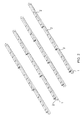
- Fig. 1 shows four parallel arranged square beam 1 of a mounting system according to the invention, wherein the square beam 1 can be mounted on any surface, for example on a roof structure.
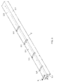
- the mounting rails are U-shaped in cross-section, as in particular Fig. 3 clarified, and overlap with their lateral legs 2.1 and 2.2 after placing the lateral edges of the square beam.
- FIG. 3 Further clarified Fig. 3 in that the mounting rails 2 have at one of their ends a transverse web 2.3, which ensures that the mounting rail, after placement on the square beam 1, is inclined to the surface of the square beam 1, such as Fig. 2 clarified. As a result, an overlapping arrangement of adjacent mounting rails at the junction of two rails 2 is possible.
- the mounting rails also have an upwardly projecting stop 8 for later alseuticde and from the Fig. 7 and 8th apparent plate-shaped elements 7.
- the stops 8 also serve to attach the plate-shaped elements 7.
- the mounting rails are provided at its base 2.4 with transverse groove-shaped slots 2.5.
- the length of the bathleitbleche 3 corresponds to the mutual distance of the square beam 1. However, it could also be 3 blanketleitbleche be provided, whose length spans 2 or 3 spaces between the square beams 1.
- Fig. 5 illustrates, have the sauceleitbleche a central, longitudinal recess 3.1, which have a U-shaped cross-section corresponding to the cross section of the transverse slots 2.5 of the mounting rails 2.
- the heat conducting plates 3 are anchored in the transverse slots 2.5.
- the height h of the recesses 3.1 corresponds to a multiple of the diameter of the U-shaped recesses 3.1.
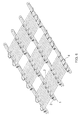
- tubes 4 After inserting the heat conducting plates 3 in the mounting rails 2 3 tubes 4 are laid for a cooling and / or heating fluid in the wells 3.1 of the heat conducting.
- the heat conducting 3 serve in the operation of the heating or cooling system to heat of plate-shaped elements 7, according to Fig. 7 be placed on the heat conducting plates 3 after inserting the tubes 4 in the heat conducting plates 3, to conduct to the tubes 4 and thus to heat the circulating in the tubes liquid.
- the plate-shaped elements 7 are thereby cooled.
- the plate-shaped elements 7, however, can also be heated. In this case, the heat is conducted from a heating fluid in the tubes 4 and the heat conducting plates to the plate-shaped elements 7.
- the plate-shaped elements 7, for example, snow and ice can be kept free.
- Fig. 7 also illustrates, 7 horizontal seals 5 and vertical seals 6 are arranged between the plate-shaped elements, so that the plate-shaped elements 7 can form a total waterproof roof surface or building facade.
- the plate-shaped elements 7 may preferably be photovoltaic modules. In this way, the solar radiation can be used both for power generation as well as for heating a building.
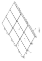
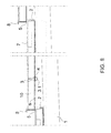
- Fig. 8 From the side view in Fig. 8 is the overlapping arrangement of the mounting rails 2 and thus also the plate-shaped elements 7 can be seen. It can also be seen that due to the height of the depressions 3.1 a free space 10 between the mounting rails 2 and the plate-shaped elements 7 is formed. About this space 10, the plate-shaped elements 7 are ventilated behind, which is particularly advantageous when using photovoltaic modules as a plate-shaped element 7. Not only by the heat dissipation by means of the Winnipegleitbleche 3, but also by the rear ventilation, the operating temperature of the photovoltaic modules can be kept in an optimal range.
Landscapes
- Engineering & Computer Science (AREA)
- Physics & Mathematics (AREA)
- General Engineering & Computer Science (AREA)
- Mechanical Engineering (AREA)
- Thermal Sciences (AREA)
- Chemical & Material Sciences (AREA)
- Combustion & Propulsion (AREA)
- Life Sciences & Earth Sciences (AREA)
- Sustainable Development (AREA)
- Sustainable Energy (AREA)
- Geometry (AREA)
- Roof Covering Using Slabs Or Stiff Sheets (AREA)
- Photovoltaic Devices (AREA)
Abstract
Ein Montagesystem für ein durch plattenförmige Elemente (7) abgedecktes Flächenheiz- oder Kühlsystem (4) mit mehreren, parallel zueinander auf einem Untergrund befestigbaren Vierkant-Trägern (1), auf die U-förmige Montageschienen (2) aufsetzbar sind, wobei die Montageschienen (2) an ihrer Basis (2.4) mit Querschlitzen (2.5) versehen sind, in die mit einer U-förmigen Vertiefung (3.1) versehene Wärmeleitbleche (3) mit ihren Vertiefungen (3.1) einlegbar sind und in den Vertiefungen Rohre (4) für eine Heiz- und/oder Kühlflüssigkeit einlegbar sind, bevor die plattenförmigen Elemente (7) aufsetzbar und an den Montageschienen (2) befestigbar sind.A mounting system for a surface heating or cooling system (4) covered by plate-shaped elements (7) with a plurality of square supports (1) which can be fastened parallel to one another on a substrate, to which U-shaped mounting rails (2) can be placed, wherein the mounting rails ( 2) are provided at their base (2.4) with transverse slots (2.5), in the provided with a U-shaped recess (3.1) Wärmeleitbleche (3) with their recesses (3.1) can be inserted and in the wells tubes (4) for a Heating and / or cooling liquid can be inserted before the plate-shaped elements (7) can be placed and fastened to the mounting rails (2).
Description
Im Zuge der Förderung der Nutzung erneuerbarer Energien wird zunehmend die Infrarotstrahlung der Sonne zum Heizen von Gebäuden genutzt. Dazu können an den Dächern und/oder Fassaden von Gebäuden oder auch an vom Gebäude unabhängigen Anlagen Sonnenkollektoren eingesetzt werden. Diese Kollektoren können als Flachkollektoren oder Röhrenkollektoren ausgeführt sein. Werden diese Kollektoren an Gebäudefassaden eingesetzt, so ist es wünschenswert, diese aus optischen Gründen nach außen durch plattenförmige Elemente abzudecken. Diese plattenförmigen Elemente können auch Photovoltaikmodule sein, sodass die Sonneneinstrahlung gleichzeitig zur Stromerzeugung genutzt werden kann.In the course of promoting the use of renewable energies, the infrared radiation of the sun is increasingly being used to heat buildings. These can be used on the roofs and / or facades of buildings or on buildings independent solar panels. These collectors can be designed as flat collectors or tube collectors. If these collectors are used on building facades, it is desirable to cover them for optical reasons to the outside through plate-shaped elements. These plate-shaped elements can also be photovoltaic modules, so that the solar radiation can be used simultaneously to generate electricity.
Weiter sind Flächenheizsysteme als Fußboden- oder Wandheizungen bekannt, die ebenfalls teilweise durch plattenförmige Elemente, beispielsweise durch Fliesen, nach außen abgedeckt sind. Bisher gibt es jedoch kein einfaches Montagesystem, dass das Anbringen eines Flächenheiz- oder Kühlsystems sowie darüber oder davor angeordneter plattenförmiger Elemente in standardisierter Weise an einem beliebigen Untergrund ermöglicht. Der vorliegenden Erfindung liegt daher die Aufgabe zugrunde, ein derartiges Montagesystem zur Verfügung zu stellen.Next area heating systems are known as floor or wall heaters, which are also partially covered by plate-shaped elements, for example by tiles to the outside. So far, however, there is no simple mounting system that allows the attachment of a Flächenheiz- or cooling system and arranged above or plate-shaped elements in a standardized manner on any surface. The present invention is therefore based on the object to provide such a mounting system.
Die Aufgabe wird gelöst durch ein Montagesystem für ein durch plattenförmige Elemente abgedecktes Flächenheiz- oder Kühlsystem mit mehreren parallel zueinander auf einem Untergrund befestigbaren Vierkant-Trägern, auf die U-förmige Montageschienen aufsetzbar sind, wobei die Montageschienen an ihrer Basis mit Querschlitzen versehen sind, in die mit einer U-förmigen Vertiefung versehene Wärmleitbleche mit ihren Vertiefungen einlegbar sind und in den Vertiefungen Rohre eines Heiz- und/oder Kühlsystems einlegbar sind, bevor die plattenförmigen Elemente aufsetzbar und an den Montageschienen befestigbar sind.The object is achieved by a mounting system for a covered by plate-shaped elements Flächenheiz- or cooling system with a plurality of mutually parallel fastened to a substrate square beams on the U-shaped mounting rails are placed, the mounting rails are provided at their base with transverse slots, in which are provided with a U-shaped recess Wärmleitbleche with their recesses and in the wells tubes of a heating and / or cooling system can be inserted before the plate-shaped elements can be placed and fastened to the mounting rails.
Bei dem erfindungsgemäßen Montagesystem können die Vierkant-Träger auf einen beliebigen Untergrund, beispielsweise auf einer Dachkonstruktion befestigt werden. Der gegenseitige Abstand kann den Abmessungen der verwendeten plattenförmigen Elemente angepasst werden. Die Rohre für die Kühl- oder Heizflüssigkeit eines Kühl- oder Heizsystems lassen sich über mehrere Vierkant-Träger quer zu deren Längsrichtung hinweg führen, wodurch die gegenseitige Verbindung einzelner Kollektoren untereinander, wie dies bei marktüblichen Sonnenkollektoren der Fall ist, hier entfallen kann. Außerdem sorgen die Vierkant-Träger dafür, dass das Heizsystem und die plattenförmigen Elemente durch den Zwischenraum zwischen dem Untergrund und den Wärmeleitflächen hinterlüftet werden kann.In the mounting system according to the invention, the square beam can be mounted on any surface, for example on a roof construction. The mutual distance can be adapted to the dimensions of the plate-shaped elements used. The tubes for the cooling or heating fluid of a cooling or heating system can be across several square carrier transverse to their longitudinal direction away, whereby the mutual connection of individual collectors with each other, as is the case with commercially available solar panels, can be omitted here. In addition, the square support ensure that the heating system and the plate-shaped elements can be ventilated through the space between the substrate and the heat conduction surfaces.
Nach der Montage der Vierkant-Träger werden die Montageschienen auf die Vierkant-Träger aufgesetzt, wobei die Schenkel der Montageschienen die Vierkant-Träger seitlich übergreifen. Die Querschlitze in der Basis der Montageschienen können dem Rohrdurchmesser für die Heiz- und/oder Kühlflüssigkeit angepasst werden. Auch der gegenseitige Abstand der Querschlitze lässt sich einfach an die jeweiligen Erfordernisse anpassen. Die Wärmeleitbleche dienen der optimalen Wärmeübertragung zwischen den Rohren und den plattenförmigen Elementen. Mit ihrer Hilfe kann den plattenförmigen Elementen entweder Wärme zugeführt oder aber Wärme von diesen abgeführt werden.After mounting the square beam, the mounting rails are placed on the square beam, the legs of the mounting rails laterally overlap the square beam. The transverse slots in the base of the mounting rails can be adapted to the pipe diameter for the heating and / or cooling liquid. The mutual distance of the transverse slots can also be easily adapted to the respective requirements. The Wärmeleitbleche serve optimal heat transfer between the tubes and the plate-shaped elements. With their help, the plate-shaped elements either heat supplied or heat can be removed from them.
Die plattenförmigen Elemente können vorzugsweise Photovoltaikmodule sein. Mit diesen Modulen kann ein Teil des Spektrums des Sonnenlichts zur Stromerzeugung genutzt werden. Neben der Stromerzeugung durch die Photovoltaikmodule wird auch die durch die Sonne erzeugte Wärme genutzt. Die Wärme wird über die Leitbleche von den Photovoltaikmodulen ab- und der in den Rohren zirkulierenden Flüssigkeit zugeführt. Die Abführung der Wärme von den Photovoltaikmodulen hat zudem den Vorteil, dass deren Betriebstemperatur in einem optimalen Bereich gehalten werden kann. Im Winter können die Photovoltaikmodule dagegen beheizt werden, indem heiße Flüssigkeit durch die Rohre geleitet wird. Auf diese Weise lassen sich die Photovoltaikmodule Schnee- und Eisfrei halten. Als plattenförmige Elemente lassen sich jedoch nicht nur Photovoltaikmodule, sondern auch andere Fassaden- oder Dachplatten einsetzen.The plate-shaped elements may preferably be photovoltaic modules. With these modules, part of the spectrum of sunlight can be used to generate electricity. In addition to the power generated by the photovoltaic modules, the heat generated by the sun is also used. The heat is dissipated via the baffles from the photovoltaic modules and fed to the liquid circulating in the tubes. The dissipation of heat from the photovoltaic modules also has the advantage that their operating temperature can be kept in an optimal range. In winter, however, the photovoltaic modules can be heated by passing hot liquid through the pipes. In this way, the photovoltaic modules can be kept free of snow and ice. As a plate-shaped elements, however, not only photovoltaic modules, but also other facade or roof panels can be used.
Weitere Vorteile ergeben sich, wenn die Montageschienen in Längsrichtung geneigt auf die Vierkant-Träger aufsetzbar sind. Auf diese Weise erhalten auch die plattenförmigen Elemente eine Neigung, was das Ablaufen von Regenwasser erleichtert. Werden mehrere Einzelschienen hintereinander auf die Vierkant-Träger aufgesetzt, wobei jede Montageschiene eine der Höhe eines plattenförmiges Elements entsprechende Länge aufweist, so können die einzelnen Platten auch in unterschiedlicher Neigung und in unterschiedlichen gegenseitigem Abstand angeordnet werden. Insbesondere können mehrere, in Längsrichtung geneigten Montageschienen hintereinander auf die Vierkant-Träger aufgesetzt werden, wobei sich benachbarte Montageschienen an der Stoßstelle überlappen, wodurch eine schuppenartige Anordnung mehrerer plattenförmiger Elemente in Längsrichtung der Vierkant-Träger möglich ist, was insbesondere bei der Montage des Flächenheiz- und Kühlsystems auf einer Dachfläche von Vorteil ist. An den Überlappungsstellen können Dichtigkeitsprobleme zuverlässig vermieden werden, wenn die plattenförmigen Elemente dachziegelartig überlappend montiert werden. Dabei ist es weiter von Vorteil, wenn die Montageschienen an ihrem gegenüber der Oberfläche der Vierkant-Träger höher liegenden Ende mit einem Anschlag für eine Kante eines plattenförmigen Elements versehen sind, an dem das plattenförmige Element auch befestigbar ist. Der Anschlag hält das plattenförmige Element in Position und dient gleichzeitig seiner Befestigung. Die Montage der plattenförmigen Elemente lässt sich dadurch weiter vereinfachen.Further advantages arise when the mounting rails are inclined in the longitudinal direction on the square beam can be placed. In this way, the plate-shaped elements get a slope, which facilitates the drainage of rainwater. Be several single rails in a row placed on the square beam, each mounting rail having a height of a plate-shaped element corresponding length, the individual plates can also be arranged in different inclination and at different mutual distance. In particular, a plurality of longitudinally inclined mounting rails can be placed one behind the other on the square beam, with adjacent mounting rails overlapping at the joint, whereby a scale-like arrangement of a plurality of plate-shaped elements in the longitudinal direction of the square beam is possible, which in particular during assembly of Flächenheiz- and cooling system on a roof surface is beneficial. Leakage problems can be reliably avoided at the overlapping points if the plate-shaped elements are mounted like a roof tile overlapping. It is further advantageous if the mounting rails are provided at its opposite the surface of the square beam higher end with a stop for an edge of a plate-shaped element on which the plate-shaped element is also fastened. The stop holds the plate-shaped element in position and serves at the same time its attachment. The assembly of the plate-shaped elements can be further simplified.
Bei einer bevorzugten Ausführungsform weisen die Querschlitze der Montageschienen einen dem Querschnitt der Vertiefungen der Wärmeleitbleche angepassten U-förmigen Querschnitt auf. Dadurch werden die Wärmeleitbleche sowie die darin verlegten Rohre sicher in den Querschlitzen gehalten.In a preferred embodiment, the transverse slots of the mounting rails have a U-shaped cross section adapted to the cross section of the recesses of the heat conducting plates. As a result, the Wärmeleitbleche and laid therein pipes are securely held in the transverse slots.
Bei einer weiteren bevorzugten Ausführungsform entspricht die Tiefe der Vertiefungen der Wärmeleitbleche einem Vielfachen des Durchmessers der in den Vertiefungen verlegbaren Rohre. Dadurch entsteht ein Abstand zwischen den Auflageflächen der Wärmleitbleche und den Montageschienen und gleichzeitig ein Abstand zwischen den auf die Wärmeleitbleche aufgelegten plattenförmigen Elementen und den Montageschienen. Durch diese Maßnahme wird der Hinterlüftungsraum zwischen dem Untergrund und den plattenförmigen Elementen weiter vergrößert.In a further preferred embodiment, the depth of the recesses of the heat conducting plates corresponds to a multiple of the diameter of the pipes which can be laid in the recesses. This creates a gap between the bearing surfaces of the heat baffles and the mounting rails and at the same time a distance between the placed on the heat conducting plates plate-shaped elements and the mounting rails. By this measure, the rear ventilation space between the substrate and the plate-shaped elements is further increased.
Bei einer bevorzugten Ausgestaltung des Montagesystems sind die Vierkant-Träger Vierkanthölzer, die preiswert und einfach zu montieren sind. Sie können an einer Fassade oder einer Dachkonstruktion eines Gebäudes befestigbar sein. Aber auch eine Montage an einer separaten Einrichtung ist möglich.In a preferred embodiment of the mounting system, the square beam square, which are inexpensive and easy to assemble. They can be fastened to a facade or roof construction of a building. But also a mounting on a separate device is possible.
Nachfolgend wird ein bevorzugtes Ausführungsbeispiel eines erfindungsgemäßen Montagesystems anhand der Zeichnung näher beschrieben.Hereinafter, a preferred embodiment of a mounting system according to the invention is described in detail with reference to the drawing.
Es zeigen:
- Fig. 1
- eine perspektivische Ansicht auf parallel angeordnete Vierkant-Träger eines erfindungsgemäßen Montagesystems;
- Fig. 2
- eine perspektivische Ansicht der Vierkant-Träger aus
Fig. 1 mit aufgesetzten Montageschienen; - Fig. 3
- eine perspektivische Einzeldarstellung einer Montageschiene aus
Fig. 2 ; - Fig. 4
- eine perspektivische Ansicht der Vierkant-Träger und Montageschienen aus
Fig. 2 mit eingesetzten Wärmeleitblechen; - Fig. 5
- eine perspektivische Einzeldarstellung eines Wärmeleitblechs aus
Fig. 4 ; - Fig. 6
- eine perspektivische Ansicht der Vierkant-Träger, Montageschienen und Wärmeleitbleche aus
Fig. 4 mit eingelegten Rohren für eine Kühl- und/oder Heizflüssigkeit; - Fig. 7
- eine perspektivische Ansicht des Montagesystems aus
Fig. 6 mit aufgesetzten plattenförmigen Elementen; - Fig. 8
- eine Seitenansicht der Anordnung aus
Fig. 7 ohne Rohre.
- Fig. 1
- a perspective view of parallel arranged square beam of a mounting system according to the invention;
- Fig. 2
- a perspective view of the square carrier
Fig. 1 with attached mounting rails; - Fig. 3
- an individual perspective view of a mounting rail
Fig. 2 ; - Fig. 4
- a perspective view of the square beam and mounting rails
Fig. 2 with inserted Wärmeleitblechen; - Fig. 5
- a perspective individual representation of a Wärmeleitblechs
Fig. 4 ; - Fig. 6
- a perspective view of the square beam, mounting rails and Wärmeleitbleche
Fig. 4 with inserted tubes for a cooling and / or heating fluid; - Fig. 7
- a perspective view of the mounting system
Fig. 6 with attached plate-shaped elements; - Fig. 8
- a side view of the arrangement
Fig. 7 without tubes.
Nach dem Verlegen der Vierkant-Träger 1 werden auf diese mehrere Montageschienen in Längsrichtung der Vierkant-Träger hintereinander auf die Vierkant-Träger 1 aufgesetzt. Die Montageschienen sind dabei im Querschnitt U-förmig, wie insbesondere auch
Weiter verdeutlicht
An demjenigen Ende, an dem der Steg 2.3 angeordnet ist, weisen die Montageschienen außerdem einen nach oben abstehenden Anschlag 8 für später aufzusetzende und aus den
In diese Querschlitze 2.5 lassen sich aus den
Wie
Nach dem Einsetzen der Wärmeleitbleche 3 in die Montageschienen 2 werden in den Vertiefungen 3.1 der Wärmeleitbleche 3 Rohre 4 für eine Kühl- und/oder Heizflüssigkeit verlegt. Die Wärmeleitbleche 3 dienen im Betrieb des Heiz- oder Kühlsystems dazu, Wärme von plattenförmigen Elementen 7, die gemäß
Wie
Aus der Seitenansicht in
Claims (10)
dadurch gekennzeichnet, dass die Montageschienen (2) in Längsrichtung geneigt auf die Vierkant-Träger (1) aufsetzbar sind.Mounting system according to one of the preceding claims,
characterized in that the mounting rails (2) in the longitudinal direction inclined to the square beam (1) can be placed.
dadurch gekennzeichnet, dass die Querschlitze (2.5) der Montageschienen (2) einen U-förmigen Querschnitt aufweisen.Mounting system according to one of the preceding claims,
characterized in that the transverse slots (2.5) of the mounting rails (2) have a U-shaped cross section.
dadurch gekennzeichnet, dass die Tiefe (h) der Vertiefungen (3.1) der Wärmeleitbleche (3) einem Vielfachen des Durchmessers der in den Vertiefungen (3.1) verlegbaren Rohre (4) entspricht.Mounting system according to one of the preceding claims,
characterized in that the depth (h) of the recesses (3.1) of the Wärmeleitbleche (3) corresponds to a multiple of the diameter of the in the recesses (3.1) laid pipes (4).
dadurch gekennzeichnet, dass die Vierkant-Träger (1) Vierkanthölzer sind.Mounting system according to one of the preceding claims,
characterized in that the square beam (1) are square timber.
Applications Claiming Priority (1)
| Application Number | Priority Date | Filing Date | Title |
|---|---|---|---|
| DE102014105384.2A DE102014105384B4 (en) | 2014-04-15 | 2014-04-15 | Mounting system for a surface heating or cooling system covered by plate-shaped elements |
Publications (2)
| Publication Number | Publication Date |
|---|---|
| EP2937646A1 true EP2937646A1 (en) | 2015-10-28 |
| EP2937646B1 EP2937646B1 (en) | 2018-07-25 |
Family
ID=52997840
Family Applications (1)
| Application Number | Title | Priority Date | Filing Date |
|---|---|---|---|
| EP15162580.3A Active EP2937646B1 (en) | 2014-04-15 | 2015-04-07 | Mounting system for an area heating or cooling system covered by plate-shaped elements |
Country Status (2)
| Country | Link |
|---|---|
| EP (1) | EP2937646B1 (en) |
| DE (1) | DE102014105384B4 (en) |
Cited By (3)
| Publication number | Priority date | Publication date | Assignee | Title |
|---|---|---|---|---|
| EP3190699A1 (en) * | 2016-01-07 | 2017-07-12 | Mathias Beyersdorffer | Hybrid solar module roof mounting system |
| EP3715745A1 (en) * | 2019-03-27 | 2020-09-30 | Mathias Beyersdorffer | Hybrid solar module system and method of use, fastening system for a hybrid solar module system |
| EP4163452A1 (en) * | 2021-10-11 | 2023-04-12 | Julius Fritsche GmbH | Pitched roof construction |
Citations (6)
| Publication number | Priority date | Publication date | Assignee | Title |
|---|---|---|---|---|
| DE10125773A1 (en) * | 2000-05-30 | 2001-12-06 | Kurt Schade Gmbh & Co Ing | Set of structural members for installing photovoltaic solar modules or water-carrying thermo-modules on inclined roof includes support section, holder and covering members |
| DE102011106083A1 (en) * | 2011-06-08 | 2012-12-13 | Schletter Gmbh | Stand for PV modules |
| DE102011088153B3 (en) * | 2011-12-09 | 2013-01-03 | Krinner Innovation Gmbh | Mounting system for photovoltaic module, particularly thin film module, has two parallel longitudinal beams inclined in row against horizontal, where longitudinal beams are spaced from each other and placed at base frame |
| DE202012004333U1 (en) * | 2012-02-13 | 2013-02-01 | Werner Ilzhöfer | Device for supporting at least one solar module |
| EP2573486A2 (en) * | 2011-09-20 | 2013-03-27 | REHAU AG + Co | Clamp element for a fixing system for panel-shaped elements, fixing system comprising such a clamp element and use of same |
| JP2013147831A (en) * | 2012-01-18 | 2013-08-01 | Sharp Corp | Solar cell module, support structure of solar cell module, installation method of solar cell module, and photovoltaic power generation system |
Family Cites Families (3)
| Publication number | Priority date | Publication date | Assignee | Title |
|---|---|---|---|---|
| DE19902650A1 (en) * | 1999-01-24 | 2000-07-27 | Mueller Gerald Patrick | Process for the recovery of solar energy comprises using a thin layer solar cell and removing thermal energy using an air heat exchanger or a water heat exchanger below the cell |
| DE10233715A1 (en) * | 2001-07-24 | 2003-02-20 | Bernhard Beck | Heat exchanger for heating buildings etc. is based on the use of the latent heat of solidification and as such can be used in cold climates by extracting heat from ambient air outside a building |
| DE102009005540B3 (en) * | 2009-01-20 | 2010-08-05 | TechConcept GbR (vertretungsberechtigte Gesellschafter: Hans-Ulrich Karsch, 96271 Grub und Harry Steinhäuser, 96191 Viereth-Trunstadt) | A ground collector device and mounting device and method of making a ground collector device |
-
2014
- 2014-04-15 DE DE102014105384.2A patent/DE102014105384B4/en not_active Expired - Fee Related
-
2015
- 2015-04-07 EP EP15162580.3A patent/EP2937646B1/en active Active
Patent Citations (6)
| Publication number | Priority date | Publication date | Assignee | Title |
|---|---|---|---|---|
| DE10125773A1 (en) * | 2000-05-30 | 2001-12-06 | Kurt Schade Gmbh & Co Ing | Set of structural members for installing photovoltaic solar modules or water-carrying thermo-modules on inclined roof includes support section, holder and covering members |
| DE102011106083A1 (en) * | 2011-06-08 | 2012-12-13 | Schletter Gmbh | Stand for PV modules |
| EP2573486A2 (en) * | 2011-09-20 | 2013-03-27 | REHAU AG + Co | Clamp element for a fixing system for panel-shaped elements, fixing system comprising such a clamp element and use of same |
| DE102011088153B3 (en) * | 2011-12-09 | 2013-01-03 | Krinner Innovation Gmbh | Mounting system for photovoltaic module, particularly thin film module, has two parallel longitudinal beams inclined in row against horizontal, where longitudinal beams are spaced from each other and placed at base frame |
| JP2013147831A (en) * | 2012-01-18 | 2013-08-01 | Sharp Corp | Solar cell module, support structure of solar cell module, installation method of solar cell module, and photovoltaic power generation system |
| DE202012004333U1 (en) * | 2012-02-13 | 2013-02-01 | Werner Ilzhöfer | Device for supporting at least one solar module |
Cited By (3)
| Publication number | Priority date | Publication date | Assignee | Title |
|---|---|---|---|---|
| EP3190699A1 (en) * | 2016-01-07 | 2017-07-12 | Mathias Beyersdorffer | Hybrid solar module roof mounting system |
| EP3715745A1 (en) * | 2019-03-27 | 2020-09-30 | Mathias Beyersdorffer | Hybrid solar module system and method of use, fastening system for a hybrid solar module system |
| EP4163452A1 (en) * | 2021-10-11 | 2023-04-12 | Julius Fritsche GmbH | Pitched roof construction |
Also Published As
| Publication number | Publication date |
|---|---|
| EP2937646B1 (en) | 2018-07-25 |
| DE102014105384A1 (en) | 2015-10-15 |
| DE102014105384B4 (en) | 2016-01-14 |
Similar Documents
| Publication | Publication Date | Title |
|---|---|---|
| EP2619382B1 (en) | Fastening system for facade elements, profiled insert rail therefor and assembly method | |
| DE102015119849A1 (en) | Photovoltaic system, module holder system and reflector | |
| DE102005028830A1 (en) | Roofing and method therefor | |
| DE202008013414U1 (en) | Holder for solar modules for installation on a footprint | |
| EP2937646B1 (en) | Mounting system for an area heating or cooling system covered by plate-shaped elements | |
| EP2187448A2 (en) | System for attaching, solar assembly and method for filling a solar assembly | |
| DE102006006718B4 (en) | solar collector | |
| WO2004017424A2 (en) | Fixing device for photovoltaic modules | |
| DE10142383C2 (en) | Carrier for solar modules and their use as well as roof covering or facade | |
| EP2987185A1 (en) | Façade element or roof element | |
| EP2213961A2 (en) | Device for elevating solar modules | |
| DE202009014816U1 (en) | Mounting system for the elevation of solar modules | |
| DE102009051756A1 (en) | Mounting system for supporting solar modules on flat roof, has base plates connected with transverse beams such that base plates adjust flexibly surface irregularities by force-fit connection of end zones of each base plate section | |
| DE102010041161B4 (en) | Solar module mounting device | |
| DE202016100046U1 (en) | Hybrid solar panel roof mounting system | |
| DE10136037A1 (en) | Roof integrated solar module system has distance between plating arrangement and modules for ventilating the rear of modules and carrying away water | |
| DE102011121135B4 (en) | Solar energy system | |
| AT507570B1 (en) | RAILING | |
| WO2018153543A1 (en) | Connection system for intersecting profiles having adjustable connection elements, solar plant, open area plant, roof, carport having the lift-up sliding technology system | |
| DE102007039469B4 (en) | System plate for laying plastic pipes of the heating or cooling circuits of surface heating and cooling installations | |
| EP1818625B1 (en) | Solar collector assembly | |
| DE2925293C3 (en) | Roofing | |
| DE202012010492U1 (en) | thermal insulation board | |
| DE102010014273A1 (en) | Fixing system with flat plate-shaped components, in particular photovoltaic or solar thermal elements | |
| DE9114848U1 (en) | Substructure mounting system |
Legal Events
| Date | Code | Title | Description |
|---|---|---|---|
| PUAI | Public reference made under article 153(3) epc to a published international application that has entered the european phase |
Free format text: ORIGINAL CODE: 0009012 |
|
| AK | Designated contracting states |
Kind code of ref document: A1 Designated state(s): AL AT BE BG CH CY CZ DE DK EE ES FI FR GB GR HR HU IE IS IT LI LT LU LV MC MK MT NL NO PL PT RO RS SE SI SK SM TR |
|
| AX | Request for extension of the european patent |
Extension state: BA ME |
|
| 17P | Request for examination filed |
Effective date: 20160406 |
|
| RBV | Designated contracting states (corrected) |
Designated state(s): AL AT BE BG CH CY CZ DE DK EE ES FI FR GB GR HR HU IE IS IT LI LT LU LV MC MK MT NL NO PL PT RO RS SE SI SK SM TR |
|
| STAA | Information on the status of an ep patent application or granted ep patent |
Free format text: STATUS: EXAMINATION IS IN PROGRESS |
|
| 17Q | First examination report despatched |
Effective date: 20170123 |
|
| GRAP | Despatch of communication of intention to grant a patent |
Free format text: ORIGINAL CODE: EPIDOSNIGR1 |
|
| STAA | Information on the status of an ep patent application or granted ep patent |
Free format text: STATUS: GRANT OF PATENT IS INTENDED |
|
| INTG | Intention to grant announced |
Effective date: 20171206 |
|
| GRAS | Grant fee paid |
Free format text: ORIGINAL CODE: EPIDOSNIGR3 |
|
| GRAA | (expected) grant |
Free format text: ORIGINAL CODE: 0009210 |
|
| STAA | Information on the status of an ep patent application or granted ep patent |
Free format text: STATUS: THE PATENT HAS BEEN GRANTED |
|
| AK | Designated contracting states |
Kind code of ref document: B1 Designated state(s): AL AT BE BG CH CY CZ DE DK EE ES FI FR GB GR HR HU IE IS IT LI LT LU LV MC MK MT NL NO PL PT RO RS SE SI SK SM TR |
|
| REG | Reference to a national code |
Ref country code: GB Ref legal event code: FG4D Free format text: NOT ENGLISH |
|
| REG | Reference to a national code |
Ref country code: CH Ref legal event code: EP |
|
| REG | Reference to a national code |
Ref country code: AT Ref legal event code: REF Ref document number: 1022193 Country of ref document: AT Kind code of ref document: T Effective date: 20180815 |
|
| REG | Reference to a national code |
Ref country code: IE Ref legal event code: FG4D Free format text: LANGUAGE OF EP DOCUMENT: GERMAN |
|
| REG | Reference to a national code |
Ref country code: DE Ref legal event code: R096 Ref document number: 502015005194 Country of ref document: DE |
|
| REG | Reference to a national code |
Ref country code: CH Ref legal event code: NV Representative=s name: ROTTMANN, ZIMMERMANN + PARTNER AG, CH |
|
| REG | Reference to a national code |
Ref country code: NL Ref legal event code: MP Effective date: 20180725 |
|
| REG | Reference to a national code |
Ref country code: LT Ref legal event code: MG4D |
|
| PG25 | Lapsed in a contracting state [announced via postgrant information from national office to epo] |
Ref country code: NL Free format text: LAPSE BECAUSE OF FAILURE TO SUBMIT A TRANSLATION OF THE DESCRIPTION OR TO PAY THE FEE WITHIN THE PRESCRIBED TIME-LIMIT Effective date: 20180725 |
|
| PG25 | Lapsed in a contracting state [announced via postgrant information from national office to epo] |
Ref country code: FI Free format text: LAPSE BECAUSE OF FAILURE TO SUBMIT A TRANSLATION OF THE DESCRIPTION OR TO PAY THE FEE WITHIN THE PRESCRIBED TIME-LIMIT Effective date: 20180725 Ref country code: PL Free format text: LAPSE BECAUSE OF FAILURE TO SUBMIT A TRANSLATION OF THE DESCRIPTION OR TO PAY THE FEE WITHIN THE PRESCRIBED TIME-LIMIT Effective date: 20180725 Ref country code: LT Free format text: LAPSE BECAUSE OF FAILURE TO SUBMIT A TRANSLATION OF THE DESCRIPTION OR TO PAY THE FEE WITHIN THE PRESCRIBED TIME-LIMIT Effective date: 20180725 Ref country code: BG Free format text: LAPSE BECAUSE OF FAILURE TO SUBMIT A TRANSLATION OF THE DESCRIPTION OR TO PAY THE FEE WITHIN THE PRESCRIBED TIME-LIMIT Effective date: 20181025 Ref country code: NO Free format text: LAPSE BECAUSE OF FAILURE TO SUBMIT A TRANSLATION OF THE DESCRIPTION OR TO PAY THE FEE WITHIN THE PRESCRIBED TIME-LIMIT Effective date: 20181025 Ref country code: GR Free format text: LAPSE BECAUSE OF FAILURE TO SUBMIT A TRANSLATION OF THE DESCRIPTION OR TO PAY THE FEE WITHIN THE PRESCRIBED TIME-LIMIT Effective date: 20181026 Ref country code: RS Free format text: LAPSE BECAUSE OF FAILURE TO SUBMIT A TRANSLATION OF THE DESCRIPTION OR TO PAY THE FEE WITHIN THE PRESCRIBED TIME-LIMIT Effective date: 20180725 Ref country code: IS Free format text: LAPSE BECAUSE OF FAILURE TO SUBMIT A TRANSLATION OF THE DESCRIPTION OR TO PAY THE FEE WITHIN THE PRESCRIBED TIME-LIMIT Effective date: 20181125 Ref country code: SE Free format text: LAPSE BECAUSE OF FAILURE TO SUBMIT A TRANSLATION OF THE DESCRIPTION OR TO PAY THE FEE WITHIN THE PRESCRIBED TIME-LIMIT Effective date: 20180725 |
|
| REG | Reference to a national code |
Ref country code: CH Ref legal event code: PK Free format text: BERICHTIGUNGEN |
|
| RIC2 | Information provided on ipc code assigned after grant |
Ipc: F24J 2/52 20060101AFI20150923BHEP |
|
| PG25 | Lapsed in a contracting state [announced via postgrant information from national office to epo] |
Ref country code: AL Free format text: LAPSE BECAUSE OF FAILURE TO SUBMIT A TRANSLATION OF THE DESCRIPTION OR TO PAY THE FEE WITHIN THE PRESCRIBED TIME-LIMIT Effective date: 20180725 Ref country code: HR Free format text: LAPSE BECAUSE OF FAILURE TO SUBMIT A TRANSLATION OF THE DESCRIPTION OR TO PAY THE FEE WITHIN THE PRESCRIBED TIME-LIMIT Effective date: 20180725 Ref country code: LV Free format text: LAPSE BECAUSE OF FAILURE TO SUBMIT A TRANSLATION OF THE DESCRIPTION OR TO PAY THE FEE WITHIN THE PRESCRIBED TIME-LIMIT Effective date: 20180725 |
|
| REG | Reference to a national code |
Ref country code: DE Ref legal event code: R097 Ref document number: 502015005194 Country of ref document: DE |
|
| PG25 | Lapsed in a contracting state [announced via postgrant information from national office to epo] |
Ref country code: IT Free format text: LAPSE BECAUSE OF FAILURE TO SUBMIT A TRANSLATION OF THE DESCRIPTION OR TO PAY THE FEE WITHIN THE PRESCRIBED TIME-LIMIT Effective date: 20180725 Ref country code: EE Free format text: LAPSE BECAUSE OF FAILURE TO SUBMIT A TRANSLATION OF THE DESCRIPTION OR TO PAY THE FEE WITHIN THE PRESCRIBED TIME-LIMIT Effective date: 20180725 Ref country code: RO Free format text: LAPSE BECAUSE OF FAILURE TO SUBMIT A TRANSLATION OF THE DESCRIPTION OR TO PAY THE FEE WITHIN THE PRESCRIBED TIME-LIMIT Effective date: 20180725 Ref country code: ES Free format text: LAPSE BECAUSE OF FAILURE TO SUBMIT A TRANSLATION OF THE DESCRIPTION OR TO PAY THE FEE WITHIN THE PRESCRIBED TIME-LIMIT Effective date: 20180725 Ref country code: CZ Free format text: LAPSE BECAUSE OF FAILURE TO SUBMIT A TRANSLATION OF THE DESCRIPTION OR TO PAY THE FEE WITHIN THE PRESCRIBED TIME-LIMIT Effective date: 20180725 |
|
| PG25 | Lapsed in a contracting state [announced via postgrant information from national office to epo] |
Ref country code: DK Free format text: LAPSE BECAUSE OF FAILURE TO SUBMIT A TRANSLATION OF THE DESCRIPTION OR TO PAY THE FEE WITHIN THE PRESCRIBED TIME-LIMIT Effective date: 20180725 Ref country code: SK Free format text: LAPSE BECAUSE OF FAILURE TO SUBMIT A TRANSLATION OF THE DESCRIPTION OR TO PAY THE FEE WITHIN THE PRESCRIBED TIME-LIMIT Effective date: 20180725 Ref country code: SM Free format text: LAPSE BECAUSE OF FAILURE TO SUBMIT A TRANSLATION OF THE DESCRIPTION OR TO PAY THE FEE WITHIN THE PRESCRIBED TIME-LIMIT Effective date: 20180725 |
|
| PLBE | No opposition filed within time limit |
Free format text: ORIGINAL CODE: 0009261 |
|
| STAA | Information on the status of an ep patent application or granted ep patent |
Free format text: STATUS: NO OPPOSITION FILED WITHIN TIME LIMIT |
|
| 26N | No opposition filed |
Effective date: 20190426 |
|
| PG25 | Lapsed in a contracting state [announced via postgrant information from national office to epo] |
Ref country code: SI Free format text: LAPSE BECAUSE OF FAILURE TO SUBMIT A TRANSLATION OF THE DESCRIPTION OR TO PAY THE FEE WITHIN THE PRESCRIBED TIME-LIMIT Effective date: 20180725 |
|
| REG | Reference to a national code |
Ref country code: BE Ref legal event code: MM Effective date: 20190430 |
|
| GBPC | Gb: european patent ceased through non-payment of renewal fee |
Effective date: 20190407 |
|
| PG25 | Lapsed in a contracting state [announced via postgrant information from national office to epo] |
Ref country code: LU Free format text: LAPSE BECAUSE OF NON-PAYMENT OF DUE FEES Effective date: 20190407 Ref country code: MC Free format text: LAPSE BECAUSE OF FAILURE TO SUBMIT A TRANSLATION OF THE DESCRIPTION OR TO PAY THE FEE WITHIN THE PRESCRIBED TIME-LIMIT Effective date: 20180725 |
|
| PG25 | Lapsed in a contracting state [announced via postgrant information from national office to epo] |
Ref country code: GB Free format text: LAPSE BECAUSE OF NON-PAYMENT OF DUE FEES Effective date: 20190407 |
|
| PG25 | Lapsed in a contracting state [announced via postgrant information from national office to epo] |
Ref country code: FR Free format text: LAPSE BECAUSE OF NON-PAYMENT OF DUE FEES Effective date: 20190430 Ref country code: BE Free format text: LAPSE BECAUSE OF NON-PAYMENT OF DUE FEES Effective date: 20190430 |
|
| PG25 | Lapsed in a contracting state [announced via postgrant information from national office to epo] |
Ref country code: TR Free format text: LAPSE BECAUSE OF FAILURE TO SUBMIT A TRANSLATION OF THE DESCRIPTION OR TO PAY THE FEE WITHIN THE PRESCRIBED TIME-LIMIT Effective date: 20180725 |
|
| PG25 | Lapsed in a contracting state [announced via postgrant information from national office to epo] |
Ref country code: IE Free format text: LAPSE BECAUSE OF NON-PAYMENT OF DUE FEES Effective date: 20190407 |
|
| PG25 | Lapsed in a contracting state [announced via postgrant information from national office to epo] |
Ref country code: PT Free format text: LAPSE BECAUSE OF FAILURE TO SUBMIT A TRANSLATION OF THE DESCRIPTION OR TO PAY THE FEE WITHIN THE PRESCRIBED TIME-LIMIT Effective date: 20181125 |
|
| PG25 | Lapsed in a contracting state [announced via postgrant information from national office to epo] |
Ref country code: CY Free format text: LAPSE BECAUSE OF FAILURE TO SUBMIT A TRANSLATION OF THE DESCRIPTION OR TO PAY THE FEE WITHIN THE PRESCRIBED TIME-LIMIT Effective date: 20180725 |
|
| PG25 | Lapsed in a contracting state [announced via postgrant information from national office to epo] |
Ref country code: MT Free format text: LAPSE BECAUSE OF FAILURE TO SUBMIT A TRANSLATION OF THE DESCRIPTION OR TO PAY THE FEE WITHIN THE PRESCRIBED TIME-LIMIT Effective date: 20180725 Ref country code: HU Free format text: LAPSE BECAUSE OF FAILURE TO SUBMIT A TRANSLATION OF THE DESCRIPTION OR TO PAY THE FEE WITHIN THE PRESCRIBED TIME-LIMIT; INVALID AB INITIO Effective date: 20150407 |
|
| PG25 | Lapsed in a contracting state [announced via postgrant information from national office to epo] |
Ref country code: MK Free format text: LAPSE BECAUSE OF FAILURE TO SUBMIT A TRANSLATION OF THE DESCRIPTION OR TO PAY THE FEE WITHIN THE PRESCRIBED TIME-LIMIT Effective date: 20180725 |
|
| PGFP | Annual fee paid to national office [announced via postgrant information from national office to epo] |
Ref country code: DE Payment date: 20240523 Year of fee payment: 10 |
|
| PGFP | Annual fee paid to national office [announced via postgrant information from national office to epo] |
Ref country code: CH Payment date: 20240515 Year of fee payment: 10 |
|
| PGFP | Annual fee paid to national office [announced via postgrant information from national office to epo] |
Ref country code: AT Payment date: 20240517 Year of fee payment: 10 |