EP2937623A1 - Illuminating device - Google Patents
Illuminating device Download PDFInfo
- Publication number
- EP2937623A1 EP2937623A1 EP15153541.6A EP15153541A EP2937623A1 EP 2937623 A1 EP2937623 A1 EP 2937623A1 EP 15153541 A EP15153541 A EP 15153541A EP 2937623 A1 EP2937623 A1 EP 2937623A1
- Authority
- EP
- European Patent Office
- Prior art keywords
- grip
- irradiation
- lamp
- battery
- illuminating device
- Prior art date
- Legal status (The legal status is an assumption and is not a legal conclusion. Google has not performed a legal analysis and makes no representation as to the accuracy of the status listed.)
- Granted
Links
Images



Classifications
-
- F—MECHANICAL ENGINEERING; LIGHTING; HEATING; WEAPONS; BLASTING
- F21—LIGHTING
- F21L—LIGHTING DEVICES OR SYSTEMS THEREOF, BEING PORTABLE OR SPECIALLY ADAPTED FOR TRANSPORTATION
- F21L4/00—Electric lighting devices with self-contained electric batteries or cells
- F21L4/02—Electric lighting devices with self-contained electric batteries or cells characterised by the provision of two or more light sources
-
- F—MECHANICAL ENGINEERING; LIGHTING; HEATING; WEAPONS; BLASTING
- F21—LIGHTING
- F21L—LIGHTING DEVICES OR SYSTEMS THEREOF, BEING PORTABLE OR SPECIALLY ADAPTED FOR TRANSPORTATION
- F21L4/00—Electric lighting devices with self-contained electric batteries or cells
- F21L4/02—Electric lighting devices with self-contained electric batteries or cells characterised by the provision of two or more light sources
- F21L4/022—Pocket lamps
- F21L4/027—Pocket lamps the light sources being a LED
-
- F—MECHANICAL ENGINEERING; LIGHTING; HEATING; WEAPONS; BLASTING
- F21—LIGHTING
- F21L—LIGHTING DEVICES OR SYSTEMS THEREOF, BEING PORTABLE OR SPECIALLY ADAPTED FOR TRANSPORTATION
- F21L4/00—Electric lighting devices with self-contained electric batteries or cells
- F21L4/04—Electric lighting devices with self-contained electric batteries or cells characterised by the provision of a light source housing portion adjustably fixed to the remainder of the device
-
- F—MECHANICAL ENGINEERING; LIGHTING; HEATING; WEAPONS; BLASTING
- F21—LIGHTING
- F21V—FUNCTIONAL FEATURES OR DETAILS OF LIGHTING DEVICES OR SYSTEMS THEREOF; STRUCTURAL COMBINATIONS OF LIGHTING DEVICES WITH OTHER ARTICLES, NOT OTHERWISE PROVIDED FOR
- F21V14/00—Controlling the distribution of the light emitted by adjustment of elements
- F21V14/02—Controlling the distribution of the light emitted by adjustment of elements by movement of light sources
- F21V14/025—Controlling the distribution of the light emitted by adjustment of elements by movement of light sources in portable lighting devices
-
- F—MECHANICAL ENGINEERING; LIGHTING; HEATING; WEAPONS; BLASTING
- F21—LIGHTING
- F21V—FUNCTIONAL FEATURES OR DETAILS OF LIGHTING DEVICES OR SYSTEMS THEREOF; STRUCTURAL COMBINATIONS OF LIGHTING DEVICES WITH OTHER ARTICLES, NOT OTHERWISE PROVIDED FOR
- F21V21/00—Supporting, suspending, or attaching arrangements for lighting devices; Hand grips
- F21V21/40—Hand grips
- F21V21/406—Hand grips for portable lighting devices
-
- F—MECHANICAL ENGINEERING; LIGHTING; HEATING; WEAPONS; BLASTING
- F21—LIGHTING
- F21V—FUNCTIONAL FEATURES OR DETAILS OF LIGHTING DEVICES OR SYSTEMS THEREOF; STRUCTURAL COMBINATIONS OF LIGHTING DEVICES WITH OTHER ARTICLES, NOT OTHERWISE PROVIDED FOR
- F21V23/00—Arrangement of electric circuit elements in or on lighting devices
- F21V23/04—Arrangement of electric circuit elements in or on lighting devices the elements being switches
- F21V23/0414—Arrangement of electric circuit elements in or on lighting devices the elements being switches specially adapted to be used with portable lighting devices
Definitions
- the present invention relates to an illuminating device that radiates light.
- Examples of an illuminating device that is carried by an operator and can illuminate a desired location include torch lights. Torch lights are used for assisting operations in various operation environments. As the torch lights, those in various forms are known.
- Patent Document 1 US Patent Application Publication No. US 2008/0304254 A1 (Patent Document 1) describes a torch light provided with a lamp, which irradiates a wide range, and a lamp, which particularly brightly irradiates a narrow range.
- the torch light of Patent Document 1 has a housing, which is provided with the two lamps, and a grip, which is held by an operator. In the torch light of Patent Document 1, the housing and the grip are turnably coupled. In the torch light having such a structure, a set angle of the housing is adjusted by the operator, and the lamps of two types are used depending on the use. Therefore, the torch light can be used in an optimum form in an operation.
- the usage mode thereof is various. For example, there is a case in which an apparatus is operated while an operator sees an instruction manual in a situation in which there is no illuminating device except for the torch light. In such a case, it is required to appropriately illuminate a plurality of locations at the same time.
- a dry battery or the like As a power source of a torch light, a dry battery or the like can be used. However, for example in a case in which it is used in an outdoor operation, in order to improve convenience, it is preferred to use a high-capacity battery shared by other electric operation equipment (cordless driver, etc.) as the power source of the torch light. In the case in which the high-capacity battery is used, compared with the case in which a dry battery or the like is used as the power source, continuously-usable time of the torch light can be extended. However, since such a battery is large and heavy compared with the dry battery or the like, it is difficult to employ a long and thin form which can be easily handled as described in Patent Document 1. Therefore, using an illuminating device such as a torch light to which a battery is attached in the above-described various modes has made it difficult to handle the illuminating device for the operator.
- the present invention has been accomplished in view of such problems, and it is an object to provide the invention that solves the above-described problems.
- the present invention provides configurations described below.
- an illuminating device includes: a grip held by an operator and extending in a vertical direction; a battery connected to a lower end of the grip; and an irradiation part connected to an upper end of the grip.
- the irradiation part is connected to the grip so that the irradiation part can be turned between a first position extending from the upper end of the grip to an upper side and a second position extending from the upper end of the grip to a lower side, a first lamp is provided on a grip-side end part of the irradiation part, and a second lamp is provided on a side surface of the irradiation part.
- an illuminating device includes: a grip held by an operator and extending in a vertical direction; a battery connected to a lower end of the grip; and an irradiation part connected to an upper end of the grip.
- the irradiation part is connected to the grip so that the irradiation part can be turned between a first position extending from the upper end of the grip to an upper side, a second position extending from the upper end of the grip to a lower side, and a third position extending from the upper end of the grip to a rear side, and the battery is disposed to be shifted to a front side with respect to the grip.
- an illuminating device includes: a grip held by an operator and extending in a vertical direction; a battery connected to a lower end of the grip; and an irradiation part connected to an upper end of the grip.
- the irradiation part is connected to the grip so that the irradiation part can be turned between a first position extending from the upper end of the grip to an upper side and a second position extending from the upper end of the grip to a lower side, the irradiation part is provided with a first lamp and a second lamp that irradiates a direction intersecting with a direction irradiated by the first lamp, and a switch capable of switching whether the first lamp is to carry out irradiation or the second lamp is to carry out irradiation is provided at a position at which the switch can be operated from outside even in a state that the irradiation part is at the second position.
- an illuminating device has a battery retaining part retaining a battery provided at one end side of a grip held by an operator and radiates light by a lamp that can change an irradiation direction of the light with respect to the grip.
- the lamp is provided on an irradiation part that is provided at the other end side of the grip via a first turning shaft and that can be turned about the first turning shaft, when the irradiation part is turned about the first turning shaft, the irradiation part is brought close to one side of the grip in a longitudinal direction of the grip, and a distance between the grip and a portion of the battery or of the battery retaining part that is the farthest from the grip in one side of the grip is shorter than a distance between the grip and a portion of the battery or of the battery retaining part that is the farthest from the grip in the other side of the grip.
- the present invention is configured in the above-described manner, an illuminating device that can carry out optimum illumination corresponding to various usage modes can be obtained.
- the torch light uses an attachable/detachable high-capacity battery as a power source.
- the torch light is provided with, as lamps which radiate light, a first lamp that has a wide irradiation angle and a second lamp that particularly brightly irradiates a range narrower than such an irradiation angle.
- the set angles (irradiation directions) of the first lamp and the second lamp are appropriately set depending on the usage mode of an operator. It is also possible to simultaneously adjust the first lamp and the second lamp to optimum set angles and simultaneously use the first lamp and the second lamp.
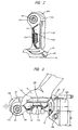
- FIG. 1A is a side view showing a torch light 10
- FIG. 1B is a front view showing the torch light 10.
- FIG. 1C is a cross-sectional view taken along a line A-A of FIG. 1B .
- FIG. 1A and FIG. 1B show a form of a case in which the torch light 10 is placed on a work table, a floor, or the like.
- FIG. 1B is a drawing showing the torch light 10 from the right side of FIG. 1A .
- the battery 100 can function as a base, and the torch light 10 can be placed on a working table or the like.
- the grip 11 is not positioned at a center part of the battery 100, but is positioned to be deviated to the right side with respect to the battery 100.
- the lower end (one end) of the grip 11 means a lower-side end part of the grip 11 shown in FIG. 1A .
- the upper end (the other end) of the grip 11 means an upper-side end part of the grip 11 shown in FIG. 1A .
- the rear side (one side) of the grip 11 means the right side of the grip 11 shown in FIG. 1A .
- the front side (the other side) of the grip 11 means the left side of the grip 11 shown in FIG. 1A .
- the rear side of the grip 11 means the side which contacts the palm of the operator when the operator holds the grip 11.
- the front side of the grip 11 means the side which contacts the fingers of the operator when the operator holds the grip 11.
- the torch light 10 has an irradiation-part base part 14, which is attached to the other end (upper end in FIG. 1A and FIG. 1B ) of the grip 11.
- the irradiation-part base part 14 is provided at the upper end of the grip 11.
- the irradiation-part base part 14 is provided at the other end of the grip 11 via a first turning shaft 13 and can be turned centering around the first turning shaft 13, in other words, can be turned about the first turning shaft 13.
- a long and thin irradiation-part distal end part 15 is attached to the irradiation-part base part 14.
- the irradiation directions of the light radiated from the irradiation part can be changed with respect to the grip 11 by turning the irradiation part centering around the first turning shaft 13.
- the first lamp 141 is provided at the grip 11-side end part of the irradiation part
- the second lamp 151 is provided on a side surface of the irradiation part.
- the irradiation-part distal end part 15 is formed to be long and thin along the grip 11. Therefore, the second lamp 151 is also formed to be long and thin along the grip 11.
- the second lamp 151 for example, a plurality of LEDs are arranged to be long and thin, and a lamp having a configuration in which these LEDs are covered with a long and thin lens can be used.
- the irradiation range (light projection range) of the second lamp 151 can be expanded.
- the second lamp 151 is suitable for irradiating a wide range, particularly.
- the irradiation-part base part 14 is formed so as to cover an upper end part of the grip 11. Therefore, it is difficult to form the first lamp 141 to be long and thin like the second lamp 151. Therefore, the first lamp 141 can use a light source of high luminance. However, the first lamp 141 uses a lens which is smaller than that of the second lamp 151. The first lamp 141 is suitable for particularly brightly irradiating a particular location.
- the first turning shaft 13 is fixed to the grip 11.
- the first turning shaft 13 is disposed in the direction perpendicular to the plane of the paper in the case shown in FIG. 1A and is disposed in a left-right direction in the case shown in FIG. 1B .
- the state shown in FIG. 1A is a state in which the irradiation-part base part 14 is turned about the first turning shaft 13 and the irradiation-part distal end part 15 is brought close to one side of the grip 11 along the longitudinal direction of the grip 11.
- FIG. 1A shows a state in which the irradiation-part base part 14 is turned about the first turning shaft 13 such that, in one side (right side in FIG.
- FIG. 1A also shows a state in which the irradiation parts 13 and 15 are turned to a second position at which they are extending from the upper end of the grip 11 toward the lower side.
- both of the longitudinal direction of the irradiation-part distal end part 15 and the longitudinal direction (axial direction of the grip 11) of the grip 11 are the vertical direction in the drawing.
- a switch 131 which switches the actuation state of the first lamp 141 and the second lamp 151, is provided at an end part of the first turning shaft 13.
- the switch 131 is operated when it is pushed in the axial direction of the first turning shaft 13.
- the switch 131 is a switch, which can switch whether the first lamp 141 is to carry out irradiation or the second lamp 151 is to carry out irradiation, and is provided at a position so that the switch can be operated from outside.
- the switch 131 is operated, the actuation state of the first lamp 141 and the second lamp 151 is cyclically changed.
- a state in which both of the first lamp 141 and the second lamp 151 do not light (are unlit)
- (2) a state in which only the first lamp 141 lights (3) a state in which only the second lamp 151 lights
- (4) a state in which both of the first lamp 141 and the second lamp 151 light (5) a state in which only the first lamp 141 flashes
- (6) a state in which only the second lamp 151 flashes or (7) a state in which both of the first lamp 141 and the second lamp 151 flash
- the irradiation-part distal end part 15 is provided on the irradiation-part base part 14 via a second turning shaft 16.
- the irradiation-part distal end part 15 can be turned about the second turning shaft 16 with respect to the irradiation-part base part 14.
- the second turning shaft 16 is fixed to the irradiation-part base part 14, and, in the form of FIG. 1A and FIG. 1B , the second turning shaft 16 is disposed along the vertical direction. In this manner, the first turning shaft 13 and the second turning shaft 16 are orthogonal to each other like a multilevel crossing.
- the irradiation-part base part 14 is turned about the first turning shaft 13 or in a case in which the irradiation-part distal end part 15 is turned about the second turning shaft 16, it is preferred to act predetermined turning resistance.
- the irradiation-part base part 14 or the irradiation-part distal end part 15 can be turned, and the irradiation-part base part 14 or the irradiation-part distal end part 15 can be fixed at a desired set angle.
- the right-side surface of the grip 11 in FIG. 1A in other words, the surface of the grip 11 in the side that abuts the irradiation-part distal end part 15 is an approximately flat surface or a curved surface having a large curvature radius.
- the left-side surface of the irradiation-part distal end part 15 in FIG. 1A in other words, the surface of the irradiation-part distal end part 15 in the side that abuts the grip 11 is an approximately flat surface or a curved surface having a large curvature radius.
- the surface of the irradiation-part distal end part 15 in the opposite side of the surface in the side that abuts the grip 11 has a curved-surface shape (curved-surface shape having a smaller curvature radius than the above-described curved surface having the large curvature radius) close to the curved surface forming an elliptical shape. Therefore, as shown in FIG. 1C , the overall cross section of the state in which the grip 11 and the irradiation-part distal end part 15 abut each other is formed so as to have an approximately elliptical shape. This cross-sectional shape and the size thereof are set so that the operator can hold the grip 11 and the irradiation-part distal end part 15 together.
- the shape of the grip 11 in the vertical direction in the right side in other words, the shape of the grip 11 in the vertical direction in the side of the irradiation-part distal end part 15 is an approximately linear shape in the longitudinal direction so as to cause the grip 11 and the irradiation-part distal end part 15 to abut each other.
- an elastic material (elastomer) 111 is attached so that the operator can easily hold the grip 11 from the side of the irradiation-part distal end part 15.
- the irradiation-part distal end part 15 is formed to be thinner than the grip 11, and the operator can hold only the grip 11.
- FIG. 1 shows a state in which the turning angle of the irradiation-part base part 14 about the first turning shaft 13 and the turning angle of the irradiation-part distal end part 15 about the second turning shaft 16 are set so that the torch light 10 has the most compact form. Therefore, when the torch light 10 is carried in an unused state, the form of FIG. 1 is normally employed.
- the battery 100 can be slid in the front-back direction (the direction shown by a white arrow).
- the battery 100 is moved along a rail provided in the side of the battery retaining part 12 and is fixed to the battery retaining part 12 at an appropriate position by a latch mechanism.
- This latch mechanism is released when latch release buttons 101 provided on the battery 100 are pushed.
- the latch release buttons 101 are provided not only in the side of the battery 100 shown in FIG. 1A , but also on the surface of the battery 100 in the opposite side. The operator detaches/attaches the battery 100 from/to the battery retaining part 12 while pushing these two latch release buttons 101.
- FIG. 2 is a drawing showing a form of the torch light 10 in which the battery 100 is detached from the battery retaining part 12 and is a drawing corresponding to FIG. 1A .
- the battery 100 is attached to the battery retaining part 12 from the left side of the drawing.
- the latch release buttons 101 are provided in the left side of the battery 100 in the drawing.
- a hook 17 is attached to the battery retaining part 12.
- the hook 17 is used for latching the torch light 10 to a projection provided on a wall or the like.
- the hook 17 is attached to the battery retaining part 12 via a wire (not shown).
- the hook 17 is housed in a hook housing opening 121, which is provided on the battery retaining part 12.
- the hook 17 is used in a case in which the torch light 10 is stored by hanging when it is not used or in a case in which the torch light 10 is used as illumination by hanging the torch light on the wall or the like.
- FIG. 3 is a drawing showing a situation in which the operator holds the torch light 10, which is in the form shown in FIG. 1 .
- the operator positioned in the right side of the drawing holds, by the hand H, the part at which the irradiation-part distal end part 15 and the grip 11 are integrated while the side of the battery 100 is in the near side.
- light can be emitted approximately forward (in the direction of a broken-line white arrow in FIG. 3 ) from the first lamp 141 of the torch light 10.
- the irradiation-part base part 14 is turned about the first turning shaft 13 in the state in which the grip 11 is held by the hand H, the direction of the light emitted by the first lamp 141 can be adjusted.
- FIG. 3 is a drawing showing a situation in which the operator holds the torch light 10, which is in the form shown in FIG. 1 .
- the operator positioned in the right side of the drawing holds, by the hand H, the part at which the irradiation-part distal end part 15 and
- the movable range of the irradiation-part base part 14 turned about the first turning shaft 13 is limited in a clockwise direction when the irradiation-part distal end part 15 abuts the upper side of the grip 11 as shown in FIG. 1A .
- the movable range is limited when the end part of the irradiation-part base part 14 in the counterclockwise-direction side abuts the grip 11.
- the case in which the turning angle of the irradiation-part base part 14 centering around the first turning shaft 13 is 180° is the turning limit of the irradiation-part base part 14 in the counterclockwise direction.
- the turning angle of the irradiation-part base part 14 about the first turning shaft 13 is adjusted, and the turning angle of the irradiation-part distal end part 15 about the second turning shaft 16 is adjusted.
- the turning angles of the irradiation-part base part 14 and the irradiation-part distal end part 15 are adjusted, in the rear side, the upper side, the front side, and the lower side, the directions in the range not interrupted by the grip 11, etc. can be irradiated by the second lamp 151.
- the states shown in FIG. 5A to FIG. 5D are the states after the irradiation-part distal end part 15 is turned by 180° about the second turning shaft 16 from the states shown in FIG. 4A to FIG. 4D .
- the turning angle of the irradiation-part distal end part 15 can be optionally set. Therefore, for example, the irradiation direction of the second lamp 151 can be changed to the near side with respect to the plane of the paper or the far side with respect to the plane of the paper in FIG. 4 and FIG. 5 , in other words, to the direction (lateral side of the torch light 10) parallel to the axial direction of the first turning shaft 13.
- the irradiation direction of the second lamp 151 can be changed to an oblique front side as shown in FIG. 6A and to an oblique rear side as shown in FIG. 6B when viewed from the operator.
- FIG. 7A and FIG. 7B show the positional relations between the torch light 10 and the operator in the cases in which the torch light 10 is in the forms of FIG. 6A and FIG. 6B .
- the irradiation direction of the second lamp 151 is the oblique rear side as shown in FIG.
- the operator holds the torch light 10 by the right hand, and an instruction manual held by the left hand can be irradiated by the second lamp 151 while operation equipment positioned in the front side of the operator is irradiated by the first lamp 141.
- an operation in a dark environment can be efficiently carried out by using the torch light 10.
- the grip 11 is deviated to the right side with respect to the battery 100. Therefore, as shown in FIG. 3 , the gravity center G of the torch light 10 is positioned below the central axis of the grip 11 in FIG. 3 . More specifically, when the irradiation-part distal end part 151 is folded down, the gravity center G of the torch light 10 is positioned to be deviated to the side (the other side of the grip) which is opposite to the side of the grip 11 abutting the irradiation-part distal end part 151. Therefore, in the forms of FIGS. 4A to 4D , FIGS. 5A to 5D , and FIGS 7A and 7B , the gravity center of the torch light 10 is at a low position, and the operator can stably hold the torch light 10.
- the projecting length of the battery 100 or the battery retaining part 12 is different in the upper side and the lower side of the grip 11. More specifically, the projecting length B in the upper side of the grip 11 is shorter than the projecting length C in the lower side of the grip 11. More specifically, the projecting length which is the distance between the battery 100 or the battery retaining part 12 and the grip is B which is the side in which the irradiation-part distal end part 15 is present (upper side in FIG. 3 : one side), and is C which is the opposite side thereof in which the irradiation-part distal end part 15 is not present (lower side in FIG. 3 : the other side).
- the projecting length B is shorter than the projecting length C (C>B).
- the distance B between the grip 11 in the upper side (one side) of the grip 11 and the portion of the battery 100 or the battery retaining part 12 which is the farthest from the grip 11 is shorter than the distance C between the grip 11 in the lower side (the other side) of the grip 11 and the portion of the battery 100 or the battery retaining part 12 which is the farthest from the grip 11.
- the above-described projecting distance is the distance between the portion of the battery 100 or the battery retaining part 12 which is the farthest from the grip 11 and the surface of the grip 11 when viewed from the axis connecting one end side and the other end side of the grip 11.
- the battery 100 is provided with the latch release buttons 101.
- the latch release buttons 101 are provided in the left side of the battery 100 in FIG. 1A .
- the latch release buttons 101 are provided in the side which is held when the battery 100 is attached.
- the latch release buttons 101 provided on the battery 100 are preferred to be positioned in the left side or the right side of the grip 11 in FIG. 1A .
- the latch release buttons 101 are preferred to be disposed in the left side in FIG. 1A . Therefore, it is particularly preferred that the battery 100 be attached to the battery retaining part 12 from the side to which the grip 11 deviates and is fixed (the right side in FIG. 1A ) or from the opposite side (the left side in FIG. 1A ) so as to facilitate carrying of the torch light 10 and facilitate detaching/attaching operations of the battery 100.
- FIG. 8A to FIG. 8D shows the state that the above-described torch light 10 is placed and that the irradiation-part distal end part 15 and the irradiation-part base part 14 are turned about the first turning shaft 13 from the state of FIG. 1A . More specifically, FIG. 8A to FIG. 8D respectively show the forms of the cases in which the irradiation-part distal end part 15 and the irradiation-part base part 14 are turned by 45°, 90°, 135°, and 180° counterclockwise from the state of FIG. 1A .
- FIG. 8D shows the state in which the irradiation parts 13 and 15 are turned to a first position at which they are extending from the upper end of the grip 11 to the upper side. Furthermore, FIG. 8B shows the state in which the irradiation parts 13 and 15 are turned to a third position at which they are extending from the upper end of the grip 11 to the rear side.
- the lower side to the right side in FIGS. 8A to 8D can be irradiated by the second lamp 151.
- FIGS. 5A to 5D it is obvious that the upper side to the front side in FIGS. 8A to 8D can be also irradiated by the second lamp 151 by turning the irradiation-part distal end part 15 about the second turning shaft 16. Therefore, as well as the cases shown in FIGS. 4A to 4D and FIGS. 5A to 5D , in other words, the cases in which the torch light 10 is carried and used, most directions can be irradiated by the second lamp 151 even when the torch light 10 is placed and used.
- the irradiation ranges in the side close to the grip 11 is limited by the grip 11, the battery retaining part 12, or the battery 100.
- the second lamp 151 irradiates immediately therebelow as shown in FIG. 8B light is interrupted by the battery retaining part 12 or the battery 100.
- the range in which the light is interrupted by the battery retaining part 12 or the battery 100 can be narrowed since the projecting length B is shorter than the projecting length C (C>B) in the torch light 10 as shown in FIG. 3 .
- the projection-light range toward the lower side can be expanded.
- Such a characteristic is particularly effective, for example, when the torch light 10 is placed on a work table to be used.
- the characteristic that various directions can be irradiated is realized by changing the form of the torch light 10 to the forms shown in FIGS. 1A and 1B and the forms shown in FIGs. 8A to 8D . More specifically, the characteristic of irradiating wide directions is realized, since the form in which the irradiation-part distal end part 15 is disposed along the grip 11 (the form shown in FIGs. 1A and 1B ) can be changed to the form in which the irradiation-part distal end part 15 is turned about the first turning shaft 13 so as to be distant from the grip 11 (the forms shown in FIG. 8A to 8D ). In the forms shown in FIGS.
- the torch light 10 is hung by using the hook 17. Therefore, when the turning angles of the irradiation-part base part 14 and the irradiation-part distal end part 15 are set as shown in FIGS. 4A to 4D and FIGS. 5A to 5D in the state in which the torch light 10 is hung, a wide range can be similarly irradiated by the torch light 10.
- the above-described examples employ the structure in which the first turning shaft 13 and the second turning shaft 16 are orthogonal to each other like a multilevel crossing.
- the first turning shaft 13 and the second turning shaft 16 are not required to be orthogonal to each other.
- Wide ranges can be irradiated in various modes by using the first lamp and the second lamp in the same manner as above, as long as the second turning shaft is set so as to intersect with the flat surface along which the irradiation-part base part is moved when the irradiation-part base part is turned about the first turning shaft, and as long as the second turning shaft is fixed to the irradiation-part base part.
- the irradiation part is connected to the grip so that the irradiation part can be turned between the first position, the second position, and a third position extending from the upper end of the grip to a rear side, and the battery is disposed to be shifted to a front side with respect to the grip.
Landscapes
- Engineering & Computer Science (AREA)
- General Engineering & Computer Science (AREA)
- Non-Portable Lighting Devices Or Systems Thereof (AREA)
- Fastening Of Light Sources Or Lamp Holders (AREA)
Abstract
Description
- The present invention relates to an illuminating device that radiates light.
- Examples of an illuminating device that is carried by an operator and can illuminate a desired location include torch lights. Torch lights are used for assisting operations in various operation environments. As the torch lights, those in various forms are known. For example, US Patent Application Publication No.
US 2008/0304254 A1 (Patent Document 1) describes a torch light provided with a lamp, which irradiates a wide range, and a lamp, which particularly brightly irradiates a narrow range. The torch light ofPatent Document 1 has a housing, which is provided with the two lamps, and a grip, which is held by an operator. In the torch light ofPatent Document 1, the housing and the grip are turnably coupled. In the torch light having such a structure, a set angle of the housing is adjusted by the operator, and the lamps of two types are used depending on the use. Therefore, the torch light can be used in an optimum form in an operation. - For example, in a case in which a torch light is used at an outdoor workplace, the places illuminated by the torch light are various. Therefore, torch lights are installed at various places in various forms. For example, there are cases in which torch lights are placed on a floor, a desk, etc. and used thereon. On the other hand, torch lights are carried and used by operators in some cases. In this manner, illuminating devices such as torch lights have been required to appropriately illuminate desired ranges depending on various situations.
- Further, even when a torch light is carried and used, the usage mode thereof is various. For example, there is a case in which an apparatus is operated while an operator sees an instruction manual in a situation in which there is no illuminating device except for the torch light. In such a case, it is required to appropriately illuminate a plurality of locations at the same time.
- As a power source of a torch light, a dry battery or the like can be used. However, for example in a case in which it is used in an outdoor operation, in order to improve convenience, it is preferred to use a high-capacity battery shared by other electric operation equipment (cordless driver, etc.) as the power source of the torch light. In the case in which the high-capacity battery is used, compared with the case in which a dry battery or the like is used as the power source, continuously-usable time of the torch light can be extended. However, since such a battery is large and heavy compared with the dry battery or the like, it is difficult to employ a long and thin form which can be easily handled as described in
Patent Document 1. Therefore, using an illuminating device such as a torch light to which a battery is attached in the above-described various modes has made it difficult to handle the illuminating device for the operator. - In this manner, it has been difficult to obtain an illuminating device that can support various usage modes and carry out optimum illumination.
- The present invention has been accomplished in view of such problems, and it is an object to provide the invention that solves the above-described problems.
- In order to solve the above problem, the present invention provides configurations described below.
- According to an embodiment of the present invention, an illuminating device includes: a grip held by an operator and extending in a vertical direction; a battery connected to a lower end of the grip; and an irradiation part connected to an upper end of the grip. The irradiation part is connected to the grip so that the irradiation part can be turned between a first position extending from the upper end of the grip to an upper side and a second position extending from the upper end of the grip to a lower side, a first lamp is provided on a grip-side end part of the irradiation part, and a second lamp is provided on a side surface of the irradiation part.
- According to another embodiment of the present invention, an illuminating device includes: a grip held by an operator and extending in a vertical direction; a battery connected to a lower end of the grip; and an irradiation part connected to an upper end of the grip. The irradiation part is connected to the grip so that the irradiation part can be turned between a first position extending from the upper end of the grip to an upper side, a second position extending from the upper end of the grip to a lower side, and a third position extending from the upper end of the grip to a rear side, and the battery is disposed to be shifted to a front side with respect to the grip.
- According to another embodiment of the present invention, an illuminating device includes: a grip held by an operator and extending in a vertical direction; a battery connected to a lower end of the grip; and an irradiation part connected to an upper end of the grip. The irradiation part is provided with a second lamp that irradiates a rear side of the grip, and the battery is disposed to be shifted to a front side with respect to the grip.
- According to another embodiment of the present invention, an illuminating device includes: a grip held by an operator and extending in a vertical direction; a battery connected to a lower end of the grip; and an irradiation part connected to an upper end of the grip. The irradiation part is connected to the grip so that the irradiation part can be turned between a first position extending from the upper end of the grip to an upper side and a second position extending from the upper end of the grip to a lower side, the irradiation part is provided with a first lamp and a second lamp that irradiates a direction intersecting with a direction irradiated by the first lamp, and a switch capable of switching whether the first lamp is to carry out irradiation or the second lamp is to carry out irradiation is provided at a position at which the switch can be operated from outside even in a state that the irradiation part is at the second position.
- According to another embodiment of the present invention, an illuminating device that has a battery retaining part retaining a battery provided at one end side of a grip held by an operator and radiates light by a lamp that can change an irradiation direction of the light with respect to the grip, the illuminating device includes a first lamp and a second lamp as the lamp, the first lamp is provided on an irradiation-part base part that is provided at the other end side of the grip via a first turning shaft and that can be turned about the first turning shaft, and the second lamp is provided at an irradiation-part distal end part that is provided on the irradiation-part base part via a second turning shaft and that can be turned about the second turning shaft.
- According to another embodiment of the present invention, an illuminating device has a battery retaining part retaining a battery provided at one end side of a grip held by an operator and radiates light by a lamp that can change an irradiation direction of the light with respect to the grip. The lamp is provided on an irradiation part that is provided at the other end side of the grip via a first turning shaft and that can be turned about the first turning shaft, when the irradiation part is turned about the first turning shaft, the irradiation part is brought close to one side of the grip in a longitudinal direction of the grip, and a distance between the grip and a portion of the battery or of the battery retaining part that is the farthest from the grip in one side of the grip is shorter than a distance between the grip and a portion of the battery or of the battery retaining part that is the farthest from the grip in the other side of the grip.
- Since the present invention is configured in the above-described manner, an illuminating device that can carry out optimum illumination corresponding to various usage modes can be obtained.
-
-
FIG. 1A is a side view of a torch light according to an embodiment of the present invention; -
FIG. 1B is a front view thereof; -
FIG. 1C is a cross-sectional view thereof; -
FIG. 2 is a side view showing a form of a case in which a battery is not attached in the torch light according to the embodiment of the present invention; -
FIG. 3 is a side view showing a configuration of a case in which the torch light according to the embodiment of the present invention is carried; -
FIGS. 4A to 4D are drawings showing configurations of the cases in which the turning angle about a first turning shaft is adjusted when the torch light according to the embodiment of the present invention is carried and used; -
FIGS. 5A to 5D are drawings showing configurations of the cases in which the turning angle about the first turning shaft is adjusted when the torch light according to the embodiment of the present invention is carried and used; -
FIGS. 6A and 6B are drawings showing configurations of the cases in which the turning angles about the first turning shaft and a second turning shaft are adjusted in the torch light according to the embodiment of the present invention; -
FIGS. 7A and 7B are drawings showing configurations of the cases in which the torch light according to the embodiment of the present invention is carried in the states in which the turning angles about the first turning shaft and the second turning shaft are adjusted; -
FIGS. 8A to 8D are drawings showing configurations of the cases in which the turning angle about the first turning shaft is adjusted when the torch light according to the embodiment of the present invention is placed and used; -
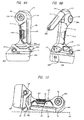
FIG. 9A is a side view of a modification example of the torch light according to the embodiment of the present invention; -
FIG. 9B is a perspective view thereof; and -
FIG. 10 is a drawing showing a form of a case in which the modification example of the torch light according to the embodiment of the present invention is placed on a flat surface. - A torch light (illuminating device), which is an embodiment of the present invention, will be explained. The torch light uses an attachable/detachable high-capacity battery as a power source. The torch light is provided with, as lamps which radiate light, a first lamp that has a wide irradiation angle and a second lamp that particularly brightly irradiates a range narrower than such an irradiation angle. The set angles (irradiation directions) of the first lamp and the second lamp are appropriately set depending on the usage mode of an operator. It is also possible to simultaneously adjust the first lamp and the second lamp to optimum set angles and simultaneously use the first lamp and the second lamp.
-
FIG. 1A is a side view showing atorch light 10, andFIG. 1B is a front view showing thetorch light 10.FIG. 1C is a cross-sectional view taken along a line A-A ofFIG. 1B . Herein,FIG. 1A and FIG. 1B show a form of a case in which thetorch light 10 is placed on a work table, a floor, or the like.FIG. 1B is a drawing showing the torch light 10 from the right side ofFIG. 1A . - As shown in
FIG. 1A and FIG. 1B , thetorch light 10 has agrip 11 extending in a vertical direction. At one end (lower end inFIG. 1A and FIG. 1B ) of thegrip 11, abattery retaining part 12, which is thicker than thegrip 11, is provided. In other words, as shown inFIG. 1A and FIG. 1B , thebattery retaining part 12 is provided at the lower end of thegrip 11. Abattery 100, which is a power source, is attached to thebattery retaining part 12. As shown in the drawing, the width of thebattery 100 is formed to be wider and heavier than thegrip 11. Therefore, in a state in which thebattery 100 is attached to thebattery retaining part 12, thebattery 100 can function as a base, and thetorch light 10 can be placed on a working table or the like. As shown inFIG. 1A , thegrip 11 is not positioned at a center part of thebattery 100, but is positioned to be deviated to the right side with respect to thebattery 100. - In the present specification, the lower end (one end) of the
grip 11 means a lower-side end part of thegrip 11 shown inFIG. 1A . The upper end (the other end) of thegrip 11 means an upper-side end part of thegrip 11 shown inFIG. 1A . The rear side (one side) of thegrip 11 means the right side of thegrip 11 shown inFIG. 1A . The front side (the other side) of thegrip 11 means the left side of thegrip 11 shown inFIG. 1A . In other words, the rear side of thegrip 11 means the side which contacts the palm of the operator when the operator holds thegrip 11. The front side of thegrip 11 means the side which contacts the fingers of the operator when the operator holds thegrip 11. - The
torch light 10 has an irradiation-part base part 14, which is attached to the other end (upper end inFIG. 1A and FIG. 1B ) of thegrip 11. In other words, as shown inFIG. 1A and FIG. 1B , the irradiation-part base part 14 is provided at the upper end of thegrip 11. The irradiation-part base part 14 is provided at the other end of thegrip 11 via afirst turning shaft 13 and can be turned centering around thefirst turning shaft 13, in other words, can be turned about thefirst turning shaft 13. A long and thin irradiation-partdistal end part 15 is attached to the irradiation-part base part 14. In thistorch light 10, the irradiation-part base part 14 and the irradiation-partdistal end part 15 constitute an irradiation part. The irradiation-part base part 14 is provided with afirst lamp 141, and the irradiation-partdistal end part 15 is provided with asecond lamp 151. In other words, the irradiation part provided with the irradiation-part base part 14 and the irradiation-partdistal end part 15 is connected to the upper end of thegrip 11. Moreover, in the irradiation part, thefirst lamp 141 and thesecond lamp 151 are provided as lamps, which radiate light. The irradiation directions of the light radiated from the irradiation part can be changed with respect to thegrip 11 by turning the irradiation part centering around thefirst turning shaft 13. In other words, thefirst lamp 141 is provided at the grip 11-side end part of the irradiation part, and thesecond lamp 151 is provided on a side surface of the irradiation part. - As shown in
FIG. 1A , the irradiation-partdistal end part 15 is formed to be long and thin along thegrip 11. Therefore, thesecond lamp 151 is also formed to be long and thin along thegrip 11. As thesecond lamp 151, for example, a plurality of LEDs are arranged to be long and thin, and a lamp having a configuration in which these LEDs are covered with a long and thin lens can be used. By virtue of such a configuration, the irradiation range (light projection range) of thesecond lamp 151 can be expanded. Thesecond lamp 151 is suitable for irradiating a wide range, particularly. - On the other hand, as shown in
FIG. 1A , the irradiation-part base part 14 is formed so as to cover an upper end part of thegrip 11. Therefore, it is difficult to form thefirst lamp 141 to be long and thin like thesecond lamp 151. Therefore, thefirst lamp 141 can use a light source of high luminance. However, thefirst lamp 141 uses a lens which is smaller than that of thesecond lamp 151. Thefirst lamp 141 is suitable for particularly brightly irradiating a particular location. - The
first turning shaft 13 is fixed to thegrip 11. Thefirst turning shaft 13 is disposed in the direction perpendicular to the plane of the paper in the case shown inFIG. 1A and is disposed in a left-right direction in the case shown inFIG. 1B . The state shown inFIG. 1A is a state in which the irradiation-part base part 14 is turned about thefirst turning shaft 13 and the irradiation-partdistal end part 15 is brought close to one side of thegrip 11 along the longitudinal direction of thegrip 11. In other words,FIG. 1A shows a state in which the irradiation-part base part 14 is turned about thefirst turning shaft 13 such that, in one side (right side inFIG. 1A ) of thegrip 11, the irradiation-partdistal end part 15 abuts thegrip 11 in the longitudinal direction thereof or the irradiation-partdistal end part 15 is the closest to thegrip 11 along the longitudinal direction thereof.FIG. 1A also shows a state in which theirradiation parts grip 11 toward the lower side. In the state shown inFIG. 1A , both of the longitudinal direction of the irradiation-partdistal end part 15 and the longitudinal direction (axial direction of the grip 11) of thegrip 11 are the vertical direction in the drawing. - A
switch 131, which switches the actuation state of thefirst lamp 141 and thesecond lamp 151, is provided at an end part of thefirst turning shaft 13. Theswitch 131 is operated when it is pushed in the axial direction of thefirst turning shaft 13. In other words, theswitch 131 is a switch, which can switch whether thefirst lamp 141 is to carry out irradiation or thesecond lamp 151 is to carry out irradiation, and is provided at a position so that the switch can be operated from outside. When theswitch 131 is operated, the actuation state of thefirst lamp 141 and thesecond lamp 151 is cyclically changed. For example, as the actuation state, (1) a state in which both of thefirst lamp 141 and thesecond lamp 151 do not light (are unlit), (2) a state in which only thefirst lamp 141 lights, (3) a state in which only thesecond lamp 151 lights, (4) a state in which both of thefirst lamp 141 and thesecond lamp 151 light, (5) a state in which only thefirst lamp 141 flashes, (6) a state in which only thesecond lamp 151 flashes, or (7) a state in which both of thefirst lamp 141 and thesecond lamp 151 flash can be set. Other than these, it may be set so that the illuminance of thefirst lamp 141 and thesecond lamp 151 is adjusted by operating theswitch 131. - As shown by broken lines in
FIG. 1A and FIG. 1B , the irradiation-partdistal end part 15 is provided on the irradiation-part base part 14 via asecond turning shaft 16. Thus, the irradiation-partdistal end part 15 can be turned about thesecond turning shaft 16 with respect to the irradiation-part base part 14. Thesecond turning shaft 16 is fixed to the irradiation-part base part 14, and, in the form ofFIG. 1A and FIG. 1B , thesecond turning shaft 16 is disposed along the vertical direction. In this manner, thefirst turning shaft 13 and thesecond turning shaft 16 are orthogonal to each other like a multilevel crossing. The changes in the form of thetorch light 10 in the case in which the irradiation-part base part 14 is turned about thefirst turning shaft 13 or in the case in which the irradiation-partdistal end part 15 is turned about thesecond turning shaft 16 will be described later. In the form ofFIG. 1A , since thesecond lamp 151 abuts thegrip 11, illumination using thesecond lamp 151 is not carried out. - In a case in which the irradiation-
part base part 14 is turned about thefirst turning shaft 13 or in a case in which the irradiation-partdistal end part 15 is turned about thesecond turning shaft 16, it is preferred to act predetermined turning resistance. By virtue of this, only in the case in which the force having a predetermined magnitude or more works, the irradiation-part base part 14 or the irradiation-partdistal end part 15 can be turned, and the irradiation-part base part 14 or the irradiation-partdistal end part 15 can be fixed at a desired set angle. Alternatively, it is possible to fix the irradiation-part base part 14 or the irradiation-partdistal end part 15 at a desired set angle by providing a fixing mechanism that fixes the irradiation-part base part 14 or the irradiation-partdistal end part 15, and the irradiation-part base part 14 or the irradiation-partdistal end part 15 may be turned with small force. - The right-side surface of the
grip 11 inFIG. 1A , in other words, the surface of thegrip 11 in the side that abuts the irradiation-partdistal end part 15 is an approximately flat surface or a curved surface having a large curvature radius. The left-side surface of the irradiation-partdistal end part 15 inFIG. 1A , in other words, the surface of the irradiation-partdistal end part 15 in the side that abuts thegrip 11 is an approximately flat surface or a curved surface having a large curvature radius. On the other hand, the left-side surface of thegrip 11 inFIG. 1A , in other words, the surface of thegrip 11 in the opposite side of the surface in the side that abuts the irradiation-partdistal end part 15 has a curved-surface shape (a curved-surface shape having a smaller curvature radius than the above-described curved surface having the large curvature radius) close to a curved surface forming an elliptical shape. The left-side surface of the irradiation-partdistal end part 15 inFIG. 1A , in other words, the surface of the irradiation-partdistal end part 15 in the opposite side of the surface in the side that abuts thegrip 11 has a curved-surface shape (curved-surface shape having a smaller curvature radius than the above-described curved surface having the large curvature radius) close to the curved surface forming an elliptical shape. Therefore, as shown inFIG. 1C , the overall cross section of the state in which thegrip 11 and the irradiation-partdistal end part 15 abut each other is formed so as to have an approximately elliptical shape. This cross-sectional shape and the size thereof are set so that the operator can hold thegrip 11 and the irradiation-partdistal end part 15 together. As shown inFIG. 1A , the shape of thegrip 11 in the vertical direction in the right side, in other words, the shape of thegrip 11 in the vertical direction in the side of the irradiation-partdistal end part 15 is an approximately linear shape in the longitudinal direction so as to cause thegrip 11 and the irradiation-partdistal end part 15 to abut each other. As shown inFIG. 1A , in the left side of thegrip 11, in other words, in the side of thegrip 11 opposite to the side of the irradiation-partdistal end part 15, an elastic material (elastomer) 111 is attached so that the operator can easily hold thegrip 11 from the side of the irradiation-partdistal end part 15. As shown inFIG. 1C , the irradiation-partdistal end part 15 is formed to be thinner than thegrip 11, and the operator can hold only thegrip 11. - The form of
FIG. 1 shows a state in which the turning angle of the irradiation-part base part 14 about thefirst turning shaft 13 and the turning angle of the irradiation-partdistal end part 15 about thesecond turning shaft 16 are set so that thetorch light 10 has the most compact form. Therefore, when thetorch light 10 is carried in an unused state, the form ofFIG. 1 is normally employed. - In the state of
FIG. 1A , thebattery 100 can be slid in the front-back direction (the direction shown by a white arrow). By virtue of this, thebattery 100 is moved along a rail provided in the side of thebattery retaining part 12 and is fixed to thebattery retaining part 12 at an appropriate position by a latch mechanism. This latch mechanism is released whenlatch release buttons 101 provided on thebattery 100 are pushed. Thelatch release buttons 101 are provided not only in the side of thebattery 100 shown inFIG. 1A , but also on the surface of thebattery 100 in the opposite side. The operator detaches/attaches thebattery 100 from/to thebattery retaining part 12 while pushing these twolatch release buttons 101.FIG. 2 is a drawing showing a form of thetorch light 10 in which thebattery 100 is detached from thebattery retaining part 12 and is a drawing corresponding toFIG. 1A . InFIG. 1A , thebattery 100 is attached to thebattery retaining part 12 from the left side of the drawing. In order to facilitate this operation, thelatch release buttons 101 are provided in the left side of thebattery 100 in the drawing. - A
hook 17 is attached to thebattery retaining part 12. Thehook 17 is used for latching thetorch light 10 to a projection provided on a wall or the like. Thehook 17 is attached to thebattery retaining part 12 via a wire (not shown). When thehook 17 is not used, thehook 17 is housed in ahook housing opening 121, which is provided on thebattery retaining part 12. Thehook 17 is used in a case in which thetorch light 10 is stored by hanging when it is not used or in a case in which thetorch light 10 is used as illumination by hanging the torch light on the wall or the like. - Regarding the above-described torch light 10, the operator can carry and use the
torch light 10 and also can use thetorch light 10 while the torch light is placed on a work table or the like. In either case, the direction illuminated by thetorch light 10 can be adjusted to an optimum direction in an operation. Hereinafter, a mode of a case in which the operator carries and uses thetorch light 10 will be explained. In this case, thesecond lamp 151 and thefirst lamp 141 can be simultaneously used for illumination. -
FIG. 3 is a drawing showing a situation in which the operator holds thetorch light 10, which is in the form shown inFIG. 1 . As shown inFIG. 3 , the operator positioned in the right side of the drawing holds, by the hand H, the part at which the irradiation-partdistal end part 15 and thegrip 11 are integrated while the side of thebattery 100 is in the near side. As a result, light can be emitted approximately forward (in the direction of a broken-line white arrow inFIG. 3 ) from thefirst lamp 141 of thetorch light 10. When the irradiation-part base part 14 is turned about thefirst turning shaft 13 in the state in which thegrip 11 is held by the hand H, the direction of the light emitted by thefirst lamp 141 can be adjusted.FIG. 4A to FIG. 4D respectively show the forms of the cases in which the turning angle of the irradiation-part base part 14 are changed by 45°, 90°, 135°, and 180° counterclockwise from the state ofFIG. 3 . In this manner, the direction of the light emitted from thefirst lamp 141 can be adjusted by turning the irradiation-part base part 14 centering around thefirst turning shaft 13. Irradiation by thesecond lamp 151 cannot be practically carried out by the form shown inFIG. 3 ; on the other hand, in the forms shown inFIG. 4A to FIG. 4D , irradiation from the rear side to the upper side can be carried out. - The movable range of the irradiation-
part base part 14 turned about thefirst turning shaft 13 is limited in a clockwise direction when the irradiation-partdistal end part 15 abuts the upper side of thegrip 11 as shown inFIG. 1A . On the other hand, in the counterclockwise direction, the movable range is limited when the end part of the irradiation-part base part 14 in the counterclockwise-direction side abuts thegrip 11. In the case shown in the figure, as shown inFIG. 4D , the case in which the turning angle of the irradiation-part base part 14 centering around thefirst turning shaft 13 is 180° is the turning limit of the irradiation-part base part 14 in the counterclockwise direction. The counterclockwise-direction movable range of the irradiation-part base part 14 can be set to be larger than 180° depending on the structure of the irradiation-part base part 14. However, it is difficult to set the counterclockwise-direction turning angle of the irradiation-part base part 14 to nearly 360°. Therefore, in the form shown inFIG. 4A to FIG. 4D , it is difficult to irradiate the front side or the lower side by thesecond lamp 151. - On the other hand, the irradiation-part
distal end part 15 can be turned centering around thesecond turning shaft 16 with respect to the irradiation-part base part 14. Each ofFIG. 5A to FIG. 5D shows the states in which the irradiation-partdistal end part 15 is turned by 180° about thesecond turning shaft 16 from the states shown in each ofFIG. 4A to FIG. 4B . In this case, light can be irradiated from the upper side to the front side and from the front side to the lower side by using thesecond lamp 151 by adjusting the turning angle of the irradiation-part base part 14, which is turned centering around thefirst turning shaft 13. More specifically, in a state in which the operator is holding thegrip 11, the turning angle of the irradiation-part base part 14 about thefirst turning shaft 13 is adjusted, and the turning angle of the irradiation-partdistal end part 15 about thesecond turning shaft 16 is adjusted. In this manner, when the turning angles of the irradiation-part base part 14 and the irradiation-partdistal end part 15 are adjusted, in the rear side, the upper side, the front side, and the lower side, the directions in the range not interrupted by thegrip 11, etc. can be irradiated by thesecond lamp 151. - The states shown in
FIG. 5A to FIG. 5D are the states after the irradiation-partdistal end part 15 is turned by 180° about thesecond turning shaft 16 from the states shown inFIG. 4A to FIG. 4D . However, in practice, the turning angle of the irradiation-partdistal end part 15 can be optionally set. Therefore, for example, the irradiation direction of thesecond lamp 151 can be changed to the near side with respect to the plane of the paper or the far side with respect to the plane of the paper inFIG. 4 andFIG. 5 , in other words, to the direction (lateral side of the torch light 10) parallel to the axial direction of thefirst turning shaft 13. - Therefore, the irradiation direction of the
second lamp 151 can be changed to an oblique front side as shown inFIG. 6A and to an oblique rear side as shown inFIG. 6B when viewed from the operator.FIG. 7A and FIG. 7B show the positional relations between thetorch light 10 and the operator in the cases in which thetorch light 10 is in the forms ofFIG. 6A and FIG. 6B . Particularly in the case in which the irradiation direction of thesecond lamp 151 is the oblique rear side as shown inFIG. 7B , for example, the operator holds thetorch light 10 by the right hand, and an instruction manual held by the left hand can be irradiated by thesecond lamp 151 while operation equipment positioned in the front side of the operator is irradiated by thefirst lamp 141. Thus, an operation in a dark environment can be efficiently carried out by using thetorch light 10. - As shown in
FIG. 1A , thegrip 11 is deviated to the right side with respect to thebattery 100. Therefore, as shown inFIG. 3 , the gravity center G of thetorch light 10 is positioned below the central axis of thegrip 11 inFIG. 3 . More specifically, when the irradiation-partdistal end part 151 is folded down, the gravity center G of thetorch light 10 is positioned to be deviated to the side (the other side of the grip) which is opposite to the side of thegrip 11 abutting the irradiation-partdistal end part 151. Therefore, in the forms ofFIGS. 4A to 4D ,FIGS. 5A to 5D , andFIGS 7A and 7B , the gravity center of thetorch light 10 is at a low position, and the operator can stably hold thetorch light 10. - As shown in
FIG. 3 , the projecting length of thebattery 100 or thebattery retaining part 12 is different in the upper side and the lower side of thegrip 11. More specifically, the projecting length B in the upper side of thegrip 11 is shorter than the projecting length C in the lower side of thegrip 11. More specifically, the projecting length which is the distance between thebattery 100 or thebattery retaining part 12 and the grip is B which is the side in which the irradiation-partdistal end part 15 is present (upper side inFIG. 3 : one side), and is C which is the opposite side thereof in which the irradiation-partdistal end part 15 is not present (lower side inFIG. 3 : the other side). Since thegrip 11 is deviated to the right side with respect to thebattery 100 as shown inFIG. 1A , the projecting length B is shorter than the projecting length C (C>B). In other words, the distance B between thegrip 11 in the upper side (one side) of thegrip 11 and the portion of thebattery 100 or thebattery retaining part 12 which is the farthest from thegrip 11 is shorter than the distance C between thegrip 11 in the lower side (the other side) of thegrip 11 and the portion of thebattery 100 or thebattery retaining part 12 which is the farthest from thegrip 11. The above-described projecting distance is the distance between the portion of thebattery 100 or thebattery retaining part 12 which is the farthest from thegrip 11 and the surface of thegrip 11 when viewed from the axis connecting one end side and the other end side of thegrip 11. - In this manner, in one side and the other side of the
grip 11, the projecting lengths of thebattery 100, etc. are different. Therefore, as shown inFIGS. 4A to 4D ,FIG. 5A to 5D , andFIGs. 7A and 7B , when the operator holds thegrip 11 from the side in which the irradiation-partdistal end part 15 is present, in other words, from the side in which the projecting length of thebattery 100, etc. is short, the hand does not easily contact thebattery 100 and thebattery retaining part 12. In the state ofFIG. 1A in which the irradiation-partdistal end part 15 is along thegrip 11, the operator holds the cross-sectional structure consisting of the irradiation-partdistal end part 15 and the grip 11 (the structure shown inFIG. 1C ); therefore, the hand that holds this structure further does not easily abut thebattery 100 and thebattery retaining part 12. Therefore, regardless of the set angle of the irradiation-partdistal end part 15, the operator can easily carry thetorch light 10. In this case, since theelastic material 111 is provided at the part to which load is applied the most by the hand holding thegrip 11, carrying of thetorch light 10 is further facilitated by theelastic material 111. - As shown in
FIG. 1A , thebattery 100 is provided with thelatch release buttons 101. When thebattery 100 is to be detached/attached, the operator slides thebattery 100 while pushing thelatch release buttons 101. As described above, thelatch release buttons 101 are provided in the left side of thebattery 100 inFIG. 1A . In other words, thelatch release buttons 101 are provided in the side which is held when thebattery 100 is attached. In order to maintain the total height of thetorch light 10 inFIG. 1A to be low and facilitate the operation of thelatch release buttons 101 by the operator, thelatch release buttons 101 provided on thebattery 100 are preferred to be positioned in the left side or the right side of thegrip 11 inFIG. 1A . In this case, in order to set the projecting length of thebattery 100 or thebattery retaining part 12 to be C>B as described above, it is obvious that thelatch release buttons 101 are preferred to be disposed in the left side inFIG. 1A . Therefore, it is particularly preferred that thebattery 100 be attached to thebattery retaining part 12 from the side to which thegrip 11 deviates and is fixed (the right side inFIG. 1A ) or from the opposite side (the left side inFIG. 1A ) so as to facilitate carrying of thetorch light 10 and facilitate detaching/attaching operations of thebattery 100. - Next, a mode of a case in which the above-described torch light 10 is placed on a work table or the like to be used will be explained. In this case, when the
torch light 10 is placed so that thebattery 100 contacts the ground or the like as shown inFIG. 1A and FIG. 1B , thebattery 100 can be particularly stably placed. - In this case, the
second lamp 151, which has a large light-projection area since it has a large area, can be mainly used. Each ofFIG. 8A to FIG. 8D shows the state that the above-described torch light 10 is placed and that the irradiation-partdistal end part 15 and the irradiation-part base part 14 are turned about thefirst turning shaft 13 from the state ofFIG. 1A . More specifically,FIG. 8A to FIG. 8D respectively show the forms of the cases in which the irradiation-partdistal end part 15 and the irradiation-part base part 14 are turned by 45°, 90°, 135°, and 180° counterclockwise from the state ofFIG. 1A .FIG. 8D shows the state in which theirradiation parts grip 11 to the upper side. Furthermore,FIG. 8B shows the state in which theirradiation parts grip 11 to the rear side. - In the cases shown in
FIG. 8A to FIG. 8D , the lower side to the right side inFIGS. 8A to 8D can be irradiated by thesecond lamp 151. As well asFIGS. 5A to 5D , it is obvious that the upper side to the front side inFIGS. 8A to 8D can be also irradiated by thesecond lamp 151 by turning the irradiation-partdistal end part 15 about thesecond turning shaft 16. Therefore, as well as the cases shown inFIGS. 4A to 4D andFIGS. 5A to 5D , in other words, the cases in which thetorch light 10 is carried and used, most directions can be irradiated by thesecond lamp 151 even when thetorch light 10 is placed and used. - However, in the cases in which the lower side is irradiated by the
second lamp 151 as shown inFIGS. 8B and 8C , as shown by broken lines, the irradiation ranges in the side close to thegrip 11 is limited by thegrip 11, thebattery retaining part 12, or thebattery 100. Particularly in the case in which thesecond lamp 151 irradiates immediately therebelow as shown inFIG. 8B , light is interrupted by thebattery retaining part 12 or thebattery 100. Regarding this point, the range in which the light is interrupted by thebattery retaining part 12 or thebattery 100 can be narrowed since the projecting length B is shorter than the projecting length C (C>B) in thetorch light 10 as shown inFIG. 3 . Thus, when thetorch light 10 is placed and used, the projection-light range toward the lower side can be expanded. Such a characteristic is particularly effective, for example, when thetorch light 10 is placed on a work table to be used. - In this manner, the characteristic that various directions can be irradiated is realized by changing the form of the
torch light 10 to the forms shown inFIGS. 1A and 1B and the forms shown inFIGs. 8A to 8D . More specifically, the characteristic of irradiating wide directions is realized, since the form in which the irradiation-partdistal end part 15 is disposed along the grip 11 (the form shown inFIGs. 1A and 1B ) can be changed to the form in which the irradiation-partdistal end part 15 is turned about thefirst turning shaft 13 so as to be distant from the grip 11 (the forms shown inFIG. 8A to 8D ). In the forms shown inFIGS. 1A and 1B , the irradiation-partdistal end part 15 is provided along the side in which, when viewed from the axis of thegrip 11, projections of thebattery retaining part 12 and thebattery 100 from thegrip 11 are small. In the forms shown inFIGS. 8A to 8D , thefirst turning shaft 13 serving as a turning center is provided in the side opposite to thebattery retaining part 12. - Thus, regarding the above-described torch light 10, both in the state in which the
torch light 10 is carried by the operator and in the case in which thetorch light 10 is placed, a wide range can be set as the directions irradiated by thesecond lamp 151.FIGS. 8A to 8D describe only the irradiation by thesecond lamp 151; however, it is obvious that the irradiation directions of thefirst lamp 141 are similarly set. More specifically, it is obvious that thefirst lamp 141 can be used not only in the case in which thetorch light 10 is held by the operator, but also in the state in which thetorch light 10 is placed. - As described above, the
torch light 10 is hung by using thehook 17. Therefore, when the turning angles of the irradiation-part base part 14 and the irradiation-partdistal end part 15 are set as shown inFIGS. 4A to 4D andFIGS. 5A to 5D in the state in which thetorch light 10 is hung, a wide range can be similarly irradiated by thetorch light 10. - Next, modification examples of the above-described torch light 10 will be explained. In the above-described torch light 10, the
first lamp 141 and thesecond lamp 151 are used. However, in order to improve convenience, a third lamp can be further provided.FIG. 9A is a side view showing the structure of atorch light 110, which is a modification example, andFIG. 9B is a perspective view showing the structure of thetorch light 110.FIG. 9A shows the same form as that ofFIG. 1A . - In the
torch light 110, the structures such as thegrip 11, thebattery retaining part 12, thebattery 100, thefirst turning shaft 13, the irradiation-part base part 14, and thehook 17 are similar to those of the above-described torch light 10. Moreover, although not shown in the figure, thetorch light 110 is also provided with a second turning shaft, as in thetorch light 10. However, although the irradiation-partdistal end part 25 provided in thetorch light 110 is provided with the above-describedsecond lamp 151, athird lamp 251 is further provided at a tip of the irradiation-partdistal end part 25. Although thethird lamp 251 is further smaller than thefirst lamp 141, the operator can bring thethird lamp 251 close to an irradiation target (for example, a small sample, etc.) since the third lamp is provided at the tip of the irradiation-partdistal end part 25. In this case, it is obvious that thefirst lamp 141 or thesecond lamp 151 maybe simultaneously used other than thethird lamp 251. Therefore, thethird lamp 251 can be subsidiarily used when thefirst lamp 141 or thesecond lamp 151 is used. - As the
third lamp 251, for example, a single-element LED not provided with a large lens or the like can be used since it is provided at the tip of the irradiation-partdistal end part 25. On the other hand, if thethird lamp 251 is not provided with a lens or the like, thethird lamp 251 is particularly easily broken.FIG. 10 is a drawing showing a state in which thetorch light 110 in the form shown inFIG. 9A is placed on a flat ground (flat surface) GD. As shown inFIG. 10 , in the state in which the irradiation-partdistal end part 25 is folded down along thegrip 11, thethird lamp 251 is prevented from abutting the ground GD, and thethird lamp 251, which is easily broken, is protected. More specifically, even in a case that the projecting length B is formed to be shorter than the projecting length C (C>B) as shown inFIG. 3 and that thetorch light 110 is placed on the ground GD from the side of the projecting length B as shown inFIG. 10 , the upper end of thegrip 11 or the irradiation-part base part 14 is brought into contact with the ground GD, and thebattery retaining part 12 or thebattery 100 is brought into contact with the ground GD, and as a result, contact of thethird lamp 251 with the ground GD is avoided. Such a protecting function of thethird lamp 251 is exerted not only in the case in which thetorch light 110 is placed, but is similarly exerted also, for example, in a case in which thetorch light 110 is dropped while being carried. Thus, thethird lamp 251 can be protected since thethird lamp 251 is provided at the distal end part of the irradiation-partdistal end part 25. - In the above-described explanation, the torch lights 10 and 110 are shown as examples of illuminating devices. However, the present invention is not limited to torch lights, but may be applied to other illuminating devices. In the above-described examples, the first and second lamps in the torch lights 10 and 110, or the third lamp is further used therein in addition to those lamps, but another lamp can be further added to the torch lights. In such a case, the irradiation ranges of the lamps and the lighting methods of the lamps (continuous lighting, flashing, etc.) can be optionally set. The switching thereof can be carried out by a switch similar to the above-described
switch 131. - The above-described examples employ the structure in which the
first turning shaft 13 and thesecond turning shaft 16 are orthogonal to each other like a multilevel crossing. However, as long as the irradiation-part base part and the irradiation-part distal end part can be moved in the above-described manner, thefirst turning shaft 13 and thesecond turning shaft 16 are not required to be orthogonal to each other. Wide ranges can be irradiated in various modes by using the first lamp and the second lamp in the same manner as above, as long as the second turning shaft is set so as to intersect with the flat surface along which the irradiation-part base part is moved when the irradiation-part base part is turned about the first turning shaft, and as long as the second turning shaft is fixed to the irradiation-part base part. - Alternatively, in a structure in which the irradiation part which is turned about the first turning shaft is attached to the grip, even if the lamp provided in the irradiation part is single, it is obvious that carrying of the torch light is particularly facilitated if the projecting distances of the battery retaining part and the battery in the side (one side) in which the irradiation part is folded down are shorter than those in the other side like the above-described manner. Thus, such positional relations among the grip, the irradiation part, the battery retaining part, and the battery are effective regardless of the configuration of the lamp(s).
- Examples of the embodiments of the illuminating device will be described, and examples of the effects obtained in the respective embodiments will also be described.
- In an illuminating device according to an embodiment of the present invention, the illuminating device includes: a grip held by an operator and extending in a vertical direction; a battery connected to a lower end of the grip; and an irradiation part connected to an upper end of the grip, and the irradiation part is connected to the grip so that the irradiation part can be turned between a first position extending from the upper end of the grip to an upper side and a second position extending from the upper end of the grip to a lower side, a first lamp is provided on a grip-side end part of the irradiation part, and a second lamp is provided on a side surface of the irradiation part. By virtue of this, as shown in
FIG. 3 , it can be used as a flashlight in a state in which it is folded compactly, and, as shown inFIGS. 8A to 8D , it can be used as a working electric lamp by expanding the irradiation part. - In the illuminating device according to another embodiment of the present invention, the irradiation part is connected to the grip so that the irradiation part can be turned between the first position, the second position, and a third position extending from the upper end of the grip to a rear side, and the battery is disposed to be shifted to a front side with respect to the grip. By virtue of this, when the illuminating device is used in the forms shown in
FIGS. 4A to 4D andFIGS. 5A to 5D , the weight balance of the illuminating device is good, and the operator can easily hold the illuminating device. - In the illuminating device according to another embodiment of the present invention, the second lamp irradiates a rear side of the grip, and the battery is disposed to be shifted to a front side with respect to the grip. By virtue of this, when the illuminating device is used in the form shown in
FIG. 8B , a large irradiation range can be irradiated by the illuminating device. - In the illuminating device according to another embodiment of the present invention, a direction irradiated by the first lamp and a direction irradiated by the second lamp intersect with each other, and a switch capable of switching whether the first lamp is to carry out irradiation or the second lamp is to carry out irradiation is provided at a position at which the switch can be operated from outside even in a state that the irradiation part is at the second position. By virtue of this, in the state in which it is compactly folded down as shown in
FIG. 3 , it can be used while the first lamp and the second lamp are switched.
Claims (18)
- An illuminating device comprising:a grip held by an operator and extending in a vertical direction;a battery connected to a lower end of the grip; andan irradiation part connected to an upper end of the grip, characterized in that:the irradiation part is connected to the grip so that the irradiation part can be turned between a first position extending from the upper end of the grip to an upper side and a second position extending from the upper end of the grip to a lower side,a first lamp is provided on a grip-side end part of the irradiation part, anda second lamp is provided on a side surface of the irradiation part.
- The illuminating device according to claim 1,
wherein the irradiation part is connected to the grip so that the irradiation part can be turned between the first position, the second position, and a third position extending from the upper end of the grip to a rear side, and
the battery is disposed to be shifted to a front side with respect to the grip. - The illuminating device according to claim 1,
wherein the second lamp irradiates a rear side of the grip, and
the battery is disposed to be shifted to a front side with respect to the grip. - The illuminating device according to claim 1,
wherein a direction irradiated by the first lamp and a direction irradiated by the second lamp intersect with each other, and
a switch capable of switching whether the first lamp is to carry out irradiation or the second lamp is to carry out irradiation is provided at a position at which the switch can be operated from outside even in a state that the irradiation part is at the second position. - An illuminating device comprising:a grip held by an operator and extending in a vertical direction;a battery connected to a lower end of the grip; andan irradiation part connected to an upper end of the grip, characterized in that:the irradiation part is connected to the grip so that the irradiation part can be turned between a first position extending from the upper end of the grip to an upper side, a second position extending from the upper end of the grip to a lower side, and a third position extending from the upper end of the grip to a rear side, andthe battery is disposed to be shifted to a front side with respect to the grip.
- The illuminating device according to claim 5,
wherein the irradiation part is provided with a second lamp that irradiates the rear side of the grip. - The illuminating device according to claim 5,
wherein the irradiation part is provided with a first lamp and a second lamp that irradiates a direction intersecting with a direction irradiated by the first lamp, and
a switch capable of switching whether the first lamp is to carry out irradiation or the second lamp is to carry out irradiation is provided at a position at which the switch can be operated from outside even in a state that the irradiation part is at the second position. - An illuminating device comprising:a grip held by an operator and extending in a vertical direction;a battery connected to a lower end of the grip; andan irradiation part connected to an upper end of the grip, characterized in that:the irradiation part is provided with a second lamp that irradiates a rear side of the grip, andthe battery is disposed to be shifted to a front side with respect to the grip.
- The illuminating device according to claim 8,
wherein the irradiation part is connected to the grip so that the irradiation part can be turned between a first position extending from the upper end of the grip to an upper side and a second position extending from the upper end of the grip to a lower side,
the irradiation part is provided with a first lamp that irradiates a direction intersecting with a direction irradiated by the second lamp, and
a switch capable of switching whether the first lamp is to carry out irradiation or the second lamp is to carry out irradiation is provided at a position at which the switch can be operated from outside even in a state that the irradiation part is at the second position. - An illuminating device comprising:a grip held by an operator and extending in a vertical direction;a battery connected to a lower end of the grip; andan irradiation part connected to an upper end of the grip, characterized in that:the irradiation part is connected to the grip so that the irradiation part can be turned between a first position extending from the upper end of the grip to an upper side and a second position extending from the upper end of the grip to a lower side,the irradiation part is provided with a first lamp and a second lamp that irradiates a direction intersecting with a direction irradiated by the first lamp, anda switch capable of switching whether the first lamp is to carry out irradiation or the second lamp is to carry out irradiation is provided at a position at which the switch can be operated from outside even in a state that the irradiation part is at the second position.
- An illuminating device that has a battery retaining part retaining a battery provided at one end side of a grip held by an operator and radiates light by a lamp that can change an irradiation direction of the light with respect to the grip, characterized in that:the irradiating device comprises a first lamp and a second lamp as the lamp,the first lamp is provided on an irradiation-part base part that is provided at the other end side of the grip via a first turning shaft and that can be turned about the first turning shaft, andthe second lamp is provided at an irradiation-part distal end part that is provided on the irradiation-part base part via a second turning shaft and that can be turned about the second turning shaft.
- The illuminating device according to claim 11,
wherein, when the irradiation-part base part is turned about the first turning shaft, the irradiation-part distal end part is brought close to one side of the grip in a longitudinal direction of the grip. - The illuminating device according to claim 12,
wherein a distance between the grip and a portion of the battery or of the battery retaining part that is the farthest from the grip in one side of the grip is shorter than a distance between the grip and a portion of the battery or of the battery retaining part that is the farthest from the grip in the other side of the grip. - The illuminating device according to claim 12,
wherein the battery is attached to the battery retaining part from the other side of the grip. - The illuminating device according to claim 12,
wherein a third lamp is provided at an end part of the irradiation-part distal end part that is positioned in an opposite side of the irradiation-part base part. - The illuminating device according to claim 15,
wherein, when the illuminating device is placed on a flat surface from one side of the grip in a state that the irradiation-part base part is turned about the first turning shaft to bring the irradiation-part distal end part close to one side of the grip in the longitudinal direction of the grip, the battery or the battery retaining part and the other end side of the grip or the irradiation-part base part contact the flat surface, and the third lamp is away from the flat surface. - An illuminating device that has a battery retaining part retaining a battery provided at one end side of a grip held by an operator and radiates light by a lamp that can change an irradiation direction of the light with respect to the grip, characterized in that:the lamp is provided on an irradiation part that is provided at the other end side of the grip via a first turning shaft and that can be turned about the first turning shaft,when the irradiation part is turned about the first turning shaft, the irradiation part is brought close to one side of the grip in a longitudinal direction of the grip, anda distance between the grip and a portion of the battery or of the battery retaining part that is the farthest from the grip in one side of the grip is shorter than a distance between the grip and a portion of the battery or of the battery retaining part that is the farthest from the grip in the other side of the grip.
- The illuminating device according to claim 17,
wherein the battery is attached to the battery retaining part from the other side of the grip.
Applications Claiming Priority (1)
| Application Number | Priority Date | Filing Date | Title |
|---|---|---|---|
| JP2014062329A JP6264136B2 (en) | 2014-03-25 | 2014-03-25 | lighting equipment |
Publications (2)
| Publication Number | Publication Date |
|---|---|
| EP2937623A1 true EP2937623A1 (en) | 2015-10-28 |
| EP2937623B1 EP2937623B1 (en) | 2019-04-10 |
Family
ID=52598572
Family Applications (1)
| Application Number | Title | Priority Date | Filing Date |
|---|---|---|---|
| EP15153541.6A Active EP2937623B1 (en) | 2014-03-25 | 2015-02-03 | Illuminating device |
Country Status (4)
| Country | Link |
|---|---|
| US (1) | US10344951B2 (en) |
| EP (1) | EP2937623B1 (en) |
| JP (1) | JP6264136B2 (en) |
| CN (1) | CN104948929B (en) |
Cited By (1)
| Publication number | Priority date | Publication date | Assignee | Title |
|---|---|---|---|---|
| EP4062096A4 (en) * | 2019-11-22 | 2024-02-28 | Milwaukee Electric Tool Corporation | WORK LAMP |
Families Citing this family (15)
| Publication number | Priority date | Publication date | Assignee | Title |
|---|---|---|---|---|
| JP6142130B1 (en) * | 2016-01-12 | 2017-06-07 | 加美電機株式会社 | Movable straight tube LED lighting equipment |
| CN107606520A (en) * | 2017-10-30 | 2018-01-19 | 佛山市因诺威特科技有限公司 | A kind of desk lamp for automatically adjusting illumination zone |
| CN108443739A (en) * | 2017-11-21 | 2018-08-24 | 上海智汇电器有限公司 | A kind of folding LED light |
| CN110800374B (en) * | 2018-05-15 | 2021-11-16 | 南京迈瑞生物医疗电子有限公司 | Operating lamp control method and operating lamp |
| CN108930923B (en) * | 2018-06-06 | 2020-11-10 | 新沂市中振电器科技有限公司 | An improved dual-purpose portable searchlight |
| JP6890309B2 (en) * | 2019-02-01 | 2021-06-18 | パナソニックIpマネジメント株式会社 | Functional module |
| US11255525B2 (en) * | 2019-03-18 | 2022-02-22 | Black & Decker Inc. | Battery powered light |
| CN111174120B (en) * | 2020-02-24 | 2022-07-01 | 深圳市深紫源光学有限公司 | Portable sterilization device and manufacturing method thereof |
| US11408593B2 (en) * | 2020-05-28 | 2022-08-09 | Klein Tools, Inc. | Lighting device for an aerial work platform |
| USD1032902S1 (en) | 2020-06-22 | 2024-06-25 | Milwaukee Electric Tool Corporation | Work light |
| JP2022070140A (en) * | 2020-10-26 | 2022-05-12 | パナソニックホールディングス株式会社 | Lighting equipment |
| WO2022155589A1 (en) | 2021-01-18 | 2022-07-21 | Milwaukee Electric Tool Corporation | Lighting apparatus having ultra-low mode |
| US11835217B2 (en) * | 2021-05-06 | 2023-12-05 | Black & Decker Inc. | Light emitting assembly for a power tool |
| WO2023013159A1 (en) * | 2021-08-06 | 2023-02-09 | 工機ホールディングス株式会社 | Portable electrical device |
| US20250102139A1 (en) * | 2023-09-26 | 2025-03-27 | Black & Decker Inc. | Lighting module, products and system |
Citations (7)
| Publication number | Priority date | Publication date | Assignee | Title |
|---|---|---|---|---|
| GB2324854A (en) * | 1997-05-02 | 1998-11-04 | John Mfg Ltd | Lantern |
| US5988828A (en) * | 1997-07-18 | 1999-11-23 | Milwaukee Electric Tool Corporation | Portable light incorporating a multi-position hook |
| WO2006052910A2 (en) * | 2004-11-07 | 2006-05-18 | Milwaukee Electric Tool Corporation | Light |
| US20070014103A1 (en) * | 2005-07-18 | 2007-01-18 | Mobiletron Electronics Co., Ltd. | Flashlight |
| US20080304254A1 (en) | 2007-06-08 | 2008-12-11 | Icc Innovative Concepts, Corp. | Self-powered flashlight/lantern |
| CN202972582U (en) * | 2012-12-22 | 2013-06-05 | 上海齐迈五金有限公司 | Rotating type multifunctional pen lamp |
| US20130335996A1 (en) * | 2012-06-18 | 2013-12-19 | Shanghai Raylin International Trade Co., Ltd. | Illumination device having two light sources with rotational and planar movement capabilities |
Family Cites Families (16)
| Publication number | Priority date | Publication date | Assignee | Title |
|---|---|---|---|---|
| US3053978A (en) * | 1959-07-29 | 1962-09-11 | Electric Storage Battery Co | Lantern construction |
| US3030497A (en) * | 1959-12-08 | 1962-04-17 | Wing G Cheng | Electric lanterns or torches |
| US5971562A (en) * | 1998-06-22 | 1999-10-26 | Yang; Paul | Twin headed flashlight |
| JP3084563U (en) * | 2001-09-06 | 2002-03-29 | ジョン マニュファクチャリング リミテッド | Fluorescent lamp and spotlight device |
| JP4363329B2 (en) * | 2005-01-07 | 2009-11-11 | パナソニック電工株式会社 | Portable light |
| CN2890586Y (en) * | 2005-07-15 | 2007-04-18 | 吴壮民 | Multifunctional flashlight |
| US7731385B2 (en) * | 2005-10-18 | 2010-06-08 | Eveready Battery Company, Inc. | Multi-mode flashlight |
| CN200955672Y (en) * | 2006-06-02 | 2007-10-03 | 陈伟 | Solar electric torch |
| US7591572B1 (en) * | 2007-04-11 | 2009-09-22 | Levine Jonathan E | Compact lighting device |
| US20120274774A1 (en) * | 2009-11-12 | 2012-11-01 | Glenn Bushee | Multifunction flashlight |
| CN201651811U (en) * | 2010-06-03 | 2010-11-24 | 黄科文 | Integrated LED electric torch |
| CN202756922U (en) * | 2012-06-05 | 2013-02-27 | 莫章维 | Flashlight and tail portion control device thereof |
| US9205774B2 (en) * | 2013-03-14 | 2015-12-08 | Tractor Supply Company | Mountable light assembly |
| CN203463952U (en) * | 2013-08-05 | 2014-03-05 | 冯浩松 | Night lamp |
| CN203453889U (en) * | 2013-08-19 | 2014-02-26 | 深圳市康铭盛实业有限公司 | Table lamp |
| JP2015096282A (en) * | 2013-11-15 | 2015-05-21 | 日立工機株式会社 | Working equipment |
-
2014
- 2014-03-25 JP JP2014062329A patent/JP6264136B2/en active Active
-
2015
- 2015-01-30 US US14/610,871 patent/US10344951B2/en active Active
- 2015-01-30 CN CN201510051359.6A patent/CN104948929B/en active Active
- 2015-02-03 EP EP15153541.6A patent/EP2937623B1/en active Active
Patent Citations (7)
| Publication number | Priority date | Publication date | Assignee | Title |
|---|---|---|---|---|
| GB2324854A (en) * | 1997-05-02 | 1998-11-04 | John Mfg Ltd | Lantern |
| US5988828A (en) * | 1997-07-18 | 1999-11-23 | Milwaukee Electric Tool Corporation | Portable light incorporating a multi-position hook |
| WO2006052910A2 (en) * | 2004-11-07 | 2006-05-18 | Milwaukee Electric Tool Corporation | Light |
| US20070014103A1 (en) * | 2005-07-18 | 2007-01-18 | Mobiletron Electronics Co., Ltd. | Flashlight |
| US20080304254A1 (en) | 2007-06-08 | 2008-12-11 | Icc Innovative Concepts, Corp. | Self-powered flashlight/lantern |
| US20130335996A1 (en) * | 2012-06-18 | 2013-12-19 | Shanghai Raylin International Trade Co., Ltd. | Illumination device having two light sources with rotational and planar movement capabilities |
| CN202972582U (en) * | 2012-12-22 | 2013-06-05 | 上海齐迈五金有限公司 | Rotating type multifunctional pen lamp |
Cited By (1)
| Publication number | Priority date | Publication date | Assignee | Title |
|---|---|---|---|---|
| EP4062096A4 (en) * | 2019-11-22 | 2024-02-28 | Milwaukee Electric Tool Corporation | WORK LAMP |
Also Published As
| Publication number | Publication date |
|---|---|
| JP6264136B2 (en) | 2018-01-24 |
| US20150276182A1 (en) | 2015-10-01 |
| EP2937623B1 (en) | 2019-04-10 |
| CN104948929B (en) | 2019-11-22 |
| CN104948929A (en) | 2015-09-30 |
| US10344951B2 (en) | 2019-07-09 |
| JP2015185454A (en) | 2015-10-22 |
Similar Documents
| Publication | Publication Date | Title |
|---|---|---|
| US10344951B2 (en) | Illuminating device | |
| JP2015185454A5 (en) | ||
| US11365872B1 (en) | Utility mount light | |
| CN104302963B (en) | Lighting device | |
| US11255525B2 (en) | Battery powered light | |
| EP2873495B1 (en) | Work implement | |
| US20130258649A1 (en) | Portable light, such as a stick light | |
| US9541244B1 (en) | Multi-purpose portable light | |
| US9791114B2 (en) | Safety torch; set comprising a torch and a cartridge; holder for a safety tool | |
| CN212156723U (en) | Lamp assembly | |
| JP2015534255A (en) | Work light with integrated clamp handle | |
| US11841128B2 (en) | Detachable lantern lighting device | |
| CN114576576A (en) | Multi-panel lighting device | |
| CN104471304A (en) | Luminaire with integrated clamp handle | |
| US7097324B2 (en) | Drop-light apparatus | |
| EP3096069A1 (en) | Flashlight | |
| US20070297186A1 (en) | Clamp light | |
| US20070091593A1 (en) | Positionable flashlight with dual light sources | |
| US20130322083A1 (en) | Poseable Illumination Device Having Multiple Illumination Sources | |
| CA2714868A1 (en) | Self standing telescopic flashlight with magnetic ends | |
| JP5729831B2 (en) | Portable lighting fixture | |
| JP6928914B2 (en) | Lighting equipment, lighting equipment and mounting base | |
| KR200487269Y1 (en) | Installed in various forms and the possible use lanterns | |
| JP2014146581A (en) | Lighting device | |
| KR20090105625A (en) | Magnetic work lights |
Legal Events
| Date | Code | Title | Description |
|---|---|---|---|
| PUAI | Public reference made under article 153(3) epc to a published international application that has entered the european phase |
Free format text: ORIGINAL CODE: 0009012 |
|
| AK | Designated contracting states |
Kind code of ref document: A1 Designated state(s): AL AT BE BG CH CY CZ DE DK EE ES FI FR GB GR HR HU IE IS IT LI LT LU LV MC MK MT NL NO PL PT RO RS SE SI SK SM TR |
|
| AX | Request for extension of the european patent |
Extension state: BA ME |
|
| 17P | Request for examination filed |
Effective date: 20160428 |
|
| RBV | Designated contracting states (corrected) |
Designated state(s): AL AT BE BG CH CY CZ DE DK EE ES FI FR GB GR HR HU IE IS IT LI LT LU LV MC MK MT NL NO PL PT RO RS SE SI SK SM TR |
|
| STAA | Information on the status of an ep patent application or granted ep patent |
Free format text: STATUS: EXAMINATION IS IN PROGRESS |
|
| 17Q | First examination report despatched |
Effective date: 20170420 |
|
| RAP1 | Party data changed (applicant data changed or rights of an application transferred) |
Owner name: KOKI HOLDINGS KABUSHIKI KAISHA |
|
| RAP1 | Party data changed (applicant data changed or rights of an application transferred) |
Owner name: KOKI HOLDINGS CO., LTD. |
|
| GRAP | Despatch of communication of intention to grant a patent |
Free format text: ORIGINAL CODE: EPIDOSNIGR1 |
|
| STAA | Information on the status of an ep patent application or granted ep patent |
Free format text: STATUS: GRANT OF PATENT IS INTENDED |
|
| INTG | Intention to grant announced |
Effective date: 20181121 |
|
| GRAS | Grant fee paid |
Free format text: ORIGINAL CODE: EPIDOSNIGR3 |
|
| GRAA | (expected) grant |
Free format text: ORIGINAL CODE: 0009210 |
|
| STAA | Information on the status of an ep patent application or granted ep patent |
Free format text: STATUS: THE PATENT HAS BEEN GRANTED |
|
| AK | Designated contracting states |
Kind code of ref document: B1 Designated state(s): AL AT BE BG CH CY CZ DE DK EE ES FI FR GB GR HR HU IE IS IT LI LT LU LV MC MK MT NL NO PL PT RO RS SE SI SK SM TR |
|
| REG | Reference to a national code |
Ref country code: GB Ref legal event code: FG4D |
|
| REG | Reference to a national code |
Ref country code: CH Ref legal event code: EP Ref country code: AT Ref legal event code: REF Ref document number: 1119158 Country of ref document: AT Kind code of ref document: T Effective date: 20190415 |
|
| REG | Reference to a national code |
Ref country code: IE Ref legal event code: FG4D |
|
| REG | Reference to a national code |
Ref country code: DE Ref legal event code: R096 Ref document number: 602015027855 Country of ref document: DE |
|
| REG | Reference to a national code |
Ref country code: NL Ref legal event code: MP Effective date: 20190410 |
|
| REG | Reference to a national code |
Ref country code: LT Ref legal event code: MG4D |
|
| REG | Reference to a national code |
Ref country code: AT Ref legal event code: MK05 Ref document number: 1119158 Country of ref document: AT Kind code of ref document: T Effective date: 20190410 |
|
| RAP2 | Party data changed (patent owner data changed or rights of a patent transferred) |
Owner name: KOKI HOLDINGS CO., LTD. |
|
| PG25 | Lapsed in a contracting state [announced via postgrant information from national office to epo] |
Ref country code: NL Free format text: LAPSE BECAUSE OF FAILURE TO SUBMIT A TRANSLATION OF THE DESCRIPTION OR TO PAY THE FEE WITHIN THE PRESCRIBED TIME-LIMIT Effective date: 20190410 |
|
| PG25 | Lapsed in a contracting state [announced via postgrant information from national office to epo] |
Ref country code: NO Free format text: LAPSE BECAUSE OF FAILURE TO SUBMIT A TRANSLATION OF THE DESCRIPTION OR TO PAY THE FEE WITHIN THE PRESCRIBED TIME-LIMIT Effective date: 20190710 Ref country code: AL Free format text: LAPSE BECAUSE OF FAILURE TO SUBMIT A TRANSLATION OF THE DESCRIPTION OR TO PAY THE FEE WITHIN THE PRESCRIBED TIME-LIMIT Effective date: 20190410 Ref country code: FI Free format text: LAPSE BECAUSE OF FAILURE TO SUBMIT A TRANSLATION OF THE DESCRIPTION OR TO PAY THE FEE WITHIN THE PRESCRIBED TIME-LIMIT Effective date: 20190410 Ref country code: SE Free format text: LAPSE BECAUSE OF FAILURE TO SUBMIT A TRANSLATION OF THE DESCRIPTION OR TO PAY THE FEE WITHIN THE PRESCRIBED TIME-LIMIT Effective date: 20190410 Ref country code: PT Free format text: LAPSE BECAUSE OF FAILURE TO SUBMIT A TRANSLATION OF THE DESCRIPTION OR TO PAY THE FEE WITHIN THE PRESCRIBED TIME-LIMIT Effective date: 20190910 Ref country code: LT Free format text: LAPSE BECAUSE OF FAILURE TO SUBMIT A TRANSLATION OF THE DESCRIPTION OR TO PAY THE FEE WITHIN THE PRESCRIBED TIME-LIMIT Effective date: 20190410 Ref country code: HR Free format text: LAPSE BECAUSE OF FAILURE TO SUBMIT A TRANSLATION OF THE DESCRIPTION OR TO PAY THE FEE WITHIN THE PRESCRIBED TIME-LIMIT Effective date: 20190410 Ref country code: ES Free format text: LAPSE BECAUSE OF FAILURE TO SUBMIT A TRANSLATION OF THE DESCRIPTION OR TO PAY THE FEE WITHIN THE PRESCRIBED TIME-LIMIT Effective date: 20190410 |
|
| PG25 | Lapsed in a contracting state [announced via postgrant information from national office to epo] |
Ref country code: GR Free format text: LAPSE BECAUSE OF FAILURE TO SUBMIT A TRANSLATION OF THE DESCRIPTION OR TO PAY THE FEE WITHIN THE PRESCRIBED TIME-LIMIT Effective date: 20190711 Ref country code: BG Free format text: LAPSE BECAUSE OF FAILURE TO SUBMIT A TRANSLATION OF THE DESCRIPTION OR TO PAY THE FEE WITHIN THE PRESCRIBED TIME-LIMIT Effective date: 20190710 Ref country code: RS Free format text: LAPSE BECAUSE OF FAILURE TO SUBMIT A TRANSLATION OF THE DESCRIPTION OR TO PAY THE FEE WITHIN THE PRESCRIBED TIME-LIMIT Effective date: 20190410 Ref country code: PL Free format text: LAPSE BECAUSE OF FAILURE TO SUBMIT A TRANSLATION OF THE DESCRIPTION OR TO PAY THE FEE WITHIN THE PRESCRIBED TIME-LIMIT Effective date: 20190410 Ref country code: LV Free format text: LAPSE BECAUSE OF FAILURE TO SUBMIT A TRANSLATION OF THE DESCRIPTION OR TO PAY THE FEE WITHIN THE PRESCRIBED TIME-LIMIT Effective date: 20190410 |
|
| PG25 | Lapsed in a contracting state [announced via postgrant information from national office to epo] |
Ref country code: AT Free format text: LAPSE BECAUSE OF FAILURE TO SUBMIT A TRANSLATION OF THE DESCRIPTION OR TO PAY THE FEE WITHIN THE PRESCRIBED TIME-LIMIT Effective date: 20190410 Ref country code: IS Free format text: LAPSE BECAUSE OF FAILURE TO SUBMIT A TRANSLATION OF THE DESCRIPTION OR TO PAY THE FEE WITHIN THE PRESCRIBED TIME-LIMIT Effective date: 20190810 |
|
| REG | Reference to a national code |
Ref country code: DE Ref legal event code: R097 Ref document number: 602015027855 Country of ref document: DE |
|
| PG25 | Lapsed in a contracting state [announced via postgrant information from national office to epo] |
Ref country code: CZ Free format text: LAPSE BECAUSE OF FAILURE TO SUBMIT A TRANSLATION OF THE DESCRIPTION OR TO PAY THE FEE WITHIN THE PRESCRIBED TIME-LIMIT Effective date: 20190410 Ref country code: RO Free format text: LAPSE BECAUSE OF FAILURE TO SUBMIT A TRANSLATION OF THE DESCRIPTION OR TO PAY THE FEE WITHIN THE PRESCRIBED TIME-LIMIT Effective date: 20190410 Ref country code: EE Free format text: LAPSE BECAUSE OF FAILURE TO SUBMIT A TRANSLATION OF THE DESCRIPTION OR TO PAY THE FEE WITHIN THE PRESCRIBED TIME-LIMIT Effective date: 20190410 Ref country code: DK Free format text: LAPSE BECAUSE OF FAILURE TO SUBMIT A TRANSLATION OF THE DESCRIPTION OR TO PAY THE FEE WITHIN THE PRESCRIBED TIME-LIMIT Effective date: 20190410 Ref country code: SK Free format text: LAPSE BECAUSE OF FAILURE TO SUBMIT A TRANSLATION OF THE DESCRIPTION OR TO PAY THE FEE WITHIN THE PRESCRIBED TIME-LIMIT Effective date: 20190410 |
|
| PLBE | No opposition filed within time limit |
Free format text: ORIGINAL CODE: 0009261 |
|
| STAA | Information on the status of an ep patent application or granted ep patent |
Free format text: STATUS: NO OPPOSITION FILED WITHIN TIME LIMIT |
|
| PG25 | Lapsed in a contracting state [announced via postgrant information from national office to epo] |
Ref country code: IT Free format text: LAPSE BECAUSE OF FAILURE TO SUBMIT A TRANSLATION OF THE DESCRIPTION OR TO PAY THE FEE WITHIN THE PRESCRIBED TIME-LIMIT Effective date: 20190410 Ref country code: SM Free format text: LAPSE BECAUSE OF FAILURE TO SUBMIT A TRANSLATION OF THE DESCRIPTION OR TO PAY THE FEE WITHIN THE PRESCRIBED TIME-LIMIT Effective date: 20190410 |
|
| 26N | No opposition filed |
Effective date: 20200113 |
|
| PG25 | Lapsed in a contracting state [announced via postgrant information from national office to epo] |
Ref country code: TR Free format text: LAPSE BECAUSE OF FAILURE TO SUBMIT A TRANSLATION OF THE DESCRIPTION OR TO PAY THE FEE WITHIN THE PRESCRIBED TIME-LIMIT Effective date: 20190410 |
|
| PG25 | Lapsed in a contracting state [announced via postgrant information from national office to epo] |
Ref country code: SI Free format text: LAPSE BECAUSE OF FAILURE TO SUBMIT A TRANSLATION OF THE DESCRIPTION OR TO PAY THE FEE WITHIN THE PRESCRIBED TIME-LIMIT Effective date: 20190410 |
|
| REG | Reference to a national code |
Ref country code: CH Ref legal event code: PL |
|
| GBPC | Gb: european patent ceased through non-payment of renewal fee |
Effective date: 20200203 |
|
| REG | Reference to a national code |
Ref country code: BE Ref legal event code: MM Effective date: 20200229 |
|
| PG25 | Lapsed in a contracting state [announced via postgrant information from national office to epo] |
Ref country code: MC Free format text: LAPSE BECAUSE OF FAILURE TO SUBMIT A TRANSLATION OF THE DESCRIPTION OR TO PAY THE FEE WITHIN THE PRESCRIBED TIME-LIMIT Effective date: 20190410 Ref country code: LU Free format text: LAPSE BECAUSE OF NON-PAYMENT OF DUE FEES Effective date: 20200203 |
|
| PG25 | Lapsed in a contracting state [announced via postgrant information from national office to epo] |
Ref country code: LI Free format text: LAPSE BECAUSE OF NON-PAYMENT OF DUE FEES Effective date: 20200229 Ref country code: CH Free format text: LAPSE BECAUSE OF NON-PAYMENT OF DUE FEES Effective date: 20200229 |
|
| PG25 | Lapsed in a contracting state [announced via postgrant information from national office to epo] |
Ref country code: IE Free format text: LAPSE BECAUSE OF NON-PAYMENT OF DUE FEES Effective date: 20200203 Ref country code: GB Free format text: LAPSE BECAUSE OF NON-PAYMENT OF DUE FEES Effective date: 20200203 Ref country code: FR Free format text: LAPSE BECAUSE OF NON-PAYMENT OF DUE FEES Effective date: 20200229 |
|
| PG25 | Lapsed in a contracting state [announced via postgrant information from national office to epo] |
Ref country code: BE Free format text: LAPSE BECAUSE OF NON-PAYMENT OF DUE FEES Effective date: 20200229 |
|
| PG25 | Lapsed in a contracting state [announced via postgrant information from national office to epo] |
Ref country code: MT Free format text: LAPSE BECAUSE OF FAILURE TO SUBMIT A TRANSLATION OF THE DESCRIPTION OR TO PAY THE FEE WITHIN THE PRESCRIBED TIME-LIMIT Effective date: 20190410 Ref country code: CY Free format text: LAPSE BECAUSE OF FAILURE TO SUBMIT A TRANSLATION OF THE DESCRIPTION OR TO PAY THE FEE WITHIN THE PRESCRIBED TIME-LIMIT Effective date: 20190410 |
|
| PG25 | Lapsed in a contracting state [announced via postgrant information from national office to epo] |
Ref country code: MK Free format text: LAPSE BECAUSE OF FAILURE TO SUBMIT A TRANSLATION OF THE DESCRIPTION OR TO PAY THE FEE WITHIN THE PRESCRIBED TIME-LIMIT Effective date: 20190410 |
|
| REG | Reference to a national code |
Ref country code: DE Ref legal event code: R084 Ref document number: 602015027855 Country of ref document: DE |
|
| PGFP | Annual fee paid to national office [announced via postgrant information from national office to epo] |
Ref country code: DE Payment date: 20260218 Year of fee payment: 12 |