EP2937546A1 - Engine output display controller and method for displaying engine output mode thereof - Google Patents
Engine output display controller and method for displaying engine output mode thereof Download PDFInfo
- Publication number
- EP2937546A1 EP2937546A1 EP12890621.1A EP12890621A EP2937546A1 EP 2937546 A1 EP2937546 A1 EP 2937546A1 EP 12890621 A EP12890621 A EP 12890621A EP 2937546 A1 EP2937546 A1 EP 2937546A1
- Authority
- EP
- European Patent Office
- Prior art keywords
- engine output
- output mode
- engine
- information
- operator
- Prior art date
- Legal status (The legal status is an assumption and is not a legal conclusion. Google has not performed a legal analysis and makes no representation as to the accuracy of the status listed.)
- Withdrawn
Links
Images


Classifications
-
- E—FIXED CONSTRUCTIONS
- E02—HYDRAULIC ENGINEERING; FOUNDATIONS; SOIL SHIFTING
- E02F—DREDGING; SOIL-SHIFTING
- E02F9/00—Component parts of dredgers or soil-shifting machines, not restricted to one of the kinds covered by groups E02F3/00 - E02F7/00
- E02F9/26—Indicating devices
-
- B—PERFORMING OPERATIONS; TRANSPORTING
- B60—VEHICLES IN GENERAL
- B60K—ARRANGEMENT OR MOUNTING OF PROPULSION UNITS OR OF TRANSMISSIONS IN VEHICLES; ARRANGEMENT OR MOUNTING OF PLURAL DIVERSE PRIME-MOVERS IN VEHICLES; AUXILIARY DRIVES FOR VEHICLES; INSTRUMENTATION OR DASHBOARDS FOR VEHICLES; ARRANGEMENTS IN CONNECTION WITH COOLING, AIR INTAKE, GAS EXHAUST OR FUEL SUPPLY OF PROPULSION UNITS IN VEHICLES
- B60K35/00—Instruments specially adapted for vehicles; Arrangement of instruments in or on vehicles
- B60K35/10—Input arrangements, i.e. from user to vehicle, associated with vehicle functions or specially adapted therefor
-
- B—PERFORMING OPERATIONS; TRANSPORTING
- B60—VEHICLES IN GENERAL
- B60K—ARRANGEMENT OR MOUNTING OF PROPULSION UNITS OR OF TRANSMISSIONS IN VEHICLES; ARRANGEMENT OR MOUNTING OF PLURAL DIVERSE PRIME-MOVERS IN VEHICLES; AUXILIARY DRIVES FOR VEHICLES; INSTRUMENTATION OR DASHBOARDS FOR VEHICLES; ARRANGEMENTS IN CONNECTION WITH COOLING, AIR INTAKE, GAS EXHAUST OR FUEL SUPPLY OF PROPULSION UNITS IN VEHICLES
- B60K35/00—Instruments specially adapted for vehicles; Arrangement of instruments in or on vehicles
- B60K35/20—Output arrangements, i.e. from vehicle to user, associated with vehicle functions or specially adapted therefor
- B60K35/21—Output arrangements, i.e. from vehicle to user, associated with vehicle functions or specially adapted therefor using visual output, e.g. blinking lights or matrix displays
- B60K35/214—Variable gauge scales, e.g. scale enlargement to adapt to maximum driving speed
-
- B—PERFORMING OPERATIONS; TRANSPORTING
- B60—VEHICLES IN GENERAL
- B60K—ARRANGEMENT OR MOUNTING OF PROPULSION UNITS OR OF TRANSMISSIONS IN VEHICLES; ARRANGEMENT OR MOUNTING OF PLURAL DIVERSE PRIME-MOVERS IN VEHICLES; AUXILIARY DRIVES FOR VEHICLES; INSTRUMENTATION OR DASHBOARDS FOR VEHICLES; ARRANGEMENTS IN CONNECTION WITH COOLING, AIR INTAKE, GAS EXHAUST OR FUEL SUPPLY OF PROPULSION UNITS IN VEHICLES
- B60K35/00—Instruments specially adapted for vehicles; Arrangement of instruments in or on vehicles
- B60K35/20—Output arrangements, i.e. from vehicle to user, associated with vehicle functions or specially adapted therefor
- B60K35/21—Output arrangements, i.e. from vehicle to user, associated with vehicle functions or specially adapted therefor using visual output, e.g. blinking lights or matrix displays
- B60K35/22—Display screens
-
- B—PERFORMING OPERATIONS; TRANSPORTING
- B60—VEHICLES IN GENERAL
- B60K—ARRANGEMENT OR MOUNTING OF PROPULSION UNITS OR OF TRANSMISSIONS IN VEHICLES; ARRANGEMENT OR MOUNTING OF PLURAL DIVERSE PRIME-MOVERS IN VEHICLES; AUXILIARY DRIVES FOR VEHICLES; INSTRUMENTATION OR DASHBOARDS FOR VEHICLES; ARRANGEMENTS IN CONNECTION WITH COOLING, AIR INTAKE, GAS EXHAUST OR FUEL SUPPLY OF PROPULSION UNITS IN VEHICLES
- B60K35/00—Instruments specially adapted for vehicles; Arrangement of instruments in or on vehicles
- B60K35/20—Output arrangements, i.e. from vehicle to user, associated with vehicle functions or specially adapted therefor
- B60K35/28—Output arrangements, i.e. from vehicle to user, associated with vehicle functions or specially adapted therefor characterised by the type of the output information, e.g. video entertainment or vehicle dynamics information; characterised by the purpose of the output information, e.g. for attracting the attention of the driver
-
- B—PERFORMING OPERATIONS; TRANSPORTING
- B60—VEHICLES IN GENERAL
- B60K—ARRANGEMENT OR MOUNTING OF PROPULSION UNITS OR OF TRANSMISSIONS IN VEHICLES; ARRANGEMENT OR MOUNTING OF PLURAL DIVERSE PRIME-MOVERS IN VEHICLES; AUXILIARY DRIVES FOR VEHICLES; INSTRUMENTATION OR DASHBOARDS FOR VEHICLES; ARRANGEMENTS IN CONNECTION WITH COOLING, AIR INTAKE, GAS EXHAUST OR FUEL SUPPLY OF PROPULSION UNITS IN VEHICLES
- B60K35/00—Instruments specially adapted for vehicles; Arrangement of instruments in or on vehicles
- B60K35/20—Output arrangements, i.e. from vehicle to user, associated with vehicle functions or specially adapted therefor
- B60K35/29—Instruments characterised by the way in which information is handled, e.g. showing information on plural displays or prioritising information according to driving conditions
-
- B—PERFORMING OPERATIONS; TRANSPORTING
- B60—VEHICLES IN GENERAL
- B60K—ARRANGEMENT OR MOUNTING OF PROPULSION UNITS OR OF TRANSMISSIONS IN VEHICLES; ARRANGEMENT OR MOUNTING OF PLURAL DIVERSE PRIME-MOVERS IN VEHICLES; AUXILIARY DRIVES FOR VEHICLES; INSTRUMENTATION OR DASHBOARDS FOR VEHICLES; ARRANGEMENTS IN CONNECTION WITH COOLING, AIR INTAKE, GAS EXHAUST OR FUEL SUPPLY OF PROPULSION UNITS IN VEHICLES
- B60K2360/00—Indexing scheme associated with groups B60K35/00 or B60K37/00 relating to details of instruments or dashboards
- B60K2360/16—Type of output information
- B60K2360/168—Target or limit values
-
- B—PERFORMING OPERATIONS; TRANSPORTING
- B60—VEHICLES IN GENERAL
- B60K—ARRANGEMENT OR MOUNTING OF PROPULSION UNITS OR OF TRANSMISSIONS IN VEHICLES; ARRANGEMENT OR MOUNTING OF PLURAL DIVERSE PRIME-MOVERS IN VEHICLES; AUXILIARY DRIVES FOR VEHICLES; INSTRUMENTATION OR DASHBOARDS FOR VEHICLES; ARRANGEMENTS IN CONNECTION WITH COOLING, AIR INTAKE, GAS EXHAUST OR FUEL SUPPLY OF PROPULSION UNITS IN VEHICLES
- B60K2360/00—Indexing scheme associated with groups B60K35/00 or B60K37/00 relating to details of instruments or dashboards
- B60K2360/18—Information management
- B60K2360/186—Displaying information according to relevancy
Definitions
- a method for displaying an engine output mode of an engine output display controller connected to a screen display unit including a step of controlling the screen display unit to display operator setting engine output mode information on a screen thereof, wherein the controlling step controls the display operation of the screen display unit so that the operator setting engine output mode information is distinguished from permissible overall output mode information of a corresponding engine if the engine output display controller senses that an operator setting mode and an engine output mode are different from each other.
- the engine output display controller may make a distinction between the respective modes using information regarding the number of bars which have the same shape and are differently activated for the respective modes, and position information and color information of the bars.
Landscapes
- Engineering & Computer Science (AREA)
- Chemical & Material Sciences (AREA)
- Combustion & Propulsion (AREA)
- Transportation (AREA)
- Mechanical Engineering (AREA)
- Mining & Mineral Resources (AREA)
- Civil Engineering (AREA)
- General Engineering & Computer Science (AREA)
- Structural Engineering (AREA)
- Combined Controls Of Internal Combustion Engines (AREA)
- Control Of Vehicle Engines Or Engines For Specific Uses (AREA)
- Control Of Electric Motors In General (AREA)
Abstract
Description
- The present invention relates to an engine output display controller and a method for displaying an engine output mode thereof. More particularly, the present invention relates to such an engine output display controller which can control engine output mode information set by a user to be displayed on a screen before an operator operates a work apparatus so that the operator setting engine output mode information is distinguished from the permissible overall output mode information of an engine and idling state mode information to allow the operator to previously identify an engine output level before the manipulation of the work apparatus by the operator, and a method for displaying an engine output mode thereof.
- A conventional method for displaying an engine output mode of an engine output display controller is performed such that in the case where it is desired to start an engine operation, although an engine output mode adjustment switch is set to a high level, the engine has an output in an idling state and an idling mode is displayed on a screen upon the initial startup of the engine (see
Fig. 1a ). - Thereafter, when the operator initiates a traveling operation or an operation of a work apparatus such as an attachment, engine output mode information designated by the operator is displayed on the screen.
- In addition, a construction machine has a function in which when the operator operates the engine of in a high output level and then temporarily stops the operation of the engine, the operation state of the engine is converted into an idling state to reduce fuel consumption.
- In this case, when the operator re-initiates the manipulation of the work apparatus, the operation mode of the engine returns to an operator setting output mode.
- However, in the case where the engine is in the idling state, because operator setting engine output mode information, i.e., engine output mode information immediately before the conversion of the operation state of the engine into the idling state is not provided to the screen (see
Fig. 1b ), the operator cannot identify the engine output mode information set by the operator before the re-manipulation of the work apparatus. - In other words, there occurs a problem in that the operation cannot previously identify an engine output level until the manipulation of the work apparatus is re-initiated.
- Moreover, this problem is caused even in the case where the start key of the engine is turned on as shown in
Fig. 1a . - Accordingly, the present invention has been made to solve the aforementioned problems occurring in the prior art, and it is an object of the present invention to provide an engine output display controller which can control engine output mode information set by a user to be displayed on a screen before an operator operates a work apparatus that is in an idling state so that the operator setting engine output mode information is distinguished from the permissible overall output mode information of an engine and idling state mode information to allow the operator to previously identify an engine output level before the manipulation of the work apparatus by the operator, and a method for displaying an engine output mode thereof.
- To achieve the above object, in accordance with an embodiment of the present invention, there is provided a method for displaying an engine output mode of an engine output display controller connected to a screen display unit, the method including a step of controlling the screen display unit to display operator setting engine output mode information on a screen thereof,
wherein the controlling step controls the display operation of the screen display unit so that the operator setting engine output mode information is distinguished from permissible overall output mode information of a corresponding engine if the engine output display controller senses that an operator setting mode and an engine output mode are different from each other. - Preferably, the controlling step may further include a step of controlling the display operation of the screen display unit so that the operator setting engine output mode information is distinguished from the permissible overall output mode information of the engine and idling state mode information, if the engine output display controller receives a request for different modes in order for the engine controller to output another mode (e.g., idling mode) but not the operator setting mode to reduce fuel consumption and protect itself, without outputting the engine output mode in the same manner as the operator setting mode depending on the operator setting mode.
- In addition, the engine output display controller may make a distinction between the respective modes using information regarding the number of bars which have the same shape and are differently activated for the respective modes, and position information and color information of the bars.
- To achieve the above object, in accordance with another embodiment of the present invention, there is provided an engine output display controller connected to a screen display unit and configured to control the screen display unit to display operator setting engine output mode information on a screen thereof, the controller including: a first display control module configured to output first display object information, which enables the operator setting engine output mode information to be distinguished from permissible overall output mode information of a corresponding engine, to the screen display unit if the first display control module senses that an operator setting mode and an engine output mode are different from each other.
- Preferably, the engine output display controller may further include a second display control module configured to output second display object information, which enables the operator setting engine output mode information to be distinguished from the permissible overall output mode information of the engine and idling state mode information, to the screen display unit upon the reception of a signal indicating the detection of a difference between an engine request mode and an operator request mode.
- Moreover, the engine output display controller may make a distinction between the respective modes using information regarding the number of bars which have the same shape and are differently activated for the respective modes, and position information and color information of the bars.
- The engine output display controller and the method for displaying an engine output mode thereof in accordance with the present invention as constructed above has the following advantages.
- The engine output display controller can control engine output mode information set by a user to be displayed on a screen before an operator operates a work apparatus so that the operator setting engine output mode information is distinguished from the permissible overall output mode information of the engine and idling state mode (or output mode requested by the engine) information to allow the operator to previously identify an engine output level before the manipulation of the work apparatus by the operator.
- The above objects, other features and advantages of the present invention will become more apparent by describing the preferred embodiments thereof with reference to the accompanying drawings, in which:
-
Fig. 1a is an exemplary view showing a user interface (UI) for display of an engine output mode in a start key-on state before the startup of an engine in accordance with the prior art; -
Fig 1b is an exemplary view showing a user interface (UI) for display of an engine output mode in the case where the operation state of the engine is converted into an idling state in accordance with the prior art; -
Fig. 2 is a block diagram showing the configuration of an engine output display controller in accordance with the present invention; -
Fig. 3 is a flowchart sequentially showing the operation of the engine output display controller in accordance with the present invention; -
Fig. 4a is an exemplary view showing a user interface (UI) for display of an engine output mode in a start key-on state before the startup of an engine in accordance with the present invention; -
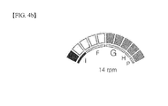
Fig. 4b is an exemplary view showing a user interface (UI) for display of an engine output mode in the case where the operation state of the engine is converted into an idling state in accordance with the present invention. -
- 201: first display control module
- 202: second display control module
- Now, preferred embodiments of the present invention will be described in detail with reference to the accompanying drawings. The matters defined in the description, such as the detailed construction and elements, are nothing but specific details provided to assist those of ordinary skill in the art in a comprehensive understanding of the invention, and the present invention is not limited to the embodiments disclosed hereinafter.
- In order to definitely describe the present invention, a portion having no relevant to the description will be omitted, and through the specification, like elements are designated by like reference numerals.
- In the specification and the claims, when a portion includes an element, it is meant to include other elements, but not exclude the other elements unless otherwise specifically stated herein.
-
Fig. 2 is a block diagram showing the configuration of an engine output display controller in accordance with the present invention. - As shown in
Fig. 2 , the engine output display controller in accordance with the present invention is configured to be connected to a screen display unit and control the screen display unit to display operator setting engine output mode information on a screen thereof. The engine output display controller includes a firstdisplay control module 201 and a second display control module 202. - Herein, the first
display control module 201 outputs first display object information, which enables the operator setting engine output mode information to be distinguished from permissible overall output mode information of a corresponding engine, to the screen display unit if the first display control module senses that an operator setting mode and an engine output mode are different from each other. For example, a distinction between the respective modes is made using a number of bars which have the same shape. Further, when is assumed that the operator setting engine output mode is a five stage engine output mode and the permissible overall output mode of the corresponding engine is a total of ten stage engine output mode, the firstdisplay control module 201 outputs, as first display object information, information regarding the number (e.g., five) of bars which correspond to the five stage engine output mode (i.e., the operator setting engine output mode) and are to be activated, and position information (e.g., information regarding bars ranging from a first bar to a fifth bar in the right direction based on a bar positioned at the left end of the bars) and color information (e.g., colorless) of the bars, as well as information regarding the number (e.g., five) of bars which correspond to the ten stage engine output mode (i.e., the permissible overall output mode of the corresponding engine) and are to be activated, and position information (e.g., information regarding bars ranging from a sixth bar to a tenth bar in the right direction based on a bar positioned at the left end of the bars) and color information (e.g., dark red color) of the bars, to the screen display unit. In this case, matching information among the engine output stage, information regarding the number of the bars which are to be activated and the color information of the bars is previously set and stored in a memory. - The second display control module 202 outputs second display object information, which enables the operator setting engine output mode information to be distinguished from the permissible overall output mode information of the engine and idling state mode information, to the screen display unit if the second display control module, which receives the output mode information requested by the engine and a key signal requested according to an operator's key manipulation, senses that the engine output mode is different from an operator input mode (i.e., if the engine output display controller receives a request for different modes in order for the engine controller to output another mode (e.g., idling mode) but not the operator setting mode to reduce fuel consumption and protect itself, without outputting the engine output mode in the same manner as the operator setting mode depending on the operator setting mode). For example, the second display object information is set such that a distinction between the respective mode information is made by using the bars having the same shape. Further, it is assumed that the operator setting engine output mode is a five stage engine output mode, the permissible overall output mode of the corresponding engine is a total of ten stage engine output mode, and the idling state mode is a one stage engine output mode, the second display control module 204 outputs, as the second display object information, information regarding the number (e.g., five) of bars which correspond to the five stage engine output mode (i.e., the operator setting engine output mode) and are to be activated, and position information (e.g., information regarding bars ranging from a first bar to a fifth bar in the right direction based on a bar positioned at the left end of the bars) and color information (e.g., colorless) of the bars, as well as information regarding the number (e.g., ten) of bars which correspond to the ten stage engine output mode (i.e., the permissible overall output mode of the corresponding engine) and are to be activated, position information (e.g., information regarding bars ranging from a sixth bar to a tenth bar in the right direction based on a bar positioned at the left end of the bars) and color information (e.g., dark red color) of the bars, and information regarding the number (e.g., one) of bars which correspond to the one stage engine output mode (i.e., idling state mode) and are to be activated, and position information (e.g., information regarding a bar positioned at the left end of the bars) and color information (e.g., dark red color) of the bars, to the screen display unit. In this case, matching information among the engine output stage, information regarding the number of the bars which are to be activated and the color information of the bars is previously set and stored in a memory.
-
Fig. 3 is a flowchart sequentially showing the operation of the engine output display controller in accordance with the present invention. - Hereinafter, the operation of the engine output display controller in accordance with the present invention will be described with reference to
Fig. 3 . - As shown in
Fig. 3 , first, the engine output display controller of the present invention generates a first detection signal corresponding to an enable signal if the engine output display controller detects that an operator setting mode and an engine output mode are different from each other (S301). - Therefore, the engine output display controller outputs the first display object information, which enables the operator setting engine output mode information to be distinguished from permissible overall output mode information of a corresponding engine, to the screen display unit, if the first detection signal is generated (i.e., if the engine output display controller detects that the operator setting mode and the engine output mode are different from each other) (S302).
- By virtue of this operation, the operator can previously identify an engine output level before the manipulation of the work apparatus by the operator.
- For example, the first display object information is set such that a distinction between the respective mode information is made by using the bars having the same shape. Further, when it is assumed that the operator setting engine output mode is a five stage engine output mode and the permissible overall output mode of the corresponding engine is a total of ten stage engine output mode, the output operation of the first
display control module 201 will be described hereinafter. - In other words, the engine output display controller outputs, as first display object information, information regarding the number (e.g., five) of bars which correspond to the five stage engine output mode (i.e., the operator setting engine output mode) and are to be activated, and position information (e.g., information regarding bars ranging from a first bar to a fifth bar in the right direction based on a bar positioned at the left end of the bars) and color information (e.g., colorless) of the bars, as well as information regarding the number (e.g., five) of bars which correspond to the ten stage engine output mode (i.e., the permissible overall output mode of the corresponding engine) and are to be activated, and position information (e.g., information regarding bars ranging from a sixth bar to a tenth bar in the right direction based on a bar positioned at the left end of the bars) and color information (e.g., dark red color) of the bars, to the screen display unit. In this case, matching information among the engine output stage, information regarding the number of the bars which are to be activated and the color information of the bars is previously set and stored in a memory.
- Meanwhile, the screen display unit displays the operator setting engine output mode information on a screen thereof such that the operator setting engine output mode information is distinguished from permissible overall output mode information of the corresponding engine based on the first display object information when the screen display unit receives the first display object information from the engine output display controller.
- As a result, the operator can previously identify an engine output level before the manipulation of the work apparatus by the operator.
- In the meantime, the engine output display controller in accordance with the present invention performs a function in which the operator can previously identify an engine output level even in the case where the engine does not work for a predetermined time period and thus the operation state of the engine is converted into the idling state.
- The specific operation thereof will be described hereafter.
- First, the engine output display controller generates a second detection signal corresponding to an enable signal if the engine output display controller, which receives the output mode information requested by the engine and a key signal requested according to an operator's key manipulation, detects that the engine output mode is different from an operator input mode. (S303).
- In other words, the engine output display controller generates a second detection signal corresponding to an enable signal if the engine output display controller receives a request for different modes in order for the engine controller to output another mode (e.g., idling mode) but not the operator setting mode to reduce fuel consumption and protect itself, without outputting the engine output mode in the same manner as the operator setting mode depending on the operator setting mode.
- Subsequently, the engine output display controller outputs the first display object information, which enables the operator setting engine output mode information to be distinguished from permissible overall output mode information of the corresponding engine and the idling state mode information, to the screen display unit, if the second detection signal is generated (i.e., if the engine output display controller detects that the engine output mode is different from the operator input mode) (S304).
- By virtue of this operation, the operator can previously identify an engine output level before the manipulation of the work apparatus, which is in an idling state, by the operator.
- For example, the first display object information is set such that a distinction between the respective mode information is made by using the bars having the same shape. Further, when it is assumed that the operator setting engine output mode is a five stage engine output mode, the permissible overall output mode of the corresponding engine is a total of ten stage engine output mode, and the idling state mode is a one engine output mode, the output operation of the engine output display controller will be described hereinafter.
- In this words, the engine output display controller outputs, as the second display object information, information regarding the number (e.g., five) of bars which correspond to the five stage engine output mode (i.e., the operator setting engine output mode) and are to be activated, and position information (e.g., information regarding bars ranging from a first bar to a fifth bar in the right direction based on a bar positioned at the left end of the bars) and color information (e.g., colorless) of the bars, as well as information regarding the number (e.g., ten) of bars which correspond to the ten stage engine output mode (i.e., the permissible overall output mode of the corresponding engine) and are to be activated, position information (e.g., information regarding bars ranging from a sixth bar to a tenth bar in the right direction based on a bar positioned at the left end of the bars) and color information (e.g., dark red color) of the bars, and information regarding the number (e.g., one) of bars which correspond to the one stage engine output mode (i.e., idling state mode) and are to be activated, and position information (e.g., information regarding a bar positioned at the left end of the bars) and color information (e.g., dark red color) of the bars, to the screen display unit.
- In this case, matching information among the engine output stage, information regarding the number of the bars which are to be activated and the color information of the bars is previously set and stored in a memory.
- Meanwhile, the screen display unit displays the operator setting engine output mode information on the screen thereof such that the operator setting engine output mode information is distinguished from permissible overall output mode information of the corresponding engine and the idling state mode information based on the second display object information when the screen display unit receives the second display object information from the engine output display controller.
- As a result, the operator can previously identify an engine output level before the manipulation of the work apparatus, which is in an idling state, by the operator.
- As described above, the engine output display controller of the present invention can control the engine output mode information set by the operator to be displayed on the screen before the operator operates a work apparatus so that the operator setting engine output mode information is distinguished from the permissible overall output mode information of the engine and the idling state mode information to allow the operator to previously identify an engine output level before the manipulation of the work apparatus by the operator.
-
Figs. 4a and4b are exemplary views showing a user interface (UI) for display of an engine output mode of the engine output display controller in accordance with the present invention. - More specifically,
Fig. 4a is an exemplary view showing a user interface (UI) for display of an engine output mode in a start key-on state before the startup of an engine in accordance with the present invention, andFig. 4b is an exemplary view showing a user interface (UI) for display of an engine output mode in the case where the operation state of the engine is converted into an idling state due to non-manipulation of the work apparatus by the operator in accordance with the present invention. - The example of the user interface (UI) is an example set such that a distinction between the respective mode information is made using a number of bars which have the same shape.
- In addition, the example of the user interface (UI) is an example for the case where it is assumed that the operator setting engine output mode is a five stage engine output mode, the permissible overall output mode of the corresponding engine is a total of ten stage engine output mode, and the idling state mode is a one engine output mode.
- As shown in
Fig. 4a , in the case of a start key-on state before the startup of the engine, the operator setting engine output mode (five stage) information is displayed on the screen of the screen display unit such that the operator setting engine output mode information is distinguished from permissible overall output mode information of the corresponding engine. - In other words, the five stage engine output mode information corresponding to the operator setting engine output mode is displayed on the screen such that information regarding bars ranging from a first bar to a fifth bar in the right direction based on a bar positioned at the left end of the bars is displayed in a colorless pattern. The permissible overall output mode of the corresponding engine, which corresponds to the ten stage engine output mode information, is displayed on the screen such that information regarding bars ranging from a sixth bar to a tenth bar in the right direction based on a bar positioned at the left end of the bars is displayed in a dark red color, so that the operator setting engine output mode (five stage) information is distinguished from the permissible overall output mode of the corresponding engine.
- By virtue of this operation, the operator can previously identify an engine output level (e.g., five stage) before the manipulation of the work apparatus by the operator.
- On the other hand, as shown in
Fig. 4b , the engine output display controller in accordance with the present invention performs a function in which the operator can previously identify an engine output level even in the case where the engine does not work for a predetermined time period and thus the operation state of the engine is converted into the idling state. - In other words, as shown in
Fig. 4b , in the case where the engine does not work for a predetermined time period and thus the operation state of the engine is converted into the idling state, the operator setting engine output mode (five stage) information is displayed on the screen by the engine output display controller such that the operator setting engine output mode (five stage) information is distinguished from the permissible overall output mode of the corresponding engine and the idling state mode(one stage). - Specifically, the five stage engine output mode information corresponding to the operator setting engine output mode is displayed on the screen such that information regarding bars ranging from a second bar to a fifth bar in the right direction based on a bar positioned at the left end of the bars is displayed in a colorless pattern. The ten stage engine output mode information, which corresponds to the permissible overall output mode of the corresponding engine, is displayed on the screen such that information regarding bars ranging from a sixth bar to a tenth bar in the right direction based on a bar positioned at the left end of the bars is displayed in a dark red color. In addition, the one stage engine output mode information corresponding to the idling state mode is displayed on the screen such that a bar positioned at the left end of the bars is displayed in a dark red color to enable the operator setting engine output mode (five stage) information to be distinguished from the permissible overall output mode (ten stage) of the corresponding engine and the idling state mode (one stage).
- By virtue of this operation, the operator can previously identify an engine output level (e.g., five stage in the above example) before the manipulation of the work apparatus, which is in an idling state, by the operator.
- In accordance with the engine output display controller and the method for displaying an engine output mode thereof of the present invention as constructed above, the engine output mode information set by the operator is controlled to be displayed on the screen before the operator operates a work apparatus so that the operator setting engine output mode information is distinguished from the permissible overall output mode information of the engine and the idling state mode information to allow the operator to previously identify an engine output level before the manipulation of the work apparatus by the operator.
- While the present invention has been described in connection with the specific embodiments illustrated in the drawings, they are merely illustrative, and the invention is not limited to these embodiments. It is to be understood that various equivalent modifications and variations of the embodiments can be made by a person having an ordinary skill in the art without departing from the spirit and scope of the present invention. Therefore, the true technical scope of the present invention should not be defined by the above-mentioned embodiments but should be defined by the appended claims and equivalents thereof.
Claims (6)
- A method for displaying an engine output mode of an engine output display controller connected to a screen display unit, the method comprising a step of controlling the screen display unit to display operator setting engine output mode information on a screen thereof,
wherein the controlling step controls the display operation of the screen display unit so that the operator setting engine output mode information is distinguished from permissible overall output mode information of a corresponding engine if the engine output display controller senses that an operator setting mode and an engine output mode are different from each other. - The method for displaying an engine output mode according to claim 1, wherein the controlling step controls the display operation of the screen display unit so that the operator setting engine output mode information is distinguished from the permissible overall output mode information of the engine and idling state mode information if the engine output display controller, which receives the output mode information requested by the engine and a key signal requested according to an operator's key manipulation, senses that the engine output mode is different from an operator input mode.
- The method for displaying an engine output mode according to claim 1 or 2, wherein the engine output display controller makes a distinction between the respective modes using information regarding the number of bars which have the same shape and are differently activated for the respective modes, and position information and color information of the bars.
- An engine output display controller connected to a screen display unit and configured to control the screen display unit to display operator setting engine output mode information on a screen thereof, the controller comprising:a first display control module configured to output first display object information, which enables the operator setting engine output mode information to be distinguished from permissible overall output mode information of a corresponding engine, to the screen display unit if the first display control module senses that an operator setting mode and an engine output mode are different from each other.
- The engine output display controller according to claim 4, further comprising a second display control module configured to output second display object information, which enables the operator setting engine output mode information to be distinguished from the permissible overall output mode information of the engine and idling state mode information, to the screen display unit if the second display control module, which receives the output mode information requested by the engine and a key signal requested according to an operator's key manipulation, senses that the engine output mode is different from an operator input mode.
- The engine output display controller according to claim 4 or 5, wherein a distinction between the respective modes is made using information, regarding the number of bars which have the same shape and are differently activated for the respective modes, and position information and color information of the bars.
Applications Claiming Priority (1)
| Application Number | Priority Date | Filing Date | Title |
|---|---|---|---|
| PCT/KR2012/011249 WO2014098286A1 (en) | 2012-12-21 | 2012-12-21 | Engine output display controller and method for displaying engine output mode thereof |
Publications (2)
| Publication Number | Publication Date |
|---|---|
| EP2937546A1 true EP2937546A1 (en) | 2015-10-28 |
| EP2937546A4 EP2937546A4 (en) | 2017-04-12 |
Family
ID=50978581
Family Applications (1)
| Application Number | Title | Priority Date | Filing Date |
|---|---|---|---|
| EP12890621.1A Withdrawn EP2937546A4 (en) | 2012-12-21 | 2012-12-21 | Engine output display controller and method for displaying engine output mode thereof |
Country Status (6)
| Country | Link |
|---|---|
| US (1) | US20150328988A1 (en) |
| EP (1) | EP2937546A4 (en) |
| KR (1) | KR20150097541A (en) |
| CN (1) | CN104870791A (en) |
| CA (1) | CA2895047A1 (en) |
| WO (1) | WO2014098286A1 (en) |
Families Citing this family (2)
| Publication number | Priority date | Publication date | Assignee | Title |
|---|---|---|---|---|
| JPWO2022210662A1 (en) * | 2021-03-31 | 2022-10-06 | ||
| CN113152550B (en) * | 2021-04-07 | 2022-12-20 | 柳州柳工挖掘机有限公司 | Operation mode control system and method and excavator |
Family Cites Families (11)
| Publication number | Priority date | Publication date | Assignee | Title |
|---|---|---|---|---|
| US5376917A (en) * | 1991-08-19 | 1994-12-27 | Mitsubishi Jidosha Kogyo Kabushiki Kaisha | Vehicle display apparatus with drive information |
| US6625562B2 (en) * | 2001-10-12 | 2003-09-23 | Coato Workshop, Inc. | Multiple rpm indicating tachometer for motor vehicles |
| KR200301545Y1 (en) * | 2002-10-10 | 2003-01-24 | 김용순 | The engine instrument board of digital system |
| JP4506286B2 (en) * | 2003-08-19 | 2010-07-21 | 株式会社小松製作所 | Construction machinery |
| WO2009038502A1 (en) * | 2007-09-17 | 2009-03-26 | Volvo Technology Corporation | Method for communicating a deviation of a vehicle parameter |
| DE102008064023A1 (en) * | 2008-12-19 | 2009-09-17 | Daimler Ag | Current operating point displaying method for motor vehicle, involves representing current operating point on display unit in connection with engine efficiency ranges that are represented differently according to corresponding evaluation |
| KR20100084848A (en) * | 2009-01-19 | 2010-07-28 | 볼보 컨스트럭션 이키프먼트 홀딩 스웨덴 에이비 | Engine rpm control system for an excavator |
| CN201614977U (en) * | 2009-12-14 | 2010-10-27 | 上海三一科技有限公司 | Crane engine throttle control device |
| KR101738686B1 (en) * | 2010-12-23 | 2017-05-23 | 두산인프라코어 주식회사 | an attachment control method for a construction heavy equipment |
| JP5357197B2 (en) * | 2011-02-02 | 2013-12-04 | 株式会社日本除雪機製作所 | Monitoring system for rotary snow plow and rotary snow plow |
| JP5562285B2 (en) * | 2011-04-15 | 2014-07-30 | 日立建機株式会社 | Work machine display |
-
2012
- 2012-12-21 KR KR1020157016393A patent/KR20150097541A/en not_active Abandoned
- 2012-12-21 WO PCT/KR2012/011249 patent/WO2014098286A1/en not_active Ceased
- 2012-12-21 US US14/653,738 patent/US20150328988A1/en not_active Abandoned
- 2012-12-21 EP EP12890621.1A patent/EP2937546A4/en not_active Withdrawn
- 2012-12-21 CA CA2895047A patent/CA2895047A1/en not_active Abandoned
- 2012-12-21 CN CN201280077905.8A patent/CN104870791A/en active Pending
Non-Patent Citations (1)
| Title |
|---|
| See references of WO2014098286A1 * |
Also Published As
| Publication number | Publication date |
|---|---|
| WO2014098286A1 (en) | 2014-06-26 |
| CN104870791A (en) | 2015-08-26 |
| CA2895047A1 (en) | 2014-06-26 |
| KR20150097541A (en) | 2015-08-26 |
| US20150328988A1 (en) | 2015-11-19 |
| EP2937546A4 (en) | 2017-04-12 |
Similar Documents
| Publication | Publication Date | Title |
|---|---|---|
| US20220214683A1 (en) | Program for operating vehicle from outside vehicle | |
| WO2011010396A1 (en) | Remote control system for machine tool | |
| US20160313968A1 (en) | Display system, display appararus and adjustment method | |
| JP2015013739A (en) | Input-output interface device for elevator control signal | |
| KR101748724B1 (en) | Apparatus for testing valve base electronics | |
| US20150328988A1 (en) | Engine output display controller and method for displaying engine output mode thereof | |
| JP2019205093A (en) | Sensor coordination facility system | |
| JP6816765B2 (en) | Vehicle display device | |
| US11133628B2 (en) | Power strip with device information input and display capabilities | |
| CN101334740B (en) | External progress processing method and processing unit | |
| US10620823B2 (en) | Information processing device and displaying method for switching between faceplates for controlling field devices | |
| JP5155765B2 (en) | Communications system | |
| JP2020013196A5 (en) | ||
| JP2009258983A (en) | System for remote maintenance of machine tool using the internet connection | |
| KR20140002662A (en) | Code lock system for preventing theft and method thereof | |
| US20150302824A1 (en) | Display device and color calibration method | |
| JP2016146112A5 (en) | ||
| JP2010118766A (en) | Communicating system and diagnosis method thereof | |
| US20210182368A1 (en) | Robot operation terminal | |
| JP4869559B2 (en) | Image signal generator, image display device, and on-line control method of image display device | |
| US9172932B2 (en) | Video signal paths switching in a portable display system | |
| WO2014061203A1 (en) | Information processing terminal | |
| EP2937256A1 (en) | Method for controlling vehicle-information displaying by means of ecu and apparatus therefor | |
| JP2007272827A (en) | Sensor system and sensor unit | |
| EP2792799A1 (en) | Good-efficiency rpm zone display device for construction machinery |
Legal Events
| Date | Code | Title | Description |
|---|---|---|---|
| PUAI | Public reference made under article 153(3) epc to a published international application that has entered the european phase |
Free format text: ORIGINAL CODE: 0009012 |
|
| 17P | Request for examination filed |
Effective date: 20150612 |
|
| AK | Designated contracting states |
Kind code of ref document: A1 Designated state(s): AL AT BE BG CH CY CZ DE DK EE ES FI FR GB GR HR HU IE IS IT LI LT LU LV MC MK MT NL NO PL PT RO RS SE SI SK SM TR |
|
| AX | Request for extension of the european patent |
Extension state: BA ME |
|
| RIN1 | Information on inventor provided before grant (corrected) |
Inventor name: KIM, JI-EUN Inventor name: LEE, MYUNG-HOON |
|
| DAX | Request for extension of the european patent (deleted) | ||
| A4 | Supplementary search report drawn up and despatched |
Effective date: 20170315 |
|
| RIC1 | Information provided on ipc code assigned before grant |
Ipc: F02D 29/00 20060101ALI20170309BHEP Ipc: F02D 45/00 20060101AFI20170309BHEP Ipc: B60K 35/00 20060101ALI20170309BHEP Ipc: B60K 37/02 20060101ALI20170309BHEP Ipc: F02D 41/24 20060101ALI20170309BHEP Ipc: E02F 9/26 20060101ALI20170309BHEP |
|
| STAA | Information on the status of an ep patent application or granted ep patent |
Free format text: STATUS: THE APPLICATION IS DEEMED TO BE WITHDRAWN |
|
| 18D | Application deemed to be withdrawn |
Effective date: 20171011 |