EP2937405B1 - Integriertes trocknungs- und vergasungsverfahren zur gleichzeitigen herstellung von synthesegas und kohle mit hohem inkohlungsgrad - Google Patents
Integriertes trocknungs- und vergasungsverfahren zur gleichzeitigen herstellung von synthesegas und kohle mit hohem inkohlungsgrad Download PDFInfo
- Publication number
- EP2937405B1 EP2937405B1 EP13866242.4A EP13866242A EP2937405B1 EP 2937405 B1 EP2937405 B1 EP 2937405B1 EP 13866242 A EP13866242 A EP 13866242A EP 2937405 B1 EP2937405 B1 EP 2937405B1
- Authority
- EP
- European Patent Office
- Prior art keywords
- coal
- dryer
- synthesis gas
- gasifier
- water
- Prior art date
- Legal status (The legal status is an assumption and is not a legal conclusion. Google has not performed a legal analysis and makes no representation as to the accuracy of the status listed.)
- Active
Links
Images

Classifications
-
- C—CHEMISTRY; METALLURGY
- C10—PETROLEUM, GAS OR COKE INDUSTRIES; TECHNICAL GASES CONTAINING CARBON MONOXIDE; FUELS; LUBRICANTS; PEAT
- C10J—PRODUCTION OF PRODUCER GAS, WATER-GAS, SYNTHESIS GAS FROM SOLID CARBONACEOUS MATERIAL, OR MIXTURES CONTAINING THESE GASES; CARBURETTING AIR OR OTHER GASES
- C10J3/00—Production of combustible gases containing carbon monoxide from solid carbonaceous fuels
-
- C—CHEMISTRY; METALLURGY
- C10—PETROLEUM, GAS OR COKE INDUSTRIES; TECHNICAL GASES CONTAINING CARBON MONOXIDE; FUELS; LUBRICANTS; PEAT
- C10J—PRODUCTION OF PRODUCER GAS, WATER-GAS, SYNTHESIS GAS FROM SOLID CARBONACEOUS MATERIAL, OR MIXTURES CONTAINING THESE GASES; CARBURETTING AIR OR OTHER GASES
- C10J3/00—Production of combustible gases containing carbon monoxide from solid carbonaceous fuels
- C10J3/46—Gasification of granular or pulverulent flues in suspension
- C10J3/466—Entrained flow processes
-
- C—CHEMISTRY; METALLURGY
- C10—PETROLEUM, GAS OR COKE INDUSTRIES; TECHNICAL GASES CONTAINING CARBON MONOXIDE; FUELS; LUBRICANTS; PEAT
- C10J—PRODUCTION OF PRODUCER GAS, WATER-GAS, SYNTHESIS GAS FROM SOLID CARBONACEOUS MATERIAL, OR MIXTURES CONTAINING THESE GASES; CARBURETTING AIR OR OTHER GASES
- C10J3/00—Production of combustible gases containing carbon monoxide from solid carbonaceous fuels
- C10J3/46—Gasification of granular or pulverulent flues in suspension
- C10J3/48—Apparatus; Plants
- C10J3/485—Entrained flow gasifiers
-
- C—CHEMISTRY; METALLURGY
- C10—PETROLEUM, GAS OR COKE INDUSTRIES; TECHNICAL GASES CONTAINING CARBON MONOXIDE; FUELS; LUBRICANTS; PEAT
- C10J—PRODUCTION OF PRODUCER GAS, WATER-GAS, SYNTHESIS GAS FROM SOLID CARBONACEOUS MATERIAL, OR MIXTURES CONTAINING THESE GASES; CARBURETTING AIR OR OTHER GASES
- C10J3/00—Production of combustible gases containing carbon monoxide from solid carbonaceous fuels
- C10J3/72—Other features
- C10J3/82—Gas withdrawal means
- C10J3/84—Gas withdrawal means with means for removing dust or tar from the gas
-
- C—CHEMISTRY; METALLURGY
- C10—PETROLEUM, GAS OR COKE INDUSTRIES; TECHNICAL GASES CONTAINING CARBON MONOXIDE; FUELS; LUBRICANTS; PEAT
- C10L—FUELS NOT OTHERWISE PROVIDED FOR; NATURAL GAS; SYNTHETIC NATURAL GAS OBTAINED BY PROCESSES NOT COVERED BY SUBCLASSES C10G OR C10K; LIQUIFIED PETROLEUM GAS; USE OF ADDITIVES TO FUELS OR FIRES; FIRE-LIGHTERS
- C10L5/00—Solid fuels
- C10L5/02—Solid fuels such as briquettes consisting mainly of carbonaceous materials of mineral or non-mineral origin
-
- C—CHEMISTRY; METALLURGY
- C10—PETROLEUM, GAS OR COKE INDUSTRIES; TECHNICAL GASES CONTAINING CARBON MONOXIDE; FUELS; LUBRICANTS; PEAT
- C10L—FUELS NOT OTHERWISE PROVIDED FOR; NATURAL GAS; SYNTHETIC NATURAL GAS OBTAINED BY PROCESSES NOT COVERED BY SUBCLASSES C10G OR C10K; LIQUIFIED PETROLEUM GAS; USE OF ADDITIVES TO FUELS OR FIRES; FIRE-LIGHTERS
- C10L5/00—Solid fuels
- C10L5/02—Solid fuels such as briquettes consisting mainly of carbonaceous materials of mineral or non-mineral origin
- C10L5/04—Raw material of mineral origin to be used; Pretreatment thereof
-
- C—CHEMISTRY; METALLURGY
- C10—PETROLEUM, GAS OR COKE INDUSTRIES; TECHNICAL GASES CONTAINING CARBON MONOXIDE; FUELS; LUBRICANTS; PEAT
- C10L—FUELS NOT OTHERWISE PROVIDED FOR; NATURAL GAS; SYNTHETIC NATURAL GAS OBTAINED BY PROCESSES NOT COVERED BY SUBCLASSES C10G OR C10K; LIQUIFIED PETROLEUM GAS; USE OF ADDITIVES TO FUELS OR FIRES; FIRE-LIGHTERS
- C10L5/00—Solid fuels
- C10L5/02—Solid fuels such as briquettes consisting mainly of carbonaceous materials of mineral or non-mineral origin
- C10L5/06—Methods of shaping, e.g. pelletizing or briquetting
- C10L5/08—Methods of shaping, e.g. pelletizing or briquetting without the aid of extraneous binders
-
- C—CHEMISTRY; METALLURGY
- C10—PETROLEUM, GAS OR COKE INDUSTRIES; TECHNICAL GASES CONTAINING CARBON MONOXIDE; FUELS; LUBRICANTS; PEAT
- C10L—FUELS NOT OTHERWISE PROVIDED FOR; NATURAL GAS; SYNTHETIC NATURAL GAS OBTAINED BY PROCESSES NOT COVERED BY SUBCLASSES C10G OR C10K; LIQUIFIED PETROLEUM GAS; USE OF ADDITIVES TO FUELS OR FIRES; FIRE-LIGHTERS
- C10L5/00—Solid fuels
- C10L5/02—Solid fuels such as briquettes consisting mainly of carbonaceous materials of mineral or non-mineral origin
- C10L5/34—Other details of the shaped fuels, e.g. briquettes
- C10L5/36—Shape
- C10L5/361—Briquettes
-
- C—CHEMISTRY; METALLURGY
- C10—PETROLEUM, GAS OR COKE INDUSTRIES; TECHNICAL GASES CONTAINING CARBON MONOXIDE; FUELS; LUBRICANTS; PEAT
- C10L—FUELS NOT OTHERWISE PROVIDED FOR; NATURAL GAS; SYNTHETIC NATURAL GAS OBTAINED BY PROCESSES NOT COVERED BY SUBCLASSES C10G OR C10K; LIQUIFIED PETROLEUM GAS; USE OF ADDITIVES TO FUELS OR FIRES; FIRE-LIGHTERS
- C10L5/00—Solid fuels
- C10L5/02—Solid fuels such as briquettes consisting mainly of carbonaceous materials of mineral or non-mineral origin
- C10L5/34—Other details of the shaped fuels, e.g. briquettes
- C10L5/36—Shape
- C10L5/363—Pellets or granulates
-
- C—CHEMISTRY; METALLURGY
- C10—PETROLEUM, GAS OR COKE INDUSTRIES; TECHNICAL GASES CONTAINING CARBON MONOXIDE; FUELS; LUBRICANTS; PEAT
- C10L—FUELS NOT OTHERWISE PROVIDED FOR; NATURAL GAS; SYNTHETIC NATURAL GAS OBTAINED BY PROCESSES NOT COVERED BY SUBCLASSES C10G OR C10K; LIQUIFIED PETROLEUM GAS; USE OF ADDITIVES TO FUELS OR FIRES; FIRE-LIGHTERS
- C10L9/00—Treating solid fuels to improve their combustion
- C10L9/08—Treating solid fuels to improve their combustion by heat treatments, e.g. calcining
-
- F—MECHANICAL ENGINEERING; LIGHTING; HEATING; WEAPONS; BLASTING
- F26—DRYING
- F26B—DRYING SOLID MATERIALS OR OBJECTS BY REMOVING LIQUID THEREFROM
- F26B17/00—Machines or apparatus for drying materials in loose, plastic, or fluidised form, e.g. granules, staple fibres, with progressive movement
- F26B17/10—Machines or apparatus for drying materials in loose, plastic, or fluidised form, e.g. granules, staple fibres, with progressive movement with movement performed by fluid currents, e.g. issuing from a nozzle, e.g. pneumatic, flash, vortex or entrainment dryers
- F26B17/101—Machines or apparatus for drying materials in loose, plastic, or fluidised form, e.g. granules, staple fibres, with progressive movement with movement performed by fluid currents, e.g. issuing from a nozzle, e.g. pneumatic, flash, vortex or entrainment dryers the drying enclosure having the shape of one or a plurality of shafts or ducts, e.g. with substantially straight and vertical axis
- F26B17/102—Machines or apparatus for drying materials in loose, plastic, or fluidised form, e.g. granules, staple fibres, with progressive movement with movement performed by fluid currents, e.g. issuing from a nozzle, e.g. pneumatic, flash, vortex or entrainment dryers the drying enclosure having the shape of one or a plurality of shafts or ducts, e.g. with substantially straight and vertical axis with material recirculation, classifying or disintegrating means
-
- C—CHEMISTRY; METALLURGY
- C10—PETROLEUM, GAS OR COKE INDUSTRIES; TECHNICAL GASES CONTAINING CARBON MONOXIDE; FUELS; LUBRICANTS; PEAT
- C10J—PRODUCTION OF PRODUCER GAS, WATER-GAS, SYNTHESIS GAS FROM SOLID CARBONACEOUS MATERIAL, OR MIXTURES CONTAINING THESE GASES; CARBURETTING AIR OR OTHER GASES
- C10J2200/00—Details of gasification apparatus
- C10J2200/15—Details of feeding means
-
- C—CHEMISTRY; METALLURGY
- C10—PETROLEUM, GAS OR COKE INDUSTRIES; TECHNICAL GASES CONTAINING CARBON MONOXIDE; FUELS; LUBRICANTS; PEAT
- C10J—PRODUCTION OF PRODUCER GAS, WATER-GAS, SYNTHESIS GAS FROM SOLID CARBONACEOUS MATERIAL, OR MIXTURES CONTAINING THESE GASES; CARBURETTING AIR OR OTHER GASES
- C10J2300/00—Details of gasification processes
- C10J2300/09—Details of the feed, e.g. feeding of spent catalyst, inert gas or halogens
- C10J2300/0903—Feed preparation
- C10J2300/0909—Drying
-
- C—CHEMISTRY; METALLURGY
- C10—PETROLEUM, GAS OR COKE INDUSTRIES; TECHNICAL GASES CONTAINING CARBON MONOXIDE; FUELS; LUBRICANTS; PEAT
- C10J—PRODUCTION OF PRODUCER GAS, WATER-GAS, SYNTHESIS GAS FROM SOLID CARBONACEOUS MATERIAL, OR MIXTURES CONTAINING THESE GASES; CARBURETTING AIR OR OTHER GASES
- C10J2300/00—Details of gasification processes
- C10J2300/09—Details of the feed, e.g. feeding of spent catalyst, inert gas or halogens
- C10J2300/0913—Carbonaceous raw material
- C10J2300/093—Coal
-
- C—CHEMISTRY; METALLURGY
- C10—PETROLEUM, GAS OR COKE INDUSTRIES; TECHNICAL GASES CONTAINING CARBON MONOXIDE; FUELS; LUBRICANTS; PEAT
- C10J—PRODUCTION OF PRODUCER GAS, WATER-GAS, SYNTHESIS GAS FROM SOLID CARBONACEOUS MATERIAL, OR MIXTURES CONTAINING THESE GASES; CARBURETTING AIR OR OTHER GASES
- C10J2300/00—Details of gasification processes
- C10J2300/18—Details of the gasification process, e.g. loops, autothermal operation
- C10J2300/1861—Heat exchange between at least two process streams
-
- C—CHEMISTRY; METALLURGY
- C10—PETROLEUM, GAS OR COKE INDUSTRIES; TECHNICAL GASES CONTAINING CARBON MONOXIDE; FUELS; LUBRICANTS; PEAT
- C10J—PRODUCTION OF PRODUCER GAS, WATER-GAS, SYNTHESIS GAS FROM SOLID CARBONACEOUS MATERIAL, OR MIXTURES CONTAINING THESE GASES; CARBURETTING AIR OR OTHER GASES
- C10J3/00—Production of combustible gases containing carbon monoxide from solid carbonaceous fuels
- C10J3/46—Gasification of granular or pulverulent flues in suspension
- C10J3/48—Apparatus; Plants
-
- C—CHEMISTRY; METALLURGY
- C10—PETROLEUM, GAS OR COKE INDUSTRIES; TECHNICAL GASES CONTAINING CARBON MONOXIDE; FUELS; LUBRICANTS; PEAT
- C10L—FUELS NOT OTHERWISE PROVIDED FOR; NATURAL GAS; SYNTHETIC NATURAL GAS OBTAINED BY PROCESSES NOT COVERED BY SUBCLASSES C10G OR C10K; LIQUIFIED PETROLEUM GAS; USE OF ADDITIVES TO FUELS OR FIRES; FIRE-LIGHTERS
- C10L2290/00—Fuel preparation or upgrading, processes or apparatus therefore, comprising specific process steps or apparatus units
- C10L2290/06—Heat exchange, direct or indirect
-
- C—CHEMISTRY; METALLURGY
- C10—PETROLEUM, GAS OR COKE INDUSTRIES; TECHNICAL GASES CONTAINING CARBON MONOXIDE; FUELS; LUBRICANTS; PEAT
- C10L—FUELS NOT OTHERWISE PROVIDED FOR; NATURAL GAS; SYNTHETIC NATURAL GAS OBTAINED BY PROCESSES NOT COVERED BY SUBCLASSES C10G OR C10K; LIQUIFIED PETROLEUM GAS; USE OF ADDITIVES TO FUELS OR FIRES; FIRE-LIGHTERS
- C10L2290/00—Fuel preparation or upgrading, processes or apparatus therefore, comprising specific process steps or apparatus units
- C10L2290/08—Drying or removing water
-
- Y—GENERAL TAGGING OF NEW TECHNOLOGICAL DEVELOPMENTS; GENERAL TAGGING OF CROSS-SECTIONAL TECHNOLOGIES SPANNING OVER SEVERAL SECTIONS OF THE IPC; TECHNICAL SUBJECTS COVERED BY FORMER USPC CROSS-REFERENCE ART COLLECTIONS [XRACs] AND DIGESTS
- Y02—TECHNOLOGIES OR APPLICATIONS FOR MITIGATION OR ADAPTATION AGAINST CLIMATE CHANGE
- Y02E—REDUCTION OF GREENHOUSE GAS [GHG] EMISSIONS, RELATED TO ENERGY GENERATION, TRANSMISSION OR DISTRIBUTION
- Y02E20/00—Combustion technologies with mitigation potential
- Y02E20/16—Combined cycle power plant [CCPP], or combined cycle gas turbine [CCGT]
- Y02E20/18—Integrated gasification combined cycle [IGCC], e.g. combined with carbon capture and storage [CCS]
Definitions
- the present invention relates to a gasification process for co-producing synthesis gas and high-grade (high-quality) coal from water-containing coal. More particularly, the present invention relates to a gasification process in which a dryer for drying water-containing coal (feedstock) using the heat of synthesis gas is disposed in front of a gasifier, whereby dried coal can be easily transferred to the gasifier by a non-mechanical valve-type transfer means, and synthesis gas and high-quality coal containing a very small amount of water can be co-produced, and to an integrated drying and gasification system for realizing the same.
- a gasification process is a series of processes for converting a carbonaceous feedstock such as coal, biomass or the like into synthesis gas containing hydrogen and carbon monoxide as major components using a gasification reaction under the supply of a gasifying agent (for example, oxygen, steam, carbon dioxide or a mixture thereof).
- a gasifying agent for example, oxygen, steam, carbon dioxide or a mixture thereof.
- synthesis gas generally means a gas mixture including CO and H 2 .
- Examples of typical reaction mechanisms of such a gasification process are represented by the following Reaction Formulae 1 to 3.
- Reaction Formula 1 C+1/2O 2 ⁇ CO (partial oxidation)
- reaction Formula 3 C + CO 2 ⁇ 2CO (carbon dioxide reforming)
- a gasification process has been diversified into various kinds of technologies for producing various compounds, and application fields thereof have spread in order to produce various products including electric power.
- a gasification process can be applied to power generation, ammonia preparation, oil refining and the like using hydrogen and carbon monoxide included in synthesis gas which is a main product of a gasification process; that it can be used to produce diesel oil, jet oil, lubricant base oil, naphtha and the like using synthesis gas as a feedstock of Fischer-Tropsch reaction represented by the following Reaction Formula 4; and that it can be used to produce high value-added chemical materials such as acetic acid, olefin, dimethyl ether, aldehyde, fuel, additives and the like using methanol prepared from synthesis gas as represented by the following Reaction Formula 5.
- the ratio of carbon monoxide to hydrogen be about 1: 2.
- reaction Formula 5 CO + 2H 2 ⁇ CH 3 OH
- the ratio of carbon monoxide to hydrogen does not reach 1: 2. Therefore, generally, the ratio of carbon monoxide to hydrogen may be adjusted to about 1: 2 by performing the water-gas-shift reaction of a reaction product obtained after a steam reforming reaction, a partial oxidation reaction and/or a carbon monoxide reforming reaction or by additionally supplying hydrogen to the reaction product.
- reaction Formula 6 CO + H 2 O ⁇ CO 2 + H 2
- coal which a typical feedstock in a gasification process
- biomass which has recently attracted attention, can also be converted into a basic fraction of various kinds of fuels and platform compounds by various treatment processes, there is a known technology of applying biomass as a feedstock in a gasification reaction.
- the above-mentioned feedstock in a gasification process contains a large amount of water.
- coals are classified into high-grade coal and low-grade coal depending on the properties thereof, such as heating value, water content, impurities, etc.
- the amount of low-grade coal (brown coal, etc.) reserves occupies about 45% of the total amount of coal reserves throughout the world.
- the content of water in coal is high, the coal becomes poor in terms of storability, treatability, freight and the like, so a large amount of energy is consumed to remove water from the coal prior to a gasification reaction.
- U.S. Patent Nos. 5,695,532 and 5,685,138 disclose technologies for using the heat of synthesis gas to dry a water-containing carbonaceous feedstock by disposing a dryer in front of a gasification reactor and recycling the high-temperature synthesis gas generated from the gasification reactor into the dryer.
- synthesis gas is discharged from a gasifier at high temperature (1000 to 1500 °C), whereas synthesis gas having relatively low temperature (about 500 °C) may also be used in order to dry water-containing coal.
- a heat exchanger is disposed behind a gasifier to decrease the temperature of the feedstock to the temperature of synthesis gas, and then the feedstock is recycled or is cooled to a temperature suitable for subsequent processes (for example, water-gas-shift reaction).
- solid fuel dried by dryer particularly, dried coal has higher quality than water-containing coal. Therefore, if such high-quality solid fuel (that is, dried coal) can be produced such that it is used as a feedstock for a gasification reaction as well as is applied to other uses, the added value in the total process will be increased.
- high-quality solid fuel that is, dried coal
- the pressurization system including a buffer bin and a pressure lock hopper, it is inevitable that the size of equipment increases, and thus equipment investment cost and operation cost increase.
- WO 2012/151625 describes a gasification apparatus and process comprising a gasifier and a coal drying system, wherein the produced synthesis gas from the gasifier passes through a cyclone and is recycled as fluidization gas for the coal drying. After the drying step, the synthesis gas is separated from the solids in a gas/solid separation device, stored in a vessel and fed to the gasifier by means of a "feed leg". The temperature of the recycled gas lies anywhere between 750-1600°, more specifically between 750-1050°C.
- WO 2010/141930 shows an example of such a loop seal having numerous ports for aeration gas.
- the seal is used for returning solid material from a separation device to the gasifier.
- an object of the present invention is to overcome the conventional problem of utilizing the thermal energy of synthesis gas produced by a gasification reaction only to dry a feedstock in a dryer disposed in front of a gasification reactor by recycling the synthesis gas, thereby providing additional advantages.
- a first aspect of the present invention provides a gasification method of co-producing synthesis gas and high-quality coal, including the steps of a) supplying water-containing coal to a dryer; b) drying the water-containing coal in the dryer, in which thermal energy necessary for drying the water-containing coal is supplied in contact with synthesis gas recycled to the dryer from a gasification step; c) separating dried coal and synthesis gas discharged from the dryer using solid-gas separation and then recovering the separated synthesis gas; d) recovering a part of the separated dried coal and simultaneously transferring the residual separated dried coal to a gasifier in a fluidic state using a loop seal type transfer means to which aeration gas is supplied by a plurality of ports; e) gasifying the transferred dried coal in the gasifier to prepare synthesis gas; and f) directly recycling the synthesis gas of 400 to 1500 °C discharged from the gasifier without passing the synthesis gas through a heat exchanger, wherein the dryer provides a drying capacity necessary for producing the dried coal separated
- the gasification method may further include the step of separating and recovering tar generated in the step of drying the water-containing coal and included in the synthesis gas in the step c) of recovering the synthesis gas.
- a second aspect of the present invention provides an integrated drying and gasification system, including: a gasifier; a dryer disposed in front of the gasifier to dry water-containing coal in contact with synthesis gas recycled from the gasifier and then discharge dried coal and synthesis gas; a solid-gas separator for separating the dried coal and synthesis gas discharged from the dryer; a recovery unit for separating and recovering a part of the dried coal separated by the solid-gas separator; and a loop seal type transfer unit transferring the residual dried coal not recovered by the recovery unit to the gasifier and including a plurality of aeration gas inlets, wherein the synthesis gas discharged from the gasifier is directly recycled to the dryer without passing through a heat exchanger, and the dryer provides a drying capacity necessary for producing the dried coal separated and recovered from the water-containing coal and the dried coal transferred to the gasification step.
- the separated and recovered dried coal may be formed into pellets, briquettes or granules.
- a drying capacity of water-containing coal (water content: 20 to 50 wt%) can be increased by 3 to 4 times compared to when synthesis gas of 700 to 1500 °C discharged from a gasifier is cooled to 300 to 500 ° C by a heat exchanger disposed behind the gasifier and is then recycled to a dryer.
- coal includes anthracite coal, soft coal (bituminous coal), low-grade coal (Sub-bituminous, brown coal, peat etc.), and the like. Therefore, coal is not limited to specific grade coal, and, particularly, low-grade coal is utilized to the highest degree to increase economical efficiency.
- the content of carbon in coal by weight may be 20 wt% or more, specifically 30 to 80 wt%, and more specifically 40 to 70 wt%, based on the total weight. Further, the content of ash in dry coal by weight may be 20 wt% or less, specifically 5 to 15 wt%, and more specifically 8 to 12 wt%.
- the ash includes silica, calcium oxide and iron oxide in large amounts, and includes potassium oxide, magnesium oxide, titania, zinc oxide and the like in small amounts.
- the above-mentioned advantage can be realized by using water-containing coal as a feedstock, so it is preferred that low-grade coal containing an equivalent amount of water is used.
- the content of water in coal may be 10 to 70 wt% or less, specifically 20 to 50 wt%, and more specifically 20 to 40 wt%.
- the content of solid in slurry may be 30 to 80 wt%.
- the coal may be pulverized to a particle size of 50 to 6000 ⁇ m, specifically 50 to 2000 ⁇ m, and more specifically 100 to 1000 ⁇ m, and is then introduced into the dryer.
- a dryer (drying region) is disposed in front of a gasifier.
- the dryer may include a pneumatic or flash dryer, a fluidized-bed dryer, a rotary dryer, a rotary tube dryer and the like.
- a pneumatic or flash dryer which can rapidly remove coal because water is easily diffused, is used as the dryer.
- water-containing coal is closely brought into contact with synthesis gas recycled from the gasifier (that is, heat-exchanged with synthesis gas) to be heated and dried to generate steam.
- synthesis gas recycled from the gasifier that is, heat-exchanged with synthesis gas
- the temperature of synthesis gas is lowered.
- water-containing coal is supplied to the lower portion of a dryer, and synthesis gas recycled from a gasifier is also supplied to the lower portion thereof
- synthesis gas recycled from a gasifier is also supplied to the lower portion thereof
- water-containing coal and synthesis gas come into contact with each other, move toward the top of the dryer in parallel, and are discharged from the dryer.
- the dryer may be configured such that water-containing coal and synthesis gas are introduced into the upper portion of the dryer, come into contact with each other, and move toward the bottom of the dryer.
- inlets (ports) of water-containing coal and synthesis gas in the dryer are set such that the recycle line thereof is simplified or minimized.
- the operating pressure in the dryer may be adjusted depending on the operating pressure in the gasifier from which recycled synthesis is discharged.
- the operating pressure in the dryer may be adjusted in the range of 60 kg/cm 2 or less.
- the operating temperature in the dryer may also be changed depending on the discharge temperature of synthesis gas recycled from the gasifier.
- the operating temperature at the inlet of the dryer may be adjusted in the range of 400 to 1500 °C and preferably 800 to 1200 °C
- the operating temperature at the outlet of the dryer may be adjusted in the range of 200 to 700 °C and preferably 250 to 500 °C.
- the dried coal may have a water content of 10 wt% or less, specifically 1 to 8 wt%, and more specifically 1 to 5 wt%.
- water-containing coal is dried by vaporizing only the water in the water-containing coal in the dryer.
- the degree of drying of the water-containing coal may be set differently depending on the supply of the water-containing coal and the temperature and residence time of synthesis gas in the dryer.
- synthesis gas when synthesis gas is recycled into the dryer in an amount of heat value more than that of heat value necessary for drying the water-containing coal, volatile components as well as water are separated from the water-containing coal.
- volatile components are included in the synthesis gas discharged from the dryer in the form of tar. Therefore, in this embodiment, selectively, tar may be separated and recovered from the synthesis gas, and may be formed into products.
- a dryer and particularly a flash dryer, is characterized in that only water is removed from coal in a short residence time while volatile components remain in the coal. Therefore, when high-temperature synthesis gas stays in the dryer for a long time, volatile components in the coal is also discharged from the dryer together with synthesis gas, so characteristics, such as heat value and the like, of dried coal are changed, and subsequent processes are influenced by volatile components included in synthesis gas, and thus, if possible, it is advantageous that residence time is set such that only water is removed without removing volatile components.
- the residence time in the dryer may be 2 to 10 seconds, specifically 2 to 5 seconds, and specifically 2 to 3 seconds.
- tar is produced during the drying process, and the tar is formed into products.
- synthesis gas recycled into the dryer is supplied in an amount of heat value more than that of heat value necessary for drying water-containing coal or the residence time of synthesis gas in the dryer is maintained relatively long, synthesis gas discharged from the dryer contains tar, and the tar can be separated and recovered from the synthesis gas.
- a drying capacity of water-containing coal (water content: 20 to 50 wt%) can be increased by 3 to 4 times compared to when synthesis gas of 400 to 1500 °C discharged from the gasifier is cooled to 300 to 500 °C by the heat exchanger disposed behind the gasifier and is then recycled to the dryer.
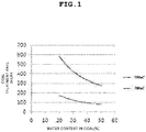
- FIG. 1 is a graph showing the simulation test results (SK pilot plant: capacity of 3 ton/day) of the coal treatment capacity depending on the content of water in coal when synthesis gas (350 °C) having passed through a gasifier and a heat exchanger and synthesis gas (700 °C) having not passed through the heat exchanger are respectively used as a heat source for drying water-containing coal in the dryer (integrated dryer) according to an embodiment of the present invention.
- dried coal and synthesis gas (specifically, steam-containing synthesis, which generally contains steam in an amount of 10 to 50 mol%) discharged from a dryer is transferred to a dried coal supply system including a solid-gas separator, a recovery unit for additionally separating and recovering a part of separated dried coal and a loop seal type transfer means for transferring residual dried coal to a gasifier.
- a dried coal supply system including a solid-gas separator, a recovery unit for additionally separating and recovering a part of separated dried coal and a loop seal type transfer means for transferring residual dried coal to a gasifier.
- products discharged from the dryer are separated into dried coal and synthesis gas by the solid-gas separator.
- the solid-gas separator a commonly-known solid-gas separator may be used as the solid-gas separator.
- a cyclone separator is an example of a typical solid-gas separator.
- the cyclone is an apparatus for separating particles existing in fluid (gas) using centrifugal force, and includes a tangential inlet for introducing solid-containing gas, an outlet for discharging solid-containing gas and an outlet for discharging collected solids.
- the cyclone includes a cylindrical portion and a conic portion connected to the cylindrical portion, and is configured such that the upper end of a downcomer is connected with the narrow lower end of the conic portion of the cyclone.
- the inlet of the downcomer is connected with the solid discharging outlet of the cyclone, and may have a pipe shape.
- the lower portion of the downcomer constitutes a part of the following loop seal type transfer means.
- the recovery unit may be a drain hopper, a continuous depressurization drain unit or the like.
- dried coal is obtained by removing a large amount of water from a feedstock, and may become high-quality coal existing in the form of particle when it is selectively pulverized before it is dried. Therefore, the dried coal has properties suitable for formation or fabrication into pellets, briquettes or granules. As such, the dried coal is advantageous in that it is a high value-added coal, and that, when it is formed or fabricated into a product, treatability and transportability as well as added value can be improved.
- the recovered dried coal may be formed into pellets using an organic or inorganic binder known in the related field.
- the organic binder may be acrylic emulsion, acryl-styrene emulsion, cellulose ether, polyvinyl alcohol, phenol resin, polyimide or a mixture thereof
- the inorganic binder may be bentonite or the like. Specifically, dried coal is mixed with the binder, and then the mixture is kneaded, pelletized by a forming machine and then dried and cooled to be formed into a product. If necessary, dried coal may be palletized without using the binder.
- a part of dried coal is heated to the softening point thereof, and is then pressurized to allow it to be agglomerated into naturally-present tar and pitch.
- the above-mentioned process of forming dried coal into a product can be illustratively understood. Therefore, another process of forming dried coal into a product, known in the related field, may be adopted as long as it can suitably utilize high-quality dried coal.
- non-recovered dried coal is transferred to a gasifier as a feedstock for a gasification reaction.
- the gasifier is operated at a pressure of several to several tens of kg/cm 2 . Therefore, the pressure of synthesis gas discharged from the gasifier is partially lowered during a process of transferring it to the dryer and a process of drying it in the dryer, and the pressure of the fuel supply unit and reaction unit of the gasifier is high compared to the pressure of the discharge unit of the gasifier, so the pressure of the dried coal is lower than the pressure in the gasifier. Therefore, in order to transfer (supply) the dried coal into the gasifier, that is, in order for solids to move from a low-pressure region to a high-pressure region, the dried coal must be supplied at pressure higher than the pressure in the gasifier.
- dried coal is transferred to the gasifier by forming a static head of the fluidized dried coal using a loop seal type transfer means.
- high-pressure (higher than pressure in loop seal structure) aeration gas is supplied through a plurality of ports provided in the loop seal structure.
- the supplied high-pressure aeration gas forms the coal inventory in the loop seal structure into a fluidized layer and maintains the fluidized layer, thus enabling the dried coal to be transferred to the gasifier.
- aeration gas nitrogen, carbon dioxide, steam, synthesis gas generated from the gasifier or a mixture thereof may be used.
- a gasifier various types of reactors known in the related field may be used.
- the gasifier is provided with a dried coal inlet and, if necessary, a gasifying agent inlet.
- a gasifier may include a moving-bed gasifier (dried carbonaceous feedstock is introduced into the upper portion thereof, and a gasifying agent comes into contact with the feed stock in a counterflow manner in the lower portion thereof), a fluidized-bed gasifier (a gasifying agent floats solid particles while passing through a carbonaceous feedstock bed), a transport reactor-integrated gasifier, a distributary flow gasifier (a carbonaceous feedstock and a gasifying agent are introduced in parallel), and the like.
- a moving-bed gasifier dried carbonaceous feedstock is introduced into the upper portion thereof, and a gasifying agent comes into contact with the feed stock in a counterflow manner in the lower portion thereof
- a fluidized-bed gasifier a gasifying agent floats solid particles while passing through a carbonaceous feedstock bed
- the operating temperature in the gasifier may be 400 to 1500 °C, specifically 800 to 1500 °C, and more specifically 900 to 1500 °C.
- the operating pressure in the gasifier may be 1 to 60 kg/cm 2 , specifically 5 to 40 kg/cm 2 , and more specifically 20 to 40 kg/cm 2 .
- the molar ratio of O 2 /C may be 0.1 to 1.0, and specifically 0.2 to 0.7.
- the molar ratio of steam/C may be substantially adjusted to 0 (in the case of a dry gasification reaction or a gasification reaction by reforming carbon dioxide.
- the molar ratio of steam/C may be 0 to 2, and specifically 0 to 1.
- the molar ratio of CO 2 /C may be 0 to 1, and specifically 0 to 0.5.
- the conversion ratio of carbon in coal may be 80% or more, and specifically 90 to 99%.
- the produced synthesis gas is discharged from the gasifier at high temperature depending on the operating temperature in the gasifier, this synthesis gas is directly recycled into the dryer without passing through a heat exchanger.
- FIG. 2 schematically shows an integrated drying and gasification process for co-producing synthesis gas, tar and high-quality coal using a loop seal type transfer means according to an embodiment ofthe present invention.
- the integrated drying gasification process largely includes a dryer 100, a pressurized dried coal supply system 200 and a gasifier 300. If not particularly mentioned, the constituents in the integrated drying gasification process may be connected with each other by a commonly-used connecting means, for example, a pipe, and coal and gas may be transferred there between through the connecting means.
- a commonly-used connecting means for example, a pipe
- water-containing coal is introduced into the lower portion of the dryer 100, and synthesis gas directly recycled from the gasifier 300 is also introduced into the lower portion of the dryer 100.
- the temperature of the synthesis gas discharged from the gasifier 300 is not greatly different from the operating temperature of the gasifier 300, but the synthesis gas may be cooled to 20 ⁇ 100 °C during the process of recycling this synthesis gas into the dryer 100.
- the dryer is designed to have a drying capacity higher than that of a dryer used in a general integrated drying and gasification process.
- dried coal and a gas mixture are discharged from the upper portion of the dryer 100, and the content of water in each of the discharged dried coal and gas mixture is determined depending on the temperature and pressure of synthesis gas introduced into the dryer 100, the initial water content and particle size of a water-containing coal feedstock and the mixing ratio of synthesis gas and coal (feedstock) introduced into the dryer 100.
- the weight ratio of synthesis gas and water-containing coal introduced into the dryer 100 may be 1:1 to 10:1, specifically 2:1 to 8:1, and more specifically 3:1 to 6:1.
- dried coal that is, dried solid fuel
- synthesis gas a gaseous component
- a solid component a solid component
- dried coal since the separated synthesis gas 102 may include dust, sulfur compounds, nitrogen compounds and the like, it may be additionally pass through a post-treatment process (not shown) provided with a filter (ceramic filter), an electric dust collector, a scrubber, a desulfurizer and the like.
- the synthesis gas 102 separated in this way may be supplied to a subsequent process such as an integrated gasification combined cycle (IGCC) process, an F-T process or the like.
- IGCC integrated gasification combined cycle
- F-T F-T
- a means or process for separating and recovering tar may be additionally provided.
- a means commonly used in the related field for example, filter or the like
- filter or the like may be used as the means for separating and recovering tar.
- dried coal separated by the cyclone 103 moves downwards along a downcomer 104 connected with the lower end of the cyclone 103 (accurately, the lower end of a conic portion of the cyclone 103).
- the downcomer 104 is provided at the lower portion thereof with a dried coal separation line 105, and the dried coal separation line 105 is connected with a drain hopper 106, thus recovering dried coal.
- the content ratio of separated and recovered dried coal to dried coal transferred to the gasifier may be suitably changed depending on the amount of a desired target product (synthesis gas or high-quality dried coal).
- the content ratio thereof by weight may be 1:1 to 4:1, and specifically 2:1 to 3:1.
- FIG. 3 shows the moving route of dried coal in the loop seal type transfer means in the integrated drying gasification process shown in FIG. 2 .
- the loop seal type transfer means 107 is provided with a plurality of aeration gas injecting ports.
- dried coal sequentially passes through the lower end of the downcomer 104, the horizontal region of the loop seal type transfer means 107 and the vertical region of the loop seal type transfer means 107 to be transferred toward the high-pressure gasifier 300.
- the transferred dried coal is gasified by various reaction routes (partial oxidation, carbon dioxide reforming, steam reforming, and combinations thereof) in the presence of a gasifying agent to produce synthesis gas.
- a gasifying agent supplied from the loop seal type transfer means
- the amount of the gasifying agent introduced into a gasifying agent injection port (inlet) provided in the gasifier maybe adjusted.
- the synthesis gas produced by the gasification reaction is partially or entirely recycled into the dryer 100 through a line 108.
- the conversion rate of water-containing coal into dried coal can be maximized.
- the molar ratio of carbon monoxide in the discharged synthesis gas may be 10 to 50%, and specifically 20 to 40%.
- coal dried by synthesis gas is supplied to a gasifier by a non-mechanical valve-type transfer means such as a loop seal type transfer means, so process equipment can be simplified and can be easily operated.
- the dryability of water-containing coal can be increased compared to a conventional technology in which synthesis gas is cooled by a heat exchanger disposed behind a gasifier and is then recycled to a dryer, and a part of dried coal is recovered as high-quality coal and is then formed into pellets, briquettes, granules and the like.
- tar which is caused by volatile components separated from coal according to the degree of the selective supply of heat to synthesis gas in the step of drying the water-containing coal, can be separated and recovered from the synthesis gas and can be formed into products.
- a loop seal type transfer means is used instead of a conventional lock hopper, so a process can be simplified and the problem of investment cost being increased by the increase in size of the transfer means can be overcome.
- a heat exchanger which is generally used in a conventional integrated drying and gasification process, is not needed, so equipment investment cost can be reduced.
- tar is additionally separated from synthesis gas and formed into products, thus increasing added value.
Landscapes
- Chemical & Material Sciences (AREA)
- Organic Chemistry (AREA)
- Oil, Petroleum & Natural Gas (AREA)
- Engineering & Computer Science (AREA)
- Geology (AREA)
- Life Sciences & Earth Sciences (AREA)
- Geochemistry & Mineralogy (AREA)
- General Life Sciences & Earth Sciences (AREA)
- Environmental & Geological Engineering (AREA)
- Combustion & Propulsion (AREA)
- Physics & Mathematics (AREA)
- Thermal Sciences (AREA)
- Mechanical Engineering (AREA)
- General Engineering & Computer Science (AREA)
- Solid Fuels And Fuel-Associated Substances (AREA)
- Industrial Gases (AREA)
Claims (21)
- Vergasungsverfahren zur gemeinsamen Herstellung von Synthesegas und Kohle hoher Qualität, umfassend die Schritte:a) Zuführen von wasserhaltiger Kohle zu einem Trockner;b) Trocknen der wasserhaltigen Kohle in dem Trockner, wobei die Wärmeenergie, die zum Trocknen der wasserhaltigen Kohle erforderlich ist, in Kontakt Synthesegas zugeführt wird, das von einem Vergasungsschritt zu dem Trockner rückgeführt wird;c) Trennen von getrockneter Kohle und Synthesegas, die aus dem Trockner abgeführt werden, unter Verwendung von Feststoff-Gas-Trennung und Gewinnen des abgetrennten Synthesegases;d) Gewinnen eines Teils der abgetrennten getrockneten Kohle und gleichzeitig Überführen der restlichen abgetrennten getrockneten Kohle zu einem Vergaser in einem fluiden Zustand unter Verwendung einer Überführungseinrichtung vom Gasverschlusstyp, zu der durch eine Vielzahl von Öffnungen Lüftungsgas zugeführt wird;e) Vergasen der überführten getrockneten Kohle in dem Vergaser, um Synthesegas zu erzeugen; undf) direktes Rückführen des aus dem Vergaser abgeführten Synthesegases mit 400 bis 1500 °C, ohne das Synthesegas durch einen oder mehrere Wärmetauscher zu führen,wobei der Trockner eine Trocknungskapazität bereitstellt, die zum Erzeugen der getrockneten Kohle, die aus der wasserhaltigen Kohle abgetrennt und gewonnen wird, und der getrockneten Kohle, die dem Vergasungsschritt zugeführt wird, erforderlich ist.
- Vergasungsverfahren gemäß Anspruch 1, wobei der Gehalt an Wasser in der wasserhaltigen Kohle 10 bis 70 Gew.-% beträgt.
- Vergasungsverfahren gemäß Anspruch 1, wobei die getrocknete Kohle einen Wassergehalt von 10 Gew.-% oder weniger aufweist.
- Vergasungsverfahren gemäß Anspruch 1, wobei die wasserhaltige Kohle vor Schritt a) auf eine Partikelgröße von 50 bis 6000 µm pulverisiert und dann in den Trockner eingeführt wird.
- Vergasungsverfahren gemäß Anspruch 1, wobei der Gehalt an Kohlenstoff in der wasserhaltigen Kohle wenigstens 20 Gew.-% beträgt.
- Vergasungsverfahren gemäß Anspruch 1, wobei der Trockner ein pneumatischer oder Schnelltrockner, ein Wirbelschichttrockner, ein Drehtrockner oder ein Drehrohrtrockner ist.
- Vergasungsverfahren gemäß Anspruch 6, wobei der Trockner ein pneumatischer oder Schnelltrockner ist.
- Vergasungsverfahren gemäß Anspruch 1, wobei die wasserhaltige Kohle und das Synthesegas in einem Parallelstrom in dem Trockner miteinander in Kontakt stehen.
- Vergasungsverfahren gemäß Anspruch 1, wobei der Betriebsdruck in dem Trockner 60 kg/cm2 oder weniger beträgt, die Betriebstemperatur an einem Einlass des Trockners auf einen Bereich von 400 bis 1500 °C eingestellt wird und die Betriebstemperatur an einem Auslass des Trockners auf einen Bereich von 200 bis 700 °C eingestellt wird.
- Vergasungsverfahren gemäß Anspruch 1, ferner umfassend den Schritt des Formens der bei Schritt d) abgetrennten und gewonnenen getrockneten Kohle zu Pellets, Briketts oder Granulat.
- Vergasungsverfahren gemäß Anspruch 1, wobei das Lüftungsgas Stickstoff, Kohlendioxid, Dampf, in dem Vergaser erzeugtes Synthesegas oder ein Gemisch davon ist.
- Vergasungsverfahren gemäß Anspruch 1, wobei die Betriebstemperatur in dem Vergaser 400 bis 1500 °C beträgt und der Betriebsdruck in dem Vergaser 1 bis 60 kg/cm2 beträgt.
- Vergasungsverfahren gemäß Anspruch 1, wobei bei Schritt e) das Molverhältnis von O2/C von 0,1 bis 1,0 beträgt und das Molverhältnis von CO2/C von 0 bis 1 beträgt.
- Vergasungsverfahren gemäß Anspruch 1, wobei bei Schritt e) das Molverhältnis von Dampf/C von 0 bis 2 beträgt.
- Vergasungsverfahren gemäß Anspruch 1, wobei das Gewichtsverhältnis von Synthesegas, das bei Schritt b) zu dem Trockner rückgeführt wird, zu wasserhaltiger Kohle von 1:1 bis 10:1 beträgt.
- Vergasungsverfahren gemäß Anspruch 1, wobei das Gewichtsverhältnis von getrockneter Kohle, die bei Schritt d) abgetrennt und gewonnen wird, zu getrockneter Kohle, die dem Vergaser zugeführt wird, von 1:1 bis 4:1 beträgt.
- Vergasungsverfahren gemäß Anspruch 1, ferner umfassend den Schritt des Abtrennens und Gewinnens von Teer, der bei dem Schritt des Trocknens der wasserhaltigen Kohle erzeugt wird und in dem Synthesegas bei dem Schritt c) des Gewinnens des Synthesegases enthalten ist.
- Vergasungsverfahren gemäß Anspruch 17, wobei der Trockner eine Wärmekapazität bereitstellt, die größer als die Trocknungskapazität ist, die zum Erzeugen der getrockneten Kohle, die aus der wasserhaltigen Kohle abgetrennt und gewonnen wird, und der getrockneten Kohle, die dem Vergasungsschritt zugeführt wird, erforderlich ist.
- Integriertes Trocknungs- und Vergasungssystem, umfassend:einen Vergaser;einen Trockner, der vor dem Vergase angeordnet ist, zum Trocknen von wasserhaltiger Kohle in Kontakt mit Synthesegas, das von dem Vergaser rückgeführt wird, und dann Abführen von getrockneter Kohle und Synthesegas;eine Feststoff-Gas-Trennvorrichtung zum Trennen der getrockneten Kohle und des Synthesegases, die aus dem Trockner abgeführt werden;eine Gewinnungseinheit zum Abtrennen und Gewinnen eines Teils der von dem Feststoff-Gas-Trennvorrichtung abgetrennten getrockneten Kohle; undeine Überführungseinheit vom Gasverschlusstyp, die die restliche Kohle, die nicht von der Gewinnungseinheit gewonnen wird, zu dem Vergaser überführt, und die eine Vielzahl von Lüftungsgaseinlässen umfasst,wobei das von dem Vergaser abgeführte Synthesegas direkt zu dem Trockner rückgeführt wird, ohne durch einen Wärmetauscher zu treten, und der Trockner eine Trocknungskapazität bereitstellt, die zum Erzeugen der getrockneten Kohle, die aus der wasserhaltigen Kohle abgetrennt und gewonnen wird, und der getrockneten Kohle, die dem Vergasungsschritt zugeführt wird, erforderlich ist.
- Integriertes Trocknungs- und Vergasungssystem gemäß Anspruch 19, ferner umfassend eine Gewinnungseinheit zum Abtrennen und Gewinnen von Teer, der in dem von der Feststoff-Gas-Trennvorrichtung abgetrennten Synthesegas enthalten ist.
- Integriertes Trocknungs- und Vergasungssystem gemäß Anspruch 19, wobei die Gewinnungseinheit zum Gewinnen der getrockneten kohle ein Ablauftrichter oder eine kontinuierliche Drucklösungs-Ablaufeinheit ist.
Applications Claiming Priority (2)
| Application Number | Priority Date | Filing Date | Title |
|---|---|---|---|
| KR1020120149326A KR101890951B1 (ko) | 2012-12-20 | 2012-12-20 | 합성 가스 및 고품위 석탄의 동시 생산을 위한 건조 및 가스화 통합 공정 |
| PCT/KR2013/011812 WO2014098472A1 (ko) | 2012-12-20 | 2013-12-18 | 합성 가스 및 고품위 석탄의 동시 생산을 위한 건조 및 가스화 통합 공정 |
Publications (3)
| Publication Number | Publication Date |
|---|---|
| EP2937405A1 EP2937405A1 (de) | 2015-10-28 |
| EP2937405A4 EP2937405A4 (de) | 2016-09-07 |
| EP2937405B1 true EP2937405B1 (de) | 2019-02-13 |
Family
ID=50978715
Family Applications (1)
| Application Number | Title | Priority Date | Filing Date |
|---|---|---|---|
| EP13866242.4A Active EP2937405B1 (de) | 2012-12-20 | 2013-12-18 | Integriertes trocknungs- und vergasungsverfahren zur gleichzeitigen herstellung von synthesegas und kohle mit hohem inkohlungsgrad |
Country Status (5)
| Country | Link |
|---|---|
| US (2) | US9909076B2 (de) |
| EP (1) | EP2937405B1 (de) |
| KR (1) | KR101890951B1 (de) |
| CN (1) | CN105121607B (de) |
| WO (1) | WO2014098472A1 (de) |
Families Citing this family (8)
| Publication number | Priority date | Publication date | Assignee | Title |
|---|---|---|---|---|
| BR112022025586A2 (pt) | 2020-06-15 | 2023-03-07 | Res Inst Nationwide Childrens Hospital | Liberação de vetor de vírus adenoassociado para distrofias musculares |
| CN113025385B (zh) * | 2021-04-21 | 2022-05-27 | 昆明理工大学 | 一种旋转式生物质流化床气化装置 |
| EP4426832A1 (de) | 2021-11-03 | 2024-09-11 | The J. David Gladstone Institutes, A Testamentary Trust Established under The Will of J. David Gladstone | Genaue genomeditierung mit retrons |
| CN119562807A (zh) | 2022-05-30 | 2025-03-04 | 生物技术公司 | 用于递送核酸的复合物 |
| CN120225219A (zh) | 2022-09-23 | 2025-06-27 | 生物技术欧洲股份公司 | 用于递送肝期抗原的组合物及相关方法 |
| AU2023347390A1 (en) | 2022-09-23 | 2025-04-10 | BioNTech SE | Compositions for delivery of plasmodium csp antigens and related methods |
| AU2023357320A1 (en) | 2022-10-06 | 2025-04-17 | BioNTech SE | Rna compositions targeting claudin-18.2 |
| WO2026082899A2 (en) | 2024-10-16 | 2026-04-23 | BioNTech SE | Rna for preventing or treating tuberculosis |
Family Cites Families (21)
| Publication number | Priority date | Publication date | Assignee | Title |
|---|---|---|---|---|
| US3817723A (en) * | 1972-03-23 | 1974-06-18 | Secretary | Two-stage gasification of pretreated coal |
| US3985519A (en) | 1972-03-28 | 1976-10-12 | Exxon Research And Engineering Company | Hydrogasification process |
| CA2134871C (en) * | 1992-05-08 | 2001-12-18 | Terence R. Johnson | Integrated carbonaceous fuel drying and gasification process and apparatus |
| US5937652A (en) * | 1992-11-16 | 1999-08-17 | Abdelmalek; Fawzy T. | Process for coal or biomass fuel gasification by carbon dioxide extracted from a boiler flue gas stream |
| US5685138A (en) | 1995-02-09 | 1997-11-11 | Fluor Corporation | Integrated drying of feedstock feed to IGCC plant |
| US7922782B2 (en) * | 2006-06-01 | 2011-04-12 | Greatpoint Energy, Inc. | Catalytic steam gasification process with recovery and recycle of alkali metal compounds |
| US8152874B2 (en) * | 2006-06-19 | 2012-04-10 | Siemens Energy, Inc. | Systems and methods for integration of gasification and reforming processes |
| CN101220298B (zh) * | 2007-01-10 | 2010-12-15 | 中国科学院工程热物理研究所 | 循环流化床热解气化方法及装置 |
| US8217210B2 (en) * | 2007-08-27 | 2012-07-10 | Purdue Research Foundation | Integrated gasification—pyrolysis process |
| FR2925915B1 (fr) * | 2007-12-26 | 2010-10-08 | Total France | Procede et chaine de traitement pour la conversion thermochimique par gazeification d'une charge humide de materiau biologique, notamment de la biomasse ou du charbon. |
| JP5417753B2 (ja) * | 2008-07-11 | 2014-02-19 | 株式会社Ihi | 循環流動層ガス化炉 |
| TWI558807B (zh) * | 2008-12-17 | 2016-11-21 | 祿幕斯科技公司 | 包含分段漿料添加之氣化系統及方法 |
| TR201111917T1 (tr) | 2009-06-05 | 2012-05-21 | Synthesis Energy Systems, Inc. | Siklonlu ve akışkan yataklı bir reaktörden katı maddeleri geri dönüştürmek için sızdırmazlık döngüsü ve bunun kullanım yöntemi. |
| US20100313442A1 (en) * | 2009-06-12 | 2010-12-16 | Steven Craig Russell | Method of using syngas cooling to heat drying gas for a dry feed system |
| US8961629B2 (en) * | 2009-12-21 | 2015-02-24 | Southern Company Services, Inc. | Apparatus, components and operating methods for circulating fluidized bed transport gasifiers and reactors |
| JP5578907B2 (ja) | 2010-03-29 | 2014-08-27 | 三菱重工業株式会社 | 石炭ガス化複合発電プラント |
| CN102453551A (zh) | 2010-10-14 | 2012-05-16 | 通用电气公司 | 集成干燥和气化固体燃料颗粒的系统及方法 |
| CN201873648U (zh) * | 2010-11-20 | 2011-06-22 | 山东百川同创能源有限公司 | 高含水率中药渣干燥处理及热解气化系统 |
| CN102021035B (zh) | 2010-11-24 | 2014-07-30 | 北京低碳清洁能源研究所 | 从煤和生物质制备固体、液体和气体产物的系统以及使用所述系统的方法 |
| US8945507B2 (en) * | 2011-04-21 | 2015-02-03 | Kellogg Brown & Root Llc | Systems and methods for operating a gasifier |
| EP2707663A4 (de) * | 2011-05-09 | 2015-04-08 | Hrl Treasury Idgcc Pty Ltd | Verbesserungen an einer vergasung mit integrierter trocknung |
-
2012
- 2012-12-20 KR KR1020120149326A patent/KR101890951B1/ko active Active
-
2013
- 2013-12-18 EP EP13866242.4A patent/EP2937405B1/de active Active
- 2013-12-18 CN CN201380070795.7A patent/CN105121607B/zh active Active
- 2013-12-18 WO PCT/KR2013/011812 patent/WO2014098472A1/ko not_active Ceased
- 2013-12-18 US US14/653,339 patent/US9909076B2/en active Active
-
2018
- 2018-01-16 US US15/872,340 patent/US10023817B2/en active Active
Non-Patent Citations (1)
| Title |
|---|
| None * |
Also Published As
| Publication number | Publication date |
|---|---|
| US9909076B2 (en) | 2018-03-06 |
| CN105121607B (zh) | 2019-01-18 |
| WO2014098472A1 (ko) | 2014-06-26 |
| KR101890951B1 (ko) | 2018-08-22 |
| US20180142171A1 (en) | 2018-05-24 |
| US20150361361A1 (en) | 2015-12-17 |
| KR20140080010A (ko) | 2014-06-30 |
| US10023817B2 (en) | 2018-07-17 |
| EP2937405A4 (de) | 2016-09-07 |
| CN105121607A (zh) | 2015-12-02 |
| EP2937405A1 (de) | 2015-10-28 |
Similar Documents
| Publication | Publication Date | Title |
|---|---|---|
| US10023817B2 (en) | Integrated drying and gasification process for simultaneously producing synthetic gas and high rank coal | |
| CA2852761C (en) | Gasifier fluidization | |
| CA2624626C (en) | Catalytic steam gasification of petroleum coke to methane | |
| EP2737034B1 (de) | Vergasungsverfahren | |
| US9163179B2 (en) | System and method for production of Fischer-Tropsch synthesis products and power | |
| CN106590761B (zh) | 煤催化气化制富甲烷合成气的流化床反应装置及反应方法 | |
| US10106753B1 (en) | Coal gasification process with conversion of CO2 to oxygen gasifier feed producing carbon by-product | |
| WO2014093308A1 (en) | Second stage gasifier in staged gasification | |
| EP2933317B1 (de) | Vergasungsverfahren und system mit trockner mit integriertem wasser-gas-konvertierungskatalysator | |
| KR102032823B1 (ko) | 열 교환기가 구비된 순환 유동층 가스화기 | |
| Watkinson et al. | 15 Gasification, pyrolysis, and | |
| CN109401792A (zh) | 催化气化组合流化床反应装置及反应方法 | |
| Sharma | Hydrogen Production from Coal | |
| CN111057585A (zh) | 煤流化气化的方法 |
Legal Events
| Date | Code | Title | Description |
|---|---|---|---|
| PUAI | Public reference made under article 153(3) epc to a published international application that has entered the european phase |
Free format text: ORIGINAL CODE: 0009012 |
|
| 17P | Request for examination filed |
Effective date: 20150717 |
|
| AK | Designated contracting states |
Kind code of ref document: A1 Designated state(s): AL AT BE BG CH CY CZ DE DK EE ES FI FR GB GR HR HU IE IS IT LI LT LU LV MC MK MT NL NO PL PT RO RS SE SI SK SM TR |
|
| AX | Request for extension of the european patent |
Extension state: BA ME |
|
| DAX | Request for extension of the european patent (deleted) | ||
| A4 | Supplementary search report drawn up and despatched |
Effective date: 20160805 |
|
| RIC1 | Information provided on ipc code assigned before grant |
Ipc: C10L 5/02 20060101ALI20160801BHEP Ipc: C10J 3/48 20060101AFI20160801BHEP |
|
| GRAP | Despatch of communication of intention to grant a patent |
Free format text: ORIGINAL CODE: EPIDOSNIGR1 |
|
| STAA | Information on the status of an ep patent application or granted ep patent |
Free format text: STATUS: GRANT OF PATENT IS INTENDED |
|
| INTG | Intention to grant announced |
Effective date: 20180917 |
|
| GRAS | Grant fee paid |
Free format text: ORIGINAL CODE: EPIDOSNIGR3 |
|
| GRAA | (expected) grant |
Free format text: ORIGINAL CODE: 0009210 |
|
| STAA | Information on the status of an ep patent application or granted ep patent |
Free format text: STATUS: THE PATENT HAS BEEN GRANTED |
|
| AK | Designated contracting states |
Kind code of ref document: B1 Designated state(s): AL AT BE BG CH CY CZ DE DK EE ES FI FR GB GR HR HU IE IS IT LI LT LU LV MC MK MT NL NO PL PT RO RS SE SI SK SM TR |
|
| REG | Reference to a national code |
Ref country code: GB Ref legal event code: FG4D |
|
| REG | Reference to a national code |
Ref country code: CH Ref legal event code: EP Ref country code: AT Ref legal event code: REF Ref document number: 1096226 Country of ref document: AT Kind code of ref document: T Effective date: 20190215 |
|
| REG | Reference to a national code |
Ref country code: IE Ref legal event code: FG4D |
|
| REG | Reference to a national code |
Ref country code: DE Ref legal event code: R096 Ref document number: 602013050849 Country of ref document: DE |
|
| REG | Reference to a national code |
Ref country code: LT Ref legal event code: MG4D |
|
| REG | Reference to a national code |
Ref country code: NL Ref legal event code: MP Effective date: 20190213 |
|
| PG25 | Lapsed in a contracting state [announced via postgrant information from national office to epo] |
Ref country code: SE Free format text: LAPSE BECAUSE OF FAILURE TO SUBMIT A TRANSLATION OF THE DESCRIPTION OR TO PAY THE FEE WITHIN THE PRESCRIBED TIME-LIMIT Effective date: 20190213 Ref country code: NL Free format text: LAPSE BECAUSE OF FAILURE TO SUBMIT A TRANSLATION OF THE DESCRIPTION OR TO PAY THE FEE WITHIN THE PRESCRIBED TIME-LIMIT Effective date: 20190213 Ref country code: PT Free format text: LAPSE BECAUSE OF FAILURE TO SUBMIT A TRANSLATION OF THE DESCRIPTION OR TO PAY THE FEE WITHIN THE PRESCRIBED TIME-LIMIT Effective date: 20190613 Ref country code: FI Free format text: LAPSE BECAUSE OF FAILURE TO SUBMIT A TRANSLATION OF THE DESCRIPTION OR TO PAY THE FEE WITHIN THE PRESCRIBED TIME-LIMIT Effective date: 20190213 Ref country code: NO Free format text: LAPSE BECAUSE OF FAILURE TO SUBMIT A TRANSLATION OF THE DESCRIPTION OR TO PAY THE FEE WITHIN THE PRESCRIBED TIME-LIMIT Effective date: 20190513 Ref country code: LT Free format text: LAPSE BECAUSE OF FAILURE TO SUBMIT A TRANSLATION OF THE DESCRIPTION OR TO PAY THE FEE WITHIN THE PRESCRIBED TIME-LIMIT Effective date: 20190213 |
|
| PG25 | Lapsed in a contracting state [announced via postgrant information from national office to epo] |
Ref country code: IS Free format text: LAPSE BECAUSE OF FAILURE TO SUBMIT A TRANSLATION OF THE DESCRIPTION OR TO PAY THE FEE WITHIN THE PRESCRIBED TIME-LIMIT Effective date: 20190613 Ref country code: GR Free format text: LAPSE BECAUSE OF FAILURE TO SUBMIT A TRANSLATION OF THE DESCRIPTION OR TO PAY THE FEE WITHIN THE PRESCRIBED TIME-LIMIT Effective date: 20190514 Ref country code: HR Free format text: LAPSE BECAUSE OF FAILURE TO SUBMIT A TRANSLATION OF THE DESCRIPTION OR TO PAY THE FEE WITHIN THE PRESCRIBED TIME-LIMIT Effective date: 20190213 Ref country code: LV Free format text: LAPSE BECAUSE OF FAILURE TO SUBMIT A TRANSLATION OF THE DESCRIPTION OR TO PAY THE FEE WITHIN THE PRESCRIBED TIME-LIMIT Effective date: 20190213 Ref country code: RS Free format text: LAPSE BECAUSE OF FAILURE TO SUBMIT A TRANSLATION OF THE DESCRIPTION OR TO PAY THE FEE WITHIN THE PRESCRIBED TIME-LIMIT Effective date: 20190213 Ref country code: BG Free format text: LAPSE BECAUSE OF FAILURE TO SUBMIT A TRANSLATION OF THE DESCRIPTION OR TO PAY THE FEE WITHIN THE PRESCRIBED TIME-LIMIT Effective date: 20190513 |
|
| REG | Reference to a national code |
Ref country code: DE Ref legal event code: R082 Ref document number: 602013050849 Country of ref document: DE Representative=s name: MATHYS & SQUIRE EUROPE LLP, DE Ref country code: DE Ref legal event code: R082 Ref document number: 602013050849 Country of ref document: DE Representative=s name: MATHYS & SQUIRE GBR, DE Ref country code: DE Ref legal event code: R082 Ref document number: 602013050849 Country of ref document: DE Representative=s name: MATHYS & SQUIRE EUROPE PATENTANWAELTE PARTNERS, DE |
|
| REG | Reference to a national code |
Ref country code: AT Ref legal event code: MK05 Ref document number: 1096226 Country of ref document: AT Kind code of ref document: T Effective date: 20190213 |
|
| PG25 | Lapsed in a contracting state [announced via postgrant information from national office to epo] |
Ref country code: CZ Free format text: LAPSE BECAUSE OF FAILURE TO SUBMIT A TRANSLATION OF THE DESCRIPTION OR TO PAY THE FEE WITHIN THE PRESCRIBED TIME-LIMIT Effective date: 20190213 Ref country code: ES Free format text: LAPSE BECAUSE OF FAILURE TO SUBMIT A TRANSLATION OF THE DESCRIPTION OR TO PAY THE FEE WITHIN THE PRESCRIBED TIME-LIMIT Effective date: 20190213 Ref country code: RO Free format text: LAPSE BECAUSE OF FAILURE TO SUBMIT A TRANSLATION OF THE DESCRIPTION OR TO PAY THE FEE WITHIN THE PRESCRIBED TIME-LIMIT Effective date: 20190213 Ref country code: IT Free format text: LAPSE BECAUSE OF FAILURE TO SUBMIT A TRANSLATION OF THE DESCRIPTION OR TO PAY THE FEE WITHIN THE PRESCRIBED TIME-LIMIT Effective date: 20190213 Ref country code: EE Free format text: LAPSE BECAUSE OF FAILURE TO SUBMIT A TRANSLATION OF THE DESCRIPTION OR TO PAY THE FEE WITHIN THE PRESCRIBED TIME-LIMIT Effective date: 20190213 Ref country code: DK Free format text: LAPSE BECAUSE OF FAILURE TO SUBMIT A TRANSLATION OF THE DESCRIPTION OR TO PAY THE FEE WITHIN THE PRESCRIBED TIME-LIMIT Effective date: 20190213 Ref country code: SK Free format text: LAPSE BECAUSE OF FAILURE TO SUBMIT A TRANSLATION OF THE DESCRIPTION OR TO PAY THE FEE WITHIN THE PRESCRIBED TIME-LIMIT Effective date: 20190213 Ref country code: AL Free format text: LAPSE BECAUSE OF FAILURE TO SUBMIT A TRANSLATION OF THE DESCRIPTION OR TO PAY THE FEE WITHIN THE PRESCRIBED TIME-LIMIT Effective date: 20190213 |
|
| REG | Reference to a national code |
Ref country code: DE Ref legal event code: R097 Ref document number: 602013050849 Country of ref document: DE |
|
| PG25 | Lapsed in a contracting state [announced via postgrant information from national office to epo] |
Ref country code: PL Free format text: LAPSE BECAUSE OF FAILURE TO SUBMIT A TRANSLATION OF THE DESCRIPTION OR TO PAY THE FEE WITHIN THE PRESCRIBED TIME-LIMIT Effective date: 20190213 Ref country code: SM Free format text: LAPSE BECAUSE OF FAILURE TO SUBMIT A TRANSLATION OF THE DESCRIPTION OR TO PAY THE FEE WITHIN THE PRESCRIBED TIME-LIMIT Effective date: 20190213 |
|
| PLBE | No opposition filed within time limit |
Free format text: ORIGINAL CODE: 0009261 |
|
| STAA | Information on the status of an ep patent application or granted ep patent |
Free format text: STATUS: NO OPPOSITION FILED WITHIN TIME LIMIT |
|
| PG25 | Lapsed in a contracting state [announced via postgrant information from national office to epo] |
Ref country code: AT Free format text: LAPSE BECAUSE OF FAILURE TO SUBMIT A TRANSLATION OF THE DESCRIPTION OR TO PAY THE FEE WITHIN THE PRESCRIBED TIME-LIMIT Effective date: 20190213 |
|
| 26N | No opposition filed |
Effective date: 20191114 |
|
| PG25 | Lapsed in a contracting state [announced via postgrant information from national office to epo] |
Ref country code: SI Free format text: LAPSE BECAUSE OF FAILURE TO SUBMIT A TRANSLATION OF THE DESCRIPTION OR TO PAY THE FEE WITHIN THE PRESCRIBED TIME-LIMIT Effective date: 20190213 |
|
| PG25 | Lapsed in a contracting state [announced via postgrant information from national office to epo] |
Ref country code: TR Free format text: LAPSE BECAUSE OF FAILURE TO SUBMIT A TRANSLATION OF THE DESCRIPTION OR TO PAY THE FEE WITHIN THE PRESCRIBED TIME-LIMIT Effective date: 20190213 |
|
| REG | Reference to a national code |
Ref country code: CH Ref legal event code: PL |
|
| REG | Reference to a national code |
Ref country code: BE Ref legal event code: MM Effective date: 20191231 |
|
| PG25 | Lapsed in a contracting state [announced via postgrant information from national office to epo] |
Ref country code: MC Free format text: LAPSE BECAUSE OF FAILURE TO SUBMIT A TRANSLATION OF THE DESCRIPTION OR TO PAY THE FEE WITHIN THE PRESCRIBED TIME-LIMIT Effective date: 20190213 |
|
| PG25 | Lapsed in a contracting state [announced via postgrant information from national office to epo] |
Ref country code: LU Free format text: LAPSE BECAUSE OF NON-PAYMENT OF DUE FEES Effective date: 20191218 Ref country code: IE Free format text: LAPSE BECAUSE OF NON-PAYMENT OF DUE FEES Effective date: 20191218 |
|
| PG25 | Lapsed in a contracting state [announced via postgrant information from national office to epo] |
Ref country code: LI Free format text: LAPSE BECAUSE OF NON-PAYMENT OF DUE FEES Effective date: 20191231 Ref country code: BE Free format text: LAPSE BECAUSE OF NON-PAYMENT OF DUE FEES Effective date: 20191231 Ref country code: CH Free format text: LAPSE BECAUSE OF NON-PAYMENT OF DUE FEES Effective date: 20191231 |
|
| REG | Reference to a national code |
Ref country code: DE Ref legal event code: R082 Ref document number: 602013050849 Country of ref document: DE Representative=s name: MATHYS & SQUIRE GBR, DE Ref country code: DE Ref legal event code: R082 Ref document number: 602013050849 Country of ref document: DE Representative=s name: MATHYS & SQUIRE EUROPE PATENTANWAELTE PARTNERS, DE |
|
| PG25 | Lapsed in a contracting state [announced via postgrant information from national office to epo] |
Ref country code: CY Free format text: LAPSE BECAUSE OF FAILURE TO SUBMIT A TRANSLATION OF THE DESCRIPTION OR TO PAY THE FEE WITHIN THE PRESCRIBED TIME-LIMIT Effective date: 20190213 |
|
| PG25 | Lapsed in a contracting state [announced via postgrant information from national office to epo] |
Ref country code: HU Free format text: LAPSE BECAUSE OF FAILURE TO SUBMIT A TRANSLATION OF THE DESCRIPTION OR TO PAY THE FEE WITHIN THE PRESCRIBED TIME-LIMIT; INVALID AB INITIO Effective date: 20131218 Ref country code: MT Free format text: LAPSE BECAUSE OF FAILURE TO SUBMIT A TRANSLATION OF THE DESCRIPTION OR TO PAY THE FEE WITHIN THE PRESCRIBED TIME-LIMIT Effective date: 20190213 |
|
| PG25 | Lapsed in a contracting state [announced via postgrant information from national office to epo] |
Ref country code: MK Free format text: LAPSE BECAUSE OF FAILURE TO SUBMIT A TRANSLATION OF THE DESCRIPTION OR TO PAY THE FEE WITHIN THE PRESCRIBED TIME-LIMIT Effective date: 20190213 |
|
| P01 | Opt-out of the competence of the unified patent court (upc) registered |
Effective date: 20230622 |
|
| PGFP | Annual fee paid to national office [announced via postgrant information from national office to epo] |
Ref country code: DE Payment date: 20251002 Year of fee payment: 13 |
|
| PGFP | Annual fee paid to national office [announced via postgrant information from national office to epo] |
Ref country code: GB Payment date: 20251001 Year of fee payment: 13 |
|
| PGFP | Annual fee paid to national office [announced via postgrant information from national office to epo] |
Ref country code: FR Payment date: 20251001 Year of fee payment: 13 |