EP2937203B1 - Blow moulding machine and method with an automatically operated ground and/or side coupling - Google Patents
Blow moulding machine and method with an automatically operated ground and/or side coupling Download PDFInfo
- Publication number
- EP2937203B1 EP2937203B1 EP15165096.7A EP15165096A EP2937203B1 EP 2937203 B1 EP2937203 B1 EP 2937203B1 EP 15165096 A EP15165096 A EP 15165096A EP 2937203 B1 EP2937203 B1 EP 2937203B1
- Authority
- EP
- European Patent Office
- Prior art keywords
- base part
- release element
- support
- side part
- fastening mechanism
- Prior art date
- Legal status (The legal status is an assumption and is not a legal conclusion. Google has not performed a legal analysis and makes no representation as to the accuracy of the status listed.)
- Active
Links
Images

Classifications
-
- B—PERFORMING OPERATIONS; TRANSPORTING
- B29—WORKING OF PLASTICS; WORKING OF SUBSTANCES IN A PLASTIC STATE IN GENERAL
- B29D—PRODUCING PARTICULAR ARTICLES FROM PLASTICS OR FROM SUBSTANCES IN A PLASTIC STATE
- B29D22/00—Producing hollow articles
- B29D22/003—Containers for packaging, storing or transporting, e.g. bottles, jars, cans, barrels, tanks
-
- B—PERFORMING OPERATIONS; TRANSPORTING
- B29—WORKING OF PLASTICS; WORKING OF SUBSTANCES IN A PLASTIC STATE IN GENERAL
- B29C—SHAPING OR JOINING OF PLASTICS; SHAPING OF MATERIAL IN A PLASTIC STATE, NOT OTHERWISE PROVIDED FOR; AFTER-TREATMENT OF THE SHAPED PRODUCTS, e.g. REPAIRING
- B29C49/00—Blow-moulding, i.e. blowing a preform or parison to a desired shape within a mould; Apparatus therefor
- B29C49/42—Component parts, details or accessories; Auxiliary operations
- B29C49/48—Moulds
- B29C49/4823—Moulds with incorporated heating or cooling means
- B29C2049/4825—Moulds with incorporated heating or cooling means for cooling moulds or mould parts
- B29C2049/483—Moulds with incorporated heating or cooling means for cooling moulds or mould parts in different areas of the mould at different temperatures, e.g. neck, shoulder or bottom
-
- B—PERFORMING OPERATIONS; TRANSPORTING
- B29—WORKING OF PLASTICS; WORKING OF SUBSTANCES IN A PLASTIC STATE IN GENERAL
- B29C—SHAPING OR JOINING OF PLASTICS; SHAPING OF MATERIAL IN A PLASTIC STATE, NOT OTHERWISE PROVIDED FOR; AFTER-TREATMENT OF THE SHAPED PRODUCTS, e.g. REPAIRING
- B29C49/00—Blow-moulding, i.e. blowing a preform or parison to a desired shape within a mould; Apparatus therefor
- B29C49/42—Component parts, details or accessories; Auxiliary operations
- B29C49/48—Moulds
- B29C49/4823—Moulds with incorporated heating or cooling means
- B29C2049/4838—Moulds with incorporated heating or cooling means for heating moulds or mould parts
- B29C2049/4846—Moulds with incorporated heating or cooling means for heating moulds or mould parts in different areas of the mould at different temperatures, e.g. neck, shoulder or bottom
- B29C2049/4848—Bottom
-
- B—PERFORMING OPERATIONS; TRANSPORTING
- B29—WORKING OF PLASTICS; WORKING OF SUBSTANCES IN A PLASTIC STATE IN GENERAL
- B29C—SHAPING OR JOINING OF PLASTICS; SHAPING OF MATERIAL IN A PLASTIC STATE, NOT OTHERWISE PROVIDED FOR; AFTER-TREATMENT OF THE SHAPED PRODUCTS, e.g. REPAIRING
- B29C49/00—Blow-moulding, i.e. blowing a preform or parison to a desired shape within a mould; Apparatus therefor
- B29C49/42—Component parts, details or accessories; Auxiliary operations
- B29C49/48—Moulds
- B29C2049/4856—Mounting, exchanging or centering moulds or parts thereof
- B29C2049/4858—Exchanging mould parts, e.g. for changing the mould size or geometry for making different products in the same mould
-
- B—PERFORMING OPERATIONS; TRANSPORTING
- B29—WORKING OF PLASTICS; WORKING OF SUBSTANCES IN A PLASTIC STATE IN GENERAL
- B29C—SHAPING OR JOINING OF PLASTICS; SHAPING OF MATERIAL IN A PLASTIC STATE, NOT OTHERWISE PROVIDED FOR; AFTER-TREATMENT OF THE SHAPED PRODUCTS, e.g. REPAIRING
- B29C49/00—Blow-moulding, i.e. blowing a preform or parison to a desired shape within a mould; Apparatus therefor
- B29C49/42—Component parts, details or accessories; Auxiliary operations
- B29C49/48—Moulds
- B29C2049/4879—Moulds characterised by mould configurations
- B29C2049/4892—Mould halves consisting of an independent main and bottom part
-
- B—PERFORMING OPERATIONS; TRANSPORTING
- B29—WORKING OF PLASTICS; WORKING OF SUBSTANCES IN A PLASTIC STATE IN GENERAL
- B29C—SHAPING OR JOINING OF PLASTICS; SHAPING OF MATERIAL IN A PLASTIC STATE, NOT OTHERWISE PROVIDED FOR; AFTER-TREATMENT OF THE SHAPED PRODUCTS, e.g. REPAIRING
- B29C49/00—Blow-moulding, i.e. blowing a preform or parison to a desired shape within a mould; Apparatus therefor
- B29C49/42—Component parts, details or accessories; Auxiliary operations
- B29C49/64—Heating or cooling preforms, parisons or blown articles
- B29C49/6604—Thermal conditioning of the blown article
- B29C2049/6606—Cooling the article
- B29C2049/6676—Cooling the article the medium being oriented towards special areas of the blown article
- B29C2049/6692—Bottom area
-
- B—PERFORMING OPERATIONS; TRANSPORTING
- B29—WORKING OF PLASTICS; WORKING OF SUBSTANCES IN A PLASTIC STATE IN GENERAL
- B29C—SHAPING OR JOINING OF PLASTICS; SHAPING OF MATERIAL IN A PLASTIC STATE, NOT OTHERWISE PROVIDED FOR; AFTER-TREATMENT OF THE SHAPED PRODUCTS, e.g. REPAIRING
- B29C49/00—Blow-moulding, i.e. blowing a preform or parison to a desired shape within a mould; Apparatus therefor
- B29C49/42—Component parts, details or accessories; Auxiliary operations
- B29C49/64—Heating or cooling preforms, parisons or blown articles
- B29C49/6604—Thermal conditioning of the blown article
- B29C49/6605—Heating the article, e.g. for hot fill
-
- B—PERFORMING OPERATIONS; TRANSPORTING
- B29—WORKING OF PLASTICS; WORKING OF SUBSTANCES IN A PLASTIC STATE IN GENERAL
- B29L—INDEXING SCHEME ASSOCIATED WITH SUBCLASS B29C, RELATING TO PARTICULAR ARTICLES
- B29L2031/00—Other particular articles
- B29L2031/712—Containers; Packaging elements or accessories, Packages
- B29L2031/7158—Bottles
Definitions
- the present invention relates to an apparatus and a method for forming plastic preforms into plastic containers. Such devices and methods have been known for a long time from the prior art.
- heated plastic preforms are usually supplied to a blow molding device, such as in particular a stretch blow molding machine, and expanded from this to plastic containers.
- blow molding machines usually have a plurality of blowing stations, which in turn are equipped with blow molds, in the interior of which the plastic preforms are formed by applying compressed air to the plastic containers and in particular to plastic bottles.
- blow molds in the interior of which the plastic preforms are formed by applying compressed air to the plastic containers and in particular to plastic bottles.
- the DE 10 2010 048 720 A1 describes a quick-mount bottom mold with additional holding force support.
- a rotary movement of a locking element by means of a rotary movement of a locking element, a release of the bottom part of the blow mold can be achieved by a carrier.
- the EP 1 299 223 B1 describes a device for blow molding containers.
- a hand lever for releasing the bottom part is used.
- an automated solution of the bottom part is prevented.
- the walls are tempered, for example, cooled.
- the corresponding blow molding devices or their side parts or their bottom parts on Temperierkanäle within which a temperature control can flow.
- These tempering channels are connected to a coolant supply, for example to a water supply, and thus the temperature control can be achieved or maintained during operation.
- the present invention has for its object to provide an apparatus and a method available which allow a comparatively quick change operation of the blow molding and which should preferably also allow at least semi-automatic change of blow moldings.
- An inventive device for forming plastic preforms to plastic containers has at least one forming station, which in turn has a blow mold, within which the plastic preforms are expandable by exposure to a gaseous medium.
- the blow mold on a bottom part which is detachably (and at least indirectly) arranged on a support.
- the device has a fastening mechanism in order to fasten the blow mold and in particular the bottom part to this support.
- the device in particular the forming station, has at least one first connection device in order to supply the device, in particular the forming station and in particular also the bottom part, with a flowable temperature control medium, this supply of the temperature control medium via the connection device (in particular by means of a flow passing through the connection device) a distance or a removal movement of the bottom part of the carrier is separable or interruptible.
- this fastening mechanism has a releasable in a predetermined straight direction release element, wherein the attachment of the bottom part to the carrier is releasable by a displacement of this release element in a first predetermined position and by displacement of this release element in a second predetermined position, the bottom part of the carrier is fastened.
- the attachment of the bottom part or a release of this attachment is achieved by a rectilinear movement of said release element.
- This said linear movement can be achieved in a relatively simple manner, for example by pneumatic means.
- the release element is an adjusting element, which at least indirectly causes a locking of the attachment or a release of this locking. It is possible that in turn by this release element or actuator another element is actuated or moved, and by this operation, the locking or solution of the lock is achieved.
- the actuator can be moved to lock in a first direction and to release the locking in a second direction, which is opposite to the first direction.
- connection device described here by means of which ultimately the bottom part can be connected to a Temperierstoff- and in particular a water supply. By removing the bottom part from the carrier, the temperature control medium supply can thus be interrupted (in particular substantially simultaneously).
- a further inventive device for forming plastic preforms into plastic containers having at least one forming station, which has a blow-mold, within which the plastic preforms are expandable by exposure to a gaseous medium, wherein the blow mold has at least one side part which is detachably arranged on a support and with a fixing mechanism for fixing the side member to the carrier.
- this fastening mechanism has a releasable in a predetermined straight direction release element, and by a displacement of this release element in a first predetermined position, the attachment of the side part to the carrier is releasable and by a displacement of this release element in a second predetermined position, the side part of the Carrier attachable.
- the attachment mechanism of the bottom part will be described.
- a corresponding attachment mechanism is also used to attach the side panels.
- this mounting mechanism is rotated in the installed state relative to the attachment mechanism of the bottom part substantially at 90 °.
- two such fastening mechanisms for holding the side parts are provided (per side part, a fastening mechanism).
- the fastening mechanism described here has the advantage that it allows an automatic solution and / or attachment of the side part or bottom part of or on the carrier.
- the carrier of the side part is a so-called. Blasformitatischale.
- this Blasformizischale remain attached to a blow mold and the side part is released from the Blasformitatischale.
- this attachment mechanism is preferably formed between the Blasformitatischale and the side part.
- this attachment mechanism is formed between the blow mold carrier and the blow mold carrier shell or between the blow mold carrier and the side part.
- the side part is arranged directly on the Blasformitatischale.
- the forming station preferably has at least one first connection device in order to supply a flowable tempering medium to the transformation station and in particular to the side part, and this supply of the tempering medium can be separated from the carrier by means of the connection device by removing the side part. It is therefore also proposed for the side part that this has tempering, through which a temperature control can flow, so as to temper this side part, such as to cool.
- the bottom part is arranged on at least one intermediate carrier on said carrier. It is possible that the intermediate part is arranged on the bottom part and this acts, for example, as a spacer. It is also possible for a fastening part to be arranged preferably on this intermediate carrier, but possibly also on the bottom part itself, and in turn a part of the fastening mechanism on this fastening part.
- the device or the forming station also has two side parts, which preferably together with the bottom part define the cavity within which the plastic preforms are formed into the plastic containers.
- the above-mentioned side parts of the blow molding device are each arranged on a blow mold carrier.
- the side parts are arranged on Blasformitatischalen and this Blasformitatischalen turn to Blasformitatin.
- the blow mold carriers, on which the side parts are arranged are pivotable about a pivot axis, in particular a common pivot axis, in order to open and close the blow molding device in this way.
- this pivot axis runs parallel to the longitudinal direction of a plastic preform or even a plastic container to be produced therefrom.
- the device further comprises a loading device in order to pressurize the plastic preforms with a flowable and in particular with a gaseous medium (in particular with compressed air).
- This loading device is advantageously a blowing nozzle, which can be attached to the plastic preform in order to expand it.
- the loading device can be delivered to the plastic preform by means of a drive device.
- the device also has a rod-shaped element which can be inserted into the interior of the plastic preforms in order to stretch them in their longitudinal direction.
- the device preferably has a so-called stretch rod and the device is advantageously a stretch blow molding machine.
- the side parts can also engage for closing the blow mold in areas of the bottom part.
- the device has a plurality of forming stations, which are particularly preferably arranged on a common carrier.
- this carrier is a rotatable carrier such as a so-called blowing wheel.
- At least one space which can be acted upon by a gaseous medium is formed between the blow mold carrier parts and the blow mold parts or side parts.
- a pressure pad can be formed, by means of which a blow molded part can be delivered to the other blow molded part during the expansion process.
- the above-mentioned solution element is automatically actuated or movable.
- this release element can be actuated by a flow agent, ie in particular hydraulically or pneumatically actuated.
- the release element is actuated by a magnetic force. So it would be conceivable that a robot device is provided which such a change of Floor part and / or the side parts automatically performs. For this purpose, first the attachment mechanism could be released and then the relevant side part can be removed.
- the release element is inaccessible to a user or operator without, for this purpose, disengaging the attachment mechanism and removing the blow molding part, for example by placing it within the mentioned carrier.
- the device according to the invention preferably has the fastening mechanisms described for the one or the side parts of the blow molding device as well as for the bottom part. So it would be possible that automatically both the fasteners of the side parts and the bottom part are solved or manufactured. Furthermore, it would be conceivable that, in particular after a release of the respective fastening mechanisms, the blow molding device is removed in its entirety from the forming station. It would be particularly conceivable that further locking mechanisms are provided which fasten the side parts and the bottom part of the blow mold, in particular for an assembly and disassembly process to each other so that the blow mold can be assembled or disassembled in an assembled state.
- the carrier may have a contact surface which, in an assembled state, abuts against a fastening element (or a corresponding contact surface of this fastening element fastened at least indirectly to the bottom part (or the side part) and a first component of the fastening device can be arranged within this contact surface.
- the fastening device In a locked state of the bottom part or of the side part on the carrier, the fastening device is preferably completely surrounded by regions or material of the carrier in the circumferential direction.
- the device has a guide device which guides the release element.
- a sleeve body may be provided, within which the release element is displaceably mounted.
- the guide element can also be designed as a rod-like body, which in turn engages in the release element and thus causes a guide of the release element.
- the release element (which serves to fasten the bottom part) in the longitudinal direction of the plastic preforms to be expanded actuated. It is advantageous this is the same direction in which the above-mentioned stretch rod is introduced into the interior of the plastic preforms.
- the release element (which serves to fasten the side part) can be actuated substantially perpendicular to the longitudinal direction of the plastic preforms to be expanded.
- the release element is preferably arranged displaceably on the blow mold carrier shell.
- the bottom part or the side part of the respective carrier in the case of the side part in particular the Blasformitatischale
- this connection for the temperature control or the coolant are separated.
- both the bottom part and the side part are released from the carrier in the same step and the supply of the temperature control medium are interrupted.
- the compound (s) for the temperature control can be prepared by a feed movement of the bottom part of the carrier.
- the bottom part or the side part is removable after a release of the fastening mechanism by a movement in a straight direction.
- this is advantageously the same direction in which the release element is also movable.
- this may be a direction that is parallel to the longitudinal direction of the plastic preforms, in the case of the side part about a direction which is substantially perpendicular to the longitudinal direction of the plastic preforms.
- movable elements of the respective attachment mechanisms in particular the release element and / or the locking element, are arranged on the respective carriers. This has the advantage that these elements remain in the replacement of the blow molding on the machine.
- the first connection device has a first connection element and a second connection element, which can be coupled to one another in a straight direction by a relative movement of the one connection element relative to the other connection element, in particular around the conversion station to supply the flowable tempering medium to the bottom part or the side part of the blow molding device.
- connection element and in particular a connection element, which is arranged at least indirectly on the blow molding, a valve device which closes at a separation of the connection elements, so that after the separation process no temperature control medium can flow from the bottom part.
- connection elements by means of a relative movement of the connection elements with respect to each other, a fluid connection between a temperature control medium supply and the bottom part or the side parts can be produced or interrupted.
- the mentioned straight direction also corresponds to the removal direction of the bottom part or the side part and / or the direction of movement of the release element.
- the release element has a rod-shaped body and / or a body which extends in the above-mentioned movement direction of the release element.
- At least one connecting element also extends and particularly preferably both connecting elements extend in the above-mentioned direction, in which the release element is also movable.
- the connecting elements advantageously also extend (in the case of the bottom part) in the longitudinal direction of the plastic preforms and ( in the case of the or the side parts) substantially perpendicular to this longitudinal direction.
- the connection elements are designed as a plug and coupling.
- the bottom part can be taken and removed after releasing the fastening mechanism of the carrier.
- the Temperierstoffharm be solved.
- the device has a second connection device in order to discharge the temperature control medium from the bottom part.
- the bottom part can be integrated into a temperature control circuit.
- this feed is separable by a removal of the bottom part.
- the second connection device it is also preferred here for the second connection device to have two connection elements which can be connected to one another or released by a relative movement and in particular a relative movement in the direction described above. In this way it is also possible to automatically integrate the bottom part in a tempering circuit.
- connection devices and / or connection elements are in the above-mentioned direction, i. that direction in which the bottom part is removed from the carrier, offset from each other. In this way it is possible that when a mounting of the bottom part of the carrier first a connection device is actuated or connected and then the other. In this way, a temporally offset connection of the two connection devices or the respective connection elements to a temperature control circuit is possible.
- a spring-loaded arrangement of a connecting element can be achieved that at a delivery of the bottom part of the carrier first the respective connection element is moved before it cooperates with the other connection element or is joined together with this. Also, by this spring-loaded arrangement of the connection element, an automatic reset of this connection element can be achieved in a predetermined starting position.
- the fastening mechanism has a locking element, which by movement of the release element in the direction between at least two positions is movable, wherein in one of these positions, a locking between the carrier and the bottom part or the side part is made and in the other position, a detent between the carrier and the bottom part or the carrier and the side part is released.
- the release element is moved in the longitudinal direction of the plastic preforms and thereby a transverse movement of the locking element is triggered.
- the release element has a widening portion, for example, a conically widening portion or an inclined surface, which is preferably in contact with the locking element.
- the locking element By this movement of the locking element, it is possible that engages in a further element of the fastening device as a result of movement of the release element, the locking element.
- the locking element and particularly preferably the release element are arranged on the carrier.
- a corresponding undercut or an engagement recess into which the locking element can engage is particularly preferably arranged at least indirectly on the base part, for example on the intermediate carrier or on a fastening body fixedly arranged on the intermediate carrier.
- the locking element is movable by the movement of the release element in a deviating from the direction of movement of the release element direction.
- an inclined surface on the release element i. arranged with respect to the longitudinal direction inclined surface, which forms a contact surface with the locking element.
- a plurality of the described locking elements are provided. It is possible that a plurality of locking elements are moved simultaneously by a movement of the release element and introduced, for example, in corresponding recesses of a holding element.
- the locking element could also be an annular element which surrounds the release element and in particular the oblique surface of this release element in its circumferential direction.
- the locking element is movable in a radial direction with respect to the longitudinal direction of the release element.
- the locking element can engage behind a section of a further fastening element and in particular a fastening element arranged indirectly on the bottom part.
- said fastening device is arranged at least in sections between the connection devices.
- the fastening device it is possible for the fastening device to be arranged, for example, in a longitudinal direction of the plastic preforms in a radially inward region of the carrier and a fastening element. In this way, the fastening device is preferably always disposed within the carrier and in particular not accessible from the outside.
- the fastening device has a receiving space which is suitable for receiving a gaseous medium.
- This receiving space can be acted upon by a pneumatic means, for example with compressed air, so as to move the release element.
- a piston can be arranged on the release element, which are arranged within the said receiving space.
- This piston can be pressurized with compressed air so as to move the release element.
- sealing elements are provided to seal the piston relative to the receiving space.
- the fastening mechanism has a biasing device which urges the release element in a predetermined direction.
- This is advantageously a direction which requires a locking position.
- This is advantageously a position in which the locking element is delivered in the direction of a recess, so as to produce a lock.
- this pretensioning device can also be tensioned onto the carrier in a locked state of the bottom part of this bottom part.
- the device has a bottom part intermediate carrier, on which a recess is arranged, in which in turn at least parts of the fastening device are arranged.
- the fastening device has a receiving space for receiving a pneumatic medium. If this receiving space is acted upon by a pneumatic medium and in particular by compressed air, thereby the release element can be moved. However, it would also be conceivable that the release element is moved using magnetic forces.
- At least the bottom part and / or at least one side part are automatically removable from the respective carrier on which this bottom part or this side part is arranged.
- the release of the bottom part or side part from the carrier and / or the attachment of the bottom part or side part to the carrier is preferably carried out automatically.
- a robot device can grip the blow molding device, the fastening mechanisms can be released and the blow molding device can be removed from the forming station.
- the blow molding device can be removed in its entirety from the forming station.
- the actuation of the ground-engaging mechanism is coupled to the operation of the attachment mechanism for at least one side member.
- a coupling can be done pneumatically, but it would also be conceivable that this coupling is hydraulic or via an (electronic) control. In this way, it is possible, in particular automatically, to release all fastening mechanisms essentially, but not necessarily simultaneously, but in one work step (in order to be able to remove the blow mold) or to lock them (in order to be able to arrange the blow mold at the forming station).
- the present invention is further directed to a method for operating a device for converting plastic preforms to plastic containers, wherein in a working operation, the plastic preforms are expanded by applying a flowable medium within a blow molding and at least one bottom part and / or at least one side part of this blow molding of a flowable Temperature control medium is flowed through, wherein this temperature control medium is supplied to the bottom part and / or the side part by means of a connection device, and the bottom part and / or the side part is fastened by means of a fastening mechanism to a carrier or is.
- this fastening mechanism has a releasable in a predetermined straight direction release element, and by a displacement of this release element in a first predetermined position, the attachment of the bottom part and / or the side part of the (respective) carrier is released and by a displacement of this release element in a second predetermined position, the bottom part and / or the side part attached to the (respective) carrier.
- the connection device can be separated and so particularly preferably a connection between the bottom part or the side part and a Temperiermediumski be separated. Furthermore, it can be produced by a feed movement of the bottom part or the side part on the carrier to a Temperiermediumski preferred.
- the temperature control medium is supplied to the base part by means of a first connection device and discharged by means of a second connection device from the bottom part and in a mounting or dismounting of the bottom part of the carrier connection elements of the first connection device and connection elements of the second connection device are connected to each other or offset from each other solved.
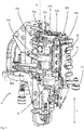
- FIG. 1 shows a forming station 4 of a forming device according to the invention (not shown in the entirety) in a closed state.
- This forming device 1 in this case has a first blow mold carrier part 44a and a second blow mold carrier part 44b. These two parts can be unfolded with respect to a here vertical pivot axis S, so as to be able to enter a plastic preform in a blow mold.
- At these two Blasform uman whatsoever 44a, 44b blow mold carrier shells 46a and 46b are arranged.
- these blow mold carrier shells can be fixed by means of a (quick) attachment mechanism. This quick-release mechanism can also be actuated automatically.
- blow-molding side parts 52a and 52b are arranged on the blow mold carrier shells 46a, 46b.
- the reference numerals 53a and 53b denote projections and gripping elements, respectively, on which the blow molds can be gripped and lifted by a change machine, such as a robot.
- Reference numerals 56 and 58 refer to two locking elements which serve to lock the blow mold.
- one locking element 58 is arranged on the blow mold carrier part 44a and the other locking element, which is pivotable with respect to a vertical axis, is arranged on the blow mold carrier part 44b.
- a cam roller 72 an opening and closing of this locking mechanism can be achieved.
- the reference numeral 12 denotes a support on which the blow mold is arranged.
- These carriers can, in particular in a working operation of the device, be raised and lowered via a drive, such as a motor or even a hydraulic or pneumatic drive (in particular for closing and opening the blow mold).
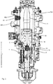
- FIG. 2 shows a sectional view of the forming station 1. It can be seen here again the blow molding 52b, which is arranged on a Blasformitatischale 46b and a blow mold carrier 44b. Reference numeral 40 denotes the attachment mechanism by means of which the blow mold carrier shell part is arranged on the blow mold carrier part 46b.
- a plastic preform can be expanded by applying compressed air to the plastic container. For this purpose, as mentioned above, compressed air is applied to the mouth of the plastic preform.
- the reference numeral 42 denotes a bottom part of the blow mold, which also limits the cavity 5.
- This bottom part 42 is arranged on an intermediate support 18, which also serves for adaptation to different Be 1969nisgattungen.
- the intermediate carrier 18 in turn is fastened to a fastening part 19 and this in turn via the fastening mechanism according to the invention on the support part 12th
- Reference numerals 8 and 9 schematically indicate connection devices which serve to supply a cooling medium.
- the corresponding fluid channels (not shown) initially extend radially inwards, then likewise in the vertical direction through the intermediate carrier 18 and thus reach the bottom part 42 in order to temper it.
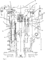
- the bottom part 42 (not shown) Temperiermediumkanäle on FIG. 3 shows a detailed representation of in Fig. 2 shown device.
- the reference numeral 6 refers in its entirety to the attachment mechanism.
- this attachment mechanism has a release element 62, which is movable in the vertical direction or in the longitudinal direction L. Also, the removal of the blow mold takes place in this direction.
- the terminal devices 8 and their connection elements 82 and 84 or 92 and 94 are separated from each other.
- the release element or adjusting element can be raised by applying compressed air, as explained in more detail below, in order to release the locking between the support 12 and the fastening part 19 and thus also the locking with the bottom part of the blow molding device.
- the fastening part 19 can be designed as a disk-like body, which is screwed for example to the intermediate carrier. This attachment part is in a change of the bottom part 42 together with the bottom part 42 and the intermediate carrier 18 decreased.
- Reference character R denotes a direction perpendicular to the longitudinal direction L. In this direction, for example, the side parts can be removed from their respective carriers.
- Reference numeral 96 refers to a spring element which biases the connecting element 92 upwards. In this way, a time-delayed release of the two connection devices 8, 9 can be achieved.
- the in the Fig. 3-5 Fixing mechanism shown in more detail can also be used in accordance with the attachment of the side parts to the carrier ie in particular the Blasformitatischalen.
- the attachment mechanisms 6 shown in each case are arranged in a position which is rotated relative to the position shown substantially at 90 °.
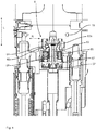
- FIG. 4 more precisely illustrates the operation of the attachment mechanism 6.
- the release member 62 is pressed in the normal operating state by a spring member 65 downward.
- the locking member 64 is pressed by the inclined surface 62 a to the outside and engages in this way in the fastener 66 a.
- the receiving space 67 is pressurized with compressed air, the actuator 62 will move upwards and in this way, the locking member 64 will withdraw and therefore no longer be in engagement with the fastener 66.
- the fastening part 19 and thus also the bottom part can be lifted here in the direction L upwards.
- the connection devices are separated, albeit delayed in time.
- the reference numeral 69 refers to a guide means which serves to guide the release member 62.
- This guide device 69 can engage in a bore of the release element 62, so that the release element 62 can slide relative to the guide means 69, but is guided by this guide means 69.
- the locking element in the in Fig. 4 shown direction R movable.
- FIG. 5 shows a further detail of the attachment mechanism. It can be seen here again the inclined surface 62a, which presses the locking member 64 radially outward depending on the position of the adjusting element or release element.
- the reference numeral 75 denotes a connection for the supply of compressed air. This connection is in fluid communication with the in FIG. 4 shown receiving space 57 so that a release of the fastening mechanism 6 can be achieved by applying compressed air.
- the spring element 65 is achieved, however, that in a normal state, the bottom part is locked to the carrier 12.
Description
Die vorliegende Erfindung bezieht sich auf eine Vorrichtung und ein Verfahren zum Umformen von Kunststoffvorformlingen zu Kunststoffbehältnissen. Derartige Vorrichtungen und Verfahren sind aus dem Stand der Technik seit langem bekannt.The present invention relates to an apparatus and a method for forming plastic preforms into plastic containers. Such devices and methods have been known for a long time from the prior art.
Dabei werden üblicherweise erwärmte Kunststoffvorformlinge einer Blasformeinrichtung, wie insbesondere einer Streckblasmaschine, zugeführt und von dieser zu Kunststoffbehältnissen expandiert.In this case, heated plastic preforms are usually supplied to a blow molding device, such as in particular a stretch blow molding machine, and expanded from this to plastic containers.
Diese Blasformmaschinen weisen dabei üblicherweise eine Vielzahl von Blasstationen auf, die wiederum mit Blasformen ausgestattet sind, in deren Innerem die Kunststoffvorformlinge durch Beaufschlagung mit Druckluft zu den Kunststoffbehältnissen und insbesondere zu Kunststoffflaschen umgeformt werden. Im Betrieb derartiger Vorrichtungen ist es oftmals jedoch erforderlich, die Blasformeinrichtungen auszuwechseln. Dies kann beispielsweise nötig sein, wenn von einer bestimmten Behältnisgattung auf eine andere Behältnisgattung bzw. Behältnisform umgestellt werden soll.These blow molding machines usually have a plurality of blowing stations, which in turn are equipped with blow molds, in the interior of which the plastic preforms are formed by applying compressed air to the plastic containers and in particular to plastic bottles. In the operation of such devices, however, it is often necessary to replace the blow molding equipment. This may be necessary, for example, if it is intended to switch from a specific type of container to a different type of container or container.
Diese Umstellung ist dabei im Stand der Technik ein relativ aufwendiger Prozess, da an jeder der einzelnen Umformungsstationen jeweils die Blasformen eingewechselt werden müssen. Dies erfolgt im Stand der Technik üblicherweise unter Verwendung von Werkzeugen, wie beispielsweise Schraubenziehern und dergleichen.This conversion is a relatively complex process in the prior art, since each of the individual transformation stations each blow molds must be changed. This is usually done in the art using tools such as screwdrivers and the like.
Die
Die
Aus der
Bei manchen Blasformeinrichtungen ist es im Rahmen des Herstellungsprozesses nötig oder vorteilhaft, wenn deren Wandungen temperiert, beispielsweise gekühlt werden. Zu diesem Zweck weisen die entsprechenden Blasformeinrichtungen bzw. deren Seitenteile oder deren Bodenteile Temperierkanäle auf, innerhalb derer ein Temperiermedium fließen kann. Diese Temperierkanäle werden dabei an eine Kühlmittelversorgung, beispielsweise an eine Wasserversorgung, angeschlossen und so kann im Arbeitsbetrieb die Temperierung erreicht bzw. aufrechterhalten werden.In some blow molding facilities, it is necessary or advantageous in the context of the manufacturing process, if the walls are tempered, for example, cooled. For this purpose, the corresponding blow molding devices or their side parts or their bottom parts on Temperierkanäle, within which a temperature control can flow. These tempering channels are connected to a coolant supply, for example to a water supply, and thus the temperature control can be achieved or maintained during operation.
Der vorliegenden Erfindung liegt die Aufgabe zugrunde, eine Vorrichtung und ein Verfahren zur Verfügung zu stellen, welche einen vergleichsweise schnellen Wechselvorgang der Blasformeinrichtung ermöglichen und welche bevorzugt auch ein zumindest teilautomatisches Wechseln von Blasformteilen ermöglichen sollen.The present invention has for its object to provide an apparatus and a method available which allow a comparatively quick change operation of the blow molding and which should preferably also allow at least semi-automatic change of blow moldings.
Diese Aufgaben werden erfindungsgemäß durch die Gegenstände der unabhängigen Ansprüche erreicht. Vorteilhafte Ausführungsformen und Weiterbildungen sind Gegenstand der Unteransprüche.These objects are achieved according to the invention by the subject matters of the independent claims. Advantageous embodiments and further developments are the subject of the dependent claims.
Eine erfindungsgemäße Vorrichtung zum Umformen von Kunststoffvorformlingen zu Kunststoffbehältnissen weist wenigstens eine Umformungsstation auf, welche wiederum eine Blasform aufweist, innerhalb derer die Kunststoffvorformlinge durch Beaufschlagung mit einem gasförmigen Medium expandierbar sind. Dabei weist die Blasform ein Bodenteil auf, welches lösbar (und zumindest mittelbar) an einem Träger angeordnet ist. Weiterhin weist die Vorrichtung einen Befestigungsmechanismus auf, um die Blasform und insbesondere das Bodenteil an diesem Träger zu befestigen.An inventive device for forming plastic preforms to plastic containers has at least one forming station, which in turn has a blow mold, within which the plastic preforms are expandable by exposure to a gaseous medium. In this case, the blow mold on a bottom part which is detachably (and at least indirectly) arranged on a support. Furthermore, the device has a fastening mechanism in order to fasten the blow mold and in particular the bottom part to this support.
Weiterhin weist die Vorrichtung, insbesondere die Umformungsstation wenigstens eine erste Anschlusseinrichtung auf, um der Vorrichtung, insbesondere der Umformungsstation und insbesondere auch dem Bodenteil ein fließfähiges Temperiermedium zuzuführen, wobei diese Zuführung des Temperiermediums über die Anschlusseinrichtung (insbesondere mittels einer durch die Anschlusseinrichtung tretenden Strömung) durch eine Entfernung bzw. eine Entfernungsbewegung des Bodenteils von dem Träger trennbar bzw. unterbrechbar ist.Furthermore, the device, in particular the forming station, has at least one first connection device in order to supply the device, in particular the forming station and in particular also the bottom part, with a flowable temperature control medium, this supply of the temperature control medium via the connection device (in particular by means of a flow passing through the connection device) a distance or a removal movement of the bottom part of the carrier is separable or interruptible.
Erfindungsgemäß weist dieser Befestigungsmechanismus ein in einer vorgegebenen geraden Richtung verschiebbares Löseelement auf, wobei durch eine Verschiebung dieses Löseelementes in eine erste vorgegebene Position die Befestigung des Bodenteils an dem Träger lösbar ist und durch eine Verschiebung dieses Löseelementes in eine zweite vorgegebene Position das Bodenteil an dem Träger befestigbar ist.According to the invention, this fastening mechanism has a releasable in a predetermined straight direction release element, wherein the attachment of the bottom part to the carrier is releasable by a displacement of this release element in a first predetermined position and by displacement of this release element in a second predetermined position, the bottom part of the carrier is fastened.
Es wird daher vorgeschlagen, dass die Befestigung des Bodenteils bzw. ein Lösen dieser Befestigung durch eine geradlinige Bewegung dieses genannten Löseelementes erreicht wird. Diese besagte geradlinige Bewegung kann auf relativ einfache Weise etwa durch pneumatische Mittel erreicht werden. Auf diese Weise kann ein automatisiertes Entfernen des Bodenteils von der Blasform erreicht werden. Vorteilhaft handelt es sich bei dem Löseelement um ein Stellelement, welches zumindest mittelbar eine Arretierung der Befestigung bzw. ein Lösen dieser Arretierung bewirkt. Dabei ist es möglich, dass durch dieses Löseelement bzw. Stellelement wiederum ein weiteres Element betätigt bzw. bewegt wird, und durch diese Betätigung die Arretierung bzw. Lösung der Arretierung erreicht wird. Bevorzugt kann daher das Stellelement zum Arretieren in eine erste Richtung bewegt werden und zum Lösen der Arretierung in eine zweite Richtung, welche der ersten Richtung entgegengesetzt ist.It is therefore proposed that the attachment of the bottom part or a release of this attachment is achieved by a rectilinear movement of said release element. This said linear movement can be achieved in a relatively simple manner, for example by pneumatic means. In this way, an automated removal of the bottom part of the blow mold can be achieved. Advantageously, the release element is an adjusting element, which at least indirectly causes a locking of the attachment or a release of this locking. It is possible that in turn by this release element or actuator another element is actuated or moved, and by this operation, the locking or solution of the lock is achieved. Preferably, therefore, the actuator can be moved to lock in a first direction and to release the locking in a second direction, which is opposite to the first direction.
Wie oben erwähnt, ist es bei der Fertigung der Behältnisse teilweise erforderlich, dass die jeweiligen Blasformen bzw. auch deren Bodenteile temperiert und insbesondere gekühlt werden. Zu diesem Zweck dient die hier beschriebene Anschlusseinrichtung, mittels derer letztlich das Bodenteil an eine Temperiermittel- und insbesondere eine Wasserversorgung angeschlossen werden kann. Durch eine Entfernung des Bodenteils von dem Träger kann damit (insbesondere im Wesentlichen gleichzeitig) auch die Temperiermittelversorgung unterbrochen werden.As mentioned above, it is sometimes necessary in the manufacture of the containers that the respective blow molds or their bottom parts are tempered and, in particular, cooled. For this purpose, the connection device described here, by means of which ultimately the bottom part can be connected to a Temperiermittel- and in particular a water supply. By removing the bottom part from the carrier, the temperature control medium supply can thus be interrupted (in particular substantially simultaneously).
Eine weitere erfindungsgemäße Vorrichtung zum Umformen von Kunststoffvorformlingen zu Kunststoffbehältnissen mit wenigstens einer Umformungsstation, welche eine Blasform aufweist, innerhalb derer die Kunststoffvorformlinge durch Beaufschlagung mit einem gasförmigen Medium expandierbar sind, wobei die Blasform wenigstens ein Seitenteil aufweist, welches lösbar an einem Träger angeordnet ist und mit einem Befestigungsmechanismus, um das Seitenteil an dem Träger zu befestigen.A further inventive device for forming plastic preforms into plastic containers having at least one forming station, which has a blow-mold, within which the plastic preforms are expandable by exposure to a gaseous medium, wherein the blow mold has at least one side part which is detachably arranged on a support and with a fixing mechanism for fixing the side member to the carrier.
Erfindungsgemäß weist dieser Befestigungsmechanismus ein in einer vorgegebenen geraden Richtung verschiebbares Löseelement auf, und durch eine Verschiebung dieses Löseelements in eine erste vorgegebene Position ist die Befestigung des Seitenteils an dem Träger lösbar und durch eine Verschiebung dieses Löseelements in eine zweite vorgegebene Position ist das Seitenteil an dem Träger befestigbar.According to the invention, this fastening mechanism has a releasable in a predetermined straight direction release element, and by a displacement of this release element in a first predetermined position, the attachment of the side part to the carrier is releasable and by a displacement of this release element in a second predetermined position, the side part of the Carrier attachable.
Es wird also im Rahmen der Erfindung für die Befestigung des Seitenteils bzw. der Seitenteile der gleiche Mechanismus vorgeschlagen wie für das Bodenteil. Im Rahmen der nachfolgenden Figurenbeschreibung wird der Befestigungsmechanismus des Bodenteils beschrieben. Ein entsprechender Befestigungsmechanismus wird auch zur Befestigung der Seitenteile verwendet. Dieser Befestigungsmechanismus ist jedoch im Einbauzustand gegenüber dem Befestigungsmechanismus des Bodenteils im Wesentlichen um 90° gedreht. Bevorzugt sind zwei derartige Befestigungsmechanismen zum Halten der Seitenteile vorgesehen (pro Seitenteil ein Befestigungsmechanismus).It is therefore proposed in the context of the invention for the attachment of the side part or the side parts of the same mechanism as for the bottom part. In the context of the following description of the figures, the attachment mechanism of the bottom part will be described. A corresponding attachment mechanism is also used to attach the side panels. However, this mounting mechanism is rotated in the installed state relative to the attachment mechanism of the bottom part substantially at 90 °. Preferably, two such fastening mechanisms for holding the side parts are provided (per side part, a fastening mechanism).
Der hier beschriebene Befestigungsmechanismus bietet den Vorteil, dass er eine automatische Lösung und/oder Befestigung des Seitenteils bzw. Bodenteils von bzw. an dem Träger ermöglicht. Bevorzugt handelt es sich bei dem Träger des Seitenteils um eine sog. Blasformträgerschale. Bei einem Einwechseln des Seitenteils kann diese Blasformträgerschale an einem Blasformträger befestigt bleiben und das Seitenteil wird von der Blasformträgerschale gelöst. Damit ist dieser Befestigungsmechanismus bevorzugt zwischen der Blasformträgerschale und dem Seitenteil ausgebildet.The fastening mechanism described here has the advantage that it allows an automatic solution and / or attachment of the side part or bottom part of or on the carrier. Preferably, the carrier of the side part is a so-called. Blasformträgerschale. When replacing the side part, this Blasformträgerschale remain attached to a blow mold and the side part is released from the Blasformträgerschale. Thus, this attachment mechanism is preferably formed between the Blasformträgerschale and the side part.
Es wäre jedoch auch denkbar, dass dieser Befestigungsmechanismus zwischen dem Blasformträger und der Blasformträgerschale ausgebildet ist oder zwischen dem Blasformträger und dem Seitenteil. Bevorzugt ist das Seitenteil unmittelbar an der Blasformträgerschale angeordnet.However, it would also be conceivable that this attachment mechanism is formed between the blow mold carrier and the blow mold carrier shell or between the blow mold carrier and the side part. Preferably, the side part is arranged directly on the Blasformträgerschale.
Bevorzugt weist dabei die Umformungsstation wenigstens eine erste Anschlusseinrichtung auf, um der Umformungsstation und insbesondere dem Seitenteil ein fließfähiges Temperiermedium zuzuführen, und diese Zuführung des Temperiermediums ist über die Anschlusseinrichtung durch eine Entfernung des Seitenteils von dem Träger trennbar. Es wird daher auch für das Seitenteil vorgeschlagen, dass dieses Temperierkanäle aufweist, durch welche ein Temperiermedium fließen kann, um so dieses Seitenteil zu temperieren, etwa zu kühlen.In this case, the forming station preferably has at least one first connection device in order to supply a flowable tempering medium to the transformation station and in particular to the side part, and this supply of the tempering medium can be separated from the carrier by means of the connection device by removing the side part. It is therefore also proposed for the side part that this has tempering, through which a temperature control can flow, so as to temper this side part, such as to cool.
Im Folgenden wird die Ausgestaltung dieser Temperierung und auch des Befestigungsmechanismus überwiegend unter Bezugnahme auf das Bodenteil beschrieben. Es wird jedoch darauf hingewiesen, dass diese Ausgestaltungen entsprechend auch auf die Befestigung des Seitenteils anwendbar sind.In the following, the configuration of this temperature and also of the fastening mechanism will be described mainly with reference to the bottom part. However, it should be noted that these embodiments are also applicable to the attachment of the side part.
Bei einer vorteilhaften Ausführungsform ist das Bodenteil über wenigstens einen Zwischenträger an dem genannten Träger angeordnet. Dabei ist es möglich, dass an dem Bodenteil der Zwischenträger angeordnet ist und dieser beispielsweise auch als Abstandshalter fungiert. Auch kann bevorzugt an diesem Zwischenträger, ggf. jedoch auch an dem Bodenteil selbst, ein Befestigungsteil angeordnet sein und an diesem Befestigungsteil wiederum ein Teil des Befestigungsmechanismus.In an advantageous embodiment, the bottom part is arranged on at least one intermediate carrier on said carrier. It is possible that the intermediate part is arranged on the bottom part and this acts, for example, as a spacer. It is also possible for a fastening part to be arranged preferably on this intermediate carrier, but possibly also on the bottom part itself, and in turn a part of the fastening mechanism on this fastening part.
Bei einer weiteren vorteilhaften Ausführungsform weist, wie oben ausgeführt die Vorrichtung bzw. die Umformungsstation auch zwei Seitenteile auf, welche bevorzugt gemeinsam mit dem Bodenteil den Hohlraum begrenzen, innerhalb dessen die Kunststoffvorformlinge zu den Kunststoffbehältnissen umgeformt werden.In a further advantageous embodiment, as stated above, the device or the forming station also has two side parts, which preferably together with the bottom part define the cavity within which the plastic preforms are formed into the plastic containers.
Vorteilhaft sind auch die oben erwähnten Seitenteile der Blasformeinrichtung jeweils an einem Blasformträger angeordnet. Bevorzugt sind dabei die Seitenteile an Blasformträgerschalen angeordnet und diese Blasformträgerschalen wiederum an Blasformträgern. Vorteilhaft sind die Blasformträger, an denen die Seitenteile angeordnet sind, um eine Schwenkachse, insbesondere eine gemeinsame Schwenkachse schwenkbar, um auf diese Weise die Blasformeinrichtung zu öffnen und zu schließen. Vorteilhaft verläuft dabei diese Schwenkachse parallel zu der Längsrichtung eines Kunststoffvorformlings bzw. auch eines hieraus herzustellenden Kunststoffbehältnisses.Advantageously, the above-mentioned side parts of the blow molding device are each arranged on a blow mold carrier. Preferably, the side parts are arranged on Blasformträgerschalen and this Blasformträgerschalen turn to Blasformträgern. Advantageously, the blow mold carriers, on which the side parts are arranged, are pivotable about a pivot axis, in particular a common pivot axis, in order to open and close the blow molding device in this way. Advantageously, this pivot axis runs parallel to the longitudinal direction of a plastic preform or even a plastic container to be produced therefrom.
Vorteilhaft weist die Vorrichtung weiterhin eine Beaufschlagungseinrichtung auf, um die Kunststoffvorformlinge mit einem fließfähigen und insbesondere mit einem gasförmigen Medium (insbesondere mit Druckluft) zu beaufschlagen. Bei dieser Beaufschlagungseinrichtung handelt es sich vorteilhaft um eine Blasdüse, welche an den Kunststoffvorformling angesetzt werden kann, um diesen so zu expandieren. Vorteilhaft ist dabei die Beaufschlagungseinrichtung mittels einer Antriebseinrichtung auf den Kunststoffvorformling zustellbar. Bei einer weiteren vorteilhaften Ausführung weist die Vorrichtung auch ein stangenförmiges Element auf, welches in das Innere der Kunststoffvorformlinge einführbar ist, um diese in ihrer Längsrichtung zu dehnen. Damit weist die Vorrichtung bevorzugt eine sogenannte Reckstange auf und es handelt sich bei der Vorrichtung vorteilhaft um eine Streckblasmaschine.Advantageously, the device further comprises a loading device in order to pressurize the plastic preforms with a flowable and in particular with a gaseous medium (in particular with compressed air). This loading device is advantageously a blowing nozzle, which can be attached to the plastic preform in order to expand it. Advantageously, the loading device can be delivered to the plastic preform by means of a drive device. In a further advantageous embodiment, the device also has a rod-shaped element which can be inserted into the interior of the plastic preforms in order to stretch them in their longitudinal direction. Thus, the device preferably has a so-called stretch rod and the device is advantageously a stretch blow molding machine.
Bei einer weiteren vorteilhaften Ausführungsform können die Seitenteile auch zum Schließen der Blasform in Bereiche des Bodenteils eingreifen. Bei einer weiteren vorteilhaften Ausführungsform weist die Vorrichtung eine Vielzahl von Umformungsstationen auf, die besonders bevorzugt an einem gemeinsamen Träger angeordnet sind. Dabei handelt es sich bei diesem Träger insbesondere um einen drehbaren Träger wie ein sog. Blasrad.In a further advantageous embodiment, the side parts can also engage for closing the blow mold in areas of the bottom part. In a further advantageous embodiment, the device has a plurality of forming stations, which are particularly preferably arranged on a common carrier. In particular, this carrier is a rotatable carrier such as a so-called blowing wheel.
Vorteilhaft ist zwischen den Blasformträgerteilen und den Blasformteilen bzw. Seitenteilen wenigstens ein mit einem gasförmigen Medium beaufschlagbarer Raum ausgebildet. Auf diese Weise kann insbesondere ein Druckkissen ausgebildet werden, mittels dessen ein Blasformteil während des Expansionsvorganges auf das andere Blasformteil zugestellt werden kann. Vorteilhaft weist damit wenigstens ein Blasformteil gegenüber demjenigen Blasformträgerteil, an dem es angeordnet ist, ein gewisses mechanisches Spiel in einer Richtung auf, welche senkrecht zu einer Ebene steht, welche in einem geschlossenen Zustand der Blasform zwischen den beiden Blasformteilen definiert wird.Advantageously, at least one space which can be acted upon by a gaseous medium is formed between the blow mold carrier parts and the blow mold parts or side parts. In this way, in particular, a pressure pad can be formed, by means of which a blow molded part can be delivered to the other blow molded part during the expansion process. Advantageously, therefore, at least one blow molding with respect to that Blasformträgerteil on which it is arranged, a certain mechanical play in a direction which is perpendicular to a plane which is defined in a closed state of the blow mold between the two blow moldings.
Bei einer weiteren vorteilhaften Ausführungsform ist das oben erwähnte Lösungselement automatisch betätigbar bzw. bewegbar. Vorteilhaft ist dieses Löseelement durch ein Fließmittel betätigbar, also insbesondere hydraulisch oder pneumatisch betätigbar. Es wäre jedoch auch denkbar, dass das Löseelement durch eine Magnetkraft betätigt wird. So wäre es denkbar, dass eine Robotereinrichtung vorgesehen ist, welche einen derartigen Wechsel des Bodenteils und/oder der Seitenteile automatisch durchführt. Dazu könnte zunächst der Befestigungsmechanismus gelöst und anschließend das betreffende Seitenteil entnommen werden. Vorteilhaft ist das Löseelement für einen Benutzer bzw. Bediener nicht zugänglich, ohne dass hierzu der Befestigungsmechanismus gelöst und das Blasformteil abgenommen wird, beispielsweise indem es innerhalb des erwähnten Trägers angeordnet ist.In a further advantageous embodiment, the above-mentioned solution element is automatically actuated or movable. Advantageously, this release element can be actuated by a flow agent, ie in particular hydraulically or pneumatically actuated. However, it would also be conceivable that the release element is actuated by a magnetic force. So it would be conceivable that a robot device is provided which such a change of Floor part and / or the side parts automatically performs. For this purpose, first the attachment mechanism could be released and then the relevant side part can be removed. Advantageously, the release element is inaccessible to a user or operator without, for this purpose, disengaging the attachment mechanism and removing the blow molding part, for example by placing it within the mentioned carrier.
Bevorzugt weist die erfindungsgemäße Vorrichtung die beschriebenen Befestigungsmechanismen sowohl für das oder die Seitenteile der Blasformeinrichtung als auch für das Bodenteil auf. So wäre es möglich, dass automatisiert sowohl die Befestigungen der Seitenteile als auch des Bodenteils gelöst oder hergestellt werden. Weiterhin wäre es denkbar, dass, insbesondere nach einem Lösen der jeweiligen Befestigungsmechanismen die Blasformeinrichtung in ihrer Gesamtheit von der Umformungsstation entnommen wird. Dabei wäre es insbesondere denkbar, dass weitere Arretiermechanismen vorgesehen sind, welche die Seitenteile und das Bodenteil der Blasform, insbesondere für einen Montage- und einen Demontagevorgang aneinander befestigen, damit die Blasformeinrichtung in einem zusammengesetzten Zustand montiert oder demontiert werden kann.The device according to the invention preferably has the fastening mechanisms described for the one or the side parts of the blow molding device as well as for the bottom part. So it would be possible that automatically both the fasteners of the side parts and the bottom part are solved or manufactured. Furthermore, it would be conceivable that, in particular after a release of the respective fastening mechanisms, the blow molding device is removed in its entirety from the forming station. It would be particularly conceivable that further locking mechanisms are provided which fasten the side parts and the bottom part of the blow mold, in particular for an assembly and disassembly process to each other so that the blow mold can be assembled or disassembled in an assembled state.
Weiterhinkann beispielsweise der Träger eine Kontaktfläche aufweisen, welche in einem montierten Zustand an einem zumindest mittelbar an dem Bodenteil (bzw. dem Seitenteil) befestigten Befestigungselement (bzw. einer entsprechenden Kontaktfläche dieses Befestigungselements anliegt und ein erster Bestandteil der Befestigungseinrichtung kann innerhalb dieser Kontaktfläche angeordnet sein. Bevorzugt ist in einem arretierten Zustand des Bodenteils bzw. des Seitenteils an dem Träger die Befestigungseinrichtung in Umfangsrichtung vollständig von Bereichen bzw. Material des Trägers umgeben. Vorteilhaft weist das Löseelement einen kreisförmigen Querschnitt auf.Furthermore, for example, the carrier may have a contact surface which, in an assembled state, abuts against a fastening element (or a corresponding contact surface of this fastening element fastened at least indirectly to the bottom part (or the side part) and a first component of the fastening device can be arranged within this contact surface. In a locked state of the bottom part or of the side part on the carrier, the fastening device is preferably completely surrounded by regions or material of the carrier in the circumferential direction.
Bei einer weiteren vorteilhaften Ausführungsform weist die Vorrichtung eine Führungseinrichtung auf, welche das Löseelement führt. Dabei kann beispielsweise ein Hülsenkörper vorgesehen sein, innerhalb dessen das Löseelement verschiebbar gelagert ist. Umgekehrt kann jedoch (bevorzugt) das Führungselement auch als stangenartiger Körper ausgebildet sein, der wiederum in das Löseelement eingreift und so eine Führung des Löseelementes bewirkt.In a further advantageous embodiment, the device has a guide device which guides the release element. In this case, for example, a sleeve body may be provided, within which the release element is displaceably mounted. Conversely, however, (preferably) the guide element can also be designed as a rod-like body, which in turn engages in the release element and thus causes a guide of the release element.
Vorteilhaft ist das Löseelement (welches zum Befestigen des Bodenteils dient) in der Längsrichtung der zu expandierenden Kunststoffvorformlinge betätigbar. Vorteilhaft handelt es sich hierbei um die gleiche Richtung, in der auch die oben erwähnte Reckstange in das Innere der Kunststoffvorformlinge eingeführt wird. Vorteilhaft ist das Löseelement (welches zum Befestigen des Seitenteils dient) im Wesentlichen senkrecht zu der Längsrichtung der zu expandierenden Kunststoffvorformlinge betätigbar. Im Falle der Befestigung der Seitenteile ist bevorzugt das Löseelement verschieblich an der Blasformträgerschale angeordnet.Advantageously, the release element (which serves to fasten the bottom part) in the longitudinal direction of the plastic preforms to be expanded actuated. It is advantageous this is the same direction in which the above-mentioned stretch rod is introduced into the interior of the plastic preforms. Advantageously, the release element (which serves to fasten the side part) can be actuated substantially perpendicular to the longitudinal direction of the plastic preforms to be expanded. In the case of attachment of the side parts, the release element is preferably arranged displaceably on the blow mold carrier shell.
Vorteilhaft kann durch eine Entfernung des Bodenteils bzw. des Seitenteils von dem jeweiligen Träger (im Falle des Seitenteils insbesondere der Blasformträgerschale) auch dieser Anschluss für das Temperiermedium bzw. das Kühlmittel getrennt werden. Bevorzugt kann in dem gleichen Arbeitsschritt, wenn auch nicht notwendig zeitgleich, sowohl das Bodenteil bzw. das Seitenteil von dem Träger gelöst als auch die Versorgung mit dem Temperiermedium unterbrochen werden. So ist bevorzugt möglich, dass beispielsweise das Bodenteil - ggf. gemeinsam mit einem an dem Bodenteil angeordneten Zwischenträger und/oder einem Befestigungselement - von dem Träger abgehoben und damit getrennt wird und durch den gleichen Vorgang auch die Verbindung(en) für das Temperiermedium unterbrochen werden. Bevorzugt können die Verbindungen für das Temperiermedium durch eine Zustellbewegung des Bodenteils auf den Träger zu hergestellt werden.Advantageously, by a removal of the bottom part or the side part of the respective carrier (in the case of the side part in particular the Blasformträgerschale) and this connection for the temperature control or the coolant are separated. Preferably, although not necessarily at the same time, both the bottom part and the side part are released from the carrier in the same step and the supply of the temperature control medium are interrupted. Thus, it is preferably possible that, for example, the bottom part - possibly together with an arranged on the bottom part intermediate carrier and / or a fastener - lifted from the carrier and thus separated and are interrupted by the same process, the compound (s) for the temperature control , Preferably, the compounds for the temperature control can be prepared by a feed movement of the bottom part of the carrier.
Bei einer weiteren vorteilhaften Ausführungsform ist das Bodenteil bzw. das Seitenteil nach einem Lösen des Befestigungsmechanismus durch eine Bewegung in einer geraden Richtung entfernbar. Vorteilhaft handelt es sich hierbei im Falle des Bodenteils bzw. des Seitenteils um die gleiche Richtung, in der auch das Löseelement bewegbar ist. Im Falle des Bodenteils kann es sich hierbei um eine Richtung handeln, die parallel zu der Längsrichtung der Kunststoffvorformlinge ist, im Falle des Seitenteils um eine Richtung, welche im Wesentlichen senkrecht zu der Längsrichtung der Kunststoffvorformlinge steht. Bevorzugt sind bewegliche Elemente der jeweiligen Befestigungsmechanismen wie insbesondere das Löseelement und/oder das Arretierelement an den jeweiligen Trägern angeordnet. Dies hat den Vorteil, dass diese Elemente bei einem Auswechseln der Blasformeinrichtungen an der Maschine verbleiben.In a further advantageous embodiment, the bottom part or the side part is removable after a release of the fastening mechanism by a movement in a straight direction. In the case of the bottom part or the side part, this is advantageously the same direction in which the release element is also movable. In the case of the bottom part, this may be a direction that is parallel to the longitudinal direction of the plastic preforms, in the case of the side part about a direction which is substantially perpendicular to the longitudinal direction of the plastic preforms. Preferably, movable elements of the respective attachment mechanisms, in particular the release element and / or the locking element, are arranged on the respective carriers. This has the advantage that these elements remain in the replacement of the blow molding on the machine.
Bei einer weiteren vorteilhaften Ausführungsform weist die erste Anschlusseinrichtung ein erstes Anschlusselement auf sowie ein zweites Anschlusselement, welche durch eine Relativbewegung des einen Anschlusselementes gegenüber dem anderen Anschlusselement in einer geraden Richtung miteinander koppelbar sind, um der Umformungsstation und insbesondere dem Bodenteil bzw. dem Seitenteil der Blasformeinrichtung das fließfähige Temperiermedium zuzuführen. Durch diese An- und/oder Entkoppelbarkeit der Anschlusseinrichtungen ist es daher möglich, dass durch die gleiche Bewegung, nämlich eine Entfernungsbewegung der Blasform von dem Träger, auch die Anschlüsse getrennt werden und umgekehrt bei einer Zuführung des Blasformteils auf den Träger auch die Anschlusseinrichtungen bzw. deren Anschlusselemente miteinander verbunden werden.In a further advantageous embodiment, the first connection device has a first connection element and a second connection element, which can be coupled to one another in a straight direction by a relative movement of the one connection element relative to the other connection element, in particular around the conversion station to supply the flowable tempering medium to the bottom part or the side part of the blow molding device. By this arrival and / or decoupling of the connection devices, it is therefore possible that by the same movement, namely a removal movement of the blow mold from the carrier, the terminals are separated and vice versa in a supply of the blow molded on the support and the connection devices whose connection elements are connected together.
Vorteilhaft weist wenigstens ein Anschlusselement und insbesondere ein Anschlusselement, welches zumindest mittelbar an dem Blasformteil angeordnet ist, eine Ventileinrichtung auf, welches bei einer Trennung der Anschlusselemente schließt, so dass nach dem Trennvorgang kein Temperiermedium aus dem Bodenteil strömen kann.Advantageously, at least one connection element and in particular a connection element, which is arranged at least indirectly on the blow molding, a valve device which closes at a separation of the connection elements, so that after the separation process no temperature control medium can flow from the bottom part.
Mit anderen Worten kann durch eine Relativbewegung der Anschlusselemente bezüglich einander eine Fluidverbindung zwischen einer Temperiermittelversorgung und dem Bodenteil bzw. den Seitenteilen hergestellt bzw. auch unterbrochen werden.In other words, by means of a relative movement of the connection elements with respect to each other, a fluid connection between a temperature control medium supply and the bottom part or the side parts can be produced or interrupted.
Bei einer weiteren vorteilhaften Ausführungsform entspricht die erwähnte gerade Richtung auch der Entfernungsrichtung des Bodenteils bzw. des Seitenteils und/oder der Bewegungsrichtung des Löseelementes.In a further advantageous embodiment, the mentioned straight direction also corresponds to the removal direction of the bottom part or the side part and / or the direction of movement of the release element.
Bei einer weiteren vorteilhaften Ausführungsform weist das Löseelement einen stangenförmigen Körper auf und/oder einen Körper, der sich in der oben erwähnten Bewegungsrichtung des Löseelementes erstreckt.In a further advantageous embodiment, the release element has a rod-shaped body and / or a body which extends in the above-mentioned movement direction of the release element.
Vorteilhaft erstreckt sich auch wenigstens ein Anschlusselement und besonders bevorzugt erstrecken sich beide Anschlusselemente in der oben erwähnten Richtung, in der auch das Löseelement bewegbar ist. Falls also, wie im Stand der Technik häufig der Fall, Kunststoffvorformlinge in einem stehenden Zustand in die Blasform eingebracht werden, wobei ihre Mündung nach oben ausgerichtet ist, erstrecken sich vorteilhaft (im Falle des Bodenteils) auch die Anschlusselemente in der Längsrichtung der Kunststoffvorformlinge und (im Falle des oder der Seitenteile) im Wesentlichen senkrecht zu dieser Längsrichtung. Bevorzugt sind die Anschlusselemente als Stecker und Kupplung ausgeführt.Advantageously, at least one connecting element also extends and particularly preferably both connecting elements extend in the above-mentioned direction, in which the release element is also movable. Thus, if, as is often the case in the prior art, plastic preforms are introduced into the blow mold in a stationary state with their mouth oriented upward, the connecting elements advantageously also extend (in the case of the bottom part) in the longitudinal direction of the plastic preforms and ( in the case of the or the side parts) substantially perpendicular to this longitudinal direction. Preferably, the connection elements are designed as a plug and coupling.
Auf diese Weise ist ein Wechsel des Bodenteils und/oder des Seitenteils automatisch durchführbar. So kann beispielsweise mittels eines Wechselroboters das Bodenteil ergriffen werden und nach Lösen des Befestigungsmechanismus von dem Träger entnommen werden. Bevorzugt kann in dem gleichen Arbeitsgang auch die Temperiermittelverbindung gelöst werden. Durch die oben beschriebenen Vorgehensweisen ist eine automatische Betätigung des Löseelements möglich, insbesondere im Rahmen eines Wechselprozesses der Blasform. Dabei kann, wie oben erwähnt, das Löseelement automatisch bewegt werden.In this way, a change of the bottom part and / or the side part is automatically carried out. Thus, for example, by means of an alternating robot, the bottom part can be taken and removed after releasing the fastening mechanism of the carrier. Preferably, in the same operation, the Temperiermittelverbindung be solved. By the procedures described above, an automatic actuation of the release element is possible, in particular in the context of a change process of the blow mold. In this case, as mentioned above, the release element can be moved automatically.
Bei einer weiteren vorteilhaften Ausführungsform weist die Vorrichtung eine zweite Anschlusseinrichtung auf, um das Temperiermedium von dem Bodenteil abzuführen. Auf diese Weise kann das Bodenteil in einen Temperierkreislauf eingebunden werden. Vorteilhaft ist auch diese Zuführung durch eine Entfernung des Bodenteils trennbar. Dabei ist es auch hier bevorzugt, dass die zweite Anschlusseinrichtung zwei Anschlusselemente aufweist, welche durch eine Relativbewegung und insbesondere eine Relativbewegung in der oben beschriebenen Richtung miteinander verbindbar oder lösbar sind. Auf diese Weise ist es auch möglich, das Bodenteil automatisch in einen Temperierkreislauf einzubinden.In a further advantageous embodiment, the device has a second connection device in order to discharge the temperature control medium from the bottom part. In this way, the bottom part can be integrated into a temperature control circuit. Advantageously, this feed is separable by a removal of the bottom part. It is also preferred here for the second connection device to have two connection elements which can be connected to one another or released by a relative movement and in particular a relative movement in the direction described above. In this way it is also possible to automatically integrate the bottom part in a tempering circuit.
Bei einer weiteren vorteilhaften Ausführungsform sind die Anschlusseinrichtungen und/oder Anschlusselemente in der oben besagten Richtung, d.h. derjenigen Richtung, in der auch das Bodenteil von dem Träger abgenommen wird, versetzt zueinander angeordnet. Auf diese Weise ist es möglich, dass bei einer Montage des Bodenteils an dem Träger zunächst eine Anschlusseinrichtung betätigt bzw. angeschlossen wird und anschließend die andere. Auf diese Weise ist ein zeitlich versetztes Anschließen der beiden Anschlusseinrichtungen bzw. der jeweiligen Anschlusselemente an einen Temperierkreislauf möglich.In a further advantageous embodiment, the connection devices and / or connection elements are in the above-mentioned direction, i. that direction in which the bottom part is removed from the carrier, offset from each other. In this way it is possible that when a mounting of the bottom part of the carrier first a connection device is actuated or connected and then the other. In this way, a temporally offset connection of the two connection devices or the respective connection elements to a temperature control circuit is possible.
Durch eine federbelastete Anordnung des einen Anschlusselementes kann erreicht werden, dass bei einer Zustellung des Bodenteils an den Träger zunächst das jeweilige Anschlusselement bewegt wird, bevor es mit dem anderen Anschlusselement zusammenwirkt bzw. mit diesem zusammengeschlossen wird. Auch kann durch diese federbelastete Anordnung des Anschlusselements eine selbsttätige Rückstellung dieses Anschlusselements in eine vorgegebene Ausgangsposition erreicht werden.By a spring-loaded arrangement of a connecting element can be achieved that at a delivery of the bottom part of the carrier first the respective connection element is moved before it cooperates with the other connection element or is joined together with this. Also, by this spring-loaded arrangement of the connection element, an automatic reset of this connection element can be achieved in a predetermined starting position.
Bei einer weiteren vorteilhaften Ausführungsform weist der Befestigungsmechanismus ein Arretierelement auf, welches durch eine Bewegung des Löseelementes in der Richtung zwischen wenigstens zwei Positionen bewegbar ist, wobei in einer dieser Positionen eine Arretierung zwischen dem Träger und dem Bodenteil bzw. dem Seitenteil hergestellt ist und in der anderen Position eine Arretierung zwischen dem Träger und dem Bodenteil bzw. dem Träger und dem Seitenteil gelöst ist.In a further advantageous embodiment, the fastening mechanism has a locking element, which by movement of the release element in the direction between at least two positions is movable, wherein in one of these positions, a locking between the carrier and the bottom part or the side part is made and in the other position, a detent between the carrier and the bottom part or the carrier and the side part is released.
So wäre es beispielsweise möglich, dass das Löseelement in der Längsrichtung der Kunststoffvorformlinge bewegt wird und hierdurch eine Querbewegung des Arretierelementes ausgelöst wird. Bevorzugt weist das Löseelement einen sich erweiternden Abschnitt, beispielweise einen sich kegelförmig erweiternden Abschnitt auf bzw. eine Schrägfläche, welche bevorzugt in Kontakt mit dem Arretierelement steht. Durch eine Bewegung des Löseelementes in der oben beschriebenen Richtung kann auf diese Weise auch eine Bewegung des Arretierelementes insbesondere in einer hierzu senkrechten oder schrägen Richtung erreicht werden.Thus, it would be possible, for example, that the release element is moved in the longitudinal direction of the plastic preforms and thereby a transverse movement of the locking element is triggered. Preferably, the release element has a widening portion, for example, a conically widening portion or an inclined surface, which is preferably in contact with the locking element. By a movement of the release element in the direction described above, a movement of the locking element can be achieved in this way, in particular in a direction perpendicular thereto or oblique direction.
Durch diese Bewegung des Arretierelementes ist es möglich, dass in Folge einer Bewegung des Löseelementes das Arretierelement in ein weiteres Element der Befestigungseinrichtung eingreift. Vorteilhaft sind das Arretierelement und besonders bevorzugt auch das Löseelement an dem Träger angeordnet. Ein entsprechender Hinterschnitt bzw. eine Eingriffsausnehmung, in welche das Arretierelement eingreifen kann, ist besonders bevorzugt zumindest mittelbar an dem Bodenteil, beispielsweise an dem Zwischenträger oder einem an dem Zwischenträger fest angeordneten Befestigungskörper angeordnet.By this movement of the locking element, it is possible that engages in a further element of the fastening device as a result of movement of the release element, the locking element. Advantageously, the locking element and particularly preferably the release element are arranged on the carrier. A corresponding undercut or an engagement recess into which the locking element can engage is particularly preferably arranged at least indirectly on the base part, for example on the intermediate carrier or on a fastening body fixedly arranged on the intermediate carrier.
Bei einer weiteren vorteilhaften Ausführungsform ist das Arretierelement durch die Bewegung des Löseelementes in einer von der Bewegungsrichtung des Löseelementes abweichenden Richtung bewegbar.In a further advantageous embodiment, the locking element is movable by the movement of the release element in a deviating from the direction of movement of the release element direction.
Wie erwähnt, ist bevorzugt an dem Löseelement eine Schrägfläche, d.h. eine bezüglich der Längsrichtung ausgebildete Schrägfläche angeordnet, welche eine Kontaktfläche mit dem Arretierelement bildet.As mentioned, it is preferable to have an inclined surface on the release element, i. arranged with respect to the longitudinal direction inclined surface, which forms a contact surface with the locking element.
Bei einer weiteren bevorzugten Ausführungsform ist es auch möglich, dass mehrere der beschriebenen Arretierelemente vorgesehen sind. Dabei ist es möglich, dass durch eine Bewegung des Löseelementes mehrere Arretierelemente gleichzeitig bewegt werden und beispielsweise in entsprechende Ausnehmungen eines Halteelementes eingeführt werden.In a further preferred embodiment, it is also possible that a plurality of the described locking elements are provided. It is possible that a plurality of locking elements are moved simultaneously by a movement of the release element and introduced, for example, in corresponding recesses of a holding element.
Auch könnte es sich bei dem Arretierelement um ein ringförmiges Element handeln, welches das Löseelement und insbesondere die Schrägfläche dieses Löseelements in dessen Umfangsrichtung umgibt. Bevorzugt ist das Arretierelement in einer bezüglich der Längsrichtung des Löseelements radial verlaufenden Richtung bewegbar. Bevorzugt kann das Arretierelement einen Abschnitt eines weiteren Befestigungselements und insbesondere eines an mittelbar an dem Bodenteil angeordneten Befestigungselements hintergreifen.The locking element could also be an annular element which surrounds the release element and in particular the oblique surface of this release element in its circumferential direction. Preferably, the locking element is movable in a radial direction with respect to the longitudinal direction of the release element. Preferably, the locking element can engage behind a section of a further fastening element and in particular a fastening element arranged indirectly on the bottom part.
Bei einer weiteren vorteilhaften Ausführungsform ist die besagte Befestigungseinrichtung wenigstens abschnittsweise zwischen den Anschlusseinrichtungen angeordnet. So ist es beispielsweise möglich, dass die Befestigungseinrichtung bezogen beispielsweise auf eine Längsrichtung der Kunststoffvorformlinge in einem radial innenliegenden Bereich des Trägers und eine Befestigungselementes angeordnet ist. Auf diese Weise ist die Befestigungseinrichtung bevorzugt stets innerhalb des Trägers angeordnet und insbesondere von außen nicht zugänglich.In a further advantageous embodiment, said fastening device is arranged at least in sections between the connection devices. Thus, for example, it is possible for the fastening device to be arranged, for example, in a longitudinal direction of the plastic preforms in a radially inward region of the carrier and a fastening element. In this way, the fastening device is preferably always disposed within the carrier and in particular not accessible from the outside.
Bei einer weiteren vorteilhaften Ausführungsform weist die Befestigungseinrichtung einen Aufnahmeraum auf, der zur Aufnahme eines gasförmigen Mediums geeignet ist. Dieser Aufnahmeraum kann dabei mit einem Pneumatikmittel, beispielsweise mit Druckluft beaufschlagt werden, um so das Löseelement zu bewegen. So kann beispielsweise an dem Löseelement ein Kolben angeordnet sein, der innerhalb des besagten Aufnahmeraums angeordnet sind. Dieser Kolben kann mit Druckluft beaufschlagt werden, um so das Löseelement zu bewegen. Weiterhin ist es möglich, dass Dichtelemente vorgesehen sind, um den Kolben gegenüber dem Aufnahmeraum abzudichten.In a further advantageous embodiment, the fastening device has a receiving space which is suitable for receiving a gaseous medium. This receiving space can be acted upon by a pneumatic means, for example with compressed air, so as to move the release element. Thus, for example, a piston can be arranged on the release element, which are arranged within the said receiving space. This piston can be pressurized with compressed air so as to move the release element. Furthermore, it is possible that sealing elements are provided to seal the piston relative to the receiving space.
Bei einer weiteren vorteilhaften Ausführungsform weist der Befestigungsmechanismus eine Vorspanneinrichtung auf, welche das Löseelement in eine vorgegebene Richtung drängt. Vorteilhaft handelt es sich hierbei um eine Richtung, welche eine Arretierposition bedingt. Vorteilhaft handelt es sich hierbei um eine Position, in der das Arretierelement in Richtung einer Ausnehmung zugestellt wird, um so eine Arretierung herzustellen. Bei einer weiteren bevorzugten Ausführungsform kann diese Vorspanneinrichtung auch in einem arretierten Zustand des Bodenteils dieses Bodenteil auf den Träger zu spannen.In a further advantageous embodiment, the fastening mechanism has a biasing device which urges the release element in a predetermined direction. This is advantageously a direction which requires a locking position. This is advantageously a position in which the locking element is delivered in the direction of a recess, so as to produce a lock. In a further preferred embodiment, this pretensioning device can also be tensioned onto the carrier in a locked state of the bottom part of this bottom part.
Bei einer weiteren vorteilhaften Ausführungsform weist die Vorrichtung einen Bodenteilzwischenträger auf, an dem eine Ausnehmung angeordnet ist, in der wiederum zumindest Teile der Befestigungseinrichtung angeordnet sind.In a further advantageous embodiment, the device has a bottom part intermediate carrier, on which a recess is arranged, in which in turn at least parts of the fastening device are arranged.
Bei einer weiteren vorteilhaften Ausführungsform weist die Befestigungseinrichtung einen Aufnahmeraum zur Aufnahme eines Pneumatikmediums auf. Wenn dieser Aufnahmeraum mit einem Pneumatikmedium und insbesondere mit Druckluft beaufschlagt wird, kann hierdurch das Löseelement bewegt werden. Es wäre jedoch auch denkbar, dass das Löseelement unter Verwendung magnetischer Kräfte bewegt wird.In a further advantageous embodiment, the fastening device has a receiving space for receiving a pneumatic medium. If this receiving space is acted upon by a pneumatic medium and in particular by compressed air, thereby the release element can be moved. However, it would also be conceivable that the release element is moved using magnetic forces.
Bei einer weiteren vorteilhaften Ausführungsform ist wenigstens das Bodenteil und/oder wenigstens ein Seitenteil (und bevorzugt beide Seitenteile) automatisch von dem jeweiligen Träger, an dem dieses Bodenteil oder dieses Seitenteil angeordnet ist, entfernbar. Verfahrensseitig wird bevorzugt das Lösen des Bodenteils oder Seitenteils von dem Träger und/oder das Befestigen des Bodenteils oder Seitenteils an dem Träger automatisch durchgeführt. Zu diesem Zweck kann beispielsweise eine Robotereinrichtung die Blasformeinrichtung greifen, es können die Befestigungsmechanismen gelöst werden und die Blasformeinrichtung kann von der Umformungsstation entnommen werden. Bevorzugt kann dabei die Blasformeinrichtung in ihrer Gesamtheit von der Umformungsstation entnommen werden.In a further advantageous embodiment, at least the bottom part and / or at least one side part (and preferably both side parts) are automatically removable from the respective carrier on which this bottom part or this side part is arranged. In terms of the method, the release of the bottom part or side part from the carrier and / or the attachment of the bottom part or side part to the carrier is preferably carried out automatically. For this purpose, for example, a robot device can grip the blow molding device, the fastening mechanisms can be released and the blow molding device can be removed from the forming station. Preferably, the blow molding device can be removed in its entirety from the forming station.
Bei einer weiteren bevorzugten Ausführungsform ist die Betätigung des Befestigungsmechanismus für den Boden mit der Betätigung des Befestigungsmechanismus für wenigstens ein Seitenteil gekoppelt. Eine derartige Kopplung kann dabei pneumatisch erfolgen, es wäre jedoch auch denkbar, dass diese Kopplung hydraulisch oder über eine (elektronische) Steuerung erfolgt. Auf diese Weise ist es möglich, insbesondere automatisch sämtliche Befestigungsmechanismen im Wesentlichen, aber nicht zwingendgleichzeitig, jedoch in einem Arbeitsschritt zu lösen (um dann die Blasform entnehmen zu können) oder zu verriegeln (um so die Blasform an der Umformungsstation anordnen zu können).In another preferred embodiment, the actuation of the ground-engaging mechanism is coupled to the operation of the attachment mechanism for at least one side member. Such a coupling can be done pneumatically, but it would also be conceivable that this coupling is hydraulic or via an (electronic) control. In this way, it is possible, in particular automatically, to release all fastening mechanisms essentially, but not necessarily simultaneously, but in one work step (in order to be able to remove the blow mold) or to lock them (in order to be able to arrange the blow mold at the forming station).
Die vorliegende Erfindung ist weiterhin auf ein Verfahren zum Betreiben einer Vorrichtung zum Umformen von Kunststoffvorformlingen zu Kunststoffbehältnissen gerichtet, wobei in einem Arbeitsbetrieb die Kunststoffvorformlinge durch Beaufschlagung mit einem fließfähigen Medium innerhalb einer Blasformeinrichtung expandiert werden und wenigstens ein Bodenteil und/oder wenigstens ein Seitenteil dieser Blasformeinrichtung von einem fließfähigen Temperiermedium durchströmt wird, wobei dieses Temperiermedium dem Bodenteil und/oder dem Seitenteil mittels einer Anschlusseinrichtung zugeführt wird, und das Bodenteil und/oder das Seitenteil mittels eines Befestigungsmechanismus an einem Träger befestigt ist bzw. wird.The present invention is further directed to a method for operating a device for converting plastic preforms to plastic containers, wherein in a working operation, the plastic preforms are expanded by applying a flowable medium within a blow molding and at least one bottom part and / or at least one side part of this blow molding of a flowable Temperature control medium is flowed through, wherein this temperature control medium is supplied to the bottom part and / or the side part by means of a connection device, and the bottom part and / or the side part is fastened by means of a fastening mechanism to a carrier or is.
Erfindungsgemäß weist dieser Befestigungsmechanismus ein in einer vorgegebenen geraden Richtung verschiebbares Löseelement auf, und durch eine Verschiebung dieses Löseelements in eine erste vorgegebene Position wird die Befestigung des Bodenteils und/oder des Seitenteils an dem (jeweiligen) Träger gelöst und durch eine Verschiebung dieses Löseelements in eine zweite vorgegebene Position das Bodenteil und/oder das Seitenteil an dem (jeweiligen) Träger befestigt.According to the invention, this fastening mechanism has a releasable in a predetermined straight direction release element, and by a displacement of this release element in a first predetermined position, the attachment of the bottom part and / or the side part of the (respective) carrier is released and by a displacement of this release element in a second predetermined position, the bottom part and / or the side part attached to the (respective) carrier.
Bevorzugt kann durch eine Entfernung des Bodenteils und/oder des Seitenteils von dem Träger auch die Anschlusseinrichtung getrennt werden und so besonders bevorzugt eine Verbindung zwischen dem Bodenteil bzw. dem Seitenteil und einer Temperiermediumversorgung getrennt werden. Weiterhin kann bevorzugt durch eine Zustellbewegung des Bodenteils bzw. des Seitenteils auf den Träger zu einer Temperiermediumversorgung hergestellt werden.Preferably, by a removal of the bottom part and / or the side part of the carrier and the connection device can be separated and so particularly preferably a connection between the bottom part or the side part and a Temperiermediumversorgung be separated. Furthermore, it can be produced by a feed movement of the bottom part or the side part on the carrier to a Temperiermediumversorgung preferred.
Bei einem weiteren vorteilhaften Verfahren wird dem Bodenteil das Temperiermedium mittels einer ersten Anschlusseinrichtung zugeführt und mittels einer zweiten Anschlusseinrichtung von dem Bodenteil abgeführt und bei einer Montage oder Demontage des Bodenteils von dem Träger werden Anschlusselemente der ersten Anschlusseinrichtung und Anschlusselemente der zweiten Anschlusseinrichtung zeitversetzt miteinander verbunden oder voneinander gelöst.In a further advantageous method, the temperature control medium is supplied to the base part by means of a first connection device and discharged by means of a second connection device from the bottom part and in a mounting or dismounting of the bottom part of the carrier connection elements of the first connection device and connection elements of the second connection device are connected to each other or offset from each other solved.
Weitere Vorteile und Ausführungsformen ergeben sich aus den beigefügten Zeichnungen:
Darin zeigen:
- Fig. 1
- eine Darstellung einer Umformungseinrichtung;
- Fig. 2
- eine Schnittdarstellung einer Umformungseinrichtung;
- Fig. 3
- eine Detaildarstellung der in
Fig. 2 gezeigten Umformungseinrichtung; - Fig. 4
- eine weitere Detaildarstellung der in
Fig. 2 gezeigten Umformungseinrichtung; und - Fig. 5
- eine weitere Detaildarstellung der in
Fig. 2 gezeigten Umformungseinrichtung.
Show:
- Fig. 1
- a representation of a forming device;
- Fig. 2
- a sectional view of a forming device;
- Fig. 3
- a detailed representation of in
Fig. 2 shown forming device; - Fig. 4
- a further detail of the in
Fig. 2 shown forming device; and - Fig. 5
- a further detail of the in
Fig. 2 shown forming device.
An den Blasformträgerschalen 46a, 46b sind jeweils wiederum Blasformseitenteile 52a und 52b angeordnet. Die Bezugszeichen 53a und 53b kennzeichnen Vorsprünge bzw. Greifelemente, an denen die Blasformen von einem Wechselautomaten, wie einem Roboter gegriffen und angehoben werden können.In turn, blow-
Die Bezugszeichen 56 und 58 beziehen sich auf zwei Verriegelungselemente, die zum Verriegeln der Blasform dienen. Dabei ist ein Verriegelungselement 58 an dem Blasformträgerteil 44a angeordnet und das andere Verriegelungselement, welches bezüglich einer vertikalen Achse schwenkbar ist, ist an dem Blasformträgerteil 44b angeordnet. Über eine Kurvenrolle 72 kann ein Öffnen und Schließen dieses Verriegelungsmechanismus erreicht werden.
Das Bezugszeichen 12 kennzeichnet einen Träger, an dem die Blasform angeordnet ist. Diese Träger kann- insbesondere in einem Arbeitsbetrieb der Vorrichtung - über einen Antrieb, wie beispielsweise einen motorischen oder auch einen hydraulischen oder pneumatischen Antrieb (insbesondere zum Schließen und Öffnen der Blasform) angehoben und abgesenkt werden.The
Das Bezugszeichen 42 kennzeichnet ein Bodenteil der Blasform, welches ebenfalls den Hohlraum 5 begrenzt. Dieses Bodenteil 42 ist an einem Zwischenträger 18 angeordnet, der auch für eine Anpassung an unterschiedliche Behältnisgattungen dient. Der Zwischenträger 18 wiederum ist an einem Befestigungsteil 19 befestigt und dieses wiederum über den erfindungsgemäßen Befestigungsmechanismus an dem Trägerteil 12.The
Die Bezugszeichen 8 und 9 kennzeichnen schematisch Anschlusseinrichtungen, welche zur Zufuhr eines Kühlmediums dienen. Innerhalb des Befestigungsteils 19 verlaufen die entsprechenden Fluidkanäle (nicht gezeigt) zunächst radial nach innen, anschließend ebenfalls in vertikaler Richtung durch den Zwischenträger 18 und gelangen auf diese Weise in das Bodenteil 42, um dieses zu temperieren. Bevorzugt weist daher auch das Bodenteil 42 (nicht gezeigte) Temperiermediumkanäle auf
In
Der in den
- LL
- Längsrichtunglongitudinal direction
- RR
- von L abweichende Richtungfrom L deviating direction
- 44
- Umformungsstationforming station
- 55
- Hohlraumcavity
- 66
- Befestigungsmechanismusfastening mechanism
- 88th
- Anschlusseinrichtungconnecting device
- 99
- Anschlusseinrichtungconnecting device
- 1212
- Trägerteilsupport part
- 1818
- Zwischenträgersubcarrier
- 1919
- Befestigungsteilattachment portion
- 4040
- Befestigungsmechanismusfastening mechanism
- 4242
- Bodenteilthe bottom part
- 44a44a
- erstes Blasformträgerteilfirst blow molded part
- 44b44b
- zweites Blasformträgerteilsecond blow mold carrier part
- 46a, 46b46a, 46b
- BlasformträgerschaleBlasformträgerschale
- 52a,b52a, b
- BlasformseitenteilBlasformseitenteil
- 53a,b53a, b
- Vorsprung bzw. GreifelementProjection or gripping element
- 5656
- Verriegelungselementlocking element
- 5757
- Aufnahmeraumaccommodation space
- 5858
- Verriegelungselementlocking element
- 6262
- Löseelementrelease element
- 62a62a
- Schrägflächesloping surface
- 6464
- Arretierelementlocking
- 6565
- Federelementspring element
- 6666
- Befestigungselementfastener
- 6969
- Führungseinrichtungguide means
- 7272
- Kurvenrollefollower
- 7575
- Anschlussconnection
- 82,8482.84
- Anschlusselementconnecting element
- 92,9492.94
- Anschlusselementconnecting element
- 9696
- Federelementspring element
Claims (15)
- System (1) for transforming plastic parisons into plastic containers, with at least one transforming station (4) which has a blow mould within which the plastic parisons can be expanded by application of a gaseous medium, wherein the blow mould comprises a base part (42) which is disposed releasably on a support (12), and with a fastening mechanism (6) in order to fasten the base part (42) to the support (12), wherein the transforming station (4) has at least one first connector (8) in order to deliver a flowable temperature control medium to the transforming station (4), and this delivery of the temperature control medium can be separated from the support (12) by means of the connector (8) by removal of the base part (42),
characterized in that
this fastening mechanism (6) has a release element (62) which is movable in a predetermined straight direction (L), and by a displacement of this release element (62) into a first predetermined position the fastening of the base part (42) on the support (12) is releasable and by a displacement of this release element (62) into a second predetermined position the base part (42) can be fastened on the support (12). - System (1) for transforming plastic parisons into plastic containers with at least one transforming station (4) which has a blow mould within which the plastic parisons can be expanded by application of a gaseous medium, wherein the blow mould has at least one side part (52a, 52b) which is disposed releasably on a support (46a, 46b) and a fastening mechanism in order to fasten the side part (52a, 52b) to the support (46a, 46b),
characterized in that
this fastening mechanism has a release element which is movable in a predetermined straight direction (L), and by a displacement of this release element into a first predetermined position the fastening of the side part (52a, 52b) on the support (46a, 46b) is releasable and by a displacement of this release element into a second predetermined position the side part (52a, 52b) can be fastened on the support (46a, 46b). - System (1) according to claim 1,
characterized in that
after release of the fastening mechanism (6) the base part (42) can be removed by a movement in a straight direction (L). - System (1) according to claim 1,
characterized in that
the first connector (8) has a first connecting element (82) as well as a second connecting element (84), which can be coupled to one another by a relative movement of one connecting element (82) relative to the second connecting element (84) in a straight direction (L), in order to deliver the flowable temperature control medium to the transforming station (4). - System (1) according to claim 1,
characterized in that
the system (1) has a second connector (9), in order to draw off the flowable temperature control medium from the transforming station (4) and in particular the base part (42), and this drawing off can be disconnected by removal of the base part (42). - System (1) according to claim 5,
characterized in that
the connectors (8, 9) and/or connecting elements (82, 84) are disposed offset with respect to one another in the direction (L). - System (1) according to claim 1,
characterized in that
the fastening mechanism (6) has a locking element (64) which is movable by a movement of the release element (62) in the direction (L) between at least two positions, wherein in one of these positions the locking is produced between the support (12) and the base part (42) and in the other position the locking is released between the support (12) and the base part (42). - System (1) according to claim 7,
characterized in that
the locking element (64) can be moved by the movement of the release element (62) in a direction (R) which is different from the direction of movement (L) of the release element (62). - System (1) according to at least one of the preceding claims,
characterized in that
the fastening mechanism (6) has a pretensioning device (65) which pushes the release element (62) into a predetermined position. - System (1) according to at least one of the preceding claims,
characterized in that
the fastening mechanism (6) is disposed at least in part between the connectors. - System (1) according to at least one of the preceding claims,
characterized in that
the release element can be actuated and/or moved automatically. - System (1) according to claim 11,
characterized in that
the release element can be actuated by a flow medium or by a magnetic force. - System (1) according to at least one of the preceding claims,
characterized in that
at least the base part (42) and/or at least one side part (52a, 52b) can be removed automatically from the respective support (12, 46a, 46b) on which this base part (42) or this at least one side part (52a, 52b) is disposed. - Method for operating a system for transforming plastic parisons into plastic containers, wherein in a working operation the plastic parisons are expanded by application of a flowable medium within a blow moulding device, and a flowable temperature control medium flows through at least one base part (42) and/or a side part (52a, 52b) of this blow moulding device, wherein this temperature control medium is delivered to the base part (42) and/or the side part (52a, 52b) by means of a connector, and the base part (42) and/or the side part (52a, 52b) is fastened by means of a fastening mechanism (6) on a support (12, 42a, 42b),
characterized in that
this fastening mechanism (6) has a release element (62) which is movable in a predetermined straight direction (L), and by a displacement of this release element (62) into a first predetermined position the fastening of the base part and/or of the side part on the support (12, 42a, 42b) is released and by a displacement of this release element (62) into a second predetermined position the base part and/or the side part (42, 52a, 52b) can be fastened on the support (12). - Method according to claim 14,
characterized in that
the temperature control medium is delivered to the base part (42) by means of a first connector and drawn off from the base part (42) by means of a second connector, and when the base part (42) is installed on or removed from the support (12) connecting elements of the first connector and connecting elements of the second connector are connected to one another or released from one another with a time delay.
Applications Claiming Priority (1)
| Application Number | Priority Date | Filing Date | Title |
|---|---|---|---|
| DE102014105762.7A DE102014105762A1 (en) | 2014-04-24 | 2014-04-24 | Blow molding machine with automatically operable ground coupling |
Publications (2)
| Publication Number | Publication Date |
|---|---|
| EP2937203A1 EP2937203A1 (en) | 2015-10-28 |
| EP2937203B1 true EP2937203B1 (en) | 2018-08-01 |
Family
ID=53002580
Family Applications (1)
| Application Number | Title | Priority Date | Filing Date |
|---|---|---|---|
| EP15165096.7A Active EP2937203B1 (en) | 2014-04-24 | 2015-04-24 | Blow moulding machine and method with an automatically operated ground and/or side coupling |
Country Status (4)
| Country | Link |
|---|---|
| US (2) | US9975303B2 (en) |
| EP (1) | EP2937203B1 (en) |
| CN (1) | CN105034326B (en) |
| DE (1) | DE102014105762A1 (en) |
Families Citing this family (10)
| Publication number | Priority date | Publication date | Assignee | Title |
|---|---|---|---|---|
| FR3020008B1 (en) * | 2014-04-16 | 2016-05-20 | Sidel Participations | MOLDING UNIT COMPRISING MEANS FOR ACTUATING A MOLD BOTTOM FITTED BY A FIXED SUPPORT |
| DE102014105762A1 (en) * | 2014-04-24 | 2015-11-12 | Krones Ag | Blow molding machine with automatically operable ground coupling |
| DE102016104139A1 (en) * | 2016-03-08 | 2017-09-14 | Krones Ag | Leakage-free connection for blow molding machines |
| DE102017107950A1 (en) * | 2017-04-12 | 2018-10-18 | Krones Ag | Customizable blow mold |
| DE102017108793A1 (en) * | 2017-04-25 | 2018-10-25 | Krones Ag | Forming station for forming plastic preforms with shell-free mounting of the blow mold |
| DE102017110270A1 (en) * | 2017-05-11 | 2018-11-15 | Krones Ag | Method for sterilizing a blow molding machine and blow molding machine |
| DE102017110272A1 (en) | 2017-05-11 | 2018-11-15 | Krones Ag | Method for sterilizing a blow molding machine and blow molding machine |
| CN212888874U (en) | 2017-08-02 | 2021-04-06 | 克朗斯股份公司 | Device for forming plastic preforms into plastic containers |
| DE102017119816A1 (en) * | 2017-08-29 | 2019-02-28 | Krones Ag | Apparatus and method for operating media couplings on a blow mold |
| DE102018117849A1 (en) * | 2018-07-24 | 2020-01-30 | Krones Ag | Method and device for forming plastic preforms into plastic containers with pre-heating of blow molds |
Family Cites Families (11)
| Publication number | Priority date | Publication date | Assignee | Title |
|---|---|---|---|---|
| DE10033412B4 (en) | 2000-07-08 | 2012-05-24 | Khs Corpoplast Gmbh | Device for blow molding containers |
| FR2902688B1 (en) * | 2006-06-26 | 2010-10-22 | Sidel Participations | DEVICE FOR FASTENING A MOUTH BOTTOM ON A SUPPORT |
| US20110004974A1 (en) * | 2007-04-09 | 2011-01-13 | Tomer Firouzman | Cleaning glove |
| DE102008004773B4 (en) * | 2008-01-16 | 2022-03-10 | Krones Aktiengesellschaft | Process for converting a blow molding machine |
| DE102009035871A1 (en) * | 2009-07-31 | 2011-02-03 | Krones Ag | Quick change mechanism for floor parts |
| DE102009039699A1 (en) * | 2009-09-02 | 2011-04-28 | Krones Ag | Method and device for assembly and / or disassembly of blow molds |
| DE102009054385B4 (en) * | 2009-11-24 | 2014-11-06 | Festo Ag & Co. Kg | Coupling device and stretch blower equipped therewith |
| DE102010048720A1 (en) | 2010-10-19 | 2012-04-19 | Krones Aktiengesellschaft | Quick-mount bottom mold with switchable holding force support |
| ITRM20110165A1 (en) * | 2011-03-30 | 2012-10-01 | Sipa Progettazione Automaz | BLOWING MOLD |
| FR2983766B1 (en) | 2011-12-08 | 2014-02-14 | Sidel Participations | ASSEMBLY FOR FASTENING, WITH FLUIDIC CONNECTION, A MOLD BACKBONE ON A SUPPORT |
| DE102014105762A1 (en) * | 2014-04-24 | 2015-11-12 | Krones Ag | Blow molding machine with automatically operable ground coupling |
-
2014
- 2014-04-24 DE DE102014105762.7A patent/DE102014105762A1/en not_active Withdrawn
-
2015
- 2015-04-23 CN CN201510197280.4A patent/CN105034326B/en active Active
- 2015-04-24 EP EP15165096.7A patent/EP2937203B1/en active Active
- 2015-04-24 US US14/696,139 patent/US9975303B2/en active Active
-
2018
- 2018-04-20 US US15/959,015 patent/US10507624B2/en active Active
Also Published As
| Publication number | Publication date |
|---|---|
| US20180244005A1 (en) | 2018-08-30 |
| US10507624B2 (en) | 2019-12-17 |
| US9975303B2 (en) | 2018-05-22 |
| CN105034326B (en) | 2018-07-06 |
| DE102014105762A1 (en) | 2015-11-12 |
| US20150306828A1 (en) | 2015-10-29 |
| CN105034326A (en) | 2015-11-11 |
| EP2937203A1 (en) | 2015-10-28 |
Similar Documents
| Publication | Publication Date | Title |
|---|---|---|
| EP2937203B1 (en) | Blow moulding machine and method with an automatically operated ground and/or side coupling | |
| EP2292403B1 (en) | Method and device for disassembling blow moulds | |
| EP2292405B1 (en) | Method and device for assembling and/or disassembling blow moulds | |
| EP2279849B1 (en) | Quick swap mechanism for base parts | |
| DE102015117292A1 (en) | Blow molding machine with automatically operable ground coupling | |
| EP2952328B1 (en) | Blow moulding machine with pretensionable fixing for blow moulds as well as method for reshaping preforms | |
| DE19731536C2 (en) | Tool for injection or die casting | |
| EP3498451B1 (en) | Blow moulding machine with an automatically operated ground coupling | |
| DE102015117273A1 (en) | Blow molding machine with automatically operable ground coupling | |
| EP3609674B1 (en) | Adaptable blow mold | |
| EP3661727B1 (en) | Device and method for operating media couplings on a blow mold | |
| EP3615298B1 (en) | Reshaping station for reshaping plastic preforms, comprising a shell-free mounting of the blow mold | |
| DE102014019722A1 (en) | Blow mold with pre-tensioned attachment for blow molding | |
| EP3615299B1 (en) | Reshaping station for reshaping plastic preforms, comprising a securing mechanism for lateral parts | |
| DE19615798A1 (en) | Device for producing hollow bodies from thermoplastic material by means of extrusion blow molding | |
| DE102017102383A1 (en) | Device and method for forming plastic preforms to plastic containers with decoupled drive unit | |
| DE202020103646U1 (en) | Actuator unit for quick couplings of blow molding machines | |
| WO2017071789A1 (en) | Mold | |
| WO2010046189A1 (en) | Quick-change system for stretching rods | |
| DE102017119816A1 (en) | Apparatus and method for operating media couplings on a blow mold |
Legal Events
| Date | Code | Title | Description |
|---|---|---|---|
| PUAI | Public reference made under article 153(3) epc to a published international application that has entered the european phase |
Free format text: ORIGINAL CODE: 0009012 |
|
| AK | Designated contracting states |
Kind code of ref document: A1 Designated state(s): AL AT BE BG CH CY CZ DE DK EE ES FI FR GB GR HR HU IE IS IT LI LT LU LV MC MK MT NL NO PL PT RO RS SE SI SK SM TR |
|
| AX | Request for extension of the european patent |
Extension state: BA ME |
|
| 17P | Request for examination filed |
Effective date: 20160428 |
|
| RBV | Designated contracting states (corrected) |
Designated state(s): AL AT BE BG CH CY CZ DE DK EE ES FI FR GB GR HR HU IE IS IT LI LT LU LV MC MK MT NL NO PL PT RO RS SE SI SK SM TR |
|
| STAA | Information on the status of an ep patent application or granted ep patent |
Free format text: STATUS: EXAMINATION IS IN PROGRESS |
|
| 17Q | First examination report despatched |
Effective date: 20170616 |
|
| GRAP | Despatch of communication of intention to grant a patent |
Free format text: ORIGINAL CODE: EPIDOSNIGR1 |
|
| STAA | Information on the status of an ep patent application or granted ep patent |
Free format text: STATUS: GRANT OF PATENT IS INTENDED |
|
| INTG | Intention to grant announced |
Effective date: 20180413 |
|
| GRAS | Grant fee paid |
Free format text: ORIGINAL CODE: EPIDOSNIGR3 |
|
| GRAA | (expected) grant |
Free format text: ORIGINAL CODE: 0009210 |
|
| STAA | Information on the status of an ep patent application or granted ep patent |
Free format text: STATUS: THE PATENT HAS BEEN GRANTED |
|
| AK | Designated contracting states |
Kind code of ref document: B1 Designated state(s): AL AT BE BG CH CY CZ DE DK EE ES FI FR GB GR HR HU IE IS IT LI LT LU LV MC MK MT NL NO PL PT RO RS SE SI SK SM TR |
|
| REG | Reference to a national code |
Ref country code: GB Ref legal event code: FG4D Free format text: NOT ENGLISH |
|
| REG | Reference to a national code |
Ref country code: CH Ref legal event code: EP Ref country code: AT Ref legal event code: REF Ref document number: 1023788 Country of ref document: AT Kind code of ref document: T Effective date: 20180815 |
|
| REG | Reference to a national code |
Ref country code: IE Ref legal event code: FG4D Free format text: LANGUAGE OF EP DOCUMENT: GERMAN |
|
| REG | Reference to a national code |
Ref country code: DE Ref legal event code: R096 Ref document number: 502015005269 Country of ref document: DE |
|
| REG | Reference to a national code |
Ref country code: NL Ref legal event code: MP Effective date: 20180801 |
|
| REG | Reference to a national code |
Ref country code: LT Ref legal event code: MG4D |
|
| PG25 | Lapsed in a contracting state [announced via postgrant information from national office to epo] |
Ref country code: FI Free format text: LAPSE BECAUSE OF FAILURE TO SUBMIT A TRANSLATION OF THE DESCRIPTION OR TO PAY THE FEE WITHIN THE PRESCRIBED TIME-LIMIT Effective date: 20180801 Ref country code: NO Free format text: LAPSE BECAUSE OF FAILURE TO SUBMIT A TRANSLATION OF THE DESCRIPTION OR TO PAY THE FEE WITHIN THE PRESCRIBED TIME-LIMIT Effective date: 20181101 Ref country code: GR Free format text: LAPSE BECAUSE OF FAILURE TO SUBMIT A TRANSLATION OF THE DESCRIPTION OR TO PAY THE FEE WITHIN THE PRESCRIBED TIME-LIMIT Effective date: 20181102 Ref country code: SE Free format text: LAPSE BECAUSE OF FAILURE TO SUBMIT A TRANSLATION OF THE DESCRIPTION OR TO PAY THE FEE WITHIN THE PRESCRIBED TIME-LIMIT Effective date: 20180801 Ref country code: IS Free format text: LAPSE BECAUSE OF FAILURE TO SUBMIT A TRANSLATION OF THE DESCRIPTION OR TO PAY THE FEE WITHIN THE PRESCRIBED TIME-LIMIT Effective date: 20181201 Ref country code: RS Free format text: LAPSE BECAUSE OF FAILURE TO SUBMIT A TRANSLATION OF THE DESCRIPTION OR TO PAY THE FEE WITHIN THE PRESCRIBED TIME-LIMIT Effective date: 20180801 Ref country code: LT Free format text: LAPSE BECAUSE OF FAILURE TO SUBMIT A TRANSLATION OF THE DESCRIPTION OR TO PAY THE FEE WITHIN THE PRESCRIBED TIME-LIMIT Effective date: 20180801 Ref country code: PL Free format text: LAPSE BECAUSE OF FAILURE TO SUBMIT A TRANSLATION OF THE DESCRIPTION OR TO PAY THE FEE WITHIN THE PRESCRIBED TIME-LIMIT Effective date: 20180801 Ref country code: BG Free format text: LAPSE BECAUSE OF FAILURE TO SUBMIT A TRANSLATION OF THE DESCRIPTION OR TO PAY THE FEE WITHIN THE PRESCRIBED TIME-LIMIT Effective date: 20181101 Ref country code: NL Free format text: LAPSE BECAUSE OF FAILURE TO SUBMIT A TRANSLATION OF THE DESCRIPTION OR TO PAY THE FEE WITHIN THE PRESCRIBED TIME-LIMIT Effective date: 20180801 |
|
| PG25 | Lapsed in a contracting state [announced via postgrant information from national office to epo] |
Ref country code: AL Free format text: LAPSE BECAUSE OF FAILURE TO SUBMIT A TRANSLATION OF THE DESCRIPTION OR TO PAY THE FEE WITHIN THE PRESCRIBED TIME-LIMIT Effective date: 20180801 Ref country code: LV Free format text: LAPSE BECAUSE OF FAILURE TO SUBMIT A TRANSLATION OF THE DESCRIPTION OR TO PAY THE FEE WITHIN THE PRESCRIBED TIME-LIMIT Effective date: 20180801 Ref country code: HR Free format text: LAPSE BECAUSE OF FAILURE TO SUBMIT A TRANSLATION OF THE DESCRIPTION OR TO PAY THE FEE WITHIN THE PRESCRIBED TIME-LIMIT Effective date: 20180801 |
|
| PG25 | Lapsed in a contracting state [announced via postgrant information from national office to epo] |
Ref country code: EE Free format text: LAPSE BECAUSE OF FAILURE TO SUBMIT A TRANSLATION OF THE DESCRIPTION OR TO PAY THE FEE WITHIN THE PRESCRIBED TIME-LIMIT Effective date: 20180801 Ref country code: CZ Free format text: LAPSE BECAUSE OF FAILURE TO SUBMIT A TRANSLATION OF THE DESCRIPTION OR TO PAY THE FEE WITHIN THE PRESCRIBED TIME-LIMIT Effective date: 20180801 Ref country code: ES Free format text: LAPSE BECAUSE OF FAILURE TO SUBMIT A TRANSLATION OF THE DESCRIPTION OR TO PAY THE FEE WITHIN THE PRESCRIBED TIME-LIMIT Effective date: 20180801 Ref country code: RO Free format text: LAPSE BECAUSE OF FAILURE TO SUBMIT A TRANSLATION OF THE DESCRIPTION OR TO PAY THE FEE WITHIN THE PRESCRIBED TIME-LIMIT Effective date: 20180801 |
|
| REG | Reference to a national code |
Ref country code: DE Ref legal event code: R097 Ref document number: 502015005269 Country of ref document: DE |
|
| PG25 | Lapsed in a contracting state [announced via postgrant information from national office to epo] |
Ref country code: SM Free format text: LAPSE BECAUSE OF FAILURE TO SUBMIT A TRANSLATION OF THE DESCRIPTION OR TO PAY THE FEE WITHIN THE PRESCRIBED TIME-LIMIT Effective date: 20180801 Ref country code: SK Free format text: LAPSE BECAUSE OF FAILURE TO SUBMIT A TRANSLATION OF THE DESCRIPTION OR TO PAY THE FEE WITHIN THE PRESCRIBED TIME-LIMIT Effective date: 20180801 Ref country code: DK Free format text: LAPSE BECAUSE OF FAILURE TO SUBMIT A TRANSLATION OF THE DESCRIPTION OR TO PAY THE FEE WITHIN THE PRESCRIBED TIME-LIMIT Effective date: 20180801 |
|
| PLBE | No opposition filed within time limit |
Free format text: ORIGINAL CODE: 0009261 |
|
| STAA | Information on the status of an ep patent application or granted ep patent |
Free format text: STATUS: NO OPPOSITION FILED WITHIN TIME LIMIT |
|
| 26N | No opposition filed |
Effective date: 20190503 |
|
| PG25 | Lapsed in a contracting state [announced via postgrant information from national office to epo] |
Ref country code: SI Free format text: LAPSE BECAUSE OF FAILURE TO SUBMIT A TRANSLATION OF THE DESCRIPTION OR TO PAY THE FEE WITHIN THE PRESCRIBED TIME-LIMIT Effective date: 20180801 |
|
| REG | Reference to a national code |
Ref country code: CH Ref legal event code: PL |
|
| REG | Reference to a national code |
Ref country code: BE Ref legal event code: MM Effective date: 20190430 |
|
| GBPC | Gb: european patent ceased through non-payment of renewal fee |
Effective date: 20190424 |
|
| PG25 | Lapsed in a contracting state [announced via postgrant information from national office to epo] |
Ref country code: LU Free format text: LAPSE BECAUSE OF NON-PAYMENT OF DUE FEES Effective date: 20190424 Ref country code: MC Free format text: LAPSE BECAUSE OF FAILURE TO SUBMIT A TRANSLATION OF THE DESCRIPTION OR TO PAY THE FEE WITHIN THE PRESCRIBED TIME-LIMIT Effective date: 20180801 |
|
| PG25 | Lapsed in a contracting state [announced via postgrant information from national office to epo] |
Ref country code: LI Free format text: LAPSE BECAUSE OF NON-PAYMENT OF DUE FEES Effective date: 20190430 Ref country code: CH Free format text: LAPSE BECAUSE OF NON-PAYMENT OF DUE FEES Effective date: 20190430 Ref country code: GB Free format text: LAPSE BECAUSE OF NON-PAYMENT OF DUE FEES Effective date: 20190424 |
|
| PG25 | Lapsed in a contracting state [announced via postgrant information from national office to epo] |
Ref country code: BE Free format text: LAPSE BECAUSE OF NON-PAYMENT OF DUE FEES Effective date: 20190430 |
|
| PG25 | Lapsed in a contracting state [announced via postgrant information from national office to epo] |
Ref country code: TR Free format text: LAPSE BECAUSE OF FAILURE TO SUBMIT A TRANSLATION OF THE DESCRIPTION OR TO PAY THE FEE WITHIN THE PRESCRIBED TIME-LIMIT Effective date: 20180801 |
|
| PG25 | Lapsed in a contracting state [announced via postgrant information from national office to epo] |
Ref country code: IE Free format text: LAPSE BECAUSE OF NON-PAYMENT OF DUE FEES Effective date: 20190424 |
|
| PG25 | Lapsed in a contracting state [announced via postgrant information from national office to epo] |
Ref country code: PT Free format text: LAPSE BECAUSE OF FAILURE TO SUBMIT A TRANSLATION OF THE DESCRIPTION OR TO PAY THE FEE WITHIN THE PRESCRIBED TIME-LIMIT Effective date: 20181201 |
|
| PG25 | Lapsed in a contracting state [announced via postgrant information from national office to epo] |
Ref country code: CY Free format text: LAPSE BECAUSE OF FAILURE TO SUBMIT A TRANSLATION OF THE DESCRIPTION OR TO PAY THE FEE WITHIN THE PRESCRIBED TIME-LIMIT Effective date: 20180801 |
|
| REG | Reference to a national code |
Ref country code: AT Ref legal event code: MM01 Ref document number: 1023788 Country of ref document: AT Kind code of ref document: T Effective date: 20200424 |
|
| PG25 | Lapsed in a contracting state [announced via postgrant information from national office to epo] |
Ref country code: MT Free format text: LAPSE BECAUSE OF FAILURE TO SUBMIT A TRANSLATION OF THE DESCRIPTION OR TO PAY THE FEE WITHIN THE PRESCRIBED TIME-LIMIT Effective date: 20180801 Ref country code: HU Free format text: LAPSE BECAUSE OF FAILURE TO SUBMIT A TRANSLATION OF THE DESCRIPTION OR TO PAY THE FEE WITHIN THE PRESCRIBED TIME-LIMIT; INVALID AB INITIO Effective date: 20150424 |
|
| PG25 | Lapsed in a contracting state [announced via postgrant information from national office to epo] |
Ref country code: AT Free format text: LAPSE BECAUSE OF NON-PAYMENT OF DUE FEES Effective date: 20200424 |
|
| PG25 | Lapsed in a contracting state [announced via postgrant information from national office to epo] |
Ref country code: MK Free format text: LAPSE BECAUSE OF FAILURE TO SUBMIT A TRANSLATION OF THE DESCRIPTION OR TO PAY THE FEE WITHIN THE PRESCRIBED TIME-LIMIT Effective date: 20180801 |
|
| PGFP | Annual fee paid to national office [announced via postgrant information from national office to epo] |
Ref country code: FR Payment date: 20230309 Year of fee payment: 9 |
|
| PGFP | Annual fee paid to national office [announced via postgrant information from national office to epo] |
Ref country code: IT Payment date: 20230310 Year of fee payment: 9 |
|
| P01 | Opt-out of the competence of the unified patent court (upc) registered |
Effective date: 20230523 |
|
| PGFP | Annual fee paid to national office [announced via postgrant information from national office to epo] |
Ref country code: DE Payment date: 20230307 Year of fee payment: 9 |