EP2937176A1 - Grinding machine for bearing rings and method for adjusting such a machine - Google Patents
Grinding machine for bearing rings and method for adjusting such a machine Download PDFInfo
- Publication number
- EP2937176A1 EP2937176A1 EP14305619.0A EP14305619A EP2937176A1 EP 2937176 A1 EP2937176 A1 EP 2937176A1 EP 14305619 A EP14305619 A EP 14305619A EP 2937176 A1 EP2937176 A1 EP 2937176A1
- Authority
- EP
- European Patent Office
- Prior art keywords
- axis
- rotation
- grinding
- grinding wheel
- bearing ring
- Prior art date
- Legal status (The legal status is an assumption and is not a legal conclusion. Google has not performed a legal analysis and makes no representation as to the accuracy of the status listed.)
- Withdrawn
Links
Images




Classifications
-
- B—PERFORMING OPERATIONS; TRANSPORTING
- B24—GRINDING; POLISHING
- B24B—MACHINES, DEVICES, OR PROCESSES FOR GRINDING OR POLISHING; DRESSING OR CONDITIONING OF ABRADING SURFACES; FEEDING OF GRINDING, POLISHING, OR LAPPING AGENTS
- B24B5/00—Machines or devices designed for grinding surfaces of revolution on work, including those which also grind adjacent plane surfaces; Accessories therefor
- B24B5/36—Single-purpose machines or devices
-
- B—PERFORMING OPERATIONS; TRANSPORTING
- B24—GRINDING; POLISHING
- B24B—MACHINES, DEVICES, OR PROCESSES FOR GRINDING OR POLISHING; DRESSING OR CONDITIONING OF ABRADING SURFACES; FEEDING OF GRINDING, POLISHING, OR LAPPING AGENTS
- B24B27/00—Other grinding machines or devices
- B24B27/0069—Other grinding machines or devices with means for feeding the work-pieces to the grinding tool, e.g. turntables, transfer means
-
- B—PERFORMING OPERATIONS; TRANSPORTING
- B24—GRINDING; POLISHING
- B24B—MACHINES, DEVICES, OR PROCESSES FOR GRINDING OR POLISHING; DRESSING OR CONDITIONING OF ABRADING SURFACES; FEEDING OF GRINDING, POLISHING, OR LAPPING AGENTS
- B24B19/00—Single-purpose machines or devices for particular grinding operations not covered by any other main group
- B24B19/02—Single-purpose machines or devices for particular grinding operations not covered by any other main group for grinding grooves, e.g. on shafts, in casings, in tubes, homokinetic joint elements
- B24B19/06—Single-purpose machines or devices for particular grinding operations not covered by any other main group for grinding grooves, e.g. on shafts, in casings, in tubes, homokinetic joint elements for grinding races, e.g. roller races
-
- B—PERFORMING OPERATIONS; TRANSPORTING
- B24—GRINDING; POLISHING
- B24B—MACHINES, DEVICES, OR PROCESSES FOR GRINDING OR POLISHING; DRESSING OR CONDITIONING OF ABRADING SURFACES; FEEDING OF GRINDING, POLISHING, OR LAPPING AGENTS
- B24B41/00—Component parts such as frames, beds, carriages, headstocks
- B24B41/005—Feeding or manipulating devices specially adapted to grinding machines
Definitions
- This invention relates to a grinding machine which can be used for grinding of bearing rings and which includes, amongst others, a grinding wheel and holding means for holding a bearing ring in a working station.
- This invention also relates to a method for adjusting the position of a bearing ring in the working station of such a grinding machine with respect to its grinding wheel.
- a knurl is used to shape the outer edge of the grinding wheel. Because of the tolerances in the relative positions of the grinding wheel and the knurl, the profile created on the edge of the grinding wheel might not be fully perpendicular to the rotation axis of the grinding wheel. Thus, when this profile is used to grind a surface of a bearing ring, some outer radial surfaces existing on either side of a raceway of such a bearing ring might not be symmetrical with respect to the center of this raceway. In particular, these two surfaces might have slightly different diameters, which is not acceptable.
- This invention aims at solving these problems with a new grinding machine which can be easily and automatically adjusted when one changes from one type of bearing ring to another type of bearing ring to be processed.
- the invention relates to a grinding machine for bearing rings, this machine including a frame, a rotating grinding wheel movable in rotation around a first rotation axis, a working station where a bearing ring stands during a grinding operation of one of its surfaces and holding means for holding a bearing ring in the working station, these holding means being rotatable around a second rotation axis and supported by a support plate movable with respect to the frame.
- this machine includes a first electric actuator for moving the support plate in rotation with respect to the frame, around a third axis perpendicular to the first and second rotation axes and a second electric actuator for moving the holding means in translation along the second rotation axis.
- the two electric actuators allow implementing automatic steps when the configuration of the machine has to be changed, in particular when changing from one type of bearing ring to another type of bearing ring to be processed.
- the electric actuators can be piloted in a very precise and reproducible way, which guarantees that the grinding result will be constant in time and for different bearing rings, insofar as predefined settings can be used for any given grinding profile and/or any given bearing ring.
- the grinding machine might incorporate one or several of the following features taken in any admissible configuration:
- the invention relates to a method for automatically adjusting the position of the bearing ring in the working station of a grinding machine as mentioned here-above with respect to its grinding wheel, depending on the profile of an edge of the grinding wheel and/or on the dimensions of the bearing ring.
- this method includes at least the following steps consisting in:
- step f) it is also possible to implement the following further steps consisting in d) grinding a bearing ring with the grinding wheel, e) determining the position of a ground zone of the bearing ring with respect to a front face and a back face of the bearing ring, f) assessing if the grinding ring has to be moved axially, along the first rotation axis, in order for the ground zone to be centered between the front and back faces and, if yes, to what extent, and g) piloting the first electric actuator in order to move the holding means in accordance with the findings of step f).
- step I) a contact between the axial face of the chuck and the lateral face of the grinding wheel is detected via the rotation of a shaft integral in rotation with the annular part.
- the grinding machine 2 represented on figures 1 to 7 includes a frame 4 and a rotating grinding wheel 6 which rotates around a first rotation axis X6.
- An electric motor 8 is used to drive wheel 6 in rotation around axis X6.
- D6 denotes the outer diameter of grinding wheel 6.
- auxiliary frame 9 which is movable with respect to frame 4 in two opposite directions perpendicular to axis X6, as shown by double arrow A9 on figure 1 .
- Axis X6 is fixed with respect to auxiliary frame 9.
- the outer peripheral surface 10 of grinding wheel 6 is shaped by a knurl 12 when needed and is used to grind the outer surface of an inner ring 500 of a non-further represented bearing.
- Knurl 12 which is sometimes called “diamant roller", is also supported by auxiliary frame 9.
- outer surface 10 has a central bump, so that it is used to grind the outer radial surface 502 of ring 500 with a concave groove.
- Grinding machine 2 is provided with a working station or zone 14 where each ring 500 is successively held in position with respect to grinding wheel 6 during a grinding operation.
- Working station 14 includes two support shoes 16 and 18, each provided with a fitting 20, respectively 22.
- Fitting 20 is adapted to lie against the outer radial surface of a magnetic clamp 24, whereas fitting 22 is made of two parts and adapted to lie against the outer peripheral surface 502 of ring 500.
- Each support shoe 16 and 18 is mounted on a slider 26, respectively 28. Another slide 30 is used to avoid the escape of the ring 500.
- each ring 500 When it is loaded in working station 14, as shown on figures 1 to 4 and 6 , each ring 500 is centered around a central axis X24 of magnetic clamp 24 parallel or substantially parallel to axis X6. In this configuration, the central bore 504 of ring 500 is empty and, because of the friction between surfaces 10 and 502, ring 500 is driven in rotation around axis X24 by the rotation movement of grinding wheel 6 around axis X6.
- arrow R6 represents the rotation of grinding wheel 6 and arrow R500 represents the rotation of ring 500.
- a multi-axis robot 100 belongs to the transfer means. It is mounted by its base 102 on the frame 4 of grinding machine 2 and includes a multi-articulated arm 104 whose free end is equipped with a clamp 106 adapted to grasp or grip different types of rings 500, via a proper programming of robot 100.
- a moving arm 200 also belongs to the transfer means. This moving arm 200 is rotatable around an axis X200 which is fixed with respect to frame 4 and parallel to axis X6. Near its free end 204 opposite to axis X200 moving arm 200 is provided with means for gripping a ring 500 to be moved away from working station 14.
- Grinding machine 2 includes an inlet chute 300 where black rings 500 move by gravity in the direction of arrow A300.
- inlet chute 300 is close to robot 100 which can pick-up a ring 500 present in inlet chute 300 when needed.
- grinding machine 2 also includes an outlet chute 310 where ground rings 500 are dumped, one after the other.
- outlet chute 310 ground rings 500 move by gravity, in the direction of arrow A310.
- outlet chute 310 is equipped with a releaser 312 provided with a notch 314 of a size sufficient to accommodate the gripping means of moving arm 200 but with a transverse dimension, measured between two lateral edges of this notch, smaller than the outer diameter of the rings 500.
- Magnetic clamp 24 includes a solenoid activated clutch 242 and a chuck 244 made of a magnetic material, such as iron, which has a front annular surface 244A adapted to come into contact with a back axial surface 506A of a bearing ring 500 present in working station 14.
- Back axial surface 506A is opposite to a front axial surface 506B of this ring which is visible from outside machine 2 in the direction of figure 1 .
- Magnetic clamp 24 is mounted on a support plate 304 which is movable with respect to frame 4, as explained here-after.
- knurl 12 is used to shape the outer peripheral edge 10 of grinding wheel 6.
- knurl 12 is changed and a new knurl is mounted onto machine 2 with a relatively high level precision.
- the exact location of knurl 12 on machine 2 is determined at about +/- 20 ⁇ m.
- This tolerance in the location of knurl 12 induces that the actual shape of peripheral surface 10 might not be perfectly centered on axis X6.
- the shape of outer peripheral surface 10 includes a central bump 110 and two flat surfaces 112 and 114 distributed on either side of bump 110, these two surfaces might not be perfectly cylindrical but slightly frustoconical.
- the outer peripheral surface 502 of a ring 500 includes a central groove 502A and two normally cylindrical surfaces 502B and 502C distributed on either side of groove 502A, respectively between this groove and back axial surface 506A and between this groove and front axial surface 506B. It is essential that surfaces 502B and 502C are cylindrical and centered on a central axis X500 of a ring 500, this axis being, in practice, superimposed with axis X24 when such a ring is present in working station 14.
- support plate 304 is pivotably mounted with respect to frame 6 around a vertical axis Z304 which is perpendicular to axes X6 and X24.
- Axis Z304 is said to be vertical insofar as it is vertical when machine 2 lies on a horizontal and flat ground surface. In such a configuration, axes X6 and X24 are horizontal.
- P304 denotes a point of the upper surface of support plate 304 where axis Z304 crosses this surface.
- Point P304 is a center of rotation of support plate 304 with respect to frame 6.
- Two arcuate slots 306A and 306B, centered on point P304, are provided through support plate 304 and two screws 308A and 308B are respectively screwed in a part of machine 2 fixed with respect to frame 4, through slots 306A and 306B, with some washers 310A and 310B preventing the heads of screws 308A and 308B from going through slots 306A and 306B.
- screws 308A and 308B constitute guiding means for the rotation movement of support plate 304 around axis Z304 and point P304, which is represented by double arrow R304 on the figures.
- An electric actuator 410 is used to move support plate 304 in rotation around axis Z304 with respect to frame 4.
- This electric actuator includes an electric motor 412 which is fixed on a bracket 414 rigidly mounted on support plate 304.
- a block 416 is rigidly mounted with respect to frame 4.
- the output shaft of motor 412 is perpendicular to axis Z304 and drives a screw 418 which is engaged in a non represented threaded hole of block 416.
- d1 denotes a radial distance with respect to axis Z304 between point P304 and screw 418.
- d2 denotes a radial distance with respect to axis Z304 measured between point P304 and the center of the front surface 244A of annular part 244.
- the ratio d1/d2 is larger than 5, preferably larger than 10.
- Electric actuator 410 also includes an absolute position sensor 422 which delivers to a non represented control unit an electric signal S422 representative of the relative positions of items 414 and 416. Thanks to a proper setting of machine 2, this signal can be linked by a univalent relationship with the value of angle ⁇ .
- signal S422 is representative of the offset angle ⁇ between axes X6 and X24.
- the position of ring 500 along axis X24 has an influence on the accuracy of the grinding process of groove 502A, as shown by the comparison of figures 4 and 6 .
- bump 110 is correctly positioned with respect to groove 502A.
- bump 110 will partially destroy surface 502C and groove 502A will not be completely ground. It is thus essential to correctly position a ring 500 along axis X24.
- machine 2 also includes another electric actuator 430 which is mounted on support plate 304 and includes an electric motor 432 whose output shaft 434 forms a worm screw mechanism with a tooth wheel 436.
- Y434 denotes the longitudinal axis of output shaft 434 which is perpendicular to axes X24 and Z304.
- Tooth wheel 436 drives a movement converter 438 which converts the rotation movement of tooth wheel 436, which is centered on axis X24, into an axial movement of clutch 242 and chuck 244 along axis X24.
- movement converter 438 includes a ball screw mechanism.
- other types of movement conversion mechanisms can be considered.
- Electric actuator 430 can also be used to fulfil another function: Indeed, it happens that front surface 244A of chuck 244 is not fully perpendicular to axis X24, because of excessive manipulations of chuck 244. Thus, once chuck 244 has been mounted on magnetic clutch 242, it is possible to use electric actuator 430 to move magnetic clamp 24 backwards, that is in the direction of arrow A24 on figure 8.
- auxiliary frame 9 is moved towards axis X24, in the direction of arrow A91, that is in a direction which is globally perpendicular to axes X6 and X24 and parallel to axis Y434.
- the movement of auxiliary frame 9 in the direction of arrow A91 brings axes X6 and X24 closer together.
- grinding wheel 6 is driven in rotation around axis X6.
- This displacement of auxiliary frame 9 goes on up to when a lateral surface 62 of grinding wheel 6 crosses axis X24. In this configuration, surface 62 is aligned with chuck 244 in the direction of axis X24.
- auxiliary frame 9 is stopped and electric actuator 430 is piloted in order to move magnetic clamp 24 in the direction of an arrow A'24, opposite to arrow A24, that is to the front of machine 2. This movement goes on up to when surface 244A contacts surface 62.
- This stroke can be of between 0.01 and 10 mm, preferably equal to 0.1 mm
- the front surface of chuck 244 can be precisely machined by grinding wheel 6, once it has already been mounted on clutch 242, so that it defines a planar surface which is correctly oriented with respect to axis X24, provided that angle ⁇ has been set to the right value.
- grinding wheel rotation around axis X6 can be started once lateral surface has reached its position where it crosses axis X24.
Landscapes
- Engineering & Computer Science (AREA)
- Mechanical Engineering (AREA)
- Grinding Of Cylindrical And Plane Surfaces (AREA)
- Grinding And Polishing Of Tertiary Curved Surfaces And Surfaces With Complex Shapes (AREA)
- Constituent Portions Of Griding Lathes, Driving, Sensing And Control (AREA)
Abstract
This grinding machine (2) for bearing rings (500) includes a frame (4), a rotating grinding wheel (6) movable in rotation around a first rotation axis (X6), a working station (14) where a bearing ring stands during a grinding operation of one of its surfaces and holding means (24) for holding a bearing ring in the working station (14), these holding means being rotatable around a second rotation axis (X24) and supported by a support plate (304) movable (R304) with respect to the frame. This machine includes a first electric actuator (410) for moving the support plate (304) in rotation (R304) with respect to the frame (4), around a third axis (Z304) perpendicular to the first and second rotation axes (X6, X24) and a second electric actuator (430) for moving the holding means (24) in translation along the second rotation axis (X24).
Description
- This invention relates to a grinding machine which can be used for grinding of bearing rings and which includes, amongst others, a grinding wheel and holding means for holding a bearing ring in a working station. This invention also relates to a method for adjusting the position of a bearing ring in the working station of such a grinding machine with respect to its grinding wheel.
- In the field of bearings manufacturing, it is known, e.g. from
WO-A-2008/082140 , to use a grinding machine provided with a rotating grinding wheel movable around a rotation axis. Each ring to be processed in the grinding machine is supposed to be held in a working station where a peripheral edge of the grinding wheel comes into contact with a surface of the grinding wheel to be processed. In order for the grinding process to be efficient, the bearing ring to be processed must be correctly located with respect to the grinding wheel, along its rotation axis. Actually, if the bearing ring is offset with respect to the peripheral edge of the grinding wheel along its rotation axis, a grinding operation might not be correctly centered with respect to the outer surface of the bearing ring, which might generate a non-symmetrical groove on this outer surface. - Moreover, when a new profile is to be used for the grinding of a new bearing ring type, a knurl is used to shape the outer edge of the grinding wheel. Because of the tolerances in the relative positions of the grinding wheel and the knurl, the profile created on the edge of the grinding wheel might not be fully perpendicular to the rotation axis of the grinding wheel. Thus, when this profile is used to grind a surface of a bearing ring, some outer radial surfaces existing on either side of a raceway of such a bearing ring might not be symmetrical with respect to the center of this raceway. In particular, these two surfaces might have slightly different diameters, which is not acceptable. In order to handle this situation, it is known to manually adjust, via successive tries, an angular offset between the axis of rotation of the grinding wheel and the axis of rotation of some holding means of a bearing ring present in the working station of the grinding machine. This is time consuming, requires a highly qualified manpower and the result depends on the concentration and ability of the operator.
- This invention aims at solving these problems with a new grinding machine which can be easily and automatically adjusted when one changes from one type of bearing ring to another type of bearing ring to be processed.
- To this end, the invention relates to a grinding machine for bearing rings, this machine including a frame, a rotating grinding wheel movable in rotation around a first rotation axis, a working station where a bearing ring stands during a grinding operation of one of its surfaces and holding means for holding a bearing ring in the working station, these holding means being rotatable around a second rotation axis and supported by a support plate movable with respect to the frame. According to the invention, this machine includes a first electric actuator for moving the support plate in rotation with respect to the frame, around a third axis perpendicular to the first and second rotation axes and a second electric actuator for moving the holding means in translation along the second rotation axis.
- Thanks to the invention, the two electric actuators allow implementing automatic steps when the configuration of the machine has to be changed, in particular when changing from one type of bearing ring to another type of bearing ring to be processed. The electric actuators can be piloted in a very precise and reproducible way, which guarantees that the grinding result will be constant in time and for different bearing rings, insofar as predefined settings can be used for any given grinding profile and/or any given bearing ring.
- According to further aspects of the invention, which are advantageous but not compulsory, the grinding machine might incorporate one or several of the following features taken in any admissible configuration:
- The first electric actuator includes a first electric motor rigidly connected to the support plate, whereas an output shaft of the first electric motor drives a screw member engaged in a threaded hole of a reference part rigidly connected to the frame and the output shaft of the first electric motor is perpendicular to the third axis.
- The grinding machine includes a position sensor located next to the first electric motor and configured to detect the position of this motor with respect to the reference part.
- A first distance, measured radially with respect to the third axis between this axis and the output shaft of the first engine, is at least five times larger, preferably at least ten times larger, than a second distance, measured radially with respect to the third axis between this axis and a chuck which belongs to the holding means and is in contact with a bearing ring in the working station.
- The second electric actuator includes a second electric motor mounted on the support plate and a movement converter, also mounted on the support plate and driven by an output shaft of the second electric motor, the movement converter being configured to convert a rotation movement into a translation movement.
- The movement converter includes a ball-screw mechanism.
- The output shaft of the second electric motor is perpendicular to the second rotation axis and connected to the movement converter via a worm screw mechanism.
- Moreover, the invention relates to a method for automatically adjusting the position of the bearing ring in the working station of a grinding machine as mentioned here-above with respect to its grinding wheel, depending on the profile of an edge of the grinding wheel and/or on the dimensions of the bearing ring. According to the invention, this method includes at least the following steps consisting in:
- a) accessing a memory where angular offset values are stored, for an angle measured between the first and second rotation axes, for different edge profiles and/or bearing ring dimensions
- b) selecting an angular offset value in the memory, as a function of the profile of the edge and/or of the bearing ring dimensions and
- c) piloting the first electric actuator in order to obtain the selected angular offset value between the first and second rotation axes.
- In such a method, it is also possible to implement the following further steps consisting in d) grinding a bearing ring with the grinding wheel, e) determining the position of a ground zone of the bearing ring with respect to a front face and a back face of the bearing ring, f) assessing if the grinding ring has to be moved axially, along the first rotation axis, in order for the ground zone to be centered between the front and back faces and, if yes, to what extent, and g) piloting the first electric actuator in order to move the holding means in accordance with the findings of step f).
- According to another aspect of the invention, it is also possible to implement the following steps consisting in h) moving the working station along the second rotation axis, in a direction away from the grinding wheel, i) driving the grinding wheel in rotation around the first axis, j) moving the grinding wheel in a direction perpendicular to the first rotation axis in order to align, along the second rotation axis, a lateral face of the grinding wheel with a chuck which belongs to the holding means and is designed to be contact with a bearing ring in the working station, k) piloting the first electric actuator to move the chuck towards the lateral face of the grinding wheel, in translation along the second rotation axis, I) detecting a contact between an axial face of the annular part and the lateral face of the grinding wheel, m) piloting the first electric actuator to stop the translation movement of step k) as soon as a contact is detected in step I) and n) piloting the first electric actuator to move the holding means still towards the lateral face of the grinding wheel, on a given stroke, which provokes a grinding operation of an axial face of the chuck.
- Advantageously, in step I), a contact between the axial face of the chuck and the lateral face of the grinding wheel is detected via the rotation of a shaft integral in rotation with the annular part.
- The invention will be better understood on the basis of the following description which is given in correspondence with the annexed figures and as an illustrative example, without restricting the object of the invention. In the annexed figures:
-
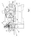
figure 1 is a front view of a grinding machine according to the invention, -
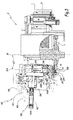
figure 2 is a partially cut top view of the machine offigure 1 in a first working configuration, -
figure 3 is a top view similar tofigure 2 when the machine is in another working configuration, -
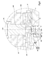
figure 4 is an enlarged view of detail IV onfigure 3 , -
figure 5 is a partial perspective view of the machine offigures 1 to 4 showing some adjustment means, -
figure 6 is a detailed view similar tofigure 4 when the machine is in another working configuration, and -
figure 7 is a partial perspective view showing some further adjustment means. - The grinding machine 2 represented on
figures 1 to 7 includes aframe 4 and a rotatinggrinding wheel 6 which rotates around a first rotation axis X6. Anelectric motor 8 is used to drivewheel 6 in rotation around axis X6. D6 denotes the outer diameter ofgrinding wheel 6. - Grinding
wheel 6 andmotor 8 are supported by anauxiliary frame 9 which is movable with respect toframe 4 in two opposite directions perpendicular to axis X6, as shown by double arrow A9 onfigure 1 . Axis X6 is fixed with respect toauxiliary frame 9. - The outer
peripheral surface 10 ofgrinding wheel 6 is shaped by aknurl 12 when needed and is used to grind the outer surface of aninner ring 500 of a non-further represented bearing.Knurl 12, which is sometimes called "diamant roller", is also supported byauxiliary frame 9. In the example of the figures,outer surface 10 has a central bump, so that it is used to grind the outerradial surface 502 ofring 500 with a concave groove. - Grinding machine 2 is provided with a working station or
zone 14 where eachring 500 is successively held in position with respect to grindingwheel 6 during a grinding operation. -
Working station 14 includes two support shoes 16 and 18, each provided with a fitting 20, respectively 22. Fitting 20 is adapted to lie against the outer radial surface of amagnetic clamp 24, whereas fitting 22 is made of two parts and adapted to lie against the outerperipheral surface 502 ofring 500. Each support shoe 16 and 18 is mounted on a slider 26, respectively 28. Another slide 30 is used to avoid the escape of thering 500. - When it is loaded in
working station 14, as shown onfigures 1 to 4 and6 , eachring 500 is centered around a central axis X24 ofmagnetic clamp 24 parallel or substantially parallel to axis X6. In this configuration, the central bore 504 ofring 500 is empty and, because of the friction betweensurfaces ring 500 is driven in rotation around axis X24 by the rotation movement of grindingwheel 6 around axis X6. Onfigure 4 , arrow R6 represents the rotation ofgrinding wheel 6 and arrow R500 represents the rotation ofring 500. - Two types of equipment are used to feed
working station 14 withrings 500 and to evacuate the rings from this working station, once they have been processed. In this description, a ring which is not yet processed is called a "black ring", whereas a ring which has been processed by grindingwheel 6 is called a "ground ring". - A
multi-axis robot 100, with 6 degrees of freedom, belongs to the transfer means. It is mounted by itsbase 102 on theframe 4 of grinding machine 2 and includes a multi-articulated arm 104 whose free end is equipped with a clamp 106 adapted to grasp or grip different types ofrings 500, via a proper programming ofrobot 100. - A moving
arm 200 also belongs to the transfer means. This movingarm 200 is rotatable around an axis X200 which is fixed with respect toframe 4 and parallel to axis X6. Near its free end 204 opposite to axisX200 moving arm 200 is provided with means for gripping aring 500 to be moved away from workingstation 14. - Grinding machine 2 includes an
inlet chute 300 whereblack rings 500 move by gravity in the direction of arrow A300. For the sake of simplicity, only onering 500 is represented ininlet chute 300 onfigure 2 .Inlet chute 300 is close torobot 100 which can pick-up aring 500 present ininlet chute 300 when needed. - On the other hand, grinding machine 2 also includes an outlet chute 310 where ground rings 500 are dumped, one after the other. In outlet chute 310, ground rings 500 move by gravity, in the direction of arrow A310. On its side oriented towards
arm 200, outlet chute 310 is equipped with a releaser 312 provided with a notch 314 of a size sufficient to accommodate the gripping means of movingarm 200 but with a transverse dimension, measured between two lateral edges of this notch, smaller than the outer diameter of therings 500. -
Magnetic clamp 24 includes a solenoid activated clutch 242 and achuck 244 made of a magnetic material, such as iron, which has a frontannular surface 244A adapted to come into contact with a backaxial surface 506A of abearing ring 500 present in workingstation 14. Backaxial surface 506A is opposite to a frontaxial surface 506B of this ring which is visible from outside machine 2 in the direction offigure 1 . -
Magnetic clamp 24 is mounted on asupport plate 304 which is movable with respect toframe 4, as explained here-after. - Let us consider that a new type of
bearing ring 500 is to be processed on machine 2. In such a case,knurl 12 is used to shape the outerperipheral edge 10 of grindingwheel 6. Depending on the actual shape to be used forperipheral edge 10,knurl 12 is changed and a new knurl is mounted onto machine 2 with a relatively high level precision. However, because of the dismounting and mounting operations, the exact location of knurl 12 on machine 2 is determined at about +/- 20 µm. This tolerance in the location ofknurl 12 induces that the actual shape ofperipheral surface 10 might not be perfectly centered on axis X6. More precisely, in case the shape of outerperipheral surface 10 includes acentral bump 110 and twoflat surfaces bump 110, these two surfaces might not be perfectly cylindrical but slightly frustoconical. - On the other hand, the outer
peripheral surface 502 of aring 500 includes acentral groove 502A and two normallycylindrical surfaces groove 502A, respectively between this groove and backaxial surface 506A and between this groove and frontaxial surface 506B. It is essential thatsurfaces ring 500, this axis being, in practice, superimposed with axis X24 when such a ring is present in workingstation 14. - If
flat surfaces figure 2 . This is whysupport plate 304 can move with respect toframe 6 between the two positions respectively represented onfigures 2 and3 where an offset angle α between axis X6 and X24 takes a maximum value α1 and a minimum value α2. In the configuration offigure 2 , axes X6 and X24 converge towards the front of machine 2, that is towards the bottom offigure 2 , whereas, in the configuration offigure 3 , these axes converge towards the back of machine 2, that is towards the top offigure 3 . In practice, the absolute values of α1 and α2 is lower than 2 to 3°, so that axes X6 and X24 are globally parallel, that is parallel with a slight non parallelism. - In order to allow this adjustment,
support plate 304 is pivotably mounted with respect toframe 6 around a vertical axis Z304 which is perpendicular to axes X6 and X24. Axis Z304 is said to be vertical insofar as it is vertical when machine 2 lies on a horizontal and flat ground surface. In such a configuration, axes X6 and X24 are horizontal. - P304 denotes a point of the upper surface of
support plate 304 where axis Z304 crosses this surface. Point P304 is a center of rotation ofsupport plate 304 with respect toframe 6. Twoarcuate slots support plate 304 and twoscrews frame 4, throughslots washers screws slots support plate 304 around axis Z304 and point P304, which is represented by double arrow R304 on the figures. - An
electric actuator 410 is used to movesupport plate 304 in rotation around axis Z304 with respect toframe 4. This electric actuator includes anelectric motor 412 which is fixed on abracket 414 rigidly mounted onsupport plate 304. On the other hand, ablock 416 is rigidly mounted with respect toframe 4. The output shaft ofmotor 412 is perpendicular to axis Z304 and drives ascrew 418 which is engaged in a non represented threaded hole ofblock 416. Thus, by actuation ofelectric motor 412, it is possible to bringbracket 414 closer to block 416 or to spread these two parts apart from each other. This relative movement betweenparts motor 412. The accuracy of this displacement can be improved by using a reducer betweenmotor 12 andscrew 418. - d1 denotes a radial distance with respect to axis Z304 between point P304 and
screw 418. On the other hand, d2 denotes a radial distance with respect to axis Z304 measured between point P304 and the center of thefront surface 244A ofannular part 244. The ratio d1/d2 is larger than 5, preferably larger than 10. Thus, a precise control of the orientation ofsurface 244A, that is of axis X24, with respect to axis Z304 can be obtained viaelectric actuator 410. -
Electric actuator 410 also includes anabsolute position sensor 422 which delivers to a non represented control unit an electric signal S422 representative of the relative positions ofitems - On the other hand, the position of
ring 500 along axis X24 has an influence on the accuracy of the grinding process ofgroove 502A, as shown by the comparison offigures 4 and6 . In the configuration offigure 4 , bump 110 is correctly positioned with respect to groove 502A. In the configuration offigure 6 , bump 110 will partially destroysurface 502C and groove 502A will not be completely ground. It is thus essential to correctly position aring 500 along axis X24. - To this end, machine 2 also includes another
electric actuator 430 which is mounted onsupport plate 304 and includes anelectric motor 432 whoseoutput shaft 434 forms a worm screw mechanism with atooth wheel 436. Y434 denotes the longitudinal axis ofoutput shaft 434 which is perpendicular to axes X24 and Z304. -
Tooth wheel 436 drives amovement converter 438 which converts the rotation movement oftooth wheel 436, which is centered on axis X24, into an axial movement ofclutch 242 and chuck 244 along axis X24. - Preferably,
movement converter 438 includes a ball screw mechanism. However, other types of movement conversion mechanisms can be considered. - Thanks to
electric actuator 430, it is possible to precisely control the axial position ofannular part 244 along axis X24. This allows correcting the unsatisfactory situation represented onfigure 6 . - When a new type of
bearing ring 500 is to be processed on machine 2, the reference of the knurl used to shape the outerperipheral surface 10 is known and, provided that machine 2 has been previously calibrated, it is possible to access a memory which stores different values of angle α, as a function of the profile used for outerperipheral surface 10 and/or of the dimensions of therings 500. Thus, an operator who knows the next type of ring to be processed on machine 2, thus the type of profile needed forperipheral surface 10, can select in this memory the right value for angle α and pilotelectric actuator 410 in order to pivot accordingly supportplate 304 around axis Z304. - Once this has been done, it is possible to make a try on a ring in order to determine if the
central bump 110 of the profile is correctly aligned with respect to thegroove 502A along axis X500. After this try has been made, it is possible to measure the axial distance, along axis X500 between the center of thegroove 502A and surfaces 506A and 506B. If the operator detects a default in the centering of thegroove 502A along axis X500, it is possible to measure the offset and to pilotelectric actuator 430 so as to precisely correct this offset. - Since
items chuck 244 along axis X24 can be precisely controlled viamotor 432. -
Electric actuator 430 can also be used to fulfil another function: Indeed, it happens thatfront surface 244A ofchuck 244 is not fully perpendicular to axis X24, because of excessive manipulations ofchuck 244. Thus, oncechuck 244 has been mounted onmagnetic clutch 242, it is possible to useelectric actuator 430 to movemagnetic clamp 24 backwards, that is in the direction of arrow A24 on figure 8. - Then,
auxiliary frame 9 is moved towards axis X24, in the direction of arrow A91, that is in a direction which is globally perpendicular to axes X6 and X24 and parallel to axis Y434. The movement ofauxiliary frame 9 in the direction of arrow A91 brings axes X6 and X24 closer together. At the same time, grindingwheel 6 is driven in rotation around axis X6. This displacement ofauxiliary frame 9 goes on up to when alateral surface 62 of grindingwheel 6 crosses axis X24. In this configuration,surface 62 is aligned withchuck 244 in the direction of axis X24. Then, the displacement ofauxiliary frame 9 is stopped andelectric actuator 430 is piloted in order to movemagnetic clamp 24 in the direction of an arrow A'24, opposite to arrow A24, that is to the front of machine 2. This movement goes on up to whensurface 244A contacts surface 62. - This is detected by the fact that, due to this contact, a
support shaft 246 ofclutch 242 and clutch 244 starts to rotate. This can be detected by a rotation sensor integrated withinconverter 438 or located next totooth wheel 436. - When this contact has been detected, the translation movement of
magnetic clamp 24 along axis X24 is stopped. - Thereafter, this translation movement is started once again, in the same direction and over a given stroke, which provokes a grinding operation of
surface 244A bysurface 62. Then, rotation of thegrinding wheel 6 is stopped. This stroke can be of between 0.01 and 10 mm, preferably equal to 0.1 mm - Thanks to this aspect of the invention, the front surface of
chuck 244 can be precisely machined by grindingwheel 6, once it has already been mounted onclutch 242, so that it defines a planar surface which is correctly oriented with respect to axis X24, provided that angle α has been set to the right value. - Alternatively, grinding wheel rotation around axis X6 can be started once lateral surface has reached its position where it crosses axis X24.
Claims (11)
- Grinding machine (2) for bearing rings (500), this machine including:- a frame (4),- a rotating grinding wheel (6) movable in rotation around a first rotation axis (X6),- a working station (14) where a bearing ring stands during a grinding operation of one of its surfaces (502)- holding means (24) for holding a bearing ring in the working station, these holding means being rotatable around a second rotation axis (X24) and supported by a support plate (304) movable (R304) with respect to the frame, characterized in that the machine includes- a first electric actuator (410) for moving the support plate (304) in rotation with respect to the frame (4), around a third axis (Z304) perpendicular to the first and second rotation axes (X6, X24)- a second electric actuator (430) for moving the holding means (24) in translation along the second rotation axis (X24).
- A grinding machine according claim 1, characterized in that the first electric actuator (410) includes a first electric motor (412) rigidly connected to the support plate (304), in that an output shaft of the first electric motor drives a screw member (418) engaged in a threaded hole of a reference part (416) rigidly connected to the frame (4) and in that the output shaft of the first electric motor is perpendicular to the third axis (Z304).
- A grinding machine according to claim 2, characterized in that it includes a position sensor (422) located next to the first electric motor (412) and configured to detect the position of this motor with respect to the reference part (416).
- A grinding machine according to one of claims 2 or 3, characterized in that a first distance (d1), measured radially with respect to the third axis (Z304) between this axis and the output shaft of the first engine (412), is at least five times larger, preferably at least ten times larger, than a second distance (d2), measured radially with respect to the third axis between this axis and a chuck (244) which belongs to the holding means (24) and is in contact with a bearing ring (500) in the working station (14).
- A grinding machine according to any preceding claim, characterized in that the second electric actuator (430) includes a second electric motor (432) mounted on the support plate (304) and a movement converter (438), also mounted on the support plate and driven by an output shaft of the second electric motor, the movement converter being configured to convert a rotation movement into a translation movement (A24, A'24).
- A grinding machine according to claim 5, characterized in that the movement converter (438) includes a ball-screw mechanism.
- A grinding machine according to one of claims 5 and 6, characterized in that the output shaft (434) of the second electric motor (432) is perpendicular to the second rotation axis (X24) and connected to the movement converter (438) via a worm screw mechanism (434/436).
- Method for automatically adjusting the position of the bearing rings (500) in the working station (14) of a grinding machine (2) according to any one of the preceding claims with respect to its grinding wheel (6), depending on the profile of an edge (10) of the grinding wheel and/or on the dimensions of the bearing ring, characterized in that, it includes at least the following steps consisting in:a) accessing a memory where angular offset values (α1, α2) are stored, for an angle (α) measured between the first and second rotation axes (X6, X24) for different edge profiles and/or bearing ring dimensions;b) selecting an angular offset value in the memory, as a function of the profile of the edge and/or of the bearing ring dimensions; andc) piloting the first electric actuator (410) in order to obtain the selected angular offset value between the first and second rotation axes.
- A method according to claim 8, characterized in that it includes further steps consisting in:d) grinding a bearing ring (500) with the grinding wheel (6);e) determining the position of a ground zone (502A) of the bearing ring with respect to a front face (506A) and a back face (506B) of the bearing ringf) assessing if the grinding ring has to be moved axially, along the second rotation axis (X24), in order for the ground zone to be centered between the front and back faces and, if yes, to what extent; andg) piloting the second electric actuator (430) in order to move the holding means (24) in accordance with the findings of step f).
- A method according to one of claims 8 and 9, characterized in that it includes further steps consisting in:h) moving the holding means (24) along the second rotation axis (X24), in a direction (A24) away from the grinding wheel (6);i) driving the grinding wheel in rotation around the first axis (X6);j) moving the grinding wheel in a direction (A91) perpendicular to the first rotation axis in order to align, along the second rotation axis (X24), a lateral face (62) of the grinding wheel with a chuck (244) which belongs to the holding means (24) and is configured to be normally in contact with a bearing ring (500) in the working station (14);k) piloting the second electric actuator (430) to move (A'24) the chuck towards the lateral face of the grinding wheel, in translation along the second rotation axis I) detecting a contact between an axial face (244A) of the chuck and the lateral face of the grinding wheelm) piloting the first electric actuator to stop the translation movement of step k) as soon as a contact is detected in step I)n) piloting the first electric actuator to move the chuck (244) still towards the lateral face (62) of the grinding wheel (6) on a given stroke, which provokes a grinding operation of the axial face (244A) of the chuck.
- A method according to claim 10, characterized in that in step I) a contact between the axial face (244A) of the chuck and the lateral face (62) of the grinding wheel (6) is detected via the rotation of a shaft (246) integral in rotation with the chuck.
Priority Applications (4)
| Application Number | Priority Date | Filing Date | Title |
|---|---|---|---|
| EP14305619.0A EP2937176A1 (en) | 2014-04-25 | 2014-04-25 | Grinding machine for bearing rings and method for adjusting such a machine |
| US14/693,012 US20150306724A1 (en) | 2014-04-25 | 2015-04-22 | Grinding machine for bearing rings and method for adjusting such a machine |
| JP2015089064A JP2015208851A (en) | 2014-04-25 | 2015-04-24 | Polishing machine for bearing rings and method for adjusting the polishing machine |
| CN201510200973.4A CN105033788A (en) | 2014-04-25 | 2015-04-24 | Grinding machine for bearing rings and method for adjusting such a machine |
Applications Claiming Priority (1)
| Application Number | Priority Date | Filing Date | Title |
|---|---|---|---|
| EP14305619.0A EP2937176A1 (en) | 2014-04-25 | 2014-04-25 | Grinding machine for bearing rings and method for adjusting such a machine |
Publications (1)
| Publication Number | Publication Date |
|---|---|
| EP2937176A1 true EP2937176A1 (en) | 2015-10-28 |
Family
ID=50630735
Family Applications (1)
| Application Number | Title | Priority Date | Filing Date |
|---|---|---|---|
| EP14305619.0A Withdrawn EP2937176A1 (en) | 2014-04-25 | 2014-04-25 | Grinding machine for bearing rings and method for adjusting such a machine |
Country Status (4)
| Country | Link |
|---|---|
| US (1) | US20150306724A1 (en) |
| EP (1) | EP2937176A1 (en) |
| JP (1) | JP2015208851A (en) |
| CN (1) | CN105033788A (en) |
Cited By (2)
| Publication number | Priority date | Publication date | Assignee | Title |
|---|---|---|---|---|
| CN109176275A (en) * | 2018-11-08 | 2019-01-11 | 山东宏旺实业有限公司 | A kind of back lining bearing grinding device |
| CN115609419A (en) * | 2022-11-13 | 2023-01-17 | 上海天虹微型轴承有限公司 | Multi-station grinding equipment for shaft coupling, coupling bearing rings and non-magnetic rings |
Families Citing this family (3)
| Publication number | Priority date | Publication date | Assignee | Title |
|---|---|---|---|---|
| CN113370006A (en) * | 2021-05-26 | 2021-09-10 | 浙江赛赛轴承有限公司 | Bearing ring polishing equipment capable of machining multiple surfaces |
| CN116141122B (en) * | 2022-10-20 | 2024-08-02 | 山东彩山铝业有限公司 | Archaize aluminum profile prefabricated part welding polishing device |
| CN120190693B (en) * | 2025-05-26 | 2025-08-22 | 宁波达克轴承有限公司 | A bearing cylindrical grinding machine |
Citations (3)
| Publication number | Priority date | Publication date | Assignee | Title |
|---|---|---|---|---|
| DE2814374A1 (en) * | 1977-04-13 | 1978-10-19 | Famir Int Spa | Grinding machine for annular workpieces outside dia. - has workpiece carrier rotating in steps for transport between work stations |
| US5148638A (en) * | 1991-02-16 | 1992-09-22 | Ernst Thielenhaus Kg | Apparatus for grinding an annular workpiece |
| WO2008082140A1 (en) | 2006-12-29 | 2008-07-10 | Samsung Electronics Co., Ltd. | Method and apparatus for transmitting reverse ack/nack for forward control channel in mobile communication system supporting harq |
Family Cites Families (1)
| Publication number | Priority date | Publication date | Assignee | Title |
|---|---|---|---|---|
| US2807916A (en) * | 1954-04-12 | 1957-10-01 | Federal Mogul Bower Bearings | Simultaneous external and internal centerless grinding machine |
-
2014
- 2014-04-25 EP EP14305619.0A patent/EP2937176A1/en not_active Withdrawn
-
2015
- 2015-04-22 US US14/693,012 patent/US20150306724A1/en not_active Abandoned
- 2015-04-24 CN CN201510200973.4A patent/CN105033788A/en active Pending
- 2015-04-24 JP JP2015089064A patent/JP2015208851A/en active Pending
Patent Citations (3)
| Publication number | Priority date | Publication date | Assignee | Title |
|---|---|---|---|---|
| DE2814374A1 (en) * | 1977-04-13 | 1978-10-19 | Famir Int Spa | Grinding machine for annular workpieces outside dia. - has workpiece carrier rotating in steps for transport between work stations |
| US5148638A (en) * | 1991-02-16 | 1992-09-22 | Ernst Thielenhaus Kg | Apparatus for grinding an annular workpiece |
| WO2008082140A1 (en) | 2006-12-29 | 2008-07-10 | Samsung Electronics Co., Ltd. | Method and apparatus for transmitting reverse ack/nack for forward control channel in mobile communication system supporting harq |
Cited By (3)
| Publication number | Priority date | Publication date | Assignee | Title |
|---|---|---|---|---|
| CN109176275A (en) * | 2018-11-08 | 2019-01-11 | 山东宏旺实业有限公司 | A kind of back lining bearing grinding device |
| CN109176275B (en) * | 2018-11-08 | 2023-10-03 | 山东宏旺实业有限公司 | Backing bearing grinding device |
| CN115609419A (en) * | 2022-11-13 | 2023-01-17 | 上海天虹微型轴承有限公司 | Multi-station grinding equipment for shaft coupling, coupling bearing rings and non-magnetic rings |
Also Published As
| Publication number | Publication date |
|---|---|
| JP2015208851A (en) | 2015-11-24 |
| US20150306724A1 (en) | 2015-10-29 |
| CN105033788A (en) | 2015-11-11 |
Similar Documents
| Publication | Publication Date | Title |
|---|---|---|
| US20150306724A1 (en) | Grinding machine for bearing rings and method for adjusting such a machine | |
| EP2937175A1 (en) | Grinding machine for bearing rings and method for setting tangency conditions in such a machine | |
| CN105729306B (en) | The abrasive machining method and apparatus supported for robot | |
| US8900034B2 (en) | Machine tool and machining method | |
| EP2554315A1 (en) | Gear processing machine | |
| EP2937172A1 (en) | Workpieces processing machine and method for automatically controlling the dimensions of workpieces in such a machine | |
| KR20080060166A (en) | Indexing device | |
| KR20190008881A (en) | Inspection device for rocking forging device, tool for inspection, inspection method, manufacturing device of bearing unit, and manufacturing method of bearing unit | |
| US20150306723A1 (en) | Grinding machine for bearing rings and method for moving a bearing ring in such a machine | |
| JP5770381B2 (en) | Honing method with centering of workpiece in inspection station | |
| KR101660956B1 (en) | rotating table for workpiece processing | |
| US11828671B2 (en) | Method for determining the mass and the position of the centre of gravity of an additional load of a movement system, in particular in the case of a machine tool | |
| CN105234804B (en) | Grinding and polishing device | |
| JPS641242B2 (en) | ||
| WO2012046614A1 (en) | Dressing device | |
| JP5388133B2 (en) | Spring grinding apparatus and spring grinding method | |
| US4312155A (en) | Apparatus for grinding grooves in the inner race of a constant velocity universal joint | |
| CN112476060A (en) | Special machine tool cutter length detection device | |
| JP4072929B2 (en) | Lapping machine and lapping method | |
| JPS59192455A (en) | Neumerical controlled tool grinding machine | |
| JP2017080831A (en) | Processing equipment | |
| CN112935903B (en) | Clamp device of numerical control equipment | |
| JP6913654B2 (en) | Machining method and processing equipment for steel pipe end | |
| CN121004497A (en) | A fine polishing equipment for the inner wall of a circular hole in a metal workpiece | |
| JPH05228834A (en) | Grindstone dressing equipment |
Legal Events
| Date | Code | Title | Description |
|---|---|---|---|
| PUAI | Public reference made under article 153(3) epc to a published international application that has entered the european phase |
Free format text: ORIGINAL CODE: 0009012 |
|
| AK | Designated contracting states |
Kind code of ref document: A1 Designated state(s): AL AT BE BG CH CY CZ DE DK EE ES FI FR GB GR HR HU IE IS IT LI LT LU LV MC MK MT NL NO PL PT RO RS SE SI SK SM TR |
|
| AX | Request for extension of the european patent |
Extension state: BA ME |
|
| STAA | Information on the status of an ep patent application or granted ep patent |
Free format text: STATUS: THE APPLICATION IS DEEMED TO BE WITHDRAWN |
|
| 18D | Application deemed to be withdrawn |
Effective date: 20160429 |