EP2937154A1 - Mandrel of coil box - Google Patents
Mandrel of coil box Download PDFInfo
- Publication number
- EP2937154A1 EP2937154A1 EP13868911.2A EP13868911A EP2937154A1 EP 2937154 A1 EP2937154 A1 EP 2937154A1 EP 13868911 A EP13868911 A EP 13868911A EP 2937154 A1 EP2937154 A1 EP 2937154A1
- Authority
- EP
- European Patent Office
- Prior art keywords
- mandrel
- bar
- slot
- end portion
- leading end
- Prior art date
- Legal status (The legal status is an assumption and is not a legal conclusion. Google has not performed a legal analysis and makes no representation as to the accuracy of the status listed.)
- Withdrawn
Links
Images




Classifications
-
- B—PERFORMING OPERATIONS; TRANSPORTING
- B21—MECHANICAL METAL-WORKING WITHOUT ESSENTIALLY REMOVING MATERIAL; PUNCHING METAL
- B21C—MANUFACTURE OF METAL SHEETS, WIRE, RODS, TUBES, PROFILES OR LIKE SEMI-MANUFACTURED PRODUCTS OTHERWISE THAN BY ROLLING; AUXILIARY OPERATIONS USED IN CONNECTION WITH METAL-WORKING WITHOUT ESSENTIALLY REMOVING MATERIAL
- B21C47/00—Winding-up, coiling or winding-off metal wire, metal band or other flexible metal material characterised by features relevant to metal processing only
- B21C47/28—Drums or other coil-holders
-
- B—PERFORMING OPERATIONS; TRANSPORTING
- B21—MECHANICAL METAL-WORKING WITHOUT ESSENTIALLY REMOVING MATERIAL; PUNCHING METAL
- B21C—MANUFACTURE OF METAL SHEETS, WIRE, RODS, TUBES, PROFILES OR LIKE SEMI-MANUFACTURED PRODUCTS OTHERWISE THAN BY ROLLING; AUXILIARY OPERATIONS USED IN CONNECTION WITH METAL-WORKING WITHOUT ESSENTIALLY REMOVING MATERIAL
- B21C47/00—Winding-up, coiling or winding-off metal wire, metal band or other flexible metal material characterised by features relevant to metal processing only
- B21C47/02—Winding-up or coiling
- B21C47/04—Winding-up or coiling on or in reels or drums, without using a moving guide
-
- B—PERFORMING OPERATIONS; TRANSPORTING
- B21—MECHANICAL METAL-WORKING WITHOUT ESSENTIALLY REMOVING MATERIAL; PUNCHING METAL
- B21C—MANUFACTURE OF METAL SHEETS, WIRE, RODS, TUBES, PROFILES OR LIKE SEMI-MANUFACTURED PRODUCTS OTHERWISE THAN BY ROLLING; AUXILIARY OPERATIONS USED IN CONNECTION WITH METAL-WORKING WITHOUT ESSENTIALLY REMOVING MATERIAL
- B21C47/00—Winding-up, coiling or winding-off metal wire, metal band or other flexible metal material characterised by features relevant to metal processing only
- B21C47/16—Unwinding or uncoiling
- B21C47/18—Unwinding or uncoiling from reels or drums
-
- B—PERFORMING OPERATIONS; TRANSPORTING
- B21—MECHANICAL METAL-WORKING WITHOUT ESSENTIALLY REMOVING MATERIAL; PUNCHING METAL
- B21C—MANUFACTURE OF METAL SHEETS, WIRE, RODS, TUBES, PROFILES OR LIKE SEMI-MANUFACTURED PRODUCTS OTHERWISE THAN BY ROLLING; AUXILIARY OPERATIONS USED IN CONNECTION WITH METAL-WORKING WITHOUT ESSENTIALLY REMOVING MATERIAL
- B21C47/00—Winding-up, coiling or winding-off metal wire, metal band or other flexible metal material characterised by features relevant to metal processing only
- B21C47/24—Transferring coils to or from winding apparatus or to or from operative position therein; Preventing uncoiling during transfer
-
- B—PERFORMING OPERATIONS; TRANSPORTING
- B21—MECHANICAL METAL-WORKING WITHOUT ESSENTIALLY REMOVING MATERIAL; PUNCHING METAL
- B21C—MANUFACTURE OF METAL SHEETS, WIRE, RODS, TUBES, PROFILES OR LIKE SEMI-MANUFACTURED PRODUCTS OTHERWISE THAN BY ROLLING; AUXILIARY OPERATIONS USED IN CONNECTION WITH METAL-WORKING WITHOUT ESSENTIALLY REMOVING MATERIAL
- B21C47/00—Winding-up, coiling or winding-off metal wire, metal band or other flexible metal material characterised by features relevant to metal processing only
- B21C47/32—Tongs or gripping means specially adapted for reeling operations
- B21C47/323—Slits or pinces on the cylindrical wall of a reel or bobbin, adapted to grip the end of the material being wound
-
- B—PERFORMING OPERATIONS; TRANSPORTING
- B21—MECHANICAL METAL-WORKING WITHOUT ESSENTIALLY REMOVING MATERIAL; PUNCHING METAL
- B21C—MANUFACTURE OF METAL SHEETS, WIRE, RODS, TUBES, PROFILES OR LIKE SEMI-MANUFACTURED PRODUCTS OTHERWISE THAN BY ROLLING; AUXILIARY OPERATIONS USED IN CONNECTION WITH METAL-WORKING WITHOUT ESSENTIALLY REMOVING MATERIAL
- B21C49/00—Devices for temporarily accumulating material
Definitions
- the present disclosure relates to a mandrel of a coil box, and more particularly, to a mandrel of a coil box for preventing cooling and plastic deformation of a leading end portion of a bar inserted through a slot in the mandrel and reducing the insertion length of the leading end portion.
- FIG. 1 is a view illustrating a rolling apparatus including a coil box 100 in the related art.
- a continuous casting process is performed using a ladle 5 filled with molten steel refined in a steel making process, a tundish 10 configured to receive the molten steel from the ladle 5 through an injection nozzle connected to the ladle 5 and temporarily store the molten steel, a mold 15 configured to receive the molten steel and initially solidify the molten steel in a predetermined shape, and a plurality of segments 20 disposed below the mold 15 to perform a series of operations for bending or stretching a non-solidified slab while cooling the slab.
- a slab is cooled and reduced while passing through the segments 20.
- the slab may be subjected to rough rolling, shearing, and heating by a roughing mill 25, shears 30 and 35, and an inductive heater 40.
- the slab may be formed as a bar 1 through such processes and fed to the coil box 100 so as to be coiled or uncoiled.
- a bar 1 being continuously fed, may be processed as plate scrap by the shears 30 and 35.
- a shear 45, a finishing mill 50, a run-out table 55, a final shear 60, and a coiler 70 may be sequentially arranged after the coil box 100 so that the bar 1 discharged from the coil box 100 may be continuously rolled, sheared, and coiled as a coil.
- the above-explained processes are examples to which a coil box of the present disclosure may be applied.
- the coil box of the present disclosure may be used in various steel processing processes.
- the coil box 100 functions as a buffer to allow a continuous process.
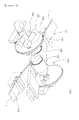
- the coil box 100 will now be described in more detail with reference to FIGS. 2 to 5 .
- FIG. 2 is a perspective view illustrating the coil box 100 in the rolling apparatus illustrated in FIG. 1
- FIG. 3 is another perspective view illustrating the coil box 100 of FIG. 2
- FIG. 4 is a plan view illustrating the coil box 100 of FIG. 2
- FIG. 5 is a cross-sectional view taken along line I-I' of FIG. 4 .
- the coil box 100 may coil a roughly-rolled bar 1 and maintain the bar 1 at a constant temperature to reduce temperature and texture differences between the leading and trailing ends of the bar 1.
- An introduction unit 112 is installed in front of the coil box 100, and a bar 1 is introduced to the coil box 100 through the introduction unit 112.
- a leveler 116 is installed behind the coil box 100, and the bar 1 is discharged through the leveler 116.
- a carousel 130 may be disposed in the coil box 100 for coiling or uncoiling a bar 1.
- the carousel 130 may swing mandrels 132 to shift the positions of the mandrels 132.
- the carousel 130 may be connected to a driving unit 140.
- the carousel 130 may include the mandrels 132 and rotating wheels 134.
- the mandrels 132 are provided as a pair. One of the mandrels 132 (first mandrel 132) is used to coil a bar 1 introduced to the coil box 100, and the other of the mandrels 132 (second mandrel 132') is used to uncoil and discharge another bar 1, previously coiled.
- the carousel 130 may rotate the rotating wheels 134 using the driving unit 140 to shift the positions of the first and second mandrels 132 and 132'. Then, the first mandrel 132 around which the bar 1 is coiled uncoils the bar 1, and the second mandrel 132' around which no bar 1 is coiled coils a newly-introduced bar 1.
- the carousel 130 shifts the positions of the first and second mandrels 132 and 132' to shift coiling and uncoiling and thus to allow for continuous processing.
- Motors 136 may be connected to the first and second mandrels 132 and 132' to rotate the first and second mandrels 132 and 132', and decelerators 138 may be connected to the first and second mandrels 132 and 132' to control the rotating speeds thereof.
- a passage through which a leading end portion of a bar 1 is inserted into the mandrel 132 (hereinafter, the first and second mandrels 132 and 132' will be collectively referred to as a mandrel 132) for coiling may be precisely tracked and controlled so as to prevent coiling failure and perform a continuous process without interruption.
- An aspect of the present disclosure may provide a mandrel of a coil box, the mandrel including a guide part protruding from an edge wall of a slot of the mandrel into the mandrel to prevent a leading end portion of a bar inserted through the slot from making contact with a center shaft, thereby preventing cooling and plastic deformation of the leading end portion and reducing the insertion length of the leading end portion.
- a mandrel of a coil box includes: a cylindrical mandrel main body in which a center shaft is disposed, the mandrel main body including a slot to receive a leading end portion of a high-temperature bar; and a guide part formed from an edge wall of the slot toward an inner side of the mandrel main body so as to prevent cooling and plastic deformation of the leading end portion of the bar inserted through the slot.
- the guide part may protrude from the edge wall of the slot to prevent the leading end portion of the bar from making contact with the center shaft when the leading end portion of the bar is inserted through the slot.
- An inner end of the guide part may be spaced apart from an inner end of an opposite edge wall of the slot by 90 mm to 110 mm.
- the guide part may be sloped in a manner such that an inner gap of the slot is smaller than an outer gap of the slot.
- An outer end of the guide part may be spaced apart from an outer end of an opposite edge wall of the slot by 200 mm to 300 mm.
- the guide part may be formed in one piece with the mandrel main body and may extend from the edge wall of the slot toward the inner side of the mandrel main body.
- the guide part may protrude from the edge wall of the slot and taper toward the inner side of the mandrel main body.
- a counterweight may be provided on a side of the mandrel main body opposite to the guide part so as not to bias a center of gravity of the mandrel toward the guide part.
- the guide part protruding from the edge wall of the slot of the mandrel into the mandrel prevents a leading end portion of a bar inserted through the slot from making contact with the center shaft, thereby preventing cooling and plastic deformation of the leading end portion and reducing the insertion length of the leading end portion.
- a tail portion (corresponding to a leading end portion of a bar in mandrel coiling) may have a uniform temperature and thus may not be curled or tangled.
- work rolls may not be damaged by a curled or tangled bar, and product quality may not be deteriorated.
- the length of a leading end portion of a bar inserted through the slot into the mandrel may be shortened, and when the bar is coiled around the mandrel, a portion of the bar making contact with the opposite edge wall of the slot may not be easily bent and plastically deformed. That is, deflection of the leading end portion of the bar may be prevented when the bar is coiled, and since the leading end portion is brought into contact with the guide part and supported on the guide part with an appropriate contact force therebetween, initial turns of the bar may be smoothly formed when the bar is coiled around the mandrel. Thus, the coiling process may not be suspended due to initial turn errors.
- FIG. 6 is a view illustrating how the leading end portion 1a of the bar 1 is inserted into the slot 132a of the mandrel 132 and is coiled in the related art.
- the bar 1, heated to a high temperature and having a thickness of 16 mm to 23 mm, is coiled in the mandrel 132 as follows.
- the leading end portion 1a of the bar 1 is inserted into the mandrel 132 through the slot 132a (having a gap of 310 mm) by a length of about 800 mm to 1,000 mm.
- the leading end portion 1a of the bar 1 is brought into contact with a center shaft 133 of the mandrel 132, and as the mandrel 132 rotates, the leading end portion 1a is brought into contact with an opposite edge wall 132c of the slot 132a.
- the leading end portion 1a is bent at a position making contact with the opposite edge wall 132c and brought into contact with the outer surface of the mandrel 132. In this manner, an initial inner turn of the bar 1 is formed and the bar 1 is coiled.
- the center shaft 133 is coated with an insulator having a triple structure, the leading end portion 1a (about 800 mm to 1,000 mm) of the bar 1, inserted in the mandrel 132 and making contact with the center shaft 133, is inevitably cooled because temperature around the center shaft 133 is about 650°C due to the influence of coolant flowing in the center shaft 133.
- a cooled portion of the bar 1 may be rolled at a temperature lower than an Ar3 transformation point to cause structural failures and texture errors, and during thin-plate rolling, a tail portion may have a non-uniform temperature and thus may be curled or tangled. Such failures or defects may damage work rolls to result in product quality deterioration and even workplace accidents such as roll breakage.
- the above-mentioned tail portion may correspond to the leading end portion 1a of the coiled bar 1. That is, during uncoiling, the leading end portion 1a becomes a tail portion.
- finishing rolling process it may be important to maintain the entire length and width of a hot-rolled coil at a uniform finishing mill delivery temperature (FDT) equal to or higher than an Ar3 transformation point (870°C).
- FDT uniform finishing mill delivery temperature
- the tail of the bar 1 (a leading end portion in a mandrel coiling process) enters the FM in a state in which the tail has a temperature lower than that of the other normal part of the bar 1 by about 100°C because the structure of the mandrel 132 used to coil the bar 1.
- the tail When the tail exits the FM, the tail has a temperature of 800°C or lower. Therefore, the bar 1 processed by the FM may not satisfy properties required of steel sheets.
- Table 1 Standards Sampling positions (skin-pass top portion) Elongation range FDT (minimum) HS5282601 JS-SPHC 0m 5m 10m 15m 20m Lower limit Upper limit 822°C Analysis results (3,It) TS 408 418 393 401 391 270 - YP 322 321 290 291 279 - EL 24 25 30 34 34 27 - [Sampling positions and texture test results] * FDT: Finishing Mill Delivery Temperature (temperature of bar 1 after finishing rolling).
- a relatively low-temperature portion of a coil corresponding to the tail of a bar 1 in a skin pass rolling process was sampled at intervals of 5 m, and mechanical properties of the samples were measured in a length direction thereof. Samples collected within 5 m from the end of the tail did not satisfy the lower limit of a target range of elongation. The results of texture defects are shown in Table 1.
- a leading end portion 1a (about 800 mm to 1,000 mm) of a bar 1 inserted in the mandrel 132 is cut off because the leading end portion 1a causes texture defects.
- the sampling length is calculated based on the thickness of the coil so as to fully detect and remove defective portions.
- an intermediate inspector or an operator of a skin pass mill may be overburdened, and a skin pass rolling process may be additionally performed.
- the yield of the skin pass rolling process may be lowered because defective portions are cut off.
- a bar 1 is coiled using the mandrel 132 as follows.
- a leading end portion 1a of the bar 1 is inserted into the mandrel 132 through the slot 132a of the mandrel 132, and then the leading end portion 1a is supported on the center shaft 133 and the opposite edge wall 312. Therefore, as the mandrel 132 is rotated, the leading end portion 1a is bent, and an initial turn of a coil is formed.
- initial turns of a coil may be defectively formed due to deflection, and a coiling process may be frequently suspended. Therefore, a mandrel having an improved structure may be required.
- a mandrel 300 of a coil box improved according to the present disclosure will now be described in comparison with the mandrel 132 of the related art shown in FIG. 6 .
- FIG. 7 is a view illustrating how a leading end portion 1a of a bar 1 is inserted into a slot 310c of the mandrel 300 and is coiled according to an exemplary embodiment of the present disclosure.
- the mandrel 300 includes a mandrel main body 310 in which the slot 310c is formed, and a guide part 320 formed on an edge wall 311 of the slot 310c of the mandrel main body 310.
- a center shaft 200 is disposed in the mandrel main body 310, and the slot 310c is formed in the mandrel main body 310 to receive the leading end portion 1a of the bar 1. Coolant flows in the mandrel 300, and thus the temperature of the mandrel 300 is lower than the bar 1 having a high temperature.
- the guide part 320 is formed from the edge wall 311 of the slot 310c toward an inner side of the mandrel main body 310 so as to prevent cooling and plastic deformation of the leading end portion 1a of the bar 1 inserted through the slot 310c.
- the guide part 320 may protrude from the edge wall 311 of the slot 310c so as to prevent the leading end portion 1a of the bar 1 from making contact with the center shaft 200 when the leading end portion 1a of the bar 1 is inserted through the slot 310c.
- a tail portion (corresponding to a leading end portion of a bar in mandrel coiling) may have a uniform temperature and thus may not be curled or tangled. Thus, work rolls may not be damaged, and product quality may not be deteriorated.
- the leading end portion 1a of the bar 1 is inserted through the slot 310c by a length of about 400 mm to about 500 mm shorter than an insertion length of about 800 mm to about 1,000 mm in the related art, and thus when the bar 1 is coiled around the mandrel 300, a portion of the bar 1 making contact with the opposite edge wall 312 of the slot 310c may not be easily bent and plastically deformed.
- the leading end portion 1a of the bar 1 inserted into the slot 310c may not undergo deflection but may make contact with the guide part 320 with an appropriate contact force therebetween. Therefore, initial inner turns of the bar 1 may be smoothly formed around the mandrel 300, and thus the coiling process may not be suspended due to defective initial inner turns.
- the inner end of the guide part 320 is spaced apart from the inner end of the opposite edge wall 312 of the slot 310c by a distance of 90 mm to 110 mm. Since the guide part 320 protrudes until the guide part 320 is spaced apart from the inner end of the opposite edge wall 312 by the distance, when the leading end portion 1a of the bar 1 is inserted in the slot 310c, the leading end portion 1a does not make contact with the center shaft 200. In addition, when the bar 1 is coiled around the mandrel 300, a portion of the bar 1 making contact with the opposite edge wall 312 may not be easily bent and plastically deformed.
- the guide part 320 may be sloped in a manner such that an inner gap (inner width) of the slot 310c is smaller than an outer gap (outer width) of the slot 310c.
- the bar 1 since the outer gap of the slot 310c is greater than the inner gap of the slot 310c, the bar 1 may be easily inserted into the slot 310c, and the guide part 320 may stably guide the insertion of the bar 1 into the slot 310c.
- the guide part 320 is disposed in the mandrel main body 310 and narrows the inner gap of the slot 310c, when the leading end portion 1a of the bar 1 is inserted, the leading end portion 1a may be prevented from making contact with the center shaft 200.
- the outer end of the guide part 320 may be spaced apart form the outer end of the opposite edge wall 312 by a distance of 200 mm to 300 mm, and in this case, the guide part 320 may more effectively function as an insertion guide.
- the guide part 320 may be formed in one piece with the mandrel main body 310 and may extend from the edge wall 311 of the slot 310c into the mandrel main body 310.
- the leading end portion 1a of the bar 1 inserted in the mandrel main body 310 may be cooled by the center shaft 200, close to the leading end portion 1a. However, since the guide part 320 formed in one piece with the mandrel main body 310 makes contact with the leading end portion 1a of the bar 1 in the mandrel main body 310, the leading end portion 1a may be maintained at an appropriate temperature in the mandrel main body 310.
- leading end portion 1a of the bar 1 may receive heat from the other high-temperature portion of the bar 1 coiled around the mandrel main body 310 through the mandrel main body 310 and the guide part 320 formed in one piece, and thus the leading end portion 1a may be maintained at a high temperature.
- the guide part 320 may protrude from the edge wall 311 of the slot 310c and taper toward the inside of the mandrel main body 310. In this case, although the guide part 320 may transfer heat through a wide area thereof, the guide part 320 may not make contact with the center shaft 200.
- counterweights 330 may be formed on a side of the mandrel main body 310 opposite to the guide part 320 so as not to bias the center of gravity of the mandrel 300 toward the guide part 320.
- the counterweights 330 protrude from an inner side of the mandrel main body 310.
- the current embodiment is not limited thereto. That is, the number and shape of the counterweights 330 are not limited as long as the counterweights 330 cancel out the weight of the guide part 320.
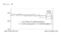
- the mandrel 300 of the embodiment of the present disclosure was applied to a production line, and as shown in a graph below, the finishing mill delivery temperature (FDT) of a leading end portion 1a of a bar 1 that had been inserted in the mandrel 300 and processed through a finishing rolling process was different as compared to an FDT measured in a product line of the related art.
- the x-axis denotes a bar length
- the y-axis denotes bar temperature (°C)
- FDT (before improvement) denotes FDT measured according to the related art
- FDT (after improvement) denotes FDT measured according to the present disclosure.
- a steel sheet or bar may be smoothly and stably rolled in a finishing rolling process.
- intermediate inspectors may be less burdened when inspecting for texture defects caused by a low temperature at the leading end of a bar, and operators may be less burdened when performing a skin pass rolling process for correcting defects. Furthermore, the yield of a skin pass rolling process may not be lowered due to removal of a defective portion.
Landscapes
- Engineering & Computer Science (AREA)
- Mechanical Engineering (AREA)
- Winding, Rewinding, Material Storage Devices (AREA)
- Storage Of Web-Like Or Filamentary Materials (AREA)
- Manufacture Of Motors, Generators (AREA)
Abstract
Description
- The present disclosure relates to a mandrel of a coil box, and more particularly, to a mandrel of a coil box for preventing cooling and plastic deformation of a leading end portion of a bar inserted through a slot in the mandrel and reducing the insertion length of the leading end portion.
-
FIG. 1 is a view illustrating a rolling apparatus including acoil box 100 in the related art. - Referring to
FIG. 1 , a continuous casting process is performed using aladle 5 filled with molten steel refined in a steel making process, a tundish 10 configured to receive the molten steel from theladle 5 through an injection nozzle connected to theladle 5 and temporarily store the molten steel, amold 15 configured to receive the molten steel and initially solidify the molten steel in a predetermined shape, and a plurality ofsegments 20 disposed below themold 15 to perform a series of operations for bending or stretching a non-solidified slab while cooling the slab. - In such a continuous casting process, a slab is cooled and reduced while passing through the
segments 20. After passing through thesegments 20, the slab may be subjected to rough rolling, shearing, and heating by a roughingmill 25,shears inductive heater 40. - The slab may be formed as a
bar 1 through such processes and fed to thecoil box 100 so as to be coiled or uncoiled. - For example, if coiling or uncoiling in the
coil box 100 is delayed, abar 1, being continuously fed, may be processed as plate scrap by theshears - A
shear 45, a finishingmill 50, a run-out table 55, afinal shear 60, and acoiler 70 may be sequentially arranged after thecoil box 100 so that thebar 1 discharged from thecoil box 100 may be continuously rolled, sheared, and coiled as a coil. - The above-explained processes are examples to which a coil box of the present disclosure may be applied. The coil box of the present disclosure may be used in various steel processing processes.
- In a hot direct rolling process, the
coil box 100 functions as a buffer to allow a continuous process. Thecoil box 100 will now be described in more detail with reference toFIGS. 2 to 5 . -
FIG. 2 is a perspective view illustrating thecoil box 100 in the rolling apparatus illustrated inFIG. 1 ,FIG. 3 is another perspective view illustrating thecoil box 100 ofFIG. 2 ,FIG. 4 is a plan view illustrating thecoil box 100 ofFIG. 2 , andFIG. 5 is a cross-sectional view taken along line I-I' ofFIG. 4 . - The
coil box 100 may coil a roughly-rolledbar 1 and maintain thebar 1 at a constant temperature to reduce temperature and texture differences between the leading and trailing ends of thebar 1. - An
introduction unit 112 is installed in front of thecoil box 100, and abar 1 is introduced to thecoil box 100 through theintroduction unit 112. Aleveler 116 is installed behind thecoil box 100, and thebar 1 is discharged through theleveler 116. - A
carousel 130 may be disposed in thecoil box 100 for coiling or uncoiling abar 1. Thecarousel 130 may swingmandrels 132 to shift the positions of themandrels 132. Thecarousel 130 may be connected to adriving unit 140. - The
carousel 130 may include themandrels 132 and rotatingwheels 134. - The
mandrels 132 are provided as a pair. One of the mandrels 132 (first mandrel 132) is used to coil abar 1 introduced to thecoil box 100, and the other of the mandrels 132 (second mandrel 132') is used to uncoil and discharge anotherbar 1, previously coiled. - After the
first mandrel 132 coils abar 1 and thesecond mandrel 132' uncoils abar 1, thecarousel 130 may rotate the rotatingwheels 134 using thedriving unit 140 to shift the positions of the first andsecond mandrels first mandrel 132 around which thebar 1 is coiled uncoils thebar 1, and thesecond mandrel 132' around which nobar 1 is coiled coils a newly-introducedbar 1. - In this manner, the
carousel 130 shifts the positions of the first andsecond mandrels -
Motors 136 may be connected to the first andsecond mandrels second mandrels decelerators 138 may be connected to the first andsecond mandrels - In the above-described
coil box 100, a passage through which a leading end portion of abar 1 is inserted into the mandrel 132 (hereinafter, the first andsecond mandrels - An aspect of the present disclosure may provide a mandrel of a coil box, the mandrel including a guide part protruding from an edge wall of a slot of the mandrel into the mandrel to prevent a leading end portion of a bar inserted through the slot from making contact with a center shaft, thereby preventing cooling and plastic deformation of the leading end portion and reducing the insertion length of the leading end portion.
- According to an aspect of the present disclosure, a mandrel of a coil box includes: a cylindrical mandrel main body in which a center shaft is disposed, the mandrel main body including a slot to receive a leading end portion of a high-temperature bar; and a guide part formed from an edge wall of the slot toward an inner side of the mandrel main body so as to prevent cooling and plastic deformation of the leading end portion of the bar inserted through the slot.
- The guide part may protrude from the edge wall of the slot to prevent the leading end portion of the bar from making contact with the center shaft when the leading end portion of the bar is inserted through the slot.
- An inner end of the guide part may be spaced apart from an inner end of an opposite edge wall of the slot by 90 mm to 110 mm.
- The guide part may be sloped in a manner such that an inner gap of the slot is smaller than an outer gap of the slot.
- An outer end of the guide part may be spaced apart from an outer end of an opposite edge wall of the slot by 200 mm to 300 mm.
- The guide part may be formed in one piece with the mandrel main body and may extend from the edge wall of the slot toward the inner side of the mandrel main body. The guide part may protrude from the edge wall of the slot and taper toward the inner side of the mandrel main body.
- A counterweight may be provided on a side of the mandrel main body opposite to the guide part so as not to bias a center of gravity of the mandrel toward the guide part.
- As set forth above, according to exemplary embodiments of the present disclosure, the guide part protruding from the edge wall of the slot of the mandrel into the mandrel prevents a leading end portion of a bar inserted through the slot from making contact with the center shaft, thereby preventing cooling and plastic deformation of the leading end portion and reducing the insertion length of the leading end portion.
- Therefore, during thin-plate rolling, a tail portion (corresponding to a leading end portion of a bar in mandrel coiling) may have a uniform temperature and thus may not be curled or tangled. Thus, work rolls may not be damaged by a curled or tangled bar, and product quality may not be deteriorated.
- In addition, the length of a leading end portion of a bar inserted through the slot into the mandrel may be shortened, and when the bar is coiled around the mandrel, a portion of the bar making contact with the opposite edge wall of the slot may not be easily bent and plastically deformed. That is, deflection of the leading end portion of the bar may be prevented when the bar is coiled, and since the leading end portion is brought into contact with the guide part and supported on the guide part with an appropriate contact force therebetween, initial turns of the bar may be smoothly formed when the bar is coiled around the mandrel. Thus, the coiling process may not be suspended due to initial turn errors.
-
-
FIG. 1 is a view illustrating a rolling apparatus including a coil box according to the related art; -
FIG. 2 is a perspective view illustrating the coil box of the rolling apparatus illustratedFIG. 1 ; -
FIG. 3 is another perspective view illustrating the coil box ofFIG. 2 ; -
FIG. 4 is a plan view illustrating the coil box ofFIG. 2 ; -
FIG. 5 is a cross-sectional view taken along line I-I' ofFIG. 4 ; -
FIG. 6 is a view illustrating how the leading end portion of a bar is inserted into a slot of a mandrel and is coiled in the related art; and -
FIG. 7 is a view illustrating how the leading end portion of a bar is inserted into a slot of a mandrel of a coil box and is coiled according to an exemplary embodiment of the present disclosure. - First, with reference to
FIG. 6 , an explanation will be given of how a leadingend portion 1a of abar 1 is inserted into aslot 132a of amandrel 132 and is coiled in the related art. -
FIG. 6 is a view illustrating how the leadingend portion 1a of thebar 1 is inserted into theslot 132a of themandrel 132 and is coiled in the related art. - Referring to
FIG. 6 , thebar 1, heated to a high temperature and having a thickness of 16 mm to 23 mm, is coiled in themandrel 132 as follows. The leadingend portion 1a of thebar 1 is inserted into themandrel 132 through theslot 132a (having a gap of 310 mm) by a length of about 800 mm to 1,000 mm. Then, the leadingend portion 1a of thebar 1 is brought into contact with acenter shaft 133 of themandrel 132, and as themandrel 132 rotates, the leadingend portion 1a is brought into contact with anopposite edge wall 132c of theslot 132a. Then, the leadingend portion 1a is bent at a position making contact with theopposite edge wall 132c and brought into contact with the outer surface of themandrel 132. In this manner, an initial inner turn of thebar 1 is formed and thebar 1 is coiled. - The
center shaft 133 is disposed in themandrel 132 to support themandrel 132 placed in a coil box having a high temperature (1,100°C), and coolant flows in thecenter shaft 133. - Although the
center shaft 133 is coated with an insulator having a triple structure, the leadingend portion 1a (about 800 mm to 1,000 mm) of thebar 1, inserted in themandrel 132 and making contact with thecenter shaft 133, is inevitably cooled because temperature around thecenter shaft 133 is about 650°C due to the influence of coolant flowing in thecenter shaft 133. - Furthermore, during finishing rolling, a cooled portion of the
bar 1 may be rolled at a temperature lower than an Ar3 transformation point to cause structural failures and texture errors, and during thin-plate rolling, a tail portion may have a non-uniform temperature and thus may be curled or tangled. Such failures or defects may damage work rolls to result in product quality deterioration and even workplace accidents such as roll breakage. The above-mentioned tail portion may correspond to theleading end portion 1a of the coiledbar 1. That is, during uncoiling, theleading end portion 1a becomes a tail portion. - In a finishing rolling process, it may be important to maintain the entire length and width of a hot-rolled coil at a uniform finishing mill delivery temperature (FDT) equal to or higher than an Ar3 transformation point (870°C).
- However, when a
bar 1 is processed by a finishing mill (FM), the tail of the bar 1 (a leading end portion in a mandrel coiling process) enters the FM in a state in which the tail has a temperature lower than that of the other normal part of thebar 1 by about 100°C because the structure of themandrel 132 used to coil thebar 1. When the tail exits the FM, the tail has a temperature of 800°C or lower. Therefore, thebar 1 processed by the FM may not satisfy properties required of steel sheets. - So as not to deliver such defective products to customers, defective portions of the products are removed before packaging. However, this lowers the process yield.
- Specific examples showing effects of such temperature decreases are listed in Table 1.
[Table 1] Standards Sampling positions (skin-pass top portion) Elongation range FDT (minimum) HS5282601 JS- SPHC 0m 5m 10m 15m 20m Lower limit Upper limit 822°C Analysis results (3,It) TS 408 418 393 401 391 270 - YP 322 321 290 291 279 - EL 24 25 30 34 34 27 - [Sampling positions and texture test results]
* FDT: Finishing Mill Delivery Temperature (temperature ofbar 1 after finishing rolling). - A relatively low-temperature portion of a coil corresponding to the tail of a
bar 1 in a skin pass rolling process (the tail was a leading end portion in a mandrel coiling process) was sampled at intervals of 5 m, and mechanical properties of the samples were measured in a length direction thereof. Samples collected within 5 m from the end of the tail did not satisfy the lower limit of a target range of elongation. The results of texture defects are shown in Table 1. - In addition, the structures of the samples were analyzed, and mixed-grain structures were observed until about 20 m. Therefore, in the related art, a
leading end portion 1a (about 800 mm to 1,000 mm) of abar 1 inserted in themandrel 132 is cut off because theleading end portion 1a causes texture defects. For example, before collecting quality test samples from a coil, the sampling length is calculated based on the thickness of the coil so as to fully detect and remove defective portions. - Therefore, an intermediate inspector or an operator of a skin pass mill may be overburdened, and a skin pass rolling process may be additionally performed. In addition, the yield of the skin pass rolling process may be lowered because defective portions are cut off.
- A
bar 1 is coiled using themandrel 132 as follows. Aleading end portion 1a of thebar 1 is inserted into themandrel 132 through theslot 132a of themandrel 132, and then theleading end portion 1a is supported on thecenter shaft 133 and theopposite edge wall 312. Therefore, as themandrel 132 is rotated, theleading end portion 1a is bent, and an initial turn of a coil is formed. - At this time, the
bar 1 may receive a force (F) and torque expressed as follows: torque = force (F) x length (L) where the length (L) is a distance between a point of action and a rotation center. As the length (L) increases, thebar 1 may be bent by a smaller force. Therefore, thebar 1 may be easily bent and plastically deformed. That is, in themandrel 132, thebar 1 may be plastically bent at a portion between thecenter shaft 133 and theopposite edge wall 312 of theslot 132a, and thus equilibrium of forces may collapse due to plastic deformation of thebar 1. - In the worst case, initial turns of a coil may be defectively formed due to deflection, and a coiling process may be frequently suspended. Therefore, a mandrel having an improved structure may be required.
- A
mandrel 300 of a coil box improved according to the present disclosure will now be described in comparison with themandrel 132 of the related art shown inFIG. 6 . -
FIG. 7 is a view illustrating how aleading end portion 1a of abar 1 is inserted into aslot 310c of themandrel 300 and is coiled according to an exemplary embodiment of the present disclosure. - Referring to
FIG. 7 , themandrel 300 includes a mandrelmain body 310 in which theslot 310c is formed, and aguide part 320 formed on anedge wall 311 of theslot 310c of the mandrelmain body 310. - A
center shaft 200 is disposed in the mandrelmain body 310, and theslot 310c is formed in the mandrelmain body 310 to receive theleading end portion 1a of thebar 1. Coolant flows in themandrel 300, and thus the temperature of themandrel 300 is lower than thebar 1 having a high temperature. - The
guide part 320 is formed from theedge wall 311 of theslot 310c toward an inner side of the mandrelmain body 310 so as to prevent cooling and plastic deformation of theleading end portion 1a of thebar 1 inserted through theslot 310c. - The
guide part 320 may protrude from theedge wall 311 of theslot 310c so as to prevent theleading end portion 1a of thebar 1 from making contact with thecenter shaft 200 when theleading end portion 1a of thebar 1 is inserted through theslot 310c. - Owing this structure, when the
leading end portion 1a of thebar 1 is inserted, theleading end portion 1a is not brought into contact with thecenter shaft 200 having a relatively low temperature and thus is not cooled to a temperature lower than a proper temperature. - Therefore, during thin-plate rolling, a tail portion (corresponding to a leading end portion of a bar in mandrel coiling) may have a uniform temperature and thus may not be curled or tangled. Thus, work rolls may not be damaged, and product quality may not be deteriorated.
- In addition, since the
leading end portion 1a of thebar 1 is inserted through theslot 310c by a length of about 400 mm to about 500 mm shorter than an insertion length of about 800 mm to about 1,000 mm in the related art, and thus when thebar 1 is coiled around themandrel 300, a portion of thebar 1 making contact with theopposite edge wall 312 of theslot 310c may not be easily bent and plastically deformed. - That is, when the
bar 1 is coiled, theleading end portion 1a of thebar 1 inserted into theslot 310c may not undergo deflection but may make contact with theguide part 320 with an appropriate contact force therebetween. Therefore, initial inner turns of thebar 1 may be smoothly formed around themandrel 300, and thus the coiling process may not be suspended due to defective initial inner turns. - For example, the inner end of the
guide part 320 is spaced apart from the inner end of theopposite edge wall 312 of theslot 310c by a distance of 90 mm to 110 mm. Since theguide part 320 protrudes until theguide part 320 is spaced apart from the inner end of theopposite edge wall 312 by the distance, when theleading end portion 1a of thebar 1 is inserted in theslot 310c, theleading end portion 1a does not make contact with thecenter shaft 200. In addition, when thebar 1 is coiled around themandrel 300, a portion of thebar 1 making contact with theopposite edge wall 312 may not be easily bent and plastically deformed. - The
guide part 320 may be sloped in a manner such that an inner gap (inner width) of theslot 310c is smaller than an outer gap (outer width) of theslot 310c. - That is, since the outer gap of the
slot 310c is greater than the inner gap of theslot 310c, thebar 1 may be easily inserted into theslot 310c, and theguide part 320 may stably guide the insertion of thebar 1 into theslot 310c. - In addition, since the
guide part 320 is disposed in the mandrelmain body 310 and narrows the inner gap of theslot 310c, when theleading end portion 1a of thebar 1 is inserted, theleading end portion 1a may be prevented from making contact with thecenter shaft 200. - For example, the outer end of the
guide part 320 may be spaced apart form the outer end of theopposite edge wall 312 by a distance of 200 mm to 300 mm, and in this case, theguide part 320 may more effectively function as an insertion guide. - In addition, the
guide part 320 may be formed in one piece with the mandrelmain body 310 and may extend from theedge wall 311 of theslot 310c into the mandrelmain body 310. - The
leading end portion 1a of thebar 1 inserted in the mandrelmain body 310 may be cooled by thecenter shaft 200, close to theleading end portion 1a. However, since theguide part 320 formed in one piece with the mandrelmain body 310 makes contact with theleading end portion 1a of thebar 1 in the mandrelmain body 310, theleading end portion 1a may be maintained at an appropriate temperature in the mandrelmain body 310. - That is, the
leading end portion 1a of thebar 1 may receive heat from the other high-temperature portion of thebar 1 coiled around the mandrelmain body 310 through the mandrelmain body 310 and theguide part 320 formed in one piece, and thus theleading end portion 1a may be maintained at a high temperature. - For example, the
guide part 320 may protrude from theedge wall 311 of theslot 310c and taper toward the inside of the mandrelmain body 310. In this case, although theguide part 320 may transfer heat through a wide area thereof, theguide part 320 may not make contact with thecenter shaft 200. - In addition,
counterweights 330 may be formed on a side of the mandrelmain body 310 opposite to theguide part 320 so as not to bias the center of gravity of themandrel 300 toward theguide part 320. - In
FIG. 7 , thecounterweights 330 protrude from an inner side of the mandrelmain body 310. However, the current embodiment is not limited thereto. That is, the number and shape of thecounterweights 330 are not limited as long as thecounterweights 330 cancel out the weight of theguide part 320. - The
mandrel 300 of the embodiment of the present disclosure was applied to a production line, and as shown in a graph below, the finishing mill delivery temperature (FDT) of aleading end portion 1a of abar 1 that had been inserted in themandrel 300 and processed through a finishing rolling process was different as compared to an FDT measured in a product line of the related art. In the graph, the x-axis denotes a bar length, the y-axis denotes bar temperature (°C), FDT (before improvement) denotes FDT measured according to the related art, FDT (after improvement) denotes FDT measured according to the present disclosure. - As shown in the graph, the FDT of a leading end portion of a bar measured after improvement was higher than the FDT of the leading end portion of a bar measured before improvement by about 40°C to about 50°C, and the temperature of one or two inner turns of a coil making contact with the outer surface of the mandrel
main body 310 was increased by about 10°C to about 20°C after improvement. Therefore, according to the present disclosure, a steel sheet or bar may be smoothly and stably rolled in a finishing rolling process. - Therefore, intermediate inspectors may be less burdened when inspecting for texture defects caused by a low temperature at the leading end of a bar, and operators may be less burdened when performing a skin pass rolling process for correcting defects. Furthermore, the yield of a skin pass rolling process may not be lowered due to removal of a defective portion.
- In the embodiments of the present disclosure, numerical values of materials such as thickness values of bars are given as exemplary values. That is, the embodiments of the present disclosure are not limited thereto.
- As described above, according to the embodiments of the present disclosure, in addition to productivity improvements by qualitative effects such as a decreased insertion length of a
bar 1 into themandrel 300, an increased temperature of inner turns of abar 1 coiled around themandrel 300, and an improvement in workpiece passing characteristics in a rolling process, other effects may be obtained such as an increase in the yield of a skin pass rolling process resulted from a decrease of scrap, and a decrease of overproduction by reducing defect rates in a test and a re-test. - Furthermore, since it is not necessary to cut a hot-final workpiece in a skin pass rolling process to remove a portion corresponding to a
leading end portion 1a of abar 1, costs necessary for the skin pass rolling process may be reduced, and thus manufacturing costs may be markedly reduced. - While exemplary embodiments have been shown and described above, it will be apparent to those skilled in the art that modifications and variations could be made without departing from the spirit and scope of the present disclosure as defined by the appended claims.
Claims (8)
- A mandrel (300) of a coil box, the mandrel (300) comprising:a cylindrical mandrel main body (310) in which a center shaft (200) is disposed, the mandrel main body (310) comprising a slot (310c) to receive a leading end portion (1a) of a high-temperature bar (1); anda guide part (320) formed from an edge wall (311) of the slot (310c) toward an inner side of the mandrel main body (310) so as to prevent cooling and plastic deformation of the leading end portion (1a) of the bar (1) inserted through the slot (310c).
- The mandrel (300) of claim 1, wherein the guide part (320) protrudes from the edge wall (311) of the slot (310c) to prevent the leading end portion (1a) of the bar (1) from making contact with the center shaft (200) when the leading end portion (1a) of the bar (1) is inserted through the slot (310c).
- The mandrel (300) of claim 2, wherein an inner end of the guide part (320) is spaced apart from an inner end of an opposite edge wall (312) of the slot (310c) by 90 mm to 110 mm.
- The mandrel (300) of claim 2, wherein the guide part (320) is sloped in a manner such that an inner gap of the slot (310c) is smaller than an outer gap of the slot (310c).
- The mandrel (300) of claim 4, wherein an outer end of the guide part (320) is spaced apart from an outer end of an opposite edge wall (312) of the slot (310c) by 200 mm to 300 mm.
- The mandrel (300) of any one of claims 1 to 5, wherein the guide part (320) is formed in one piece with the mandrel main body (310) and extends from the edge wall (311) of the slot (310c) toward the inner side of the mandrel main body (310).
- The mandrel (300) of any one of claims 1 to 5, wherein the guide part (320) protrudes from the edge wall (311) of the slot (310c) and tapers toward the inner side of the mandrel main body (310).
- The mandrel (300) of any one of claims 1 to 5, wherein a counterweight (330) is provided on a side of the mandrel main body (310) opposite to the guide part (320) so as not to bias a center of gravity of the mandrel toward the guide part (320).
Applications Claiming Priority (3)
| Application Number | Priority Date | Filing Date | Title |
|---|---|---|---|
| KR20120152582 | 2012-12-24 | ||
| KR1020130138645A KR101528053B1 (en) | 2012-12-24 | 2013-11-14 | Mandrel of coil box |
| PCT/KR2013/010522 WO2014104578A1 (en) | 2012-12-24 | 2013-11-20 | Mandrel of coil box |
Publications (2)
| Publication Number | Publication Date |
|---|---|
| EP2937154A1 true EP2937154A1 (en) | 2015-10-28 |
| EP2937154A4 EP2937154A4 (en) | 2016-03-30 |
Family
ID=51733463
Family Applications (1)
| Application Number | Title | Priority Date | Filing Date |
|---|---|---|---|
| EP13868911.2A Withdrawn EP2937154A4 (en) | 2012-12-24 | 2013-11-20 | Mandrel of coil box |
Country Status (6)
| Country | Link |
|---|---|
| US (1) | US20150298190A1 (en) |
| EP (1) | EP2937154A4 (en) |
| KR (1) | KR101528053B1 (en) |
| CN (1) | CN104870114A (en) |
| SA (1) | SA113350036B1 (en) |
| WO (1) | WO2014104578A1 (en) |
Families Citing this family (2)
| Publication number | Priority date | Publication date | Assignee | Title |
|---|---|---|---|---|
| GB2537164A (en) * | 2015-04-10 | 2016-10-12 | Primetals Tech Ltd | Foil coiling system and method |
| JP7590115B2 (en) * | 2020-01-23 | 2024-11-26 | シグノード株式会社 | Band Winding Device |
Family Cites Families (13)
| Publication number | Priority date | Publication date | Assignee | Title |
|---|---|---|---|---|
| US3122337A (en) * | 1961-08-07 | 1964-02-25 | American Brake Shoe Co | Rolling mill drum |
| JP3419699B2 (en) * | 1998-04-03 | 2003-06-23 | 株式会社日立製作所 | Mandrel and rolling equipment for furnace coiler |
| KR200168862Y1 (en) * | 1999-08-13 | 2000-02-15 | 포항종합제철주식회사 | Water resistance wedge of mandrel |
| JP2003080313A (en) * | 2001-09-06 | 2003-03-18 | Kawasaki Steel Corp | Winding method of extremely thick steel plate and mandrel for strip winding |
| KR200255824Y1 (en) * | 2001-09-10 | 2001-12-13 | 포항종합제철 주식회사 | Coil winding apparatus having spiral grooves on mandrel segments |
| JP2002224745A (en) * | 2001-12-21 | 2002-08-13 | Hitachi Ltd | Coil box |
| KR20040038505A (en) * | 2002-11-01 | 2004-05-08 | 주식회사 포스코 | An apparatus for guiding steel strip on mandrel |
| DE102005031265A1 (en) * | 2005-07-05 | 2007-01-18 | Sms Demag Ag | Expandable coiler mandrel |
| DE102006037962A1 (en) * | 2006-08-12 | 2008-02-14 | Sms Demag Ag | coiler furnace |
| AT504219B1 (en) * | 2006-10-02 | 2008-06-15 | Siemens Vai Metals Tech Gmbh | REEL OVEN |
| JP4823144B2 (en) * | 2007-05-17 | 2011-11-24 | 日本金属工業株式会社 | Coiler drum and rolling equipment using the coiler drum |
| JP5515855B2 (en) * | 2010-02-26 | 2014-06-11 | 株式会社Ihi | Coil box |
| CN201848449U (en) * | 2010-10-09 | 2011-06-01 | 天津太钢天管不锈钢有限公司 | Mandrel for recoiling machine of shearing machine |
-
2013
- 2013-11-14 KR KR1020130138645A patent/KR101528053B1/en not_active Expired - Fee Related
- 2013-11-20 WO PCT/KR2013/010522 patent/WO2014104578A1/en not_active Ceased
- 2013-11-20 CN CN201380067639.5A patent/CN104870114A/en active Pending
- 2013-11-20 US US14/650,037 patent/US20150298190A1/en not_active Abandoned
- 2013-11-20 EP EP13868911.2A patent/EP2937154A4/en not_active Withdrawn
- 2013-11-26 SA SA113350036A patent/SA113350036B1/en unknown
Also Published As
| Publication number | Publication date |
|---|---|
| US20150298190A1 (en) | 2015-10-22 |
| CN104870114A (en) | 2015-08-26 |
| WO2014104578A1 (en) | 2014-07-03 |
| KR20140082559A (en) | 2014-07-02 |
| SA113350036B1 (en) | 2018-03-13 |
| KR101528053B1 (en) | 2015-06-11 |
| EP2937154A4 (en) | 2016-03-30 |
Similar Documents
| Publication | Publication Date | Title |
|---|---|---|
| EP2505274B1 (en) | Method for producing magnesium alloy sheet | |
| CN114850212B (en) | Method for eliminating roll mark defect on surface of strip steel in cold rolling process | |
| RU2727457C1 (en) | Combined installation of continuous casting and hot rolling of metal strips | |
| CN112218730B (en) | Casting and rolling plant for batch and continuous operation | |
| EP3097990B1 (en) | Cold-rolling facility | |
| CN103379968B (en) | Rolled magnesium alloy material, magnesium alloy member, and method for producing rolled magnesium alloy material | |
| KR20200008548A (en) | Continuous casting and hot rolling composite device for metal strip | |
| EP1196256B1 (en) | Integrated continuous casting and in-line hot rolling process, as well as relative process with intermediate coiling and uncoiling of the pre-strip | |
| EP2683499A2 (en) | Magnesium roll mill | |
| US20150298190A1 (en) | Mandrel of coil box | |
| KR101442903B1 (en) | Method for dividing hot rolled strip and system thereof | |
| TWI763179B (en) | Manufacturing equipment of cold-rolled steel strip and manufacturing method of cold-rolled steel strip | |
| EP2543449A1 (en) | Method for manufacturing magnesium tape | |
| TWI799028B (en) | Manufacturing method and manufacturing equipment of cold-rolled steel sheet | |
| EP2839890A1 (en) | Round billet for seamless metal tube and method for producing seamless metal tube | |
| CN206325950U (en) | A kind of mill coil folding detecting device | |
| KR101568607B1 (en) | Speed controlling apparatus for pinch roll and driving method thereof | |
| TWI797912B (en) | Manufacturing method and manufacturing equipment of cold-rolled steel sheet | |
| KR101594716B1 (en) | Continuous Casting-Milling Equipment Changing Continuous Milling and Batch Milling and Continuous Casting-Milling Method of it | |
| KR101673946B1 (en) | Apparatus and method for reducing deviation of coil break in hot coil | |
| JP6102506B2 (en) | Apparatus and method for manufacturing a differential thickness steel sheet having a thickness difference in the sheet width direction | |
| CN117983660A (en) | Rolling equipment, strip steel post-rolling coiling system and strip steel post-rolling coiling method | |
| JP2023018813A (en) | Method for determining torsion in hot slab width reduction, method for hot slab width reduction, and method for manufacturing hot rolled steel sheet | |
| US20200384515A1 (en) | Cooling of an obliquely positioned flat rolled product | |
| JPH09118930A (en) | Continuous annealing line for steel strip |
Legal Events
| Date | Code | Title | Description |
|---|---|---|---|
| PUAI | Public reference made under article 153(3) epc to a published international application that has entered the european phase |
Free format text: ORIGINAL CODE: 0009012 |
|
| 17P | Request for examination filed |
Effective date: 20150715 |
|
| AK | Designated contracting states |
Kind code of ref document: A1 Designated state(s): AL AT BE BG CH CY CZ DE DK EE ES FI FR GB GR HR HU IE IS IT LI LT LU LV MC MK MT NL NO PL PT RO RS SE SI SK SM TR |
|
| AX | Request for extension of the european patent |
Extension state: BA ME |
|
| A4 | Supplementary search report drawn up and despatched |
Effective date: 20160226 |
|
| DAX | Request for extension of the european patent (deleted) | ||
| RIC1 | Information provided on ipc code assigned before grant |
Ipc: B21C 49/00 20060101ALI20160222BHEP Ipc: B21C 47/24 20060101ALI20160222BHEP Ipc: B21C 47/28 20060101AFI20160222BHEP Ipc: B21C 47/14 20060101ALI20160222BHEP Ipc: B21C 47/32 20060101ALI20160222BHEP |
|
| 17Q | First examination report despatched |
Effective date: 20180606 |
|
| STAA | Information on the status of an ep patent application or granted ep patent |
Free format text: STATUS: THE APPLICATION IS DEEMED TO BE WITHDRAWN |
|
| 18D | Application deemed to be withdrawn |
Effective date: 20181017 |