EP2936977A1 - A stable floor element - Google Patents
A stable floor element Download PDFInfo
- Publication number
- EP2936977A1 EP2936977A1 EP14165939.1A EP14165939A EP2936977A1 EP 2936977 A1 EP2936977 A1 EP 2936977A1 EP 14165939 A EP14165939 A EP 14165939A EP 2936977 A1 EP2936977 A1 EP 2936977A1
- Authority
- EP
- European Patent Office
- Prior art keywords
- stable floor
- elastic
- floor element
- rigid
- beams
- Prior art date
- Legal status (The legal status is an assumption and is not a legal conclusion. Google has not performed a legal analysis and makes no representation as to the accuracy of the status listed.)
- Granted
Links
Images


Classifications
-
- A—HUMAN NECESSITIES
- A01—AGRICULTURE; FORESTRY; ANIMAL HUSBANDRY; HUNTING; TRAPPING; FISHING
- A01K—ANIMAL HUSBANDRY; AVICULTURE; APICULTURE; PISCICULTURE; FISHING; REARING OR BREEDING ANIMALS, NOT OTHERWISE PROVIDED FOR; NEW BREEDS OF ANIMALS
- A01K1/00—Housing animals; Equipment therefor
- A01K1/015—Floor coverings, e.g. bedding-down sheets ; Stable floors
- A01K1/0151—Grids; Gratings; Slatted floors
Definitions
- the present invention relates to a stable floor element, comprising at least two beams which are spaced from each other.
- Stable floor elements in the form of gratings which are installed next to each other in order to form a stable floor are known.
- the known stable floor elements are mounted above a slurry storage for receiving manure and urine from animals walking on the stable floor.
- the excrements of the animals fall through gaps between the beams into the slurry storage.
- Excrements that remain on the walking surface may cause a slippery surface and reduce the level of traction to the animals.
- the present invention aims to provide an improved stable floor element.
- each of the beams has a concrete core including a top side which is covered with a top layer that is provided with at least a rigid region and an elastic region which are adjacent to each other in a direction parallel to the top side, wherein upper sides of the regions form a common upper surface of the stable floor element.
- the common upper surface appears to provide a comfortable walking surface for animals due to the alternating rigid and elastic regions.
- the difference in flexibility of the rigid region and the elastic region maximizes the level of traction to animals walking on the stable floor element and minimizes the risk of slipping. This provides the animals the security they need to move about for feed and water, for example.
- the top layer prevents direct contact between the concrete cores of the beams and manure and urine, hence reducing emission of hazardous gases which might arise if excrements were absorbed in concrete parts of the beams.
- the combination of the rigid region and the elastic region appears to have a positive effect on limited wear of claws of the animals.
- the top side of the concrete core may be flat, but this is not essential. In practice any height differences between the upper sides of the rigid and elastic regions will be limited in order to create a substantially even walking surface.
- the regions are formed from separate elements. This provides the opportunity to replace one of the elements if they have different life-spans.
- Elastic regions may extend at opposite sides of the rigid region. When a claw of an animal slips from the rigid region it is received by an elastic region at one of the opposite sides of the rigid region.
- the elastic regions are formed by a common elastic element that at least partly envelopes the rigid element as seen from above, since the rigid element may then lock the common elastic element in different directions parallel to the top side of the concrete core of the beam. If the common elastic element entirely surrounds the rigid element, the rigid element locks the common elastic element in all horizontal directions.
- the rigid element may be fixed to the concrete core and the elastic element is snap-locked to the rigid element. This avoids the application of a separate attachment of the elastic element to the concrete core of the beam.
- opposite side walls of the rigid element and cooperating opposite inner side walls of the common elastic element are tapered in a direction from their upper sides towards the concrete core of the beam.
- the rigid region may be made of a plastic or a plastic composite, for example, whereas the elastic region may be made of rubber.
- the invention is also related to a stable floor element, comprising at least two beams which are spaced from each other, wherein each of the beams has a concrete core including a top side which is provided with an elevated portion, thus forming a rigid region, wherein elastic members are located adjacent to the elevated portion at opposite sides thereof, thus forming elastic regions, wherein the elastic members are fixed to each other and wherein the upper sides of the elevated portion and the elastic members form a common upper surface of the stable floor element.
- the rigid region or elevated portion is formed integral with the concrete core of the beam and its upper side is the same as the top side of the concrete core. Additionally, its upper side may be coated to cover the concrete, but the rigid region mainly comprises concrete.
- the elastic members are supported by depressed portions of the top side of the concrete core, which are located adjacent to the elevated portion. Similar to the stable floor element as described hereinbefore the upper sides of the rigid region and the elastic members form a common upper surface of the stable floor element, which provides a comfortable walking surface for animals. If the rigid region also comprises concrete, but it is not made of one piece with the concrete core, it can be considered as a part of the top layer in the stable floor element as described above.
- the elastic members may be formed by a common elastic element which at least partly envelopes the elevated portion. This provides the opportunity to install the elastic element easily on the concrete core. Particularly, if the common elastic element entirely envelopes the elevated portion as seen from above, the elastic element is fixed in all horizontal direction of the stable floor element by the elevated portion. Besides, the risk of tilting of the elastic with respect to the concrete core is minimal.
- the elastic members may extend at least up to opposite lateral edges of the beam.
- the upper sides of the rigid and elastic regions have different roughnesses such that additional traction for animal feet is created.
- the rigid region may be elongated whereas its longitudinal direction is parallel to the longitudinal direction of the beam.
- the rigid region is located in the centre of the beam as seen in transverse direction of the beam.
- a gap between neighbouring beams may be provided with a valve element for closing the gap, wherein the valve element has flanges which are at least partly sandwiched between the elastic regions and the concrete cores of the respective beams.
- the valve element has a self-closing structure in order to minimize emissions of harmful gases and odours through the gaps, arising from a slurry storage below the stable floor element. The valve element closes the gap and only opens when excrements must flow through the gap to the slurry storage.
- the valve element may comprises parallel spring strips which only move away from each other in case excrements fall through the gap.
- the upper surface may comprise grooves extending transversely with respect to the longitudinal direction of the beams.
- the grooves may be present in the upper side of the elastic region and their bottom surfaces may be inclined towards the closest gap between the beams.
- Common elastic elements which envelope respective rigid regions of neighbouring beams may be interconnected, such that one piece of common elastic elements can be installed onto neighbouring beams at the same time.
- the concrete used for making the cores of the beams may be self-compacting concrete.
- Fig. 1 shows an embodiment of a stable floor element 1, which comprises a grating and is mainly made of concrete.
- a number of similar stable floor elements 1 can be installed adjacent to each other to form a walking surface for animals in a stable.
- the floor elements 1 may be located at a transport location in a stable for safe and comfortable motion without slipping.
- the stable floor element 1 comprises six parallel longitudinal beams 2 which are fixed to each other via cross beams 3. Elongated gaps 4 extend between neighbouring longitudinal beams 2.
- the longitudinal beams 2 and the cross beams 3 have concrete cores C which are integral and made by means of a concrete moulding process.
- the concrete cores C of the longitudinal beams 2 are tapered downwardly such that the gaps 4 widen in that direction.
- the stable floor element 1 is mounted on a structure including a slurry storage such that excrements from the animals can be drained via the gaps 4 into the slurry storage.
- the concrete cores C of the longitudinal beams 2 have respective top sides 5, see Fig. 2 .
- the top side 5 of the concrete core C of the beam 2 is substantially flat in this case and covered with a top layer 6 which prevents the top side 5 from direct contact with excrements of animals.
- the top layer 6 is provided with a rigid element 7 and an elastic element 8.
- the rigid element 7 is located in the centre of the beam 2 as seen in transverse direction thereof.
- the rigid element 7 is made of a plastic composite and the elastic element 8 is made of rubber. Alternative materials are conceivable as long as the rigid element 7 is less flexible than the elastic element 8. Both elements 7, 8 are shown separately in Figs. 3, 4 , respectively.
- the elastic element 8 comprises two rectangular through-holes which are aligned in longitudinal direction of the beam 2. Each hole is suitable for accommodating one rigid element 7.
- the rectangular holes may be created by means of laser cutting, for example.
- each longitudinal beam 2 comprises two rigid elements 7 and one elastic element 8 between two neighbouring parallel cross beams 3, but the number and dimensions may be different in alternative embodiments.
- Figs. 2 and 3 show that opposite outer side walls 9, 10 extending in longitudinal direction of the rigid element 7 are tapered in a direction from an upper side 11 of the rigid element 7 towards the concrete core C of the beam 2, i.e. downwardly.
- opposite inner side walls 12, 13 extending in longitudinal direction of the elastic element 8 are also tapered in a direction from an upper side of the elastic element 8 towards the concrete core C of the beam 2.
- Fig. 2 shows that the outer side walls 9, 10 of the rigid element 7 cooperate with the inner side walls 12, 13 of the elastic element 8.
- the rigid element 7 is fixed to the concrete core C of the beam 2 by means of screws through holes 14 in the rigid element 7, but numerous alternative fixing means are conceivable.
- the heads of the screws are buried into the rigid element 7 in order to minimize the risk of animals hurting themselves on an exposed screw.
- the respective tapered cooperating edges 9, 12 and 10, 13 cause the elastic element 8 to be snap-locked to the rigid element 7. In a condition as shown in Fig. 2 a portion of a lower side 15 of the elastic element 8 rests on the top side 5 of the concrete core C of the beam 2.
- the rigid element 7 When installing the top layer 6 on the concrete core of the beam 2, the rigid element 7 can be fixed to the concrete core C at first, after which the elastic element 8 is bent about a longitudinal axis such that the inner side walls 12, 13 nearby its lower side 15 move away from each other. Subsequently, the elastic element 8 can be put downwardly over the rigid element 7. After relieving the elastic element 8 the cooperating side walls 9, 10 of the rigid element 7 and the inner side walls 12, 13 of the elastic element 8 keep the elastic element 8 in place.
- the elastic element 8 envelopes the rigid element 7, such that in vertical cross section, as shown in Fig. 2 , the elastic element 8 is located at opposite sides of the rigid element 7.
- the elastic element 8 also abuts ends of the rigid element 7 in longitudinal direction thereof. It is conceivable that at these ends contact surfaces of the rigid and elastic element 7, 8 are also tapered downwardly.
- the elastic element 8 has an upper surface 16 which comprises grooves 17 extending transversely with respect to the longitudinal direction of the beam 2.
- the grooves 17 have bottom surfaces which are inclined downwardly in the direction of the adjacent gaps 4 between the beams 2 in order to optimize draining away urine from the animals and minimize danger of slipping.
- the upper side 11 of the rigid element 7 is provided with grooves in longitudinal direction and transversal direction so as to create a certain level of roughness, see Fig. 3 . It is noted that the upper side 11 of the rigid element 7 is domed in order to improve flow of urine towards the gaps 4.
- the upper surface 16 of the elastic element 8 may be slightly higher than the upper side 11 of the rigid element 7, but in that case the bottom surfaces of the grooves 17 may extend below the upper side 11 of the rigid element 7.
- Fig. 5 shows a part of a valve element 18 which is located at the gap 4 between two adjacent beams 2.
- the valve element 18 is a self-closing valve including opposite spring strips 19.
- the spring strips 19 have longitudinal hinges and normally contact each other in order to close the gaps 4.
- Fig. 2 shows a small gap between the cooperating spring strips 19.
- the valve element 18 only opens if a certain load falls onto the spring strips 19.
- the valve element 18 is provided with flanges 20 which are sandwiched between the elastic element 8 and the concrete core C of the beam 2, as shown in Fig. 2 .
- the flange 20 may surround the entire gap 4 such that opposite end portions of the flanges 20 in longitudinal direction of the gap 4 rest on the concrete cores C of the cross beams 3.
- Fig. 2 shows that the elastic element 8 partly rests on the top side 5 of the concrete core C of the beam 2 and partly rests on the flanges 20, but it is also conceivable that the elastic element 8 entirely rests on the flanges 20.
- Fig. 1 shows that the top layer 6 also covers the concrete cores C of the cross beams 3.
- the top layer 6 at the cross beams 3 mainly comprises an elongate rigid element which has different dimensions than the rigid elements 7 of the longitudinal beams 2.
- Fig. 6 shows an alternative embodiment of the stable floor element 1 and Fig. 7 shows a part thereof in detail.
- the alternative embodiment also comprises parallel longitudinal beams 2, cross beams 3 and elongated gaps 4 between neighbouring longitudinal beams 2.
- the top layer 6 is also provided with rigid elements 7 and elastic elements 21, 22, but particularly the elastic elements 21, 22 have different dimensions with respect to the elastic elements 8 of the embodiment as shown in Figs. 1-5 .
- Fig. 9 shows a type of the elastic element 21 which is applied at opposite end portions of the stable floor element 1 in longitudinal direction
- Fig. 8 shows a type of the elastic element 22 which is applied between the opposite end portions.
- An advantaged of these types of elastic elements 21, 22 is that they can be installed relatively quickly to the rigid elements 7 of a plurality of beams 2.
- a number of separate elastic elements 4 as shown in Fig. 4 are interconnected by portions of the elastic elements 21, 22 which rest on the concrete cores C of the cross beams 3 at the opposite ends of the gaps 4 in longitudinal direction.
- Fig. 10 shows still another embodiment of the stable floor element 1 according to the invention.
- the beams 2 are not provided with separate rigid elements as shown and described hereinbefore.
- Fig. 10 shows that the top side 5 of the concrete core C is provided with an elevated portion 23, which forms a rigid region, comparable to the rigid element 7 in the embodiment as shown in Fig. 2 .
- the upper side 11 of the elevated portion 23 is free of a covering such that the top side 5 of the concrete core C coincides with the upper side 11 of the elevated portion 23 in this embodiment.
- the elastic element 8 envelopes the elevated portion 23 and may be formed as shown in Fig. 4 or Figs. 8 and 9 , or the like.
- Fig. 10 shows that the outer side walls 9, 10 of the elevated portion 23 cooperate with the inner side walls 12, 13 of the elastic element 8, but the cooperating side walls are not tapered in this case because of the moulding process of the concrete cores C of the stable floor element 1.
- the rigid elements may be attached to the concrete core of the beams upon manufacturing, i.e. during moulding and curing the concrete core instead of by screwing them to the cured concrete cores.
Landscapes
- Life Sciences & Earth Sciences (AREA)
- Environmental Sciences (AREA)
- Zoology (AREA)
- Animal Husbandry (AREA)
- Biodiversity & Conservation Biology (AREA)
- Floor Finish (AREA)
Abstract
Description
- The present invention relates to a stable floor element, comprising at least two beams which are spaced from each other.
- Stable floor elements in the form of gratings which are installed next to each other in order to form a stable floor are known. The known stable floor elements are mounted above a slurry storage for receiving manure and urine from animals walking on the stable floor. The excrements of the animals fall through gaps between the beams into the slurry storage. Excrements that remain on the walking surface may cause a slippery surface and reduce the level of traction to the animals.
- The present invention aims to provide an improved stable floor element.
- For this purpose, each of the beams has a concrete core including a top side which is covered with a top layer that is provided with at least a rigid region and an elastic region which are adjacent to each other in a direction parallel to the top side, wherein upper sides of the regions form a common upper surface of the stable floor element.
- The common upper surface appears to provide a comfortable walking surface for animals due to the alternating rigid and elastic regions. The difference in flexibility of the rigid region and the elastic region maximizes the level of traction to animals walking on the stable floor element and minimizes the risk of slipping. This provides the animals the security they need to move about for feed and water, for example. Furthermore, the top layer prevents direct contact between the concrete cores of the beams and manure and urine, hence reducing emission of hazardous gases which might arise if excrements were absorbed in concrete parts of the beams. Besides, the combination of the rigid region and the elastic region appears to have a positive effect on limited wear of claws of the animals. The top side of the concrete core may be flat, but this is not essential. In practice any height differences between the upper sides of the rigid and elastic regions will be limited in order to create a substantially even walking surface.
- In a practical embodiment the regions are formed from separate elements. This provides the opportunity to replace one of the elements if they have different life-spans.
- Elastic regions may extend at opposite sides of the rigid region. When a claw of an animal slips from the rigid region it is received by an elastic region at one of the opposite sides of the rigid region.
- Preferably, the elastic regions are formed by a common elastic element that at least partly envelopes the rigid element as seen from above, since the rigid element may then lock the common elastic element in different directions parallel to the top side of the concrete core of the beam. If the common elastic element entirely surrounds the rigid element, the rigid element locks the common elastic element in all horizontal directions.
- The rigid element may be fixed to the concrete core and the elastic element is snap-locked to the rigid element. This avoids the application of a separate attachment of the elastic element to the concrete core of the beam.
- In a practical embodiment opposite side walls of the rigid element and cooperating opposite inner side walls of the common elastic element are tapered in a direction from their upper sides towards the concrete core of the beam.
- The rigid region may be made of a plastic or a plastic composite, for example, whereas the elastic region may be made of rubber.
- The invention is also related to a stable floor element, comprising at least two beams which are spaced from each other, wherein each of the beams has a concrete core including a top side which is provided with an elevated portion, thus forming a rigid region, wherein elastic members are located adjacent to the elevated portion at opposite sides thereof, thus forming elastic regions, wherein the elastic members are fixed to each other and wherein the upper sides of the elevated portion and the elastic members form a common upper surface of the stable floor element. In this embodiment the rigid region or elevated portion is formed integral with the concrete core of the beam and its upper side is the same as the top side of the concrete core. Additionally, its upper side may be coated to cover the concrete, but the rigid region mainly comprises concrete. The elastic members are supported by depressed portions of the top side of the concrete core, which are located adjacent to the elevated portion. Similar to the stable floor element as described hereinbefore the upper sides of the rigid region and the elastic members form a common upper surface of the stable floor element, which provides a comfortable walking surface for animals. If the rigid region also comprises concrete, but it is not made of one piece with the concrete core, it can be considered as a part of the top layer in the stable floor element as described above.
- The elastic members may be formed by a common elastic element which at least partly envelopes the elevated portion. This provides the opportunity to install the elastic element easily on the concrete core. Particularly, if the common elastic element entirely envelopes the elevated portion as seen from above, the elastic element is fixed in all horizontal direction of the stable floor element by the elevated portion. Besides, the risk of tilting of the elastic with respect to the concrete core is minimal.
- The elastic members may extend at least up to opposite lateral edges of the beam.
- Preferably, the upper sides of the rigid and elastic regions have different roughnesses such that additional traction for animal feet is created.
- The rigid region may be elongated whereas its longitudinal direction is parallel to the longitudinal direction of the beam.
- In a preferred embodiment the rigid region is located in the centre of the beam as seen in transverse direction of the beam.
- A gap between neighbouring beams may be provided with a valve element for closing the gap, wherein the valve element has flanges which are at least partly sandwiched between the elastic regions and the concrete cores of the respective beams. Preferably, the valve element has a self-closing structure in order to minimize emissions of harmful gases and odours through the gaps, arising from a slurry storage below the stable floor element. The valve element closes the gap and only opens when excrements must flow through the gap to the slurry storage.
- The valve element may comprises parallel spring strips which only move away from each other in case excrements fall through the gap.
- The upper surface may comprise grooves extending transversely with respect to the longitudinal direction of the beams. The grooves may be present in the upper side of the elastic region and their bottom surfaces may be inclined towards the closest gap between the beams.
- Common elastic elements which envelope respective rigid regions of neighbouring beams may be interconnected, such that one piece of common elastic elements can be installed onto neighbouring beams at the same time.
- It is noted that the concrete used for making the cores of the beams may be self-compacting concrete.
- The invention will hereafter be elucidated with reference to the schematic drawings showing embodiments of the invention by way of example.
-
Fig. 1 is a perspective view of an embodiment of a stable floor element according to the invention. -
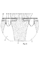
Fig. 2 is a vertical cross-section of a part of the embodiment ofFig. 1 on a larger scale. -
Fig. 3 is an enlarged perspective view of a rigid element of the stable floor element as shown inFig. 1 . -
Fig. 4 is an enlarged perspective view of an elastic element of the stable floor element as shown inFig. 1 . -
Fig. 5 is an enlarged perspective view of a part of a valve element of the stable floor element as shown inFig. 1 . -
Fig. 6 is a similar view asFig. 1 of an alternative embodiment on a smaller scale. -
Fig. 7 is an enlarged view of a part of the embodiment ofFig. 6 , indicated by reference sign VII inFig. 6 . -
Figs. 8-9 are enlarged perspective views of elastic elements of the embodiment of the stable floor element as shown inFig. 6 . -
Fig. 10 is a similar view asFig. 2 of still another alternative embodiment. -
Fig. 1 shows an embodiment of a stable floor element 1, which comprises a grating and is mainly made of concrete. A number of similar stable floor elements 1 can be installed adjacent to each other to form a walking surface for animals in a stable. For example, the floor elements 1 may be located at a transport location in a stable for safe and comfortable motion without slipping. - The stable floor element 1 comprises six parallel
longitudinal beams 2 which are fixed to each other viacross beams 3. Elongatedgaps 4 extend between neighbouringlongitudinal beams 2. Thelongitudinal beams 2 and thecross beams 3 have concrete cores C which are integral and made by means of a concrete moulding process. The concrete cores C of thelongitudinal beams 2 are tapered downwardly such that thegaps 4 widen in that direction. In practice, the stable floor element 1 is mounted on a structure including a slurry storage such that excrements from the animals can be drained via thegaps 4 into the slurry storage. - The concrete cores C of the
longitudinal beams 2 have respectivetop sides 5, seeFig. 2 . Thetop side 5 of the concrete core C of thebeam 2 is substantially flat in this case and covered with atop layer 6 which prevents thetop side 5 from direct contact with excrements of animals. Thetop layer 6 is provided with arigid element 7 and anelastic element 8. Therigid element 7 is located in the centre of thebeam 2 as seen in transverse direction thereof. Therigid element 7 is made of a plastic composite and theelastic element 8 is made of rubber. Alternative materials are conceivable as long as therigid element 7 is less flexible than theelastic element 8. Bothelements Figs. 3, 4 , respectively. - The
elastic element 8 comprises two rectangular through-holes which are aligned in longitudinal direction of thebeam 2. Each hole is suitable for accommodating onerigid element 7. The rectangular holes may be created by means of laser cutting, for example. In the embodiment as shown inFig. 1 eachlongitudinal beam 2 comprises tworigid elements 7 and oneelastic element 8 between two neighbouringparallel cross beams 3, but the number and dimensions may be different in alternative embodiments. -
Figs. 2 and3 show that oppositeouter side walls rigid element 7 are tapered in a direction from anupper side 11 of therigid element 7 towards the concrete core C of thebeam 2, i.e. downwardly. Similarly, oppositeinner side walls elastic element 8 are also tapered in a direction from an upper side of theelastic element 8 towards the concrete core C of thebeam 2.Fig. 2 shows that theouter side walls rigid element 7 cooperate with theinner side walls elastic element 8. - The
rigid element 7 is fixed to the concrete core C of thebeam 2 by means of screws throughholes 14 in therigid element 7, but numerous alternative fixing means are conceivable. The heads of the screws are buried into therigid element 7 in order to minimize the risk of animals hurting themselves on an exposed screw. The respective tapered cooperatingedges elastic element 8 to be snap-locked to therigid element 7. In a condition as shown inFig. 2 a portion of alower side 15 of theelastic element 8 rests on thetop side 5 of the concrete core C of thebeam 2. - When installing the
top layer 6 on the concrete core of thebeam 2, therigid element 7 can be fixed to the concrete core C at first, after which theelastic element 8 is bent about a longitudinal axis such that theinner side walls lower side 15 move away from each other. Subsequently, theelastic element 8 can be put downwardly over therigid element 7. After relieving theelastic element 8 the cooperatingside walls rigid element 7 and theinner side walls elastic element 8 keep theelastic element 8 in place. - As seen from above, the
elastic element 8 envelopes therigid element 7, such that in vertical cross section, as shown inFig. 2 , theelastic element 8 is located at opposite sides of therigid element 7. Theelastic element 8 also abuts ends of therigid element 7 in longitudinal direction thereof. It is conceivable that at these ends contact surfaces of the rigid andelastic element - The
elastic element 8 has anupper surface 16 which comprisesgrooves 17 extending transversely with respect to the longitudinal direction of thebeam 2. Thegrooves 17 have bottom surfaces which are inclined downwardly in the direction of theadjacent gaps 4 between thebeams 2 in order to optimize draining away urine from the animals and minimize danger of slipping. Theupper side 11 of therigid element 7 is provided with grooves in longitudinal direction and transversal direction so as to create a certain level of roughness, seeFig. 3 . It is noted that theupper side 11 of therigid element 7 is domed in order to improve flow of urine towards thegaps 4. Furthermore, theupper surface 16 of theelastic element 8 may be slightly higher than theupper side 11 of therigid element 7, but in that case the bottom surfaces of thegrooves 17 may extend below theupper side 11 of therigid element 7. -
Fig. 5 shows a part of avalve element 18 which is located at thegap 4 between twoadjacent beams 2. Thevalve element 18 is a self-closing valve including opposite spring strips 19. The spring strips 19 have longitudinal hinges and normally contact each other in order to close thegaps 4. For clarity reasons,Fig. 2 shows a small gap between the cooperating spring strips 19. - The
valve element 18 only opens if a certain load falls onto the spring strips 19. Thevalve element 18 is provided withflanges 20 which are sandwiched between theelastic element 8 and the concrete core C of thebeam 2, as shown inFig. 2 . Theflange 20 may surround theentire gap 4 such that opposite end portions of theflanges 20 in longitudinal direction of thegap 4 rest on the concrete cores C of the cross beams 3.Fig. 2 shows that theelastic element 8 partly rests on thetop side 5 of the concrete core C of thebeam 2 and partly rests on theflanges 20, but it is also conceivable that theelastic element 8 entirely rests on theflanges 20. -
Fig. 1 shows that thetop layer 6 also covers the concrete cores C of the cross beams 3. In this case thetop layer 6 at the cross beams 3 mainly comprises an elongate rigid element which has different dimensions than therigid elements 7 of thelongitudinal beams 2. -
Fig. 6 shows an alternative embodiment of the stable floor element 1 andFig. 7 shows a part thereof in detail. The alternative embodiment also comprises parallellongitudinal beams 2,cross beams 3 andelongated gaps 4 between neighbouringlongitudinal beams 2. Thetop layer 6 is also provided withrigid elements 7 andelastic elements elastic elements elastic elements 8 of the embodiment as shown inFigs. 1-5 .Fig. 9 shows a type of theelastic element 21 which is applied at opposite end portions of the stable floor element 1 in longitudinal direction, whereasFig. 8 shows a type of theelastic element 22 which is applied between the opposite end portions. An advantaged of these types ofelastic elements rigid elements 7 of a plurality ofbeams 2. In fact a number of separateelastic elements 4 as shown inFig. 4 are interconnected by portions of theelastic elements gaps 4 in longitudinal direction. -
Fig. 10 shows still another embodiment of the stable floor element 1 according to the invention. In this case thebeams 2 are not provided with separate rigid elements as shown and described hereinbefore.Fig. 10 shows that thetop side 5 of the concrete core C is provided with anelevated portion 23, which forms a rigid region, comparable to therigid element 7 in the embodiment as shown inFig. 2 . Theupper side 11 of theelevated portion 23 is free of a covering such that thetop side 5 of the concrete core C coincides with theupper side 11 of theelevated portion 23 in this embodiment. Theelastic element 8 envelopes theelevated portion 23 and may be formed as shown inFig. 4 orFigs. 8 and 9 , or the like. -
Fig. 10 shows that theouter side walls elevated portion 23 cooperate with theinner side walls elastic element 8, but the cooperating side walls are not tapered in this case because of the moulding process of the concrete cores C of the stable floor element 1. - The invention is not limited to the embodiments shown in the drawings and described hereinbefore, which may be varied in different manners within the scope of the claims and their technical equivalents. For example, the rigid elements may be attached to the concrete core of the beams upon manufacturing, i.e. during moulding and curing the concrete core instead of by screwing them to the cured concrete cores.
Claims (15)
- A stable floor element (1), comprising at least two beams (2) which are spaced from each other, wherein each of the beams (2) has a concrete core (C) including a top side (5) which is covered with a top layer (6) that is provided with at least a rigid region (7) and an elastic region (8) which are adjacent to each other in a direction parallel to the top side (5), wherein upper sides (11, 16) of the regions (7, 8) form a common upper surface of the stable floor element (1).
- A stable floor element (1) according to claim 1, wherein the regions (7, 8) are formed from separate elements.
- A stable floor element (1) according to claim 1 or 2, wherein elastic regions (8) extend at opposite sides of the rigid region (7).
- A stable floor element (1) according to claim 2 and 3, wherein the elastic regions are formed by a common elastic element (8) that at least partly envelopes the rigid element (7).
- A stable floor element according to claim 4, wherein the rigid element (7) is fixed to the concrete core (C) and the elastic element (8) is snap-locked to the rigid element (7).
- A stable floor element (1) according to claim 5, wherein opposite side walls (9, 10) of the rigid element (7) and cooperating opposite inner side walls (12, 13) of the elastic element (8) are tapered in a direction from their upper sides (11, 16) towards the concrete core (C) of the beam (2).
- A stable floor element (1), comprising at least two beams (2) which are spaced from each other, wherein each of the beams (2) has a concrete core (C) including a top side (5) which is provided with an elevated portion (23), thus forming a rigid region, wherein elastic members (8) are located adjacent to the elevated portion (23) at opposite sides thereof, thus forming elastic regions, wherein the elastic members (8) are fixed to each other and wherein the upper sides (11, 16) of the elevated portion (23) and the elastic members (8) form a common upper surface of the stable floor element (1).
- A stable floor element (1) according to claim 7, wherein the elastic members are formed by a common elastic element (8) which at least partly envelopes the elevated portion (23).
- A stable floor element (1) according to claim 7 or 8, wherein the elastic members (8) extend at least up to opposite lateral edges of the beam (2).
- A stable floor element (1) according to one of the preceding claims, wherein the upper sides (11, 16) of the rigid and elastic regions (7, 8, 23) have different roughnesses.
- A stable floor element (1) according to one of the preceding claims, wherein the rigid region (7, 23) is elongated and its longitudinal direction is parallel to the longitudinal direction of the beam (2).
- A stable floor element (1) according to claim 11, wherein the rigid region (7, 23) is located in the centre of the beam (2) as seen in transverse direction of the beam (2).
- A stable floor element (1) according to one of the preceding claims, wherein a gap (4) between neighbouring beams (2) is provided with a valve element (18) for closing the gap (4) having flanges (20) which are at least partly sandwiched between the elastic regions (8) and the concrete cores (C) of the respective beams (2).
- A stable floor element (1) according to claim 13, wherein the valve element (18) comprises parallel spring strips (19).
- A stable floor element (1) according to one of the preceding claims, wherein the upper surface of the stable floor element (1) comprises grooves (17) extending transversely with respect to the longitudinal direction of the beams (2).
Priority Applications (2)
| Application Number | Priority Date | Filing Date | Title |
|---|---|---|---|
| DK14165939.1T DK2936977T3 (en) | 2014-04-25 | 2014-04-25 | Stable Floor element |
| EP14165939.1A EP2936977B1 (en) | 2014-04-25 | 2014-04-25 | A stable floor element |
Applications Claiming Priority (1)
| Application Number | Priority Date | Filing Date | Title |
|---|---|---|---|
| EP14165939.1A EP2936977B1 (en) | 2014-04-25 | 2014-04-25 | A stable floor element |
Publications (2)
| Publication Number | Publication Date |
|---|---|
| EP2936977A1 true EP2936977A1 (en) | 2015-10-28 |
| EP2936977B1 EP2936977B1 (en) | 2017-02-15 |
Family
ID=50639269
Family Applications (1)
| Application Number | Title | Priority Date | Filing Date |
|---|---|---|---|
| EP14165939.1A Active EP2936977B1 (en) | 2014-04-25 | 2014-04-25 | A stable floor element |
Country Status (2)
| Country | Link |
|---|---|
| EP (1) | EP2936977B1 (en) |
| DK (1) | DK2936977T3 (en) |
Cited By (2)
| Publication number | Priority date | Publication date | Assignee | Title |
|---|---|---|---|---|
| EP4046482A1 (en) | 2021-02-17 | 2022-08-24 | Lely Patent N.V. | Floor system for an animal shed |
| EP4385320A1 (en) * | 2022-12-15 | 2024-06-19 | Vdv R&D Bv | Insert element for a stable floor element |
Families Citing this family (1)
| Publication number | Priority date | Publication date | Assignee | Title |
|---|---|---|---|---|
| SI3647010T1 (en) | 2018-10-30 | 2021-04-30 | Betonwerk Schwarz Gmbh | Method for the production of a stall floor element |
Citations (4)
| Publication number | Priority date | Publication date | Assignee | Title |
|---|---|---|---|---|
| US3455279A (en) * | 1966-10-13 | 1969-07-15 | Rita R Krevit | Floor member for animal barn |
| DE202008008274U1 (en) * | 2008-06-20 | 2009-10-29 | Gummiwerk Kraiburg Elastik Gmbh | Floor covering assembly for animal stables |
| WO2009136376A1 (en) * | 2008-05-09 | 2009-11-12 | Van Der Velden Beton, Naamloze Vennootschap | Stable floor element |
| WO2012004717A1 (en) * | 2010-07-09 | 2012-01-12 | Vdv R&D Bvba | Stable floor element |
-
2014
- 2014-04-25 EP EP14165939.1A patent/EP2936977B1/en active Active
- 2014-04-25 DK DK14165939.1T patent/DK2936977T3/en active
Patent Citations (4)
| Publication number | Priority date | Publication date | Assignee | Title |
|---|---|---|---|---|
| US3455279A (en) * | 1966-10-13 | 1969-07-15 | Rita R Krevit | Floor member for animal barn |
| WO2009136376A1 (en) * | 2008-05-09 | 2009-11-12 | Van Der Velden Beton, Naamloze Vennootschap | Stable floor element |
| DE202008008274U1 (en) * | 2008-06-20 | 2009-10-29 | Gummiwerk Kraiburg Elastik Gmbh | Floor covering assembly for animal stables |
| WO2012004717A1 (en) * | 2010-07-09 | 2012-01-12 | Vdv R&D Bvba | Stable floor element |
Cited By (4)
| Publication number | Priority date | Publication date | Assignee | Title |
|---|---|---|---|---|
| EP4046482A1 (en) | 2021-02-17 | 2022-08-24 | Lely Patent N.V. | Floor system for an animal shed |
| NL2027577A (en) | 2021-02-17 | 2022-09-14 | Lely Patent Nv | Animal stable floor system |
| EP4385320A1 (en) * | 2022-12-15 | 2024-06-19 | Vdv R&D Bv | Insert element for a stable floor element |
| BE1031140B1 (en) * | 2022-12-15 | 2024-07-15 | Vdv R&D | Insertion element for a stable floor element |
Also Published As
| Publication number | Publication date |
|---|---|
| DK2936977T3 (en) | 2017-05-15 |
| EP2936977B1 (en) | 2017-02-15 |
Similar Documents
| Publication | Publication Date | Title |
|---|---|---|
| KR101689543B1 (en) | Deck board assembly | |
| EP2936977B1 (en) | A stable floor element | |
| BE1019414A5 (en) | STABLE FLOOR ELEMENT. | |
| EP3162196B1 (en) | A grooved floor element for a cowshed, a substrate and a flexible mat | |
| US9566462B2 (en) | Padded pole vault plant box | |
| KR200466046Y1 (en) | Connective device of wooddeck | |
| KR101219326B1 (en) | High strength panel of synthetic resin material | |
| US10674701B2 (en) | Agricultural mat and associated systems and methods | |
| KR102028889B1 (en) | sliding rail insert type deck assembly system | |
| US20060124074A1 (en) | Livestock flooring cover | |
| KR101414801B1 (en) | Composite girder | |
| KR102023868B1 (en) | Deck of wood bridge having corrosion resistant | |
| KR101761553B1 (en) | Grating Cover | |
| JP7224041B2 (en) | Grating and drainage unit | |
| KR101293164B1 (en) | Gutters means, which includes wooden deck walkway | |
| JP2010159586A (en) | Structure of section around earthen floor and construction method for the same | |
| US9528240B2 (en) | Safety edge sports channel | |
| US9725854B2 (en) | Railway ail fastening assembly and method | |
| KR102020671B1 (en) | deck assembly system with base single body type sliding rail | |
| CA2076303A1 (en) | Animal shelter flooring apparatus | |
| FR3049162A1 (en) | FLOOR COATING FOR AN ENCLOSURE | |
| RU2016129940A (en) | ASSEMBLY FORMWORK ELEMENT, OBTAINED FORMWORK AND METHOD FOR PRODUCING A BUILDING PLATE, INCLUDING A THROUGH PASS, LIMITED TO THIS FORMWORK | |
| JP7260109B2 (en) | Ground type septic tank | |
| KR200426112Y1 (en) | Prefabricated wall member for walking exercise facility | |
| RU113759U1 (en) | COATING ELEMENT AND COVERING OF THESE ELEMENTS |
Legal Events
| Date | Code | Title | Description |
|---|---|---|---|
| PUAI | Public reference made under article 153(3) epc to a published international application that has entered the european phase |
Free format text: ORIGINAL CODE: 0009012 |
|
| AK | Designated contracting states |
Kind code of ref document: A1 Designated state(s): AL AT BE BG CH CY CZ DE DK EE ES FI FR GB GR HR HU IE IS IT LI LT LU LV MC MK MT NL NO PL PT RO RS SE SI SK SM TR |
|
| AX | Request for extension of the european patent |
Extension state: BA ME |
|
| 17P | Request for examination filed |
Effective date: 20160426 |
|
| RBV | Designated contracting states (corrected) |
Designated state(s): AL AT BE BG CH CY CZ DE DK EE ES FI FR GB GR HR HU IE IS IT LI LT LU LV MC MK MT NL NO PL PT RO RS SE SI SK SM TR |
|
| RIC1 | Information provided on ipc code assigned before grant |
Ipc: A01K 1/015 20060101AFI20160728BHEP |
|
| GRAP | Despatch of communication of intention to grant a patent |
Free format text: ORIGINAL CODE: EPIDOSNIGR1 |
|
| INTG | Intention to grant announced |
Effective date: 20160927 |
|
| GRAS | Grant fee paid |
Free format text: ORIGINAL CODE: EPIDOSNIGR3 |
|
| GRAA | (expected) grant |
Free format text: ORIGINAL CODE: 0009210 |
|
| AK | Designated contracting states |
Kind code of ref document: B1 Designated state(s): AL AT BE BG CH CY CZ DE DK EE ES FI FR GB GR HR HU IE IS IT LI LT LU LV MC MK MT NL NO PL PT RO RS SE SI SK SM TR |
|
| REG | Reference to a national code |
Ref country code: CH Ref legal event code: EP Ref country code: GB Ref legal event code: FG4D |
|
| REG | Reference to a national code |
Ref country code: IE Ref legal event code: FG4D |
|
| REG | Reference to a national code |
Ref country code: AT Ref legal event code: REF Ref document number: 867367 Country of ref document: AT Kind code of ref document: T Effective date: 20170315 |
|
| REG | Reference to a national code |
Ref country code: DE Ref legal event code: R096 Ref document number: 602014006760 Country of ref document: DE |
|
| REG | Reference to a national code |
Ref country code: NL Ref legal event code: FP |
|
| REG | Reference to a national code |
Ref country code: DK Ref legal event code: T3 Effective date: 20170511 |
|
| REG | Reference to a national code |
Ref country code: FR Ref legal event code: PLFP Year of fee payment: 4 |
|
| REG | Reference to a national code |
Ref country code: LT Ref legal event code: MG4D |
|
| PG25 | Lapsed in a contracting state [announced via postgrant information from national office to epo] |
Ref country code: NO Free format text: LAPSE BECAUSE OF FAILURE TO SUBMIT A TRANSLATION OF THE DESCRIPTION OR TO PAY THE FEE WITHIN THE PRESCRIBED TIME-LIMIT Effective date: 20170515 Ref country code: LT Free format text: LAPSE BECAUSE OF FAILURE TO SUBMIT A TRANSLATION OF THE DESCRIPTION OR TO PAY THE FEE WITHIN THE PRESCRIBED TIME-LIMIT Effective date: 20170215 Ref country code: GR Free format text: LAPSE BECAUSE OF FAILURE TO SUBMIT A TRANSLATION OF THE DESCRIPTION OR TO PAY THE FEE WITHIN THE PRESCRIBED TIME-LIMIT Effective date: 20170516 Ref country code: HR Free format text: LAPSE BECAUSE OF FAILURE TO SUBMIT A TRANSLATION OF THE DESCRIPTION OR TO PAY THE FEE WITHIN THE PRESCRIBED TIME-LIMIT Effective date: 20170215 |
|
| PG25 | Lapsed in a contracting state [announced via postgrant information from national office to epo] |
Ref country code: LV Free format text: LAPSE BECAUSE OF FAILURE TO SUBMIT A TRANSLATION OF THE DESCRIPTION OR TO PAY THE FEE WITHIN THE PRESCRIBED TIME-LIMIT Effective date: 20170215 Ref country code: PT Free format text: LAPSE BECAUSE OF FAILURE TO SUBMIT A TRANSLATION OF THE DESCRIPTION OR TO PAY THE FEE WITHIN THE PRESCRIBED TIME-LIMIT Effective date: 20170615 Ref country code: RS Free format text: LAPSE BECAUSE OF FAILURE TO SUBMIT A TRANSLATION OF THE DESCRIPTION OR TO PAY THE FEE WITHIN THE PRESCRIBED TIME-LIMIT Effective date: 20170215 Ref country code: SE Free format text: LAPSE BECAUSE OF FAILURE TO SUBMIT A TRANSLATION OF THE DESCRIPTION OR TO PAY THE FEE WITHIN THE PRESCRIBED TIME-LIMIT Effective date: 20170215 Ref country code: ES Free format text: LAPSE BECAUSE OF FAILURE TO SUBMIT A TRANSLATION OF THE DESCRIPTION OR TO PAY THE FEE WITHIN THE PRESCRIBED TIME-LIMIT Effective date: 20170215 Ref country code: BG Free format text: LAPSE BECAUSE OF FAILURE TO SUBMIT A TRANSLATION OF THE DESCRIPTION OR TO PAY THE FEE WITHIN THE PRESCRIBED TIME-LIMIT Effective date: 20170515 |
|
| PG25 | Lapsed in a contracting state [announced via postgrant information from national office to epo] |
Ref country code: RO Free format text: LAPSE BECAUSE OF FAILURE TO SUBMIT A TRANSLATION OF THE DESCRIPTION OR TO PAY THE FEE WITHIN THE PRESCRIBED TIME-LIMIT Effective date: 20170215 Ref country code: SK Free format text: LAPSE BECAUSE OF FAILURE TO SUBMIT A TRANSLATION OF THE DESCRIPTION OR TO PAY THE FEE WITHIN THE PRESCRIBED TIME-LIMIT Effective date: 20170215 Ref country code: IT Free format text: LAPSE BECAUSE OF FAILURE TO SUBMIT A TRANSLATION OF THE DESCRIPTION OR TO PAY THE FEE WITHIN THE PRESCRIBED TIME-LIMIT Effective date: 20170215 Ref country code: CZ Free format text: LAPSE BECAUSE OF FAILURE TO SUBMIT A TRANSLATION OF THE DESCRIPTION OR TO PAY THE FEE WITHIN THE PRESCRIBED TIME-LIMIT Effective date: 20170215 Ref country code: EE Free format text: LAPSE BECAUSE OF FAILURE TO SUBMIT A TRANSLATION OF THE DESCRIPTION OR TO PAY THE FEE WITHIN THE PRESCRIBED TIME-LIMIT Effective date: 20170215 |
|
| REG | Reference to a national code |
Ref country code: DE Ref legal event code: R097 Ref document number: 602014006760 Country of ref document: DE |
|
| PG25 | Lapsed in a contracting state [announced via postgrant information from national office to epo] |
Ref country code: SM Free format text: LAPSE BECAUSE OF FAILURE TO SUBMIT A TRANSLATION OF THE DESCRIPTION OR TO PAY THE FEE WITHIN THE PRESCRIBED TIME-LIMIT Effective date: 20170215 Ref country code: PL Free format text: LAPSE BECAUSE OF FAILURE TO SUBMIT A TRANSLATION OF THE DESCRIPTION OR TO PAY THE FEE WITHIN THE PRESCRIBED TIME-LIMIT Effective date: 20170215 |
|
| REG | Reference to a national code |
Ref country code: CH Ref legal event code: PL |
|
| PLBE | No opposition filed within time limit |
Free format text: ORIGINAL CODE: 0009261 |
|
| STAA | Information on the status of an ep patent application or granted ep patent |
Free format text: STATUS: NO OPPOSITION FILED WITHIN TIME LIMIT |
|
| 26N | No opposition filed |
Effective date: 20171116 |
|
| PG25 | Lapsed in a contracting state [announced via postgrant information from national office to epo] |
Ref country code: MC Free format text: LAPSE BECAUSE OF FAILURE TO SUBMIT A TRANSLATION OF THE DESCRIPTION OR TO PAY THE FEE WITHIN THE PRESCRIBED TIME-LIMIT Effective date: 20170215 |
|
| PG25 | Lapsed in a contracting state [announced via postgrant information from national office to epo] |
Ref country code: LU Free format text: LAPSE BECAUSE OF NON-PAYMENT OF DUE FEES Effective date: 20170425 Ref country code: SI Free format text: LAPSE BECAUSE OF FAILURE TO SUBMIT A TRANSLATION OF THE DESCRIPTION OR TO PAY THE FEE WITHIN THE PRESCRIBED TIME-LIMIT Effective date: 20170215 Ref country code: CH Free format text: LAPSE BECAUSE OF NON-PAYMENT OF DUE FEES Effective date: 20170430 Ref country code: LI Free format text: LAPSE BECAUSE OF NON-PAYMENT OF DUE FEES Effective date: 20170430 |
|
| REG | Reference to a national code |
Ref country code: FR Ref legal event code: PLFP Year of fee payment: 5 |
|
| PG25 | Lapsed in a contracting state [announced via postgrant information from national office to epo] |
Ref country code: MT Free format text: LAPSE BECAUSE OF NON-PAYMENT OF DUE FEES Effective date: 20170425 |
|
| PG25 | Lapsed in a contracting state [announced via postgrant information from national office to epo] |
Ref country code: HU Free format text: LAPSE BECAUSE OF FAILURE TO SUBMIT A TRANSLATION OF THE DESCRIPTION OR TO PAY THE FEE WITHIN THE PRESCRIBED TIME-LIMIT; INVALID AB INITIO Effective date: 20140425 |
|
| REG | Reference to a national code |
Ref country code: AT Ref legal event code: UEP Ref document number: 867367 Country of ref document: AT Kind code of ref document: T Effective date: 20170215 |
|
| PG25 | Lapsed in a contracting state [announced via postgrant information from national office to epo] |
Ref country code: CY Free format text: LAPSE BECAUSE OF FAILURE TO SUBMIT A TRANSLATION OF THE DESCRIPTION OR TO PAY THE FEE WITHIN THE PRESCRIBED TIME-LIMIT Effective date: 20170215 |
|
| PG25 | Lapsed in a contracting state [announced via postgrant information from national office to epo] |
Ref country code: MK Free format text: LAPSE BECAUSE OF FAILURE TO SUBMIT A TRANSLATION OF THE DESCRIPTION OR TO PAY THE FEE WITHIN THE PRESCRIBED TIME-LIMIT Effective date: 20170215 |
|
| PG25 | Lapsed in a contracting state [announced via postgrant information from national office to epo] |
Ref country code: TR Free format text: LAPSE BECAUSE OF FAILURE TO SUBMIT A TRANSLATION OF THE DESCRIPTION OR TO PAY THE FEE WITHIN THE PRESCRIBED TIME-LIMIT Effective date: 20170215 |
|
| PG25 | Lapsed in a contracting state [announced via postgrant information from national office to epo] |
Ref country code: AL Free format text: LAPSE BECAUSE OF FAILURE TO SUBMIT A TRANSLATION OF THE DESCRIPTION OR TO PAY THE FEE WITHIN THE PRESCRIBED TIME-LIMIT Effective date: 20170215 Ref country code: IS Free format text: LAPSE BECAUSE OF FAILURE TO SUBMIT A TRANSLATION OF THE DESCRIPTION OR TO PAY THE FEE WITHIN THE PRESCRIBED TIME-LIMIT Effective date: 20170615 |
|
| P01 | Opt-out of the competence of the unified patent court (upc) registered |
Effective date: 20230505 |
|
| PGFP | Annual fee paid to national office [announced via postgrant information from national office to epo] |
Ref country code: IE Payment date: 20230427 Year of fee payment: 10 Ref country code: FR Payment date: 20230425 Year of fee payment: 10 Ref country code: DK Payment date: 20230427 Year of fee payment: 10 |
|
| PGFP | Annual fee paid to national office [announced via postgrant information from national office to epo] |
Ref country code: FI Payment date: 20230425 Year of fee payment: 10 Ref country code: AT Payment date: 20230403 Year of fee payment: 10 |
|
| PGFP | Annual fee paid to national office [announced via postgrant information from national office to epo] |
Ref country code: GB Payment date: 20230427 Year of fee payment: 10 |
|
| REG | Reference to a national code |
Ref country code: DK Ref legal event code: EBP Effective date: 20240430 |
|
| REG | Reference to a national code |
Ref country code: AT Ref legal event code: MM01 Ref document number: 867367 Country of ref document: AT Kind code of ref document: T Effective date: 20240425 |
|
| GBPC | Gb: european patent ceased through non-payment of renewal fee |
Effective date: 20240425 |
|
| PG25 | Lapsed in a contracting state [announced via postgrant information from national office to epo] |
Ref country code: FI Free format text: LAPSE BECAUSE OF NON-PAYMENT OF DUE FEES Effective date: 20240425 |
|
| PG25 | Lapsed in a contracting state [announced via postgrant information from national office to epo] |
Ref country code: GB Free format text: LAPSE BECAUSE OF NON-PAYMENT OF DUE FEES Effective date: 20240425 |
|
| PG25 | Lapsed in a contracting state [announced via postgrant information from national office to epo] |
Ref country code: FR Free format text: LAPSE BECAUSE OF NON-PAYMENT OF DUE FEES Effective date: 20240430 |
|
| PG25 | Lapsed in a contracting state [announced via postgrant information from national office to epo] |
Ref country code: AT Free format text: LAPSE BECAUSE OF NON-PAYMENT OF DUE FEES Effective date: 20240425 |
|
| PG25 | Lapsed in a contracting state [announced via postgrant information from national office to epo] |
Ref country code: GB Free format text: LAPSE BECAUSE OF NON-PAYMENT OF DUE FEES Effective date: 20240425 Ref country code: FR Free format text: LAPSE BECAUSE OF NON-PAYMENT OF DUE FEES Effective date: 20240430 Ref country code: FI Free format text: LAPSE BECAUSE OF NON-PAYMENT OF DUE FEES Effective date: 20240425 Ref country code: AT Free format text: LAPSE BECAUSE OF NON-PAYMENT OF DUE FEES Effective date: 20240425 |
|
| PG25 | Lapsed in a contracting state [announced via postgrant information from national office to epo] |
Ref country code: DK Free format text: LAPSE BECAUSE OF NON-PAYMENT OF DUE FEES Effective date: 20240430 |
|
| PG25 | Lapsed in a contracting state [announced via postgrant information from national office to epo] |
Ref country code: IE Free format text: LAPSE BECAUSE OF NON-PAYMENT OF DUE FEES Effective date: 20240425 |
|
| PGFP | Annual fee paid to national office [announced via postgrant information from national office to epo] |
Ref country code: NL Payment date: 20250427 Year of fee payment: 12 |
|
| PGFP | Annual fee paid to national office [announced via postgrant information from national office to epo] |
Ref country code: DE Payment date: 20250429 Year of fee payment: 12 |
|
| PGFP | Annual fee paid to national office [announced via postgrant information from national office to epo] |
Ref country code: BE Payment date: 20250428 Year of fee payment: 12 |