EP2936047B1 - Verfahren zum bestimmen der krümmung einer deformierbaren rohrstruktur des typs öl offshoreleitung und deformierbare rohrstruktur des typs öl offshoreleitung. - Google Patents
Verfahren zum bestimmen der krümmung einer deformierbaren rohrstruktur des typs öl offshoreleitung und deformierbare rohrstruktur des typs öl offshoreleitung. Download PDFInfo
- Publication number
- EP2936047B1 EP2936047B1 EP13808055.1A EP13808055A EP2936047B1 EP 2936047 B1 EP2936047 B1 EP 2936047B1 EP 13808055 A EP13808055 A EP 13808055A EP 2936047 B1 EP2936047 B1 EP 2936047B1
- Authority
- EP
- European Patent Office
- Prior art keywords
- accelerometers
- measurement
- sin
- objects
- inclination
- Prior art date
- Legal status (The legal status is an assumption and is not a legal conclusion. Google has not performed a legal analysis and makes no representation as to the accuracy of the status listed.)
- Active
Links
Images

Classifications
-
- G—PHYSICS
- G01—MEASURING; TESTING
- G01B—MEASURING LENGTH, THICKNESS OR SIMILAR LINEAR DIMENSIONS; MEASURING ANGLES; MEASURING AREAS; MEASURING IRREGULARITIES OF SURFACES OR CONTOURS
- G01B5/00—Measuring arrangements characterised by the use of mechanical techniques
- G01B5/24—Measuring arrangements characterised by the use of mechanical techniques for measuring angles or tapers; for testing the alignment of axes
-
- G—PHYSICS
- G01—MEASURING; TESTING
- G01B—MEASURING LENGTH, THICKNESS OR SIMILAR LINEAR DIMENSIONS; MEASURING ANGLES; MEASURING AREAS; MEASURING IRREGULARITIES OF SURFACES OR CONTOURS
- G01B5/00—Measuring arrangements characterised by the use of mechanical techniques
- G01B5/004—Measuring arrangements characterised by the use of mechanical techniques for measuring coordinates of points
-
- G—PHYSICS
- G01—MEASURING; TESTING
- G01B—MEASURING LENGTH, THICKNESS OR SIMILAR LINEAR DIMENSIONS; MEASURING ANGLES; MEASURING AREAS; MEASURING IRREGULARITIES OF SURFACES OR CONTOURS
- G01B7/00—Measuring arrangements characterised by the use of electric or magnetic techniques
- G01B7/28—Measuring arrangements characterised by the use of electric or magnetic techniques for measuring contours or curvatures
-
- G—PHYSICS
- G01—MEASURING; TESTING
- G01P—MEASURING LINEAR OR ANGULAR SPEED, ACCELERATION, DECELERATION, OR SHOCK; INDICATING PRESENCE, ABSENCE, OR DIRECTION, OF MOVEMENT
- G01P15/00—Measuring acceleration; Measuring deceleration; Measuring shock, i.e. sudden change of acceleration
-
- G—PHYSICS
- G01—MEASURING; TESTING
- G01V—GEOPHYSICS; GRAVITATIONAL MEASUREMENTS; DETECTING MASSES OR OBJECTS; TAGS
- G01V7/00—Measuring gravitational fields or waves; Gravimetric prospecting or detecting
Definitions
- the invention relates to a method for determining the curvature of a deformable tubular structure of the offshore oil pipe type.
- the invention also relates to a deformable tubular structure of the instrumented offshore oil pipe type comprising a device for determining its curvature.
- the present invention relates in particular to tubular structures, in particular tubular structures intended for the transport of hydrocarbons used at a distance from the coast.
- Such pipes are typically submarine pipes.
- the offshore exploitation of an oil or gas deposit located at great depth is generally made from a floating production system located on the surface, for example from a FPSO ("Floating Production Storage and Offloading") or of a floating oil platform.
- FPSO Floating Production Storage and Offloading
- these floating systems are not static and move under the effect of currents, swells, waves and wind. Consequently, the submarine pipes used to lift the oil from the seabed to the surface must be able to deform to accommodate the movements of the floating system.
- the document WO2009 / 109745 describes the use of an inclinometer fixed on the pipe and a positioning system fixed on the floating support.
- the document describes the determination of the relative inclination of driving by compared to floating support.
- this document does not provide any detailed information on the inclination measurement, nor on how to determine the curvature from the measurements made.
- the document GB2086055 describes a device for calculating the trajectory of an underground borehole, comprising a probe traversing the interior of the borehole.
- the document FR2610100 describes a device for determining the deformations and the path of a pipeline, in the form of a vehicle traversing the interior of the pipeline.
- the document US2008 / 211808 describes a device comprising a set of connected sensors to match the shape of an object. Depending on the inclination of the sensors, the device calculates the shape of the object.
- the present invention aims to provide a reliable and robust solution for measuring the curvature of a tubular structure, making it possible to avoid having to access this tubular structure in a hostile environment.
- At least two accelerometers of each of said objects are distant.
- the resolution of the matrix equation during a determination of an inclination comprises the minimization of a criterion L ( ⁇ , ⁇ ) defined by the following equation:
- L ( ⁇ , ⁇ ) defined by the following equation:
- said accelerometers of each of said objects are at least four in number, are distributed over a circle and each have a measurement direction defined by the radius connecting this accelerometer to the center of the circle.
- said accelerometers are distributed uniformly over said circle.
- the accelerometers present a statistical Gaussian and centered measurement noise, the resolution comprising the minimization of a criterion L ( ⁇ , ⁇ ) defined by the following equation:
- the ⁇ ⁇ sin ⁇ f _ ⁇ - m _ T ⁇ ⁇ - 1 _ ⁇ sin ⁇ f _ ⁇ - m _ with f ( ⁇ ) a vector whose i-th component is equal to -sin ( ⁇ i + ⁇ ), with ⁇ a covariance matrix corresponding to the statistical measurement noises of the accelerometers for said measurement directions.
- the statistical noises of the accelerometers are statistically independent, and the covariance matrix ⁇ is a diagonal and definite positive matrix whose i-th coefficient is equal to the variance ⁇ i 2 for the i-th direction of measurement.
- said tubular structure has a maximum natural acceleration relative to the reference frame at least ten times less than the amplitude of the gravity field g, preferably at least twenty times less than the amplitude of the gravity field g during said measurements.
- said inclinations used for the determination of said curvature are based on simultaneous measurements of the accelerometers of the first and second objects.
- tubular structure covers both flexible pipes, rigid pipes and umbilicals used in the field of oil or gas exploitation, and on the other hand accessories of the stiffener or limiter type. curvature that can be fixed around pipes or umbilicals. These pipes can be flexible or rigid depending on the application.
- Offshore oil lines are generally used to transport hydrocarbons extracted from a deposit, but they can also be used to transport pressurized seawater intended to be injected into a deposit in order to increase the quantity of hydrocarbons extracted of the last.
- the internal diameter of these oil pipes is typically between 50mm and 500mm. They can be used at great depths (usually over 1000m) and are in this case designed to withstand very high external pressure.
- the pressure of the hydrocarbons transported is commonly greater than 10 MPa and can sometimes reach 100 MPa.
- the temperature of the transported hydrocarbons is sometimes higher than 100 ° C., for example of the order of 120 ° C.
- Flexible oil lines generally have a complex structure. They include at least one flexible tight tubular layer reinforced by at least one helically wound profile.
- the waterproof flexible tubular layer is a tube made of polymer material, and the reinforcing profiles are wires of steel or of composite material.
- Such flexible pipes are described in particular in the normative document API RP 17B “Recommended Practice for Flexible Pipe” published by the American Petroleum Institute . They are generally used in areas where great flexibility is required, especially in the very dynamic areas of risers.
- Rigid pipes are generally made by assembling by welding or screwing rigid tubular elements of very thick steel. They may also comprise other layers, in particular layers of thermal insulation or of protection against corrosion. Rigid pipes can also be made of composite material, for example from a thin waterproof tube reinforced by a liner of composite material. Rigid pipes are normally reserved for static applications, but they can also be used for certain weakly dynamic applications, in particular in combination with floating supports having high stability.
- Flexible cryogenic pipes are used to transport liquefied natural gas ("LNG” in French, “LNG” in English), typically from a liquefaction unit to a transport vessel or from a transport vessel to a storage unit.
- LNG liquefied natural gas
- the sealed flexible tubular layer of these flexible pipes is generally a thin corrugated metal tube.
- Umbilicals are tubular structures comprising several components, including at least one tube, the other components possibly being tubes, electrical cables, or fiber optic cables. The components are assembled together by helical winding which gives great flexibility to the assembly.
- the umbilicals are generally used to pilot from the surface of underwater installations of the wellhead, valve or pump type. They can also have other functions and in particular serve to inject fluids into petroleum lines facilitating the flow of petroleum or corrosion inhibitors.
- the umbilicals are notably described in the normative document API RP 17E “Specification for Subsea Umbilicals” published by the American Petroleum Institute .
- the method for determining the curvature of a tubular structure according to the present invention is based on inclination measurements which can be carried out only using accelerometers.
- the accelerometers are robust and economical sensors, which constitutes a first advantage of the invention.
- the method does not require any prior knowledge of the absolute angular position of the accelerometers relative to a reference frame, which avoids having to make such a calibration of the measurements once the tubular structure is installed on site.
- the tubular structures targeted by the present invention are generally very difficult to access once installed at sea. Consequently, a calibration of the inclination measurements based on a comparison with other reference measurements carried out on site after installation would be complex and prohibitive to implement. The elimination of such a calibration therefore constitutes a second advantage of the invention.
- the tilt measurements made according to the invention prove to be precise even for low tilt values, which makes it possible to determine a curvature and fatigue of a tube with great precision, which constitutes a third advantage of the invention.
- the figure 1 represents an instrumented object 2, comprising a device 4 configured to determine the inclination of the object 2 relative to a reference direction D.
- the reference direction D is the direction in which the gravity to which the l is subjected applies object 2.
- object 2 is subject to Earth's gravity
- the reference direction D is the direction of the earth's gravity field, represented by the vector g and defining a vertical direction.
- the object 2 is in the example a solid considered to be non-deformable, that is to say that the distance separating between them any points of the object 2 does not vary when this object 2 undergoes a displacement.
- This object 2 is here of cylindrical shape.
- this object 2 is drawn in dotted lines on the figure 1 (and on the figure 4 ).
- Object 2 can for example be produced in the form of a non-deformable collar intended to be fixed to a deformable tubular structure
- an orthonormal reference frame R is defined.
- This coordinate system R is composed of three orthonormal directions X, Y and Z.
- the vertical direction, denoted Z, is parallel to the direction D of the gravity field g in the example.
- the gravity field g will be expressed by the vector [0; 0; 1] in the reference frame R.
- the inclination of the object 2 is here defined as being the angle formed between the direction D and the axis U along which the object 2 extends. figure 1 , the object 2 is illustrated with a zero inclination, the directions D and U are therefore parallel.
- the device 4 comprises N accelerometers A 1 to A N , where N is an integer advantageously greater than or equal to three, four or seven or ten.
- These accelerometers are here mono-axial, that is to say that each accelerometer has only one measurement direction.
- These accelerometers A 1 to A N here have a built-in connection with the object 2.
- the object 2 here forms a rigid connection between the accelerometers A 1 to A N.
- the invention can of course also be implemented by including one or more accelerometers with 2 or 3 measurement directions among the accelerometers.
- Such accelerometers will be treated as several mono-axial accelerometers among the accelerometers A 1 to A N and each having a measurement direction.
- the i-th accelerometer is designated by the reference A i where i is an integer greater than or equal to 1 and less than or equal to N.
- the measurement direction of this i-th mono-axial accelerometer is denoted v i .
- reference will be made to this i-th accelerometer to designate general properties of said accelerometers.
- each of these accelerometers is materialized by a point location.
- the accelerometers A 1 , A 2 , A j and A N are illustrated.
- the acceleration measured by each of these accelerometers corresponds to the geometric projection of the gravity field g on the measurement direction of this accelerometer.
- v i The direction of measurement v i of any of the accelerometers A i is determined by the following equation, with coefficients a i, 1 , a i, 2 a i, 3 being coefficients known by assumption, invariant during the time due to the rigid connection between the accelerometers A 1 to A N.
- v i at i , 1 U + at i , 2 V + at i , 3 W
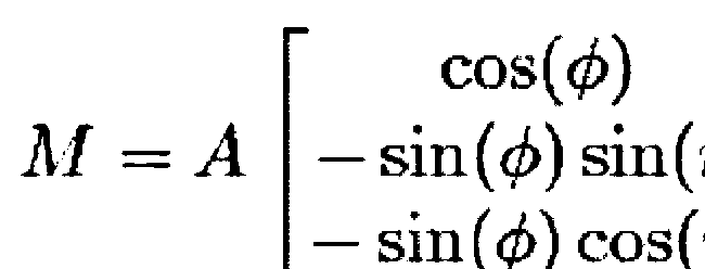
- m i v i T g, where T denotes the matrix transposition.
- M the vector [m 1 , ... m N ] T containing the different measurements of the accelerometers.
- the resolution of this matrix equation can be achieved by minimizing the following criterion:
- the ⁇ ⁇ ⁇ M - AT cos ⁇ - sin ⁇ sin ⁇ - sin ⁇ cos ⁇ ⁇ 2
- defining the Euclidean norm of three-dimensional vectors. This resolution remains valid even when the matrix equation of M is disturbed by uncertainty of amplitudes at least 10 times less than the amplitude of the gravity field g.
- Such a method of determining the inclination thus makes it possible to obtain good accuracy from the use of two measurement directions and this without a magnetometer. Such an inclination is obtained relative to the U axis, in any plane including this U axis. In addition, such a method makes it possible in practice to obtain a good accuracy in determining the inclination, from low values. inclination, which is useful for applications where the inclination varies within a relatively limited range. By comparison, a gyroscope does not provide a reliable measurement for a low tilt value and is sensitive to noise and the environment.
- the accelerometers are here positioned on a circle C, passing through each of the accelerometers and such that the measurement directions of the accelerometers are contained in the plane including this circle.
- the normal to the plane including the circle C coincides with the direction defined by the vector U.
- these accelerometers are accelerometers marketed by the company "Colibrys" under the commercial reference "MS9002".
- the measurement direction of the accelerometer A1 is chosen to be collinear with the axis V for this example.
- the measurement direction v i of the i-th accelerometer extends radially from the center of the circle C.
- This direction v i is here represented by a vector, the direction of which is a straight line passing through the point location of the i- th accelerometer and through the center of circle C.
- v i cos ⁇ i V + sin ⁇ i W
- ⁇ i the known positioning angle of the accelerometer A i relative to a reference accelerometer (A 1 in this example) around the axis U.
- M - sin ⁇ sin ⁇ 1 + ⁇ sin ⁇ 2 + ⁇ ... sin ⁇ NOT + ⁇
- the measurement signal m i is tainted with statistical noise for each of the accelerometers.
- each statistical noise is a Gaussian and centered statistical process, which corresponds to a good approximation of reality for a large number of accelerometers.
- the variance of this statistical noise, for the i-th accelerometer, is noted ⁇ i 2 .
- this matrix ⁇ is a diagonal and definite positive matrix, whose i-th diagonal coefficient is equal to the variance ⁇ i 2 of the i-th accelerometer.
- the resolution of the matrix equation can then be carried out by minimizing the following criterion:
- the ⁇ ⁇ sin ⁇ f _ ⁇ - m _ T ⁇ ⁇ - 1 _ ⁇ sin ⁇ f _ ⁇ - m _
- the computer 14 is in particular programmed to execute information contained on the support 12.
- the support 12 contains instructions for the execution of the process of the figure 3 .
- the interface 16 allows in particular the acquisition, by the computer 14, of the measurement values m (j) supplied by the accelerometers of the device 4.
- the interface 16 comprises a data bus, such as a serial bus (for “Sériai Peripheral Interface” in English), electrically connected to the accelerometers A 1 to A N.
- Object 2 can have a different shape.
- the inclination of the object 2 can be defined other than with respect to the axis U.
- the accelerometers are not necessarily all mono-axial.
- the accelerometers are tri-axial accelerometers, such as those sold by the company "STMicroelectronics" under the commercial reference "LSM303DLH”.
- the accelerometers of the device 4 can be placed differently from the object 2.
- these accelerometers can have a different spatial configuration than the circle C.
- An accelerometer may not present statistical noise.
- the noise b (j) is zero and the coefficients ⁇ j 2 which appear in the estimator L are fixed at 1.
- At least two objects 2 are combined to determine the curvature of a deformable tubular structure.
- the figure 5 represents for this purpose a portion of a deformable tubular structure 40 on which are placed instrumented objects 42 and 44, for example identical to object 2.
- Deformation properties of the structure 40 can thus be indirectly calculated from the inclination of each of the objects 42 and 44. It can be considered that the objects 42 and 44 are non-deformable relative to the tubular structure 40 if the deformations induced on these objects are negligible compared to the relative displacements between these objects, displacements due to the deformations of the tubular structure 40.
- the tubular structure 40 is deformable by bending.
- the objects 42 and 44 are here kept integral with the structure 40 by an embedding link.
- the objects 42 and 44 are for example rigid metallic collars tightened around the tubular structure 40.
- These objects 42 and 44 are for example connected, by a data bus, to a calculation unit configured to determine the curvature of a direction median 46 of the structure 40, from the inclinations measured simultaneously by each of the objects 42 and 44.
- this data bus and this calculation unit are not illustrated on the figure 5 .
- the inclination of these objects 42 and 44 is here defined relative to the direction of the gravity field g, here vertical.
- the computing device 10 may have a different shape.
- this device 10 is not necessarily incorporated into each of the objects 42, 44.
- a single device 10 can then be placed outside these objects 42, 44, in a data processing unit configured to receive the measurement data of the accelerometers of objects 42 and 44.
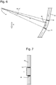
- FIGS. 6 and 7 represent the same portion of tubular structure 50 in two different positions.
- the tubular structure 50 is curved and locally has a radius of curvature equal to R.
- the tubular structure 50 is straight (infinite radius of curvature).
- non-deformable instrumented collars 54 and 56 are arranged, for example identical to object 2.
- the non-deformable instrumented collars 54, 56 are tightened around the tubular structure 50 so that they cannot slide along the latter when the latter is bent.
- the distance L separating the centers of the two collars 54, 56, distance measured along the axis of the tubular structure 50 is therefore constant and independent of the curvature of the tubular structure 50.
- R d ⁇ ds ⁇ ⁇ 2 - ⁇ 1
- the distance L separating the two collars 54, 56 is less than 1 meter, and preferably less than 50 centimeters.
- the information of the respective matrices A of the accelerometers of the two collars 54 and 56 are defined beforehand, possibly with the statistical noise properties of these accelerometers.
- the tubular structure 50 is in an initial position with a given configuration. Then, during a step 22, the tubular structure undergoes a deformation towards a new configuration. During this deformation, each collar 54 and 56 experiences a displacement from its initial position towards a position in which it has a new inclination relative to the reference direction D. For example, the collars 54 and 56 undergo respective rotations relative to the mark R. Here, at the end of these rotations, the collars 54 and 56 have respective angles of inclination denoted ⁇ 1 and ⁇ 2, which are not zero, with respect to the direction D ( Figure 4 ).
- each accelerometer provides a measure m i of acceleration.
- the tubular structure 50 is in a quasi-static state, since the determination of the inclinations uses a resolution based on the measurements of the gravity field g by the different accelerometers. It can be considered that the tubular structure 50 is in a quasi-static state when the natural acceleration (that is to say corresponding to the movement of the structure) of the tubular structure 50 relative to the reference frame R is at least ten times or twenty times or fifty times less than the amplitude of gravity g.
- the measurement is suitable for a tubular structure 50 whose normal conditions of use are of quasi-static type.
- step 30 the inclinations determined in step 26 are used to calculate the local curvature (between the collars 54 and 56) of the tubular structure 50.
- Steps in the process of figure 3 can be executed in a different order and / or can be simultaneous.
- the tubular structure 50 is not necessarily placed in an initial state having a zero inclination, but may have a non-zero inclination.
- the displacement (step 22) of the tubular structure 50 and the measurement of the accelerations (step 24) can be concomitant, provided that the tubular structure 50 remains quasi-static during its displacement.
- the invention is not limited to the case where rigid objects equipped with accelerometers and fixed in separate locations along the tubular structure are rigid collars tightened around the latter. These objects can also be embedded inside the tubular structure. Thus, for example, in the case where the tubular structure is a pipe, these objects can be embedded inside the wall of the pipe.
- rigid objects equipped with accelerometers can be either fixed around the stiffener, or embedded inside the stiffener, or fixed around the pipe at the stiffener, either embedded inside the wall of the pipe at the level of the stiffener, with all possible combinations.
Landscapes
- Physics & Mathematics (AREA)
- General Physics & Mathematics (AREA)
- Life Sciences & Earth Sciences (AREA)
- General Life Sciences & Earth Sciences (AREA)
- Geophysics (AREA)
- Length Measuring Devices With Unspecified Measuring Means (AREA)
- Measurement Of The Respiration, Hearing Ability, Form, And Blood Characteristics Of Living Organisms (AREA)
Claims (11)
- Verfahren zur Bestimmung der Krümmung einer verformbaren Rohrkonstruktion von der Art Offshore-Erdölleitung (50), dadurch gekennzeichnet, dass dieses Verfahren aufweist:- die Bestimmung der Neigung erster und zweiter starrer Objekte (54, 56) in einem ortsfesten Bezugskoordinatensystem (X, Y, Z) bezüglich der Richtung des Erdschwerkraftfelds, wobei die starren Objekte an unterschiedlichen Stellen entlang und auf der Offshore-Erdölleitung befestigt sind, wobei die Bestimmung der Neigung jedes der Objekte enthält:- die Bereitstellung mehrerer Beschleunigungsmesser (A1, ... AN), die starr vom Objekt verbunden werden, wobei jeder dieser Beschleunigungsmesser fähig ist, eine Beschleunigung gemäß mindestens einer Messrichtung (vj) zu messen, wobei die jeweiligen Messrichtungen von mindestens zwei der Beschleunigungsmesser nicht kollinear sind;- die Messung, durch die Beschleunigungsmesser, der Komponenten des Erdschwerkraftfelds entlang der Messrichtungen, wobei diese Messung für jede der Richtungen einen mit mj bezeichneten Messwert für eine Indexmessrichtung i liefert;- die Lösung der folgenden Matrixgleichung, um die Neigung Φ des Gegenstands (54) bezüglich des Bezugskoordinatensystems zu bestimmen:
 - die Bestimmung der Krümmung der Rohrkonstruktion ausgehend von den für die ersten und zweiten Objekte (54, 56) bestimmten Neigungen.
 - Verfahren nach Anspruch 1, wobei mindestens zwei Beschleunigungsmesser jedes der Objekte (54, 56) entfernt sind.
- Verfahren nach Anspruch 1 oder 2, wobei die Lösung der Matrixgleichung bei einer Bestimmung einer Neigung die Minimierung eines Kriteriums L(Φ,η) enthält, das durch die folgende Gleichung definiert wird:

- Verfahren nach einem der vorhergehenden Ansprüche, wobei es mindestens vier Beschleunigungsmesser (A1, ... AN) jedes der Objekte (54, 56) gibt, sie auf einem Kreis (C) verteilt sind und je eine Messrichtung aufweisen, die durch den Radius definiert wird, der diesen Beschleunigungsmesser mit der Mitte des Kreises verbindet.
- Verfahren nach Anspruch 4, wobei die Beschleunigungsmesser (A1, ... AN) gleichmäßig auf dem Kreis verteilt sind.
- Verfahren nach Anspruch 4 oder 5, wobei die Beschleunigungsmesser (A1, ... AN) ein Gauss'sches und zentriertes statistisches Messrauschen aufweisen, wobei die Lösung der Matrixgleichung die Minimierung eines Kriteriums L(Φ,η) enthält, das durch die folgende Gleichung definiert wird:

- Verfahren nach Anspruch 6, wobei das statistische Rauschen der Beschleunigungsmesser (A1, ... AN) statistisch unabhängig ist, und wobei die Kovarianzmatrix Γ eine diagonale und positive definierte Matrix ist, deren i-ter Koeffizient gleich der Varianz σi 2 für die i-te Messrichtung ist.
- Verfahren nach einem der vorhergehenden Ansprüche, wobei die Rohrkonstruktion (50) eine maximale Eigenbeschleunigung bezüglich des Bezugskoordinatensystems mindestens zehn Mal geringer als die Amplitude des Schwerkraftfelds g hat, vorzugsweise mindestens zwanzig Mal geringer als die Amplitude des Schwerkraftfelds g während der Messungen.
- Verfahren nach einem der vorhergehenden Ansprüche, wobei die zur Bestimmung der Kurve verwendeten Neigungen auf gleichzeitigen Messungen der Beschleunigungsmesser der ersten und zweiten Objekte (54, 56) beruhen.
- Verfahren nach einem der vorhergehenden Ansprüche, wobei die Krümmung der Rohrkonstruktion (50) zwischen den ersten und zweiten Objekten (54, 56) mittels der folgenden Formel bestimmt wird:

- Verformbare Rohrkonstruktion (50) der Art Offshore-Erdölleitung, dadurch gekennzeichnet, dass sie enthält:- erste und zweite starre Objekte (54, 56) die auf und entlang der Offshore-Erdölleitung befestigt sind;- für jedes der Objekte mehrere Beschleunigungsmesser, die durch ihr jeweiliges Objekt starr verbunden sind, wobei jeder dieser Beschleunigungsmesser fähig ist, eine Komponente des Erdschwerkraftfelds gemäß mindestens einer Messrichtung zu messen, um einen mit mj bezeichneten Messwert für eine Messrichtung mit dem Index i zu liefern, wobei die jeweiligen Messrichtungen von mindestens zwei der Beschleunigungsmesser nicht kollinear sind;- eine Rechenvorrichtung, die programmiert ist, um:- die Neigung Φ jedes der ersten und zweiten Objekte (54, 56) bezüglich eines ortsfesten Bezugskoordinatensystems bezüglich der Richtung des Erdschwerkraftfelds durch Lösung der folgenden Matrixgleichung zu bestimmen:
 - die Krümmung der Rohrkonstruktion zwischen den ersten und zweiten Objekten ausgehend von den für die ersten und zweiten Objekte bestimmten Neigungen zu bestimmen.
Applications Claiming Priority (2)
| Application Number | Priority Date | Filing Date | Title |
|---|---|---|---|
| FR1262320A FR2999698B1 (fr) | 2012-12-19 | 2012-12-19 | Procede de determination de la courbure d'une structure tubulaire |
| PCT/EP2013/077264 WO2014096114A1 (fr) | 2012-12-19 | 2013-12-18 | Procede de determination de la courbure d'une structure tubulaire |
Publications (2)
| Publication Number | Publication Date |
|---|---|
| EP2936047A1 EP2936047A1 (de) | 2015-10-28 |
| EP2936047B1 true EP2936047B1 (de) | 2020-02-12 |
Family
ID=48040355
Family Applications (1)
| Application Number | Title | Priority Date | Filing Date |
|---|---|---|---|
| EP13808055.1A Active EP2936047B1 (de) | 2012-12-19 | 2013-12-18 | Verfahren zum bestimmen der krümmung einer deformierbaren rohrstruktur des typs öl offshoreleitung und deformierbare rohrstruktur des typs öl offshoreleitung. |
Country Status (8)
| Country | Link |
|---|---|
| US (1) | US10330454B2 (de) |
| EP (1) | EP2936047B1 (de) |
| AP (1) | AP2015008529A0 (de) |
| AU (1) | AU2013360690B2 (de) |
| BR (1) | BR112015014202B1 (de) |
| FR (1) | FR2999698B1 (de) |
| MY (1) | MY170422A (de) |
| WO (1) | WO2014096114A1 (de) |
Family Cites Families (6)
| Publication number | Priority date | Publication date | Assignee | Title |
|---|---|---|---|---|
| AU533909B2 (en) * | 1980-10-23 | 1983-12-15 | Sundstrand Data Control, Inc. | Bore-hole survey apparatus |
| FR2610100A1 (fr) * | 1987-01-23 | 1988-07-29 | Syminex Systemes Expl Minerale | Procedes et dispositifs pour determiner les deformations et le trajet d'une canalisation |
| AU2002330595A1 (en) * | 2002-05-13 | 2003-11-11 | Camco International (Uk) Limited | Recalibration of downhole sensors |
| FR2883073B1 (fr) * | 2005-03-09 | 2009-07-10 | Commissariat Energie Atomique | Procede et dispositif d'acquisition d'une forme geometrique. |
| WO2009109745A1 (en) | 2008-03-05 | 2009-09-11 | Schlumberger Holdings Limited | Flexible pipe fatigue monitoring below the bend stiffener of a flexible riser |
| US8594937B2 (en) * | 2010-07-08 | 2013-11-26 | Micro-G Lacoste, Inc. | Continuous gravity survey of a borehole |
-
2012
- 2012-12-19 FR FR1262320A patent/FR2999698B1/fr not_active Expired - Fee Related
-
2013
- 2013-12-18 BR BR112015014202-8A patent/BR112015014202B1/pt active IP Right Grant
- 2013-12-18 US US14/654,055 patent/US10330454B2/en active Active
- 2013-12-18 AU AU2013360690A patent/AU2013360690B2/en active Active
- 2013-12-18 WO PCT/EP2013/077264 patent/WO2014096114A1/fr not_active Ceased
- 2013-12-18 AP AP2015008529A patent/AP2015008529A0/xx unknown
- 2013-12-18 MY MYPI2015001543A patent/MY170422A/en unknown
- 2013-12-18 EP EP13808055.1A patent/EP2936047B1/de active Active
Non-Patent Citations (1)
| Title |
|---|
| None * |
Also Published As
| Publication number | Publication date |
|---|---|
| AU2013360690B2 (en) | 2017-03-30 |
| WO2014096114A1 (fr) | 2014-06-26 |
| AP2015008529A0 (en) | 2015-06-30 |
| AU2013360690A1 (en) | 2015-07-02 |
| US20150345929A1 (en) | 2015-12-03 |
| EP2936047A1 (de) | 2015-10-28 |
| MY170422A (en) | 2019-07-30 |
| BR112015014202A2 (pt) | 2017-07-11 |
| BR112015014202B1 (pt) | 2021-11-30 |
| US10330454B2 (en) | 2019-06-25 |
| FR2999698B1 (fr) | 2015-01-16 |
| FR2999698A1 (fr) | 2014-06-20 |
Similar Documents
| Publication | Publication Date | Title |
|---|---|---|
| EP3450951B1 (de) | Verfahren zur bestimmung der zeitbedingten belastungsveränderungen einer unterwasserleitung für den transport von fluiden | |
| EP1706714B1 (de) | Instrumentierte röhrenförmige einrichtung zum transport eines unter druck stehenden fluids unter verwendung von bragg-gitter-rosetten | |
| EP3241020B1 (de) | Verfahren zur prüfung einer flexiblen leitung und zugehörige installation | |
| CN102246001B (zh) | 光学曲率监测装置的校正方法 | |
| FR2985039A1 (fr) | Noeud sous-marin couple avec l'eau pour des etudes sismiques | |
| US10132995B2 (en) | Structures monitoring system and method | |
| EP3411669B1 (de) | Verfahren und vorrichtung zur überwachung des mechanischen verhaltens einer tiefsee-leitung zum transport von unter druck stehenden flüssigkeiten | |
| CA2973063C (en) | Real-time tracking of bending fatigue in coiled tubing | |
| WO2017134360A1 (fr) | Procédé de surveillance du comportement thermomécanique d'une conduite sous-marine de transport de fluides sous pression | |
| FR3057937B1 (fr) | Procede de surveillance de la poussee d'une bouee de conduite sous-marine | |
| WO2018219975A1 (fr) | Système collaboratif de véhicules subaquatiques de suivi d'éléments linéaires immergés et procédé mettant en œuvre ce système | |
| US20200080416A1 (en) | Fatigue Monitoring Of Coiled Tubing In Downline Deployments | |
| WO2014096114A1 (fr) | Procede de determination de la courbure d'une structure tubulaire | |
| WO2011124812A2 (fr) | Procédé de détermination de la position relative de deux détecteurs au fond de la mer | |
| US20130247681A1 (en) | Torsion measurement device | |
| EP1411320B1 (de) | Verfahren und System zur Schätzung von Beanspruchungen in einem länglichen Element, nähmlich in einer Leitung | |
| FR3043161A1 (fr) | Conduite, procede de regulation de la hauteur d'eau dans la conduite et methode de mise en place associee | |
| FR3003359A1 (fr) | Aile pour le remorquage large de sources de recherche geophysique | |
| FR2863649A1 (fr) | Dispositif limiteur de contraintes pour conduite de production de gisement petrolier offshore | |
| WO2015118066A1 (fr) | Procede de suivi d'une intervention dans un puits d'exploitation de fluide menage dans le sous-sol, et dispositif d'intervention associe | |
| WO2016062769A1 (fr) | Engin sous-marin a portance variable selon le mode de navigation | |
| OA18841A (en) | Procédé de détermination des variations de contraintes au cours du temps d'une conduite sous-marine de transport de fluides. | |
| OA19062A (fr) | Procédé de surveillance de la poussée d'une bouée de conduite sous-marine. | |
| OA18859A (en) | Procédé et dispositif de surveillance du comportement mécanique d'une conduite sousmarine de transport de fluides sous pression | |
| OA18858A (en) | Procédé de surveillance du comportement thermomécanique d'une conduite sous-marine de transport de fluides sous pression |
Legal Events
| Date | Code | Title | Description |
|---|---|---|---|
| PUAI | Public reference made under article 153(3) epc to a published international application that has entered the european phase |
Free format text: ORIGINAL CODE: 0009012 |
|
| 17P | Request for examination filed |
Effective date: 20150622 |
|
| AK | Designated contracting states |
Kind code of ref document: A1 Designated state(s): AL AT BE BG CH CY CZ DE DK EE ES FI FR GB GR HR HU IE IS IT LI LT LU LV MC MK MT NL NO PL PT RO RS SE SI SK SM TR |
|
| AX | Request for extension of the european patent |
Extension state: BA ME |
|
| DAX | Request for extension of the european patent (deleted) | ||
| STAA | Information on the status of an ep patent application or granted ep patent |
Free format text: STATUS: EXAMINATION IS IN PROGRESS |
|
| 17Q | First examination report despatched |
Effective date: 20180507 |
|
| REG | Reference to a national code |
Ref country code: DE Ref legal event code: R079 Ref document number: 602013065762 Country of ref document: DE Free format text: PREVIOUS MAIN CLASS: G01B0007280000 Ipc: G01V0007000000 |
|
| GRAP | Despatch of communication of intention to grant a patent |
Free format text: ORIGINAL CODE: EPIDOSNIGR1 |
|
| STAA | Information on the status of an ep patent application or granted ep patent |
Free format text: STATUS: GRANT OF PATENT IS INTENDED |
|
| RIC1 | Information provided on ipc code assigned before grant |
Ipc: G01B 5/004 20060101ALI20190516BHEP Ipc: G01V 7/00 20060101AFI20190516BHEP Ipc: G01B 5/24 20060101ALI20190516BHEP Ipc: G01B 7/28 20060101ALI20190516BHEP Ipc: G01P 15/00 20060101ALI20190516BHEP |
|
| INTG | Intention to grant announced |
Effective date: 20190605 |
|
| GRAJ | Information related to disapproval of communication of intention to grant by the applicant or resumption of examination proceedings by the epo deleted |
Free format text: ORIGINAL CODE: EPIDOSDIGR1 |
|
| GRAP | Despatch of communication of intention to grant a patent |
Free format text: ORIGINAL CODE: EPIDOSNIGR1 |
|
| GRAJ | Information related to disapproval of communication of intention to grant by the applicant or resumption of examination proceedings by the epo deleted |
Free format text: ORIGINAL CODE: EPIDOSDIGR1 |
|
| STAA | Information on the status of an ep patent application or granted ep patent |
Free format text: STATUS: EXAMINATION IS IN PROGRESS |
|
| GRAP | Despatch of communication of intention to grant a patent |
Free format text: ORIGINAL CODE: EPIDOSNIGR1 |
|
| STAA | Information on the status of an ep patent application or granted ep patent |
Free format text: STATUS: GRANT OF PATENT IS INTENDED |
|
| INTG | Intention to grant announced |
Effective date: 20190807 |
|
| INTC | Intention to grant announced (deleted) | ||
| INTG | Intention to grant announced |
Effective date: 20190829 |
|
| GRAS | Grant fee paid |
Free format text: ORIGINAL CODE: EPIDOSNIGR3 |
|
| GRAA | (expected) grant |
Free format text: ORIGINAL CODE: 0009210 |
|
| STAA | Information on the status of an ep patent application or granted ep patent |
Free format text: STATUS: THE PATENT HAS BEEN GRANTED |
|
| AK | Designated contracting states |
Kind code of ref document: B1 Designated state(s): AL AT BE BG CH CY CZ DE DK EE ES FI FR GB GR HR HU IE IS IT LI LT LU LV MC MK MT NL NO PL PT RO RS SE SI SK SM TR |
|
| REG | Reference to a national code |
Ref country code: GB Ref legal event code: FG4D Free format text: NOT ENGLISH |
|
| REG | Reference to a national code |
Ref country code: CH Ref legal event code: EP |
|
| REG | Reference to a national code |
Ref country code: AT Ref legal event code: REF Ref document number: 1232883 Country of ref document: AT Kind code of ref document: T Effective date: 20200215 |
|
| REG | Reference to a national code |
Ref country code: IE Ref legal event code: FG4D Free format text: LANGUAGE OF EP DOCUMENT: FRENCH |
|
| REG | Reference to a national code |
Ref country code: DE Ref legal event code: R096 Ref document number: 602013065762 Country of ref document: DE |
|
| REG | Reference to a national code |
Ref country code: NO Ref legal event code: T2 Effective date: 20200212 |
|
| PG25 | Lapsed in a contracting state [announced via postgrant information from national office to epo] |
Ref country code: RS Free format text: LAPSE BECAUSE OF FAILURE TO SUBMIT A TRANSLATION OF THE DESCRIPTION OR TO PAY THE FEE WITHIN THE PRESCRIBED TIME-LIMIT Effective date: 20200212 Ref country code: FI Free format text: LAPSE BECAUSE OF FAILURE TO SUBMIT A TRANSLATION OF THE DESCRIPTION OR TO PAY THE FEE WITHIN THE PRESCRIBED TIME-LIMIT Effective date: 20200212 |
|
| REG | Reference to a national code |
Ref country code: LT Ref legal event code: MG4D |
|
| REG | Reference to a national code |
Ref country code: NL Ref legal event code: MP Effective date: 20200212 |
|
| PG25 | Lapsed in a contracting state [announced via postgrant information from national office to epo] |
Ref country code: BG Free format text: LAPSE BECAUSE OF FAILURE TO SUBMIT A TRANSLATION OF THE DESCRIPTION OR TO PAY THE FEE WITHIN THE PRESCRIBED TIME-LIMIT Effective date: 20200512 Ref country code: HR Free format text: LAPSE BECAUSE OF FAILURE TO SUBMIT A TRANSLATION OF THE DESCRIPTION OR TO PAY THE FEE WITHIN THE PRESCRIBED TIME-LIMIT Effective date: 20200212 Ref country code: LV Free format text: LAPSE BECAUSE OF FAILURE TO SUBMIT A TRANSLATION OF THE DESCRIPTION OR TO PAY THE FEE WITHIN THE PRESCRIBED TIME-LIMIT Effective date: 20200212 Ref country code: IS Free format text: LAPSE BECAUSE OF FAILURE TO SUBMIT A TRANSLATION OF THE DESCRIPTION OR TO PAY THE FEE WITHIN THE PRESCRIBED TIME-LIMIT Effective date: 20200612 Ref country code: GR Free format text: LAPSE BECAUSE OF FAILURE TO SUBMIT A TRANSLATION OF THE DESCRIPTION OR TO PAY THE FEE WITHIN THE PRESCRIBED TIME-LIMIT Effective date: 20200513 Ref country code: SE Free format text: LAPSE BECAUSE OF FAILURE TO SUBMIT A TRANSLATION OF THE DESCRIPTION OR TO PAY THE FEE WITHIN THE PRESCRIBED TIME-LIMIT Effective date: 20200212 |
|
| PG25 | Lapsed in a contracting state [announced via postgrant information from national office to epo] |
Ref country code: NL Free format text: LAPSE BECAUSE OF FAILURE TO SUBMIT A TRANSLATION OF THE DESCRIPTION OR TO PAY THE FEE WITHIN THE PRESCRIBED TIME-LIMIT Effective date: 20200212 |
|
| PG25 | Lapsed in a contracting state [announced via postgrant information from national office to epo] |
Ref country code: DK Free format text: LAPSE BECAUSE OF FAILURE TO SUBMIT A TRANSLATION OF THE DESCRIPTION OR TO PAY THE FEE WITHIN THE PRESCRIBED TIME-LIMIT Effective date: 20200212 Ref country code: RO Free format text: LAPSE BECAUSE OF FAILURE TO SUBMIT A TRANSLATION OF THE DESCRIPTION OR TO PAY THE FEE WITHIN THE PRESCRIBED TIME-LIMIT Effective date: 20200212 Ref country code: CZ Free format text: LAPSE BECAUSE OF FAILURE TO SUBMIT A TRANSLATION OF THE DESCRIPTION OR TO PAY THE FEE WITHIN THE PRESCRIBED TIME-LIMIT Effective date: 20200212 Ref country code: PT Free format text: LAPSE BECAUSE OF FAILURE TO SUBMIT A TRANSLATION OF THE DESCRIPTION OR TO PAY THE FEE WITHIN THE PRESCRIBED TIME-LIMIT Effective date: 20200705 Ref country code: ES Free format text: LAPSE BECAUSE OF FAILURE TO SUBMIT A TRANSLATION OF THE DESCRIPTION OR TO PAY THE FEE WITHIN THE PRESCRIBED TIME-LIMIT Effective date: 20200212 Ref country code: SK Free format text: LAPSE BECAUSE OF FAILURE TO SUBMIT A TRANSLATION OF THE DESCRIPTION OR TO PAY THE FEE WITHIN THE PRESCRIBED TIME-LIMIT Effective date: 20200212 Ref country code: SM Free format text: LAPSE BECAUSE OF FAILURE TO SUBMIT A TRANSLATION OF THE DESCRIPTION OR TO PAY THE FEE WITHIN THE PRESCRIBED TIME-LIMIT Effective date: 20200212 Ref country code: EE Free format text: LAPSE BECAUSE OF FAILURE TO SUBMIT A TRANSLATION OF THE DESCRIPTION OR TO PAY THE FEE WITHIN THE PRESCRIBED TIME-LIMIT Effective date: 20200212 Ref country code: LT Free format text: LAPSE BECAUSE OF FAILURE TO SUBMIT A TRANSLATION OF THE DESCRIPTION OR TO PAY THE FEE WITHIN THE PRESCRIBED TIME-LIMIT Effective date: 20200212 |
|
| REG | Reference to a national code |
Ref country code: DE Ref legal event code: R097 Ref document number: 602013065762 Country of ref document: DE |
|
| REG | Reference to a national code |
Ref country code: AT Ref legal event code: MK05 Ref document number: 1232883 Country of ref document: AT Kind code of ref document: T Effective date: 20200212 |
|
| PLBE | No opposition filed within time limit |
Free format text: ORIGINAL CODE: 0009261 |
|
| STAA | Information on the status of an ep patent application or granted ep patent |
Free format text: STATUS: NO OPPOSITION FILED WITHIN TIME LIMIT |
|
| 26N | No opposition filed |
Effective date: 20201113 |
|
| PG25 | Lapsed in a contracting state [announced via postgrant information from national office to epo] |
Ref country code: AT Free format text: LAPSE BECAUSE OF FAILURE TO SUBMIT A TRANSLATION OF THE DESCRIPTION OR TO PAY THE FEE WITHIN THE PRESCRIBED TIME-LIMIT Effective date: 20200212 Ref country code: IT Free format text: LAPSE BECAUSE OF FAILURE TO SUBMIT A TRANSLATION OF THE DESCRIPTION OR TO PAY THE FEE WITHIN THE PRESCRIBED TIME-LIMIT Effective date: 20200212 |
|
| PG25 | Lapsed in a contracting state [announced via postgrant information from national office to epo] |
Ref country code: PL Free format text: LAPSE BECAUSE OF FAILURE TO SUBMIT A TRANSLATION OF THE DESCRIPTION OR TO PAY THE FEE WITHIN THE PRESCRIBED TIME-LIMIT Effective date: 20200212 Ref country code: SI Free format text: LAPSE BECAUSE OF FAILURE TO SUBMIT A TRANSLATION OF THE DESCRIPTION OR TO PAY THE FEE WITHIN THE PRESCRIBED TIME-LIMIT Effective date: 20200212 |
|
| REG | Reference to a national code |
Ref country code: DE Ref legal event code: R119 Ref document number: 602013065762 Country of ref document: DE |
|
| REG | Reference to a national code |
Ref country code: CH Ref legal event code: PL |
|
| PG25 | Lapsed in a contracting state [announced via postgrant information from national office to epo] |
Ref country code: MC Free format text: LAPSE BECAUSE OF FAILURE TO SUBMIT A TRANSLATION OF THE DESCRIPTION OR TO PAY THE FEE WITHIN THE PRESCRIBED TIME-LIMIT Effective date: 20200212 |
|
| REG | Reference to a national code |
Ref country code: BE Ref legal event code: MM Effective date: 20201231 |
|
| PG25 | Lapsed in a contracting state [announced via postgrant information from national office to epo] |
Ref country code: LU Free format text: LAPSE BECAUSE OF NON-PAYMENT OF DUE FEES Effective date: 20201218 Ref country code: IE Free format text: LAPSE BECAUSE OF NON-PAYMENT OF DUE FEES Effective date: 20201218 |
|
| PG25 | Lapsed in a contracting state [announced via postgrant information from national office to epo] |
Ref country code: CH Free format text: LAPSE BECAUSE OF NON-PAYMENT OF DUE FEES Effective date: 20201231 Ref country code: DE Free format text: LAPSE BECAUSE OF NON-PAYMENT OF DUE FEES Effective date: 20210701 Ref country code: LI Free format text: LAPSE BECAUSE OF NON-PAYMENT OF DUE FEES Effective date: 20201231 |
|
| PG25 | Lapsed in a contracting state [announced via postgrant information from national office to epo] |
Ref country code: TR Free format text: LAPSE BECAUSE OF FAILURE TO SUBMIT A TRANSLATION OF THE DESCRIPTION OR TO PAY THE FEE WITHIN THE PRESCRIBED TIME-LIMIT Effective date: 20200212 Ref country code: MT Free format text: LAPSE BECAUSE OF FAILURE TO SUBMIT A TRANSLATION OF THE DESCRIPTION OR TO PAY THE FEE WITHIN THE PRESCRIBED TIME-LIMIT Effective date: 20200212 Ref country code: CY Free format text: LAPSE BECAUSE OF FAILURE TO SUBMIT A TRANSLATION OF THE DESCRIPTION OR TO PAY THE FEE WITHIN THE PRESCRIBED TIME-LIMIT Effective date: 20200212 |
|
| PG25 | Lapsed in a contracting state [announced via postgrant information from national office to epo] |
Ref country code: MK Free format text: LAPSE BECAUSE OF FAILURE TO SUBMIT A TRANSLATION OF THE DESCRIPTION OR TO PAY THE FEE WITHIN THE PRESCRIBED TIME-LIMIT Effective date: 20200212 Ref country code: AL Free format text: LAPSE BECAUSE OF FAILURE TO SUBMIT A TRANSLATION OF THE DESCRIPTION OR TO PAY THE FEE WITHIN THE PRESCRIBED TIME-LIMIT Effective date: 20200212 |
|
| PG25 | Lapsed in a contracting state [announced via postgrant information from national office to epo] |
Ref country code: BE Free format text: LAPSE BECAUSE OF NON-PAYMENT OF DUE FEES Effective date: 20201231 |
|
| PGFP | Annual fee paid to national office [announced via postgrant information from national office to epo] |
Ref country code: GB Payment date: 20251229 Year of fee payment: 13 |
|
| PGFP | Annual fee paid to national office [announced via postgrant information from national office to epo] |
Ref country code: NO Payment date: 20251127 Year of fee payment: 13 |
|
| PGFP | Annual fee paid to national office [announced via postgrant information from national office to epo] |
Ref country code: FR Payment date: 20251230 Year of fee payment: 13 |