EP2935779B1 - Systèmes et procédés permettant d'effectuer des mesures de télémétrie à l'aide du référencement d'un troisième puits - Google Patents
Systèmes et procédés permettant d'effectuer des mesures de télémétrie à l'aide du référencement d'un troisième puits Download PDFInfo
- Publication number
- EP2935779B1 EP2935779B1 EP12819163.2A EP12819163A EP2935779B1 EP 2935779 B1 EP2935779 B1 EP 2935779B1 EP 12819163 A EP12819163 A EP 12819163A EP 2935779 B1 EP2935779 B1 EP 2935779B1
- Authority
- EP
- European Patent Office
- Prior art keywords
- borehole
- formation
- electrode
- current
- well
- Prior art date
- Legal status (The legal status is an assumption and is not a legal conclusion. Google has not performed a legal analysis and makes no representation as to the accuracy of the status listed.)
- Active
Links
- 238000005259 measurement Methods 0.000 title claims description 33
- 238000000034 method Methods 0.000 title claims description 32
- 238000005553 drilling Methods 0.000 claims description 78
- 230000015572 biosynthetic process Effects 0.000 claims description 71
- 230000005672 electromagnetic field Effects 0.000 claims description 17
- 238000004891 communication Methods 0.000 claims description 3
- 238000005755 formation reaction Methods 0.000 description 55
- 230000008569 process Effects 0.000 description 6
- 230000008901 benefit Effects 0.000 description 4
- 238000002347 injection Methods 0.000 description 4
- 239000007924 injection Substances 0.000 description 4
- 230000000712 assembly Effects 0.000 description 3
- 238000000429 assembly Methods 0.000 description 3
- 235000019282 butylated hydroxyanisole Nutrition 0.000 description 3
- 238000010276 construction Methods 0.000 description 3
- 238000010586 diagram Methods 0.000 description 3
- 238000011161 development Methods 0.000 description 2
- 230000005284 excitation Effects 0.000 description 2
- 229930195733 hydrocarbon Natural products 0.000 description 2
- 150000002430 hydrocarbons Chemical class 0.000 description 2
- 230000003993 interaction Effects 0.000 description 2
- 230000005641 tunneling Effects 0.000 description 2
- 241000251468 Actinopterygii Species 0.000 description 1
- RWSOTUBLDIXVET-UHFFFAOYSA-N Dihydrogen sulfide Chemical compound S RWSOTUBLDIXVET-UHFFFAOYSA-N 0.000 description 1
- 230000004075 alteration Effects 0.000 description 1
- 230000005540 biological transmission Effects 0.000 description 1
- 238000013461 design Methods 0.000 description 1
- 239000012530 fluid Substances 0.000 description 1
- 229910000037 hydrogen sulfide Inorganic materials 0.000 description 1
- 230000001939 inductive effect Effects 0.000 description 1
- 238000000691 measurement method Methods 0.000 description 1
- 238000012986 modification Methods 0.000 description 1
- 230000004048 modification Effects 0.000 description 1
Images

Classifications
-
- G—PHYSICS
- G01—MEASURING; TESTING
- G01V—GEOPHYSICS; GRAVITATIONAL MEASUREMENTS; DETECTING MASSES OR OBJECTS; TAGS
- G01V3/00—Electric or magnetic prospecting or detecting; Measuring magnetic field characteristics of the earth, e.g. declination, deviation
- G01V3/18—Electric or magnetic prospecting or detecting; Measuring magnetic field characteristics of the earth, e.g. declination, deviation specially adapted for well-logging
- G01V3/26—Electric or magnetic prospecting or detecting; Measuring magnetic field characteristics of the earth, e.g. declination, deviation specially adapted for well-logging operating with magnetic or electric fields produced or modified either by the surrounding earth formation or by the detecting device
- G01V3/28—Electric or magnetic prospecting or detecting; Measuring magnetic field characteristics of the earth, e.g. declination, deviation specially adapted for well-logging operating with magnetic or electric fields produced or modified either by the surrounding earth formation or by the detecting device using induction coils
-
- E—FIXED CONSTRUCTIONS
- E21—EARTH DRILLING; MINING
- E21B—EARTH DRILLING, e.g. DEEP DRILLING; OBTAINING OIL, GAS, WATER, SOLUBLE OR MELTABLE MATERIALS OR A SLURRY OF MINERALS FROM WELLS
- E21B47/00—Survey of boreholes or wells
- E21B47/02—Determining slope or direction
- E21B47/022—Determining slope or direction of the borehole, e.g. using geomagnetism
- E21B47/0228—Determining slope or direction of the borehole, e.g. using geomagnetism using electromagnetic energy or detectors therefor
-
- G—PHYSICS
- G01—MEASURING; TESTING
- G01V—GEOPHYSICS; GRAVITATIONAL MEASUREMENTS; DETECTING MASSES OR OBJECTS; TAGS
- G01V3/00—Electric or magnetic prospecting or detecting; Measuring magnetic field characteristics of the earth, e.g. declination, deviation
- G01V3/18—Electric or magnetic prospecting or detecting; Measuring magnetic field characteristics of the earth, e.g. declination, deviation specially adapted for well-logging
- G01V3/20—Electric or magnetic prospecting or detecting; Measuring magnetic field characteristics of the earth, e.g. declination, deviation specially adapted for well-logging operating with propagation of electric current
-
- G—PHYSICS
- G01—MEASURING; TESTING
- G01V—GEOPHYSICS; GRAVITATIONAL MEASUREMENTS; DETECTING MASSES OR OBJECTS; TAGS
- G01V3/00—Electric or magnetic prospecting or detecting; Measuring magnetic field characteristics of the earth, e.g. declination, deviation
- G01V3/18—Electric or magnetic prospecting or detecting; Measuring magnetic field characteristics of the earth, e.g. declination, deviation specially adapted for well-logging
- G01V3/26—Electric or magnetic prospecting or detecting; Measuring magnetic field characteristics of the earth, e.g. declination, deviation specially adapted for well-logging operating with magnetic or electric fields produced or modified either by the surrounding earth formation or by the detecting device
Definitions
- the present disclosure relates generally to well drilling operations and, more particularly, to Systems and Methods for Performing Ranging Measurements using Third Well Referencing.
- a target well In certain instances, such as in a blowout, it may be necessary to intersect a first well, called a target well, with a second well, called a relief well.
- the second well may be drilled for the purpose of intersecting the target well, for example, to relieve pressure from the blowout well.
- Contacting the target well with the relief well typically requires multiple downhole measurements to identify the precise location of the target well. Typically, these measurements require interaction between the target well and the relief well, as well as measurements taken as part of a measurement-while-drilling assembly (MWD) within the relief well.
- MWD measurement-while-drilling assembly
- accessing the target well can be difficult in some instances, such as where the casing is partially destroyed in a blowout, making interaction between the target and relief wells difficult.
- measurement techniques that use only the relief well can result in inaccurate or imprecise measurements. For example, if formation excitation and subsequent measurements are performed solely at the relief well, the formation excitation may interfere with the measurements.
- US 2006/113112A1 discloses a method for aligning a third well to be bored with an existing second well, in which alternating current is caused to flow through a first well to the casing of the second well.
- the alternating current induces an electromagnetic field in the earth surrounding the casing of the second well.
- a magnetic detector within the drilling assembly used for boring the third well senses the induced magnetic field and is used to align the trajectory of the drilling assembly drilling the hole for the third well, based on measured values of strength and directions of the alternating magnetic field.
- the reference fails to disclose measuring an electromagnetic field in either of the first or second wells and using the measured values for identifying the location of the third well.
- a method for obtaining ranging measurements comprising: injecting a current into a formation from a first borehole to induce an electromagnetic field in the formation; receiving the current from the formation at a second borehole; measuring the electromagnetic field with at least one antenna located in at least one of the first borehole and the second borehole; identifying the location of a third borehole within the formation based, at least in part, on the measured electromagnetic field; and based on the identified location of the third borehole, altering a drilling parameter of a drilling assembly positioned within the formation outside of the third borehole, wherein the drilling parameter is altered.
- a system for obtaining ranging measurements comprising: a first electrode to be disposed within a first borehole in a formation; a second electrode to be disposed within a second borehole in the formation; at least one antenna to be disposed within at least one of the first borehole and the second borehole; a control unit in communication with the first electrode, the second electrode, and the at least one antenna, wherein the control unit is arranged to: cause the first electrode to inject a current into the formation; cause the second electrode to receive the current from the formation; cause the at least one antenna to measure an electromagnetic field induced by the current; identify the location of a third borehole within the formation based, at least in part, on the measured electromagnetic field; and alter a drilling parameter of a drilling assembly positioned within the formation outside of the third borehole, wherein the drilling parameter is altered based on the location of the third borehole.
- the present disclosure relates generally to well drilling operations and, more particularly, to Systems and Methods for Performing Ranging Measurements using Third Well Referencing.
- Embodiments of the present disclosure may be applicable to horizontal, vertical, deviated, multilateral, u-tube connection, intersection, bypass (drill around a mid-depth stuck fish and back into the well below), or otherwise non-rectilinear wellbores in any type of subterranean formation.
- Embodiments may be applicable to injection wells, and production wells, including natural resource production wells such as hydrogen sulfide, hydrocarbons or geothermal wells; as well as borehole construction for river crossing tunneling and other such tunneling boreholes for near surface construction purposes or borehole u-tube pipelines used for the transportation of fluids such as hydrocarbons.
- natural resource production wells such as hydrogen sulfide, hydrocarbons or geothermal wells
- borehole construction for river crossing tunneling and other such tunneling boreholes for near surface construction purposes borehole u-tube pipelines used for the transportation of fluids such as hydrocarbons.
- Embodiments described below with respect to one implementation are not intended to be limiting.
- One example method discussed below includes injecting an electrical current (alternatively referred to simply as "current") into a formation from a first borehole, with the current inducing an electromagnetic ("EM") field within the formation.
- the current comprises an alternating current ("AC").
- the current may be injected via an electrode positioned in the first borehole, or by energizing a casing disposed within the first borehole.
- the current may be received at a second borehole, such as at an electrode disposed within the second borehole.
- the induced electromagnetic field may be measured.
- the EM field may be measured, for example, from the first borehole, the second borehole, or another borehole within the formation.
- the method may also include identifying the location of a third borehole within the formation based, at least in part, on the measurement of the EM field.
- one or both of the first borehole and the second borehole may comprise relief wells, and the third borehole may comprise a target well.
- a drilling parameter of a drilling assembly positioned within the formation may be altered based on the location of the third borehole.
- the drilling assembly may be disposed in a relief well, and the drilling parameter may be a trajectory of the relief well calculated to intersect the target well.
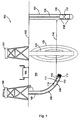
- Fig. 1 shows an example drilling system 100, incorporating an additional borehole for ranging measurements in addition to one relief well and one target well, according to aspects of the present disclosure.
- the drilling system 100 includes rigs 101 and 190 mounted at the surface 103 and positioned above boreholes 102 and 106, respectively, within a subterranean formation 104.
- An additional borehole 107 may also be within the subterranean formation 104.
- the borehole 106 may be in the process of being drilled and may comprise a relief well that is intended to intersect a target well, as will be described below.
- Rig 190 may be coupled to a drilling assembly 150, comprising drill string 108 and bottom hole assembly (BHA) 109.
- BHA bottom hole assembly
- the BHA 109 may comprise a drill bit 110 and a MWD apparatus 112.
- at least one electrode 113 and at least one antenna 111 may be coupled to the BHA 109.
- the at least one electrode 113 may inject or receive current 115 into the formation, and the at least one antenna 111 may measure an EM field 120 within the formation 104 that is induced by the current 115.
- the induced EM field 120 may indicate the location of the borehole 102.
- the position of the at least one electrode 113 and the at least one antenna 111 may be moved to various locations along the drilling assembly. Additionally, in certain embodiments, one or both of the electrodes 113 and antenna 111 may be omitted from the drilling assembly 150.
- the borehole 102 may comprise a target well that has been either totally or partially drilled on a previous occasion by rig 101 and a drilling assembly similar to drilling assembly 109.
- the borehole 102 may be uncased, partially cased, or totally cased.
- the borehole 102 may be a completed well that was at one time producing but has since suffered catastrophic failure, such as a blowout.
- borehole 102 may need to be intersected by drilling assembly 109 and borehole 106 so that pressure within the borehole 102 may be reduced.
- identifying the precise location of the target well 102 may be difficult. But the precise location of the target well may need to be known so that a drilling parameter of the drilling assembly 109, such as a drilling trajectory of the drilling assembly 109, can be selected or altered to intersect the target well 102.
- an additional borehole 107 may be used as part of the ranging measurements to increase the accuracy of formation measurements.
- borehole 107 may comprise a borehole that was previously drilled for survey purposes, or may be a producing well within the formation 104.
- the additional borehole may also be a second relief well being drilled to intersect the target well.
- a downhole wireline tool 116 is disposed in the borehole 107 via a wireline 119.
- the downhole tool 116 comprises at least one electrode 118 and at least one antenna 117.
- the at least one electrode 118 may inject alternating current (AC) 115 into or receive AC 115 from formation 104, and the at least one antenna 117 may measure an EM field 120 that is induced in formation 104 by the current 115.
- the induced EM field 120 may indicate the location of the borehole 102.
- AC may also be injected into or received from formation 104 at an electrode (not shown) disposed within the target well 102. This may increase the visibility of the target well 102.
- the configuration of the downhole tool 116 may be altered including the placement of the at least one electrode 118 and the at least one antenna 117, or the omission of either.
- the downhole tool 116 and the drilling assembly 150 may be in communication with a control unit 105 at the surface.
- the downhole tool 116 may communicate with the surface via wireline 119, and data received at the surface may be communicated to the control unit 105 directly or through a wireless transmission system.
- the drilling assembly 150 and in particular BHA 109, may communicate with the surface via a telemetry system.
- the control unit 105 may comprise an information handling system with a processor and a memory device coupled to the processor.
- the memory device may contain instructions that cause the processor to send control signals to the BHA 109 and downhole tool 116.
- control unit 105 may cause one of the at least one electrodes on the BHA 109 or the downhole tool 116 to inject current into the formation, cause at least one of the electrodes on the other one of the BHA 109 and downhole tool 116 to receive the current, and cause one of the at least one antenna on the BHA 109 or downhole tool 116 to measure the EM field 120.
- the measurements may then be received at the control unit 105, which may process the measurements and alter a drilling parameter of the drilling assembly 150 based on the processed measurements.
- Fig. 2 shows another example drilling system 200, incorporating an additional borehole for ranging measurements beyond one relief well and one target well, according to aspects of the present disclosure.
- the drilling system 200 includes rigs 201, 290, and 230 mounted at the surface 203 and positioned above boreholes 202, 206, and 207, respectively, within a subterranean formation 204.
- borehole 207 may be in the process of being drilled, like borehole 206, and both may comprise relief wells that are intended to intersect target well/borehole 202.
- Rigs 290 and 230 may be coupled to a drilling assemblies 250 and 219, respectively, with the drilling assemblies 250 and 219 respectively comprising drill strings 208 and 275, and BHAs 209 and 260.
- the BHAs 209 and 260 may respectively comprise drill bits 210 and 265, and MWD apparatuses 212 and 270.
- at least one electrode 213 and 218 and at least one antenna 211 and 217 may be coupled to the BHAs 209 and 260, respectively.
- at least one electrode of one BHA 209 and 260 may inject current 215 into the formation, and the other may receive current 215.
- antennas 211 and 217 may measure an EM field 220 within the formation 204.
- the EM field 220 may be excited within the formation 204 and around borehole 202. By measuring the EM field 220, the drilling systems 100 and 200 may identify a location of the target well/borehole 202.
- the positions of the electrodes 213 and 218 in Fig. 2 are not meant to be limiting.
- one or both of the electrodes and antenna may be omitted from the drilling assemblies.
- the number and positions of boreholes in the formations 104 and 204 are not intended to be limiting.
- additional boreholes may be used to effectuate the ranging measurement process. For example, instead of injecting current into the formation or receiving current from the formation at a drilling assembly in a relief well, a fourth borehole with a downhole tool similar to downhole tool 116 may be used to inject current into the formation.
- the drilling assembly need not inject current or receive current, meaning that the drilling assembly need only measure the EM field from the formation. This may increase the accuracy of the measurements, as the measurements would not receive interference from the injected or received current at the drilling assembly.
- a method for obtaining ranging measurements is also described herein.
- the method may be utilized in systems 100 and 200 and those similar to them.
- the method may include injecting a current into a formation from a first borehole.
- the current may be injected from electrodes disposed in the borehole, or, in certain embodiments, by energizing a casing disposed in the borehole.
- the method may further comprise receiving the current from the formation at a second borehole.
- the current may be received, for example, through electrodes disposed in the borehole, or another current return structure that would be well known in the art in view of this disclosure.
- the method may include measuring the induced EM field, using, for example, at least one antenna disposed in one of the first borehole and the second borehole.
- the current 115 may be injected into formation 104 from the at least one electrode 113 in the drilling assembly 150, and may be received at the at least one electrode 118 in the downhole tool 116. In another embodiment, the current 115 may be injected into formation 104 from the at least one electrode 118 in the downhole tool 116, and may be received in at least one electrode 113 in the drilling assembly 150. In either embodiment, the induced EM field 120 may be measured by the at least one antenna 111 disposed in the borehole 106 or the at least one antenna 117 disposed in the borehole 107.
- the current 215 may be injected into formation 204 from at least one electrode 213 in the drilling assembly 250, and may be received at the at least one electrode 218 in the drilling assembly 219.
- the current 215 may be injected into formation 204 from the at least one electrode 218 in the drilling assembly 219, and may be received at least one electrode 213 in the drilling assembly 250.
- the induced EM field 220 may be measured by the at least one antenna 213 disposed in the borehole 206 or the at least one antenna 217 disposed in the borehole 207.
- the current injection and reception may be accomplished in boreholes separate from a relief well and a target well. In such instances, the measurement may take place at an antenna disposed on a drilling assembly in a relief well, with the injection and reception of the current taking place at two boreholes separate from the target and relief wells.
- the method may further include identifying the location of a third borehole within the formation based, at least in part, on the measured EM field.
- the third borehole may comprise a target well.
- the current injected into a formation may induce an EM field within the formation.
- the induced EM field may identify variations in the formation, including the location of the target well.
- the EM field may be transmitted to a control unit, where the location of the target well may be determined.
- the measured EM field may be compared to or incorporated into a formation model that was generated using previously acquired formation survey data.
- the location of the third borehole may be identified, for example, using the comparison of the updated formation model.
- identifying the location of a third borehole within the formation based, at least in part, on the measured EM field may include identifying the location of the third borehole with respect to at least one of the first borehole and the second borehole.
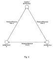
- a direction and distance may be identified between a first borehole A, a second borehole B, and a target borehole.
- the location of the target borehole may be identified by ranging the target borehole from the first borehole A or the second borehole B.
- the location of the target borehole may be identified by triangulating the position of the target borehole using its direction and distance to both the first borehole A and the second borehole B.
- the location of the target borehole may be identified by determining the distance between a first borehole A and a second borehole B, determining the direction from each of the boreholes to the target well, and using trigonometric relations to identify the position of the target well.
- the first borehole A and second borehole B may include relief wells, survey wells, or other wells as described above. Additionally, the first borehole A or second borehole B may be existing production wells, or another formation feature, with a location that is well known. In such instances, the location of the target borehole may be identified with respect to the known location.
- the method may also include altering a drilling parameter of a drilling assembly positioned within the formation based on the location of the third borehole.
- the third borehole may comprise a target well that needs to be intersected by a relief well.
- the relief well may be in the process of being drilled and may include a drilling assembly disposed therein.
- Example relief wells are boreholes 106, 206, and 207 described above.
- the current position and trajectory of the drilling assembly or BHA may be identified using the measured EM field, the formation model described above, or other measurement equipment incorporated into the drilling assembly/BHA.
- the current position and trajectory of the BHA may be communicated to a control unit, along with the measurement of the induced EM field.
- the control unit may adjust a drilling parameter, such as the trajectory of the drilling assembly, according to the above data so that the relief well is pointed towards the target well.
- a drilling parameter such as the trajectory of the drilling assembly
Claims (15)
- Procédé pour obtenir des mesures de télémétrie, comprenant :l'injection d'un courant (115) dans une formation (104) à partir d'un premier trou de forage (106) pour induire un champ électromagnétique (120) dans la formation ;la réception du courant en provenance de la formation au niveau d'un deuxième trou de forage (107) ;la mesure du champ électromagnétique avec au moins une antenne (117) située dans au moins un parmi le premier trou de forage et le deuxième trou de forage ;l'identification de l'emplacement d'un troisième trou de forage (102) à l'intérieur de la formation sur la base, au moins en partie, du champ électromagnétique mesuré ; etsur la base de l'emplacement identifié du troisième trou de forage (102), la modification d'un paramètre de forage d'un ensemble de forage (150) positionné à l'intérieur de la formation en dehors du troisième trou de forage, dans lequel le paramètre de forage est modifié.
- Procédé selon la revendication 1, dans lequel :l'ensemble de forage (150) est disposé dans le premier trou de forage (106) ;le premier trou de forage comprend un puits d'intervention ; etle troisième trou de forage comprend un puits cible.
- Procédé selon la revendication 2, comprenant en outre :l'introduction d'au moins une antenne (117) et d'au moins une électrode (118) dans le deuxième trou de forage (107) ;la réception du courant au niveau de la au moins une électrode ; etla mesure du champ électromagnétique avec la au moins une antenne.
- Procédé selon la revendication 1, dans lequel :l'ensemble de forage est disposé dans le deuxième trou de forage ;le deuxième trou de forage comprend un puits d'intervention ; etle troisième trou de forage comprend un puits cible,et dans lequel, éventuellement, le procédé comprend en outre :l'introduction d'au moins une antenne et d'au moins une électrode dans le premier trou de forage ;l'injection du courant avec la au moins une électrode ; etla mesure du champ électromagnétique avec la au moins une antenne.
- Procédé selon les revendications 2 ou 4, dans lequel l'ensemble de forage comprend les au moins une électrode et au moins une antenne, et dans lequel le champ électromagnétique est mesuré à l'aide de la au moins une antenne.
- Procédé selon la revendication 1, dans lequel :l'ensemble de forage (250) est disposé dans le premier trou de forage (206) ;un second ensemble de forage (219) est disposé dans le deuxième trou de forage (207);les premier et deuxième trous de forage comprennent respectivement des premier et second puits d'intervention ; etle troisième trou de forage (202) comprend un puits cible.
- Procédé selon la revendication 6, comprenant en outre :la modification d'un paramètre de forage du second ensemble de forage (219) sur la base de l'emplacement du troisième trou de forage (202).
- Procédé selon la revendication 1, comprenant en outre une parmi :l'injection d'un second courant dans une formation à partir du troisième trou de forage ; etla réception du courant en provenance de la formation au niveau du troisième trou de forage ;dans lequel le troisième trou de forage comprend un puits cible.
- Procédé selon la revendication 1, dans lequel l'étape d'identification de l'emplacement d'un troisième trou de forage à l'intérieur de la formation sur la base, au moins en partie, du champ électromagnétique mesuré comprend :l'identification de l'emplacement du troisième trou de forage par rapport à au moins un parmi le premier trou de forage et le deuxième trou de forage.
- Procédé selon l'une quelconque des revendications précédentes, dans lequel le paramètre de forage comprend une trajectoire de l'ensemble de forage.
- Système pour obtenir des mesures de télémétrie, comprenant :une première électrode (113) destinée à être disposée à l'intérieur d'un premier trou de forage (106) dans une formation (104) ;une deuxième électrode (118) destinée à être disposée à l'intérieur d'un deuxième trou de forage (107) dans la formation ;au moins une antenne (111) destinée à être disposée à l'intérieur d'au moins un parmi le premier trou de forage et le deuxième trou de forage ;une unité de commande (105) en communication avec la première électrode, la deuxième électrode, et la au moins une antenne, dans lequel l'unité de commande est agencée pour :amener la première électrode à injecter un courant dans la formation ;amener la deuxième électrode à recevoir le courant en provenance de la formation ;amener la au moins une antenne à mesurer un champ électromagnétique induit par le courant ;identifier l'emplacement d'un troisième trou de forage (102) à l'intérieur de la formation sur la base, au moins en partie, du champ électromagnétique mesuré; etmodifier un paramètre de forage d'un ensemble de forage (150) positionné à l'intérieur de la formation en dehors du troisième trou de forage, dans lequel le paramètre de forage est modifié sur la base de l'emplacement du troisième trou de forage.
- Système selon la revendication 11, dans lequel :l'ensemble de forage (150) est disposé dans le premier trou de forage ;le premier trou de forage comprend un puits d'intervention ; etle troisième trou de forage comprend un puits cible,et éventuellement dans lequel le système comprend en outre un outil de fond de trou (116) destiné à être disposé dans le deuxième trou de forage, dans lequel la deuxième électrode (118) et la au moins une antenne (111) sont couplées à l'outil de fond de trou.
- Système selon la revendication 11, dans lequel :l'ensemble de forage est disposé dans le deuxième trou de forage ;le deuxième trou de forage comprend un puits d'intervention ; etle troisième trou de forage comprend un puits cible,et éventuellement dans lequel le système comprend en outre un outil de fond de trou destiné à être disposé dans le premier trou de forage, dans lequel la première électrode et la au moins une antenne sont couplées à l'outil de fond de trou.
- Système selon les revendications 12 ou 13, comprenant en outre une troisième électrode destinée à être disposée dans le troisième trou de forage, dans lequel l'unité de commande est agencée pour amener la troisième électrode à injecter un second courant dans la formation ou à recevoir le courant en provenance de la formation.
- Système selon la revendication 11, dans lequel :l'ensemble de forage (250) doit être disposé dans le premier trou de forage ;un second ensemble de forage du système doit être disposé dans le deuxième trou de forage ;les premier et deuxième trous de forage comprennent respectivement des premier et second puits d'intervention ; etle troisième trou de forage comprend un puits cible.
Priority Applications (1)
| Application Number | Priority Date | Filing Date | Title |
|---|---|---|---|
| EP16178993.8A EP3115548B1 (fr) | 2012-12-21 | 2012-12-21 | Systèmes et procédés permettant d'effectuer des mesures de télémétrie au moyen d'un troisième puits de référencement |
Applications Claiming Priority (1)
| Application Number | Priority Date | Filing Date | Title |
|---|---|---|---|
| PCT/US2012/071226 WO2014098891A1 (fr) | 2012-12-21 | 2012-12-21 | Systèmes et procédés permettant d'effectuer des mesures de télémétrie à l'aide du référencement d'un troisième puits |
Related Child Applications (2)
| Application Number | Title | Priority Date | Filing Date |
|---|---|---|---|
| EP16178993.8A Division EP3115548B1 (fr) | 2012-12-21 | 2012-12-21 | Systèmes et procédés permettant d'effectuer des mesures de télémétrie au moyen d'un troisième puits de référencement |
| EP16178993.8A Division-Into EP3115548B1 (fr) | 2012-12-21 | 2012-12-21 | Systèmes et procédés permettant d'effectuer des mesures de télémétrie au moyen d'un troisième puits de référencement |
Publications (2)
| Publication Number | Publication Date |
|---|---|
| EP2935779A1 EP2935779A1 (fr) | 2015-10-28 |
| EP2935779B1 true EP2935779B1 (fr) | 2016-10-12 |
Family
ID=47628429
Family Applications (2)
| Application Number | Title | Priority Date | Filing Date |
|---|---|---|---|
| EP16178993.8A Active EP3115548B1 (fr) | 2012-12-21 | 2012-12-21 | Systèmes et procédés permettant d'effectuer des mesures de télémétrie au moyen d'un troisième puits de référencement |
| EP12819163.2A Active EP2935779B1 (fr) | 2012-12-21 | 2012-12-21 | Systèmes et procédés permettant d'effectuer des mesures de télémétrie à l'aide du référencement d'un troisième puits |
Family Applications Before (1)
| Application Number | Title | Priority Date | Filing Date |
|---|---|---|---|
| EP16178993.8A Active EP3115548B1 (fr) | 2012-12-21 | 2012-12-21 | Systèmes et procédés permettant d'effectuer des mesures de télémétrie au moyen d'un troisième puits de référencement |
Country Status (9)
| Country | Link |
|---|---|
| US (1) | US9625605B2 (fr) |
| EP (2) | EP3115548B1 (fr) |
| CN (1) | CN104919136B (fr) |
| AU (1) | AU2012397234B2 (fr) |
| BR (1) | BR112015011490B1 (fr) |
| CA (1) | CA2892072C (fr) |
| MY (1) | MY185714A (fr) |
| RU (1) | RU2619952C2 (fr) |
| WO (1) | WO2014098891A1 (fr) |
Families Citing this family (13)
| Publication number | Priority date | Publication date | Assignee | Title |
|---|---|---|---|---|
| US10760406B2 (en) | 2014-12-30 | 2020-09-01 | Halliburton Energy Services, Inc. | Locating multiple wellbores |
| US11151762B2 (en) | 2015-11-03 | 2021-10-19 | Ubiterra Corporation | Systems and methods for shared visualization and display of drilling information |
| US20170122095A1 (en) * | 2015-11-03 | 2017-05-04 | Ubiterra Corporation | Automated geo-target and geo-hazard notifications for drilling systems |
| US10844705B2 (en) | 2016-01-20 | 2020-11-24 | Halliburton Energy Services, Inc. | Surface excited downhole ranging using relative positioning |
| DE102016002479A1 (de) * | 2016-03-03 | 2017-09-07 | Tracto-Technik Gmbh & Co. Kg | Verfahren zum Einbringen einer Bohrung in das Erdreich und Erdbohrvorrichtung sowie Verwendung |
| WO2018056999A1 (fr) | 2016-09-23 | 2018-03-29 | Halliburton Energy Services, Inc. | Utilisation de diverses sources d'excitation dans une télémétrie électromagnétique |
| WO2018063162A1 (fr) | 2016-09-27 | 2018-04-05 | Halliburton Energy Services, Inc. | Étalonnage d'outils de télémétrie électromagnétique |
| EP3485139A4 (fr) | 2016-10-20 | 2020-03-25 | Halliburton Energy Services, Inc. | Mesures de télémétrie dans un puits de forage non linéaire |
| CA3046919C (fr) | 2017-01-31 | 2023-03-07 | Halliburton Energy Services, Inc. | Optimisation de mesures de telemetrie |
| WO2018222199A1 (fr) | 2017-06-01 | 2018-12-06 | Halliburton Energy Services, Inc. | Télémétrie magnétique active entre puits tubés |
| WO2019083762A1 (fr) | 2017-10-26 | 2019-05-02 | Halliburton Energy Services, Inc. | Détermination de propriétés de tubage et de formation à l'aide de mesures électromagnétiques |
| EP3833850B1 (fr) * | 2018-11-30 | 2023-07-05 | Halliburton Energy Services Inc. | Procédé d'excitation de surfaces multiples pour déterminer un emplacement d'opérations de forage sur des puits existants |
| CN117090558A (zh) * | 2023-08-16 | 2023-11-21 | 中国石油天然气集团有限公司 | 救援井轨迹调整方法及装置 |
Family Cites Families (21)
| Publication number | Priority date | Publication date | Assignee | Title |
|---|---|---|---|---|
| US4372398A (en) * | 1980-11-04 | 1983-02-08 | Cornell Research Foundation, Inc. | Method of determining the location of a deep-well casing by magnetic field sensing |
| EP0104854A3 (fr) * | 1982-09-28 | 1985-04-10 | Mobil Oil Corporation | Procédé de magnétisation de la paroi d'un puits |
| US4593770A (en) | 1984-11-06 | 1986-06-10 | Mobil Oil Corporation | Method for preventing the drilling of a new well into one of a plurality of production wells |
| GB8613027D0 (en) * | 1986-05-29 | 1986-07-02 | Shell Int Research | Determining distance between adjacent wells |
| US5074365A (en) * | 1990-09-14 | 1991-12-24 | Vector Magnetics, Inc. | Borehole guidance system having target wireline |
| US5485089A (en) * | 1992-11-06 | 1996-01-16 | Vector Magnetics, Inc. | Method and apparatus for measuring distance and direction by movable magnetic field source |
| US20090120691A1 (en) * | 2004-11-30 | 2009-05-14 | General Electric Company | Systems and methods for guiding the drilling of a horizontal well |
| US7475741B2 (en) * | 2004-11-30 | 2009-01-13 | General Electric Company | Method and system for precise drilling guidance of twin wells |
| US7495446B2 (en) * | 2005-08-23 | 2009-02-24 | Schlumberger Technology Corporation | Formation evaluation system and method |
| US7703548B2 (en) | 2006-08-16 | 2010-04-27 | Schlumberger Technology Corporation | Magnetic ranging while drilling parallel wells |
| US8113272B2 (en) * | 2007-10-19 | 2012-02-14 | Shell Oil Company | Three-phase heaters with common overburden sections for heating subsurface formations |
| US8827005B2 (en) * | 2008-04-17 | 2014-09-09 | Schlumberger Technology Corporation | Method for drilling wells in close relationship using magnetic ranging while drilling |
| US8596382B2 (en) | 2008-04-18 | 2013-12-03 | Schlumbeger Technology Corporation | Magnetic ranging while drilling using an electric dipole source and a magnetic field sensor |
| WO2009142782A2 (fr) * | 2008-05-23 | 2009-11-26 | Schlumberger Canada Limited | Système et procédé de remblayage dense de puits à l’aide de la télémétrie magnétique pendant le forage |
| US8842020B2 (en) | 2008-07-24 | 2014-09-23 | Schlumberger Technology Corporation | System and method for detecting casing in a formation using current |
| WO2010065208A1 (fr) * | 2008-12-02 | 2010-06-10 | Schlumberger Canada Limited | Relevé électromagnétique utilisant des tubages de puits métalliques comme électrodes |
| US8322462B2 (en) * | 2008-12-22 | 2012-12-04 | Halliburton Energy Services, Inc. | Proximity detection system for deep wells |
| US8618803B2 (en) * | 2009-06-17 | 2013-12-31 | Halliburton Energy Services, Inc. | Well location determination apparatus, methods, and systems |
| EP2317069A1 (fr) * | 2009-10-30 | 2011-05-04 | Welltec A/S | Système de télémetrie par magnétisme pour contrôler un procès de forage |
| CN101713287B (zh) * | 2009-11-04 | 2012-10-24 | 中国石油大学(北京) | 一种用于邻井距离随钻电磁探测的磁短节 |
| CN101806210B (zh) * | 2010-04-13 | 2014-01-01 | 中国石油大学(北京) | 一种螺线管组随钻电磁测距导向系统 |
-
2012
- 2012-12-21 US US14/650,238 patent/US9625605B2/en active Active
- 2012-12-21 RU RU2015119252A patent/RU2619952C2/ru not_active IP Right Cessation
- 2012-12-21 EP EP16178993.8A patent/EP3115548B1/fr active Active
- 2012-12-21 CA CA2892072A patent/CA2892072C/fr active Active
- 2012-12-21 BR BR112015011490-3A patent/BR112015011490B1/pt active IP Right Grant
- 2012-12-21 MY MYPI2015701576A patent/MY185714A/en unknown
- 2012-12-21 EP EP12819163.2A patent/EP2935779B1/fr active Active
- 2012-12-21 WO PCT/US2012/071226 patent/WO2014098891A1/fr active Application Filing
- 2012-12-21 AU AU2012397234A patent/AU2012397234B2/en not_active Ceased
- 2012-12-21 CN CN201280077209.7A patent/CN104919136B/zh not_active Expired - Fee Related
Also Published As
| Publication number | Publication date |
|---|---|
| RU2015119252A (ru) | 2017-01-30 |
| AU2012397234A1 (en) | 2015-05-21 |
| AU2012397234B2 (en) | 2016-05-19 |
| CN104919136B (zh) | 2018-07-10 |
| US9625605B2 (en) | 2017-04-18 |
| EP2935779A1 (fr) | 2015-10-28 |
| CN104919136A (zh) | 2015-09-16 |
| US20150331139A1 (en) | 2015-11-19 |
| WO2014098891A1 (fr) | 2014-06-26 |
| EP3115548B1 (fr) | 2018-08-01 |
| BR112015011490A2 (pt) | 2017-07-11 |
| MY185714A (en) | 2021-05-31 |
| RU2619952C2 (ru) | 2017-05-22 |
| CA2892072A1 (fr) | 2014-06-26 |
| EP3115548A1 (fr) | 2017-01-11 |
| CA2892072C (fr) | 2017-07-04 |
| BR112015011490B1 (pt) | 2021-07-20 |
Similar Documents
| Publication | Publication Date | Title |
|---|---|---|
| EP2935779B1 (fr) | Systèmes et procédés permettant d'effectuer des mesures de télémétrie à l'aide du référencement d'un troisième puits | |
| AU2016247116B2 (en) | Self-guided geosteering assembly and method for optimizing well placement and quality | |
| EP2926174B1 (fr) | Systèmes et procédés permettant de mesurer une résistivité vers l'avant avec des informations de puits de limite | |
| EP2936213B1 (fr) | Méthode et appareil d'optimisation de mesures de résistivité en profondeur avec des antennes à composants multiples | |
| US10443371B2 (en) | Directional button excitation for ranging applications | |
| US20140216734A1 (en) | Casing collar location using elecromagnetic wave phase shift measurement | |
| US10508534B2 (en) | Planning and real time optimization of electrode transmitter excitation | |
| US9157317B2 (en) | Combination power source for a magnetic ranging system | |
| Nekut et al. | Rotating magnet ranging-a new drilling guidance technology | |
| US10465496B2 (en) | Sleeve excitation for ranging measurements using electrode sources | |
| CA3004887C (fr) | Procedes et systemes utilisant un agencement de capteurs de gradient pour telemetrie | |
| CA3180585A1 (fr) | Telemetrie magnetique active par injection de courant de tete de puits | |
| US11680479B2 (en) | Multiple surface excitation method for determining a location of drilling operations to existing wells |
Legal Events
| Date | Code | Title | Description |
|---|---|---|---|
| PUAI | Public reference made under article 153(3) epc to a published international application that has entered the european phase |
Free format text: ORIGINAL CODE: 0009012 |
|
| 17P | Request for examination filed |
Effective date: 20150520 |
|
| AK | Designated contracting states |
Kind code of ref document: A1 Designated state(s): AL AT BE BG CH CY CZ DE DK EE ES FI FR GB GR HR HU IE IS IT LI LT LU LV MC MK MT NL NO PL PT RO RS SE SI SK SM TR |
|
| AX | Request for extension of the european patent |
Extension state: BA ME |
|
| RIN1 | Information on inventor provided before grant (corrected) |
Inventor name: WU, HSU-HSIANG Inventor name: SIMEONOV, SVETOZAR, DIMITROV Inventor name: DONDERICI, BURKAY Inventor name: SAN MARTIN, LUIS Inventor name: UPSHALL, MALCOLM |
|
| DAX | Request for extension of the european patent (deleted) | ||
| GRAP | Despatch of communication of intention to grant a patent |
Free format text: ORIGINAL CODE: EPIDOSNIGR1 |
|
| INTG | Intention to grant announced |
Effective date: 20160502 |
|
| GRAS | Grant fee paid |
Free format text: ORIGINAL CODE: EPIDOSNIGR3 |
|
| GRAA | (expected) grant |
Free format text: ORIGINAL CODE: 0009210 |
|
| AK | Designated contracting states |
Kind code of ref document: B1 Designated state(s): AL AT BE BG CH CY CZ DE DK EE ES FI FR GB GR HR HU IE IS IT LI LT LU LV MC MK MT NL NO PL PT RO RS SE SI SK SM TR |
|
| REG | Reference to a national code |
Ref country code: GB Ref legal event code: FG4D |
|
| REG | Reference to a national code |
Ref country code: CH Ref legal event code: EP |
|
| REG | Reference to a national code |
Ref country code: AT Ref legal event code: REF Ref document number: 836709 Country of ref document: AT Kind code of ref document: T Effective date: 20161015 |
|
| REG | Reference to a national code |
Ref country code: IE Ref legal event code: FG4D |
|
| REG | Reference to a national code |
Ref country code: DE Ref legal event code: R096 Ref document number: 602012024130 Country of ref document: DE |
|
| REG | Reference to a national code |
Ref country code: NO Ref legal event code: T2 Effective date: 20161012 |
|
| REG | Reference to a national code |
Ref country code: LT Ref legal event code: MG4D |
|
| REG | Reference to a national code |
Ref country code: NL Ref legal event code: MP Effective date: 20161012 |
|
| PG25 | Lapsed in a contracting state [announced via postgrant information from national office to epo] |
Ref country code: LV Free format text: LAPSE BECAUSE OF FAILURE TO SUBMIT A TRANSLATION OF THE DESCRIPTION OR TO PAY THE FEE WITHIN THE PRESCRIBED TIME-LIMIT Effective date: 20161012 |
|
| REG | Reference to a national code |
Ref country code: AT Ref legal event code: MK05 Ref document number: 836709 Country of ref document: AT Kind code of ref document: T Effective date: 20161012 |
|
| PG25 | Lapsed in a contracting state [announced via postgrant information from national office to epo] |
Ref country code: SE Free format text: LAPSE BECAUSE OF FAILURE TO SUBMIT A TRANSLATION OF THE DESCRIPTION OR TO PAY THE FEE WITHIN THE PRESCRIBED TIME-LIMIT Effective date: 20161012 Ref country code: LT Free format text: LAPSE BECAUSE OF FAILURE TO SUBMIT A TRANSLATION OF THE DESCRIPTION OR TO PAY THE FEE WITHIN THE PRESCRIBED TIME-LIMIT Effective date: 20161012 Ref country code: GR Free format text: LAPSE BECAUSE OF FAILURE TO SUBMIT A TRANSLATION OF THE DESCRIPTION OR TO PAY THE FEE WITHIN THE PRESCRIBED TIME-LIMIT Effective date: 20170113 |
|
| PG25 | Lapsed in a contracting state [announced via postgrant information from national office to epo] |
Ref country code: HR Free format text: LAPSE BECAUSE OF FAILURE TO SUBMIT A TRANSLATION OF THE DESCRIPTION OR TO PAY THE FEE WITHIN THE PRESCRIBED TIME-LIMIT Effective date: 20161012 Ref country code: NL Free format text: LAPSE BECAUSE OF FAILURE TO SUBMIT A TRANSLATION OF THE DESCRIPTION OR TO PAY THE FEE WITHIN THE PRESCRIBED TIME-LIMIT Effective date: 20161012 Ref country code: PT Free format text: LAPSE BECAUSE OF FAILURE TO SUBMIT A TRANSLATION OF THE DESCRIPTION OR TO PAY THE FEE WITHIN THE PRESCRIBED TIME-LIMIT Effective date: 20170213 Ref country code: FI Free format text: LAPSE BECAUSE OF FAILURE TO SUBMIT A TRANSLATION OF THE DESCRIPTION OR TO PAY THE FEE WITHIN THE PRESCRIBED TIME-LIMIT Effective date: 20161012 Ref country code: PL Free format text: LAPSE BECAUSE OF FAILURE TO SUBMIT A TRANSLATION OF THE DESCRIPTION OR TO PAY THE FEE WITHIN THE PRESCRIBED TIME-LIMIT Effective date: 20161012 Ref country code: ES Free format text: LAPSE BECAUSE OF FAILURE TO SUBMIT A TRANSLATION OF THE DESCRIPTION OR TO PAY THE FEE WITHIN THE PRESCRIBED TIME-LIMIT Effective date: 20161012 Ref country code: IS Free format text: LAPSE BECAUSE OF FAILURE TO SUBMIT A TRANSLATION OF THE DESCRIPTION OR TO PAY THE FEE WITHIN THE PRESCRIBED TIME-LIMIT Effective date: 20170212 Ref country code: AT Free format text: LAPSE BECAUSE OF FAILURE TO SUBMIT A TRANSLATION OF THE DESCRIPTION OR TO PAY THE FEE WITHIN THE PRESCRIBED TIME-LIMIT Effective date: 20161012 Ref country code: RS Free format text: LAPSE BECAUSE OF FAILURE TO SUBMIT A TRANSLATION OF THE DESCRIPTION OR TO PAY THE FEE WITHIN THE PRESCRIBED TIME-LIMIT Effective date: 20161012 Ref country code: BE Free format text: LAPSE BECAUSE OF FAILURE TO SUBMIT A TRANSLATION OF THE DESCRIPTION OR TO PAY THE FEE WITHIN THE PRESCRIBED TIME-LIMIT Effective date: 20161012 |
|
| REG | Reference to a national code |
Ref country code: DE Ref legal event code: R097 Ref document number: 602012024130 Country of ref document: DE |
|
| PG25 | Lapsed in a contracting state [announced via postgrant information from national office to epo] |
Ref country code: EE Free format text: LAPSE BECAUSE OF FAILURE TO SUBMIT A TRANSLATION OF THE DESCRIPTION OR TO PAY THE FEE WITHIN THE PRESCRIBED TIME-LIMIT Effective date: 20161012 Ref country code: CZ Free format text: LAPSE BECAUSE OF FAILURE TO SUBMIT A TRANSLATION OF THE DESCRIPTION OR TO PAY THE FEE WITHIN THE PRESCRIBED TIME-LIMIT Effective date: 20161012 Ref country code: DK Free format text: LAPSE BECAUSE OF FAILURE TO SUBMIT A TRANSLATION OF THE DESCRIPTION OR TO PAY THE FEE WITHIN THE PRESCRIBED TIME-LIMIT Effective date: 20161012 Ref country code: SK Free format text: LAPSE BECAUSE OF FAILURE TO SUBMIT A TRANSLATION OF THE DESCRIPTION OR TO PAY THE FEE WITHIN THE PRESCRIBED TIME-LIMIT Effective date: 20161012 Ref country code: RO Free format text: LAPSE BECAUSE OF FAILURE TO SUBMIT A TRANSLATION OF THE DESCRIPTION OR TO PAY THE FEE WITHIN THE PRESCRIBED TIME-LIMIT Effective date: 20161012 |
|
| REG | Reference to a national code |
Ref country code: CH Ref legal event code: PL |
|
| PLBE | No opposition filed within time limit |
Free format text: ORIGINAL CODE: 0009261 |
|
| STAA | Information on the status of an ep patent application or granted ep patent |
Free format text: STATUS: NO OPPOSITION FILED WITHIN TIME LIMIT |
|
| PG25 | Lapsed in a contracting state [announced via postgrant information from national office to epo] |
Ref country code: SM Free format text: LAPSE BECAUSE OF FAILURE TO SUBMIT A TRANSLATION OF THE DESCRIPTION OR TO PAY THE FEE WITHIN THE PRESCRIBED TIME-LIMIT Effective date: 20161012 Ref country code: BG Free format text: LAPSE BECAUSE OF FAILURE TO SUBMIT A TRANSLATION OF THE DESCRIPTION OR TO PAY THE FEE WITHIN THE PRESCRIBED TIME-LIMIT Effective date: 20170112 Ref country code: IT Free format text: LAPSE BECAUSE OF FAILURE TO SUBMIT A TRANSLATION OF THE DESCRIPTION OR TO PAY THE FEE WITHIN THE PRESCRIBED TIME-LIMIT Effective date: 20161012 |
|
| 26N | No opposition filed |
Effective date: 20170713 |
|
| PG25 | Lapsed in a contracting state [announced via postgrant information from national office to epo] |
Ref country code: MC Free format text: LAPSE BECAUSE OF FAILURE TO SUBMIT A TRANSLATION OF THE DESCRIPTION OR TO PAY THE FEE WITHIN THE PRESCRIBED TIME-LIMIT Effective date: 20161012 |
|
| REG | Reference to a national code |
Ref country code: FR Ref legal event code: ST Effective date: 20170831 |
|
| REG | Reference to a national code |
Ref country code: IE Ref legal event code: MM4A |
|
| PG25 | Lapsed in a contracting state [announced via postgrant information from national office to epo] |
Ref country code: LI Free format text: LAPSE BECAUSE OF NON-PAYMENT OF DUE FEES Effective date: 20161231 Ref country code: FR Free format text: LAPSE BECAUSE OF NON-PAYMENT OF DUE FEES Effective date: 20170102 Ref country code: LU Free format text: LAPSE BECAUSE OF NON-PAYMENT OF DUE FEES Effective date: 20161221 Ref country code: CH Free format text: LAPSE BECAUSE OF NON-PAYMENT OF DUE FEES Effective date: 20161231 |
|
| PG25 | Lapsed in a contracting state [announced via postgrant information from national office to epo] |
Ref country code: IE Free format text: LAPSE BECAUSE OF NON-PAYMENT OF DUE FEES Effective date: 20161221 Ref country code: SI Free format text: LAPSE BECAUSE OF FAILURE TO SUBMIT A TRANSLATION OF THE DESCRIPTION OR TO PAY THE FEE WITHIN THE PRESCRIBED TIME-LIMIT Effective date: 20161012 |
|
| PG25 | Lapsed in a contracting state [announced via postgrant information from national office to epo] |
Ref country code: HU Free format text: LAPSE BECAUSE OF FAILURE TO SUBMIT A TRANSLATION OF THE DESCRIPTION OR TO PAY THE FEE WITHIN THE PRESCRIBED TIME-LIMIT; INVALID AB INITIO Effective date: 20121221 |
|
| PG25 | Lapsed in a contracting state [announced via postgrant information from national office to epo] |
Ref country code: CY Free format text: LAPSE BECAUSE OF FAILURE TO SUBMIT A TRANSLATION OF THE DESCRIPTION OR TO PAY THE FEE WITHIN THE PRESCRIBED TIME-LIMIT Effective date: 20161012 Ref country code: MK Free format text: LAPSE BECAUSE OF FAILURE TO SUBMIT A TRANSLATION OF THE DESCRIPTION OR TO PAY THE FEE WITHIN THE PRESCRIBED TIME-LIMIT Effective date: 20161012 |
|
| PG25 | Lapsed in a contracting state [announced via postgrant information from national office to epo] |
Ref country code: MT Free format text: LAPSE BECAUSE OF NON-PAYMENT OF DUE FEES Effective date: 20161221 |
|
| PG25 | Lapsed in a contracting state [announced via postgrant information from national office to epo] |
Ref country code: TR Free format text: LAPSE BECAUSE OF FAILURE TO SUBMIT A TRANSLATION OF THE DESCRIPTION OR TO PAY THE FEE WITHIN THE PRESCRIBED TIME-LIMIT Effective date: 20161012 |
|
| PGFP | Annual fee paid to national office [announced via postgrant information from national office to epo] |
Ref country code: DE Payment date: 20191230 Year of fee payment: 8 |
|
| PG25 | Lapsed in a contracting state [announced via postgrant information from national office to epo] |
Ref country code: AL Free format text: LAPSE BECAUSE OF FAILURE TO SUBMIT A TRANSLATION OF THE DESCRIPTION OR TO PAY THE FEE WITHIN THE PRESCRIBED TIME-LIMIT Effective date: 20161012 |
|
| REG | Reference to a national code |
Ref country code: DE Ref legal event code: R119 Ref document number: 602012024130 Country of ref document: DE |
|
| PG25 | Lapsed in a contracting state [announced via postgrant information from national office to epo] |
Ref country code: DE Free format text: LAPSE BECAUSE OF NON-PAYMENT OF DUE FEES Effective date: 20210701 |
|
| PGFP | Annual fee paid to national office [announced via postgrant information from national office to epo] |
Ref country code: GB Payment date: 20231106 Year of fee payment: 12 |
|
| PGFP | Annual fee paid to national office [announced via postgrant information from national office to epo] |
Ref country code: NO Payment date: 20231123 Year of fee payment: 12 |