EP2935072B1 - Stair lift drive system for a smooth dented rail - Google Patents
Stair lift drive system for a smooth dented rail Download PDFInfo
- Publication number
- EP2935072B1 EP2935072B1 EP13818482.5A EP13818482A EP2935072B1 EP 2935072 B1 EP2935072 B1 EP 2935072B1 EP 13818482 A EP13818482 A EP 13818482A EP 2935072 B1 EP2935072 B1 EP 2935072B1
- Authority
- EP
- European Patent Office
- Prior art keywords
- rail
- wheels
- stair lift
- drive system
- recess
- Prior art date
- Legal status (The legal status is an assumption and is not a legal conclusion. Google has not performed a legal analysis and makes no representation as to the accuracy of the status listed.)
- Active
Links
Images




Classifications
-
- B—PERFORMING OPERATIONS; TRANSPORTING
- B66—HOISTING; LIFTING; HAULING
- B66B—ELEVATORS; ESCALATORS OR MOVING WALKWAYS
- B66B9/00—Kinds or types of lifts in, or associated with, buildings or other structures
- B66B9/06—Kinds or types of lifts in, or associated with, buildings or other structures inclined, e.g. serving blast furnaces
- B66B9/08—Kinds or types of lifts in, or associated with, buildings or other structures inclined, e.g. serving blast furnaces associated with stairways, e.g. for transporting disabled persons
- B66B9/0807—Driving mechanisms
-
- B—PERFORMING OPERATIONS; TRANSPORTING
- B66—HOISTING; LIFTING; HAULING
- B66B—ELEVATORS; ESCALATORS OR MOVING WALKWAYS
- B66B9/00—Kinds or types of lifts in, or associated with, buildings or other structures
- B66B9/06—Kinds or types of lifts in, or associated with, buildings or other structures inclined, e.g. serving blast furnaces
- B66B9/08—Kinds or types of lifts in, or associated with, buildings or other structures inclined, e.g. serving blast furnaces associated with stairways, e.g. for transporting disabled persons
- B66B9/0807—Driving mechanisms
- B66B9/0815—Rack and pinion, friction rollers
-
- B—PERFORMING OPERATIONS; TRANSPORTING
- B66—HOISTING; LIFTING; HAULING
- B66B—ELEVATORS; ESCALATORS OR MOVING WALKWAYS
- B66B9/00—Kinds or types of lifts in, or associated with, buildings or other structures
- B66B9/06—Kinds or types of lifts in, or associated with, buildings or other structures inclined, e.g. serving blast furnaces
- B66B9/08—Kinds or types of lifts in, or associated with, buildings or other structures inclined, e.g. serving blast furnaces associated with stairways, e.g. for transporting disabled persons
- B66B9/0846—Guide rail
-
- B—PERFORMING OPERATIONS; TRANSPORTING
- B66—HOISTING; LIFTING; HAULING
- B66B—ELEVATORS; ESCALATORS OR MOVING WALKWAYS
- B66B9/00—Kinds or types of lifts in, or associated with, buildings or other structures
- B66B9/06—Kinds or types of lifts in, or associated with, buildings or other structures inclined, e.g. serving blast furnaces
- B66B9/08—Kinds or types of lifts in, or associated with, buildings or other structures inclined, e.g. serving blast furnaces associated with stairways, e.g. for transporting disabled persons
Definitions
- the present invention relates to a stair lift drive.
- the invention relates to a stair lift for use in combination with a smooth dented rail.
- Stair lifts are known in the art, and the drives applied may have gears, toothed racks, or friction drives.
- EP 2 433 892 A1 discloses a friction drive for a stair lift along a longitudinal guide, wherein multiple rollers are in frictional engagement with a rail.
- the rails used in these drives have teeth or other sharp parts, which form a potential danger to users of the stairs and or stair lift.
- the use of the drive described in this patent is limited to straight / longitudinal guides.
- the invention thereto proposes a stair lift drive, comprising a rail extending along a track, which is at least provided with one dent or recess that extends in a direction tangential to the rail; a frame part, provided with at least one set of wheels, of which at least one wheel engages on the rail in the at least recess, wherein the wheels are each rotatable about an axis which extends substantially perpendicular to the direction from the recess of the rail where the at least one wheel engages to the centreline of the rail as well as perpendicular to a direction tangential to the direction of the rail; a propulsion, to drive at least one of the wheels, wherein the running surfaces of the wheels engage at least a part of the recess in a form-fitting manner, characterised in that the cross section of the rail has a substantially smooth shape.
- each frame part the resultant of the traction forces engages the rail in the so called engagement point.
- the engagement point is substantially coincide with the rotational axes, about which the frame part can rotate with respect to the mounting part.
- the rotational axes cross each other at the engagement point, connecting the driven wheel with the rail.
- the engagement point is substantially coincided with the rotational axes of its frame section.
- the rail will be positioned close to one side of the staircase, wherein the smooth shape of the rail is predominantly focussed on the absence of sharp corners and greasy racks, pointing towards the user of the stair lift.
- a smooth surface may for instance be defined as a surface having no edges with a smaller radius than 15 mm, or than 10 mm, or 5 mm. Therefor, the rail is safe to touch during use, and when the stair lift is idle.
- the smooth rail may be produced by making indentations in a substantially cylindrical tube, and it can be bent and twisted into multiple corners for forming a curved track.
- the rail substantially maintains its original diameter on the section where the rail is not dented, and the overall circumference can therefor remain substantially the same.
- the rail may be designed such that its cross section remains its same angular orientation throughout the track, but still, the drive according to the invention is less vulnerable for torsion occurring during production of the rail, since twisting and turning of the rail can be overcome by other parts of the drive, as will be described below.
- a pair of wheels two wheels pressing on the rail are intended.
- the presence of more wheels or sets of wheels is not excluded.
- the wheels may be located next to each other in the same recess, but can also be located opposite to each other in two opposing recesses, if present in the rail.
- the at least one wheel that engages in the recess of the rail determines the angular orientation of the frame about the axis of the rail. This wheel is not necessarily the driven wheel.
- Two or more recesses or dents provide the advantage that a more stable coupling to the rail is possible, also in a rotational direction about the direction tangential to the rail.
- the number of wheels is also not necessarily limited or equal to the number of recesses in the rail.
- the wheels engage the rail under the influence of friction.
- friction wheels instead of for example toothed wheels allows the wheels to follow the smooth rail, along all its bends, twists and corners, without jamming or collision.
- the running surfaces of the wheels are typically pressed against matching running surfaces of recesses in the rail. Such running surfaces of the wheels can for instance be made out of polyurethane, like Vulkollan, commercially available from Bayer. Because the wheels engage at least part of the recess in a form-fitting manner, the wheels are able to support the drive and compensate for torsion about the direction tangential to the rail.
- the rail has a substantially 8-shaped, apple-core shaped, single or multi-dented-tube shaped or lemniscates shaped cross section.
- This cross section can for instance be realised when a cylinder shaped or oval rail is on two opposing sides provided with recesses that extend over predominantly the whole length of the rail.
- This single or multiple-dented shape can easily be manufactured and can afterwards or at the time of forming the dents be bent into the desired shape to follow the desired contours of a staircase.
- the specifically shaped cross section also offers torsion stiffness and flexural rigidity as well as horizontal and vertical stabilisation and an orientation that prevents rotation of the stair lift around the rail.
- the rail can be formed by means of the method according to the European Patent application EP 11 189 248.5 by the same applicant.
- the part of the recess wherein the substantially straight running surfaces engage the rail comprise an angle between 80 and 135 degrees.
- Each dented area or recess comprises an angle along the circumference of the rail, which may be between 70 and 110, and in particular about 90 degrees for a rail with a single dent, between 60 and 90 degrees and in particular about 75 degrees for a rail with two dents and between 45 and 75 degrees and in particular about 60 degrees for a rail with three dents.
- the dent may comprise substantially straight section(s) to provide a surface to prevent rotation around the longitudinal axes of the rail. Consequently, the part of the wheel that encounters the rail then may have essentially the same shape as the shape of the tube's dent.
- the rail is a monorail, which is advantageous in that it requires less modification of the location where it is to be installed and in that it requires less space.
- the pressure under which the wheels of the stair lift engage the recess of the rail can be adjustable, and therewith directly the maximum traction force, resulting from by the normal force on the driven wheels multiplied by a coefficient of friction.
- the normal force and thus grip
- the application of high normal load would result in an inefficient transportation, since unnecessary amounts of rolling resistance have to be overcome to facilitate the transportation. Besides less aging and creep can be established.
- friction wheels that engage in one or more the recesses of the rail are forcible towards the rail for applying an increasing amount of pressure to the recess of the rail and therefor experience an increase in traction force.
- At least one of the wheels can be equipped with an actuator, for instance hydraulic or pneumatic, to move it towards the other wheel(s).
- an actuator for instance hydraulic or pneumatic
- a cylinder may be provided, which cylinder is arranged to build up hydraulic pressure based on the weight of the load or the user of the stair lift.
- a clamping force ensures that the friction wheels are not running outside of the recess of the rail and keeps the frame part substantially perpendicular to a direction tangential to the (centreline of) the rail.
- the wheels are each connected to a frame section, which is rotatable with respect to another frame section, about an axis of rotation axially with respect to the rail, in order to move the wheels toward each other.
- the frame sections are movable toward each other due to the rotation of both parts over a common axis, which can for instance coincide with the axis of transportation.
- the frame part also comprises a set of wheels or gliders for stabilisation over Z-axes or axis perpendicular to the centreline of the rail and perpendicular to the rotational axes of the driven wheels, which engage the rail out of the recess of the rail.
- the invention further relates to a combination of two frame parts, as described above, which are coupled to each other and are rotatable relative to each other in all directions, and are provided with support means for a load, such as a seat for a user of the stair lift.
- Two frame parts, of which each frame part comprises a set of wheels and which are coupled in a rotatable fashion, have the advantage of a combined driving force, and can follow each other during turns, twists and/or bends while offering a stable platform for supporting a user.
- the frame part may further comprise a support means for a load, such as a seat, which can be impressed relative to the support means by the weight of load or user, and wherein the support means are coupled to a hydraulic cylinder which is coupled to each of the hydraulic actuators to move the respectively first wheels towards the second wheels of the frame parts.
- a load such as a seat
- the support means are coupled to a hydraulic cylinder which is coupled to each of the hydraulic actuators to move the respectively first wheels towards the second wheels of the frame parts.
- the load of the stair lift can be distributed over both frame parts, whereas the load also dictated the clamping force and the amount of pressure and friction required to transport the load effectively.
- a hydraulic cylinder other mechanisms like springs can also be used to force the wheels towards the rail.
- At least one of the wheels of the at least one pair of wheels of the first or second frame part is expansible within the recess of the rail, to influence a normal force between the rail and the wheels. Multiplied by the friction coefficient this normal force is resulting in influencing the maximum traction force.
- the wheel may engage the rail under pre-tension, and be expansible in the recess of the rail by means of a spring element, and/or an electrical, a hydraulic or pneumatic actuator.
- the combination also comprises a device to correct the orientation of the support means around the coordinate system, as will be explained with reference to figure 1 .
- These axes are all perpendicular to each other (orthogonal) and ensure the desired orientation or levelling of the seat of the stair lift in all directions, in order to maintain a steady orientation of the load.
- the combination also comprises a controller, to control the propulsion of the different frame parts in a master-slave configuration or in a symmetrical fashion.
- the axis of rotation of the wheels itself is rotatable about the direction from the recess of the rail where the at least one wheel engages to the centreline of the rail.
- Figure 1 shows the coordinate system as generally used to indicate movements.
- a system of coordinates is used.
- the x-axis is the local tangent to the centerline of the rail.
- the navigational and/or aviational terms pitch, yaw and roll are used respectively.
- the drive moves in the direction of the x-axis, unlike vessels and planes, which move in the direction of the z-axis. In other words, the drive moves sideways.
- Figure 2 shows a frame part on a rail 1 extending along a track, which is at least on one side of its width provided with a recess 2 that extends in a direction 3 tangential to the rail; a frame part 4, provided with at least one set of wheels (A, B), of which at least one wheel B (and in this case both wheels A, B) engage on the rail 1 in the at least recess 2, wherein the wheels are each rotatable about an axis 5, 6 which extends substantially perpendicular to the direction from the recess of the rail where the at least one wheel presses to the centreline of the rail 7 as well as perpendicular to the direction 3 tangential to the rail 1; a propulsion 8, 9, to drive the wheels (A, B), wherein the running surfaces of the wheels (A, B) engage at least a part of the recess 2 in a form-fitting manner, characterised in that the cross section of the rail 1 has a substantially smooth shape (see also figure 8 ).
- the rail in figure 2 has a substantially dented tube cross section.
- This cross section can for instance be realised when a cylinder shaped or oval rail is on two opposing sides provided with recesses that extend over predominantly the whole length of the rail.
- Figure 3 shows a frame part schematically wherein the pressure under which the wheels of the stair lift engage the recess of the rail is adjustable.
- Two friction wheels (A and B) that engage on for instance opposite sides of the recesses in for instance an apple-core-shaped rail, are movable towards each other.
- the frame part (4) comprises a first section (4a) and a second section (4b), which are mutually rotatable about an axis (S).
- At least one of the wheels (B) can be equipped with a hydraulic actuator (HC B , figure 4 ), to move the first wheel (B) of the set towards the corresponding second wheel (A).
- a hydraulic actuator HC B , figure 4
- a cylinder HC F , figure 4
- the wheels are each connected to a frame section 4a, 4b, which is rotatable with respect to the other frame section 4b, 4a respectively, about an axis of rotation (S), in order to move the wheels (A, B) toward each other.
- the hydraulic cylinder HC B is placed underneath friction wheel B, which is mounted to the frame part with hinge S.
- the distance HC B - S from the hydraulic cylinder to the hinge is larger than the distance B-S from friction wheel B to the axis of rotation (S), causing a leverage effect for the hydraulic cylinder.
- Figure 4 shows a pre-tensioning system for a drive on a rail 40 comprising two frame parts 4, 4' designed to supplement the needed normal forces on four friction wheels A, B. C, D by means of hydraulic cylinders HC C , HC B , acting on two of the four wheels B, C present in the embodiment shown.
- a heavy user requires more traction and thus larger normal forces on the friction wheels than a light user.
- the initial intension is to make the hydraulic pressure dependent on the weight of the user by placing another hydraulic cylinder underneath the user platform.
- the friction wheels A and D already experience a certain normal force as a result of the vertical force caused by the user platform, acting on the virtual centre of gravity 41.
- Wheels B and C are equipped with hydraulic cylinders HC B and HC C respectively.
- the pre-tensioning force from HC B acts on wheel B, but also on wheel A.
- the hydraulic pressure is obtained from hydraulic cylinder HC E , mounted underneath a seat 10.
- the system may also be split up into separate systems, one for each frame part. The system provides possibility to easily implement seat adjustment.
- a combination of springs, pneumatics and hydraulics may be used to generate required forces.
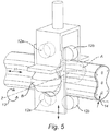
- Figure 5 shows a case wherein two friction wheels which are positioned at both sides of the rail do not have enough stability themselves to keep a virtual plane perpendicularly oriented to the tangent 11 of the rail. Stability around the z-axes can be obtained by introducing a stabilizing construction.
- a stabilizing construction To stabilize the rotation of a frame part about its z-axis ("roll") a set of four coupled guiding elements is introduced.
- the guiding elements are rollers 12a,b , but sliding elements could also be used.
- Two guiding elements 12a run ahead of the frame part and two 12b, run behind the frame part, when the frame part is moving in the direction 13.
- rollers 12b are rolling ahead of the driving wheels A, B, and rollers 12a are rolling behind wheels A, B. Since the guiding elements are placed on the left and the right side of the frame part, they need to be able to translate in the direction of the y-axis of the frame part and/or need sufficient distance 14 between rolls and tube to be able to drive through tight curves allowing room needed to drive through convex and concave curves to prevent the frame part from getting stuck on the rail on convex or concave rail sections, as depicted in figures 5a, 5b . Since the stabilizing construction has a substantially stable orientation on the rail. Because it prevents rotation with respect to the z-axis of the frame part after allowing a minimum or translation or rotation by the clearance, it keeps the frame part substantially perpendicular to the track.
- Figure 6 shows three smooth dented rails according to the invention.
- a single-dented shaped 15 is shown, formed from a tube with a circular cross section 15a, provided with a recess 15b.
- the recess 15b has a dent which has an essentially L-shaped cross-section, with smooth edges.
- the L-shape ensures grip to the wheel and prevents rotation of the frame about the axial rotation of the wheel and prevents rotation of the frame part about the tangential direction of the rail.
- a double-dented rail 16 is shown, which is made from a tube with a circular cross section, in which two dents 16a, 16b are formed.
- the dents may be seen as parts of the surface of the tube, where the surface is bent inside out.
- the two dents in the example shown each have a circumference equal to the original circumference of the tube the dent was formed from.
- the non-dented areas of the tube substantially do have the same radius as the non-dented tube's radius. The areas where the dents meet the original diameter are smooth.
- a triple-dented rail 17 with three recesses 17a, 17b, 17c is shown. Like the example with two dents, the dents are at equal mutual distances.
- Figure 7 shows a cross section of a frame part 18 displaying the crossing of its rotation axes 19 and 20 being substantially coincident with the virtual engagement point 21.
- Figure 8 shows another embodiment where at least one of the wheels 22 of the at least one pair of wheels of the frame part 18 is expansible within the recess 23 of the rail, to influence a normal force between the rail and the wheels, which multiplied by the friction coefficient is resulting in influencing the traction force.
- the expansibility is obtained by having two wheel parts that can be moved with respect to each other in the direction of the axis of rotation of the wheel.
- the wheel may engage the rail under pre-tension, and be expansible in the recess of the rail by means of a spring element 24, and/or an electrical, a hydraulic or pneumatic actuator.
- Figures 9a and 9b show yet a further embodiment wherein the axis of rotation of the wheels itself is rotatable about the direction 25 from the recess of the rail where the at least one wheel engages to the centreline of the rail.
- This has advantage that squeezing or wrenching of the wheels is reduced in twists 26 of the track.
- the wheels may follow the twist 26 in the track. This way the wheels are forced in a position where they encounter the least rolling resistance.
Landscapes
- Engineering & Computer Science (AREA)
- Mechanical Engineering (AREA)
- Transportation (AREA)
- Automation & Control Theory (AREA)
- Structural Engineering (AREA)
- Handcart (AREA)
- Types And Forms Of Lifts (AREA)
- Escalators And Moving Walkways (AREA)
- Lift-Guide Devices, And Elevator Ropes And Cables (AREA)
Description
- The present invention relates to a stair lift drive. In particular, the invention relates to a stair lift for use in combination with a smooth dented rail.
- Stair lifts are known in the art, and the drives applied may have gears, toothed racks, or friction drives.
EP 2 433 892 A1 - Although it may seem logically to leave out protrusions in the rail when disadvantages stick to them, so far, the protrusions have been necessary so far, and drives according to the state of the art have been unable to propel along a guide rail that is smooth and follows the outlines of a staircase naturally.
- It is therefore the goal of the present invention to overcome these drawbacks, or at least to offer a suitable alternative.
- The invention thereto proposes a stair lift drive, comprising a rail extending along a track, which is at least provided with one dent or recess that extends in a direction tangential to the rail; a frame part, provided with at least one set of wheels, of which at least one wheel engages on the rail in the at least recess, wherein the wheels are each rotatable about an axis which extends substantially perpendicular to the direction from the recess of the rail where the at least one wheel engages to the centreline of the rail as well as perpendicular to a direction tangential to the direction of the rail; a propulsion, to drive at least one of the wheels, wherein the running surfaces of the wheels engage at least a part of the recess in a form-fitting manner, characterised in that the cross section of the rail has a substantially smooth shape.
- In each frame part the resultant of the traction forces engages the rail in the so called engagement point. The engagement point is substantially coincide with the rotational axes, about which the frame part can rotate with respect to the mounting part. In case of one driven wheel the rotational axes cross each other at the engagement point, connecting the driven wheel with the rail. In case of two driven wheels opposite from each other, the engagement point is substantially coincided with the rotational axes of its frame section. As a result, the frame part does not pull itself out of alignment with the rail when all wheels are driven.
- The deeper the dent(s) in the tube, the smaller the difference between the lengths of the paths of the various wheels when driving the stair lift through curved and/or twisted sections, which further contributes to prevent or reduces misalignment and/or slip and/or wear. Furthermore the closer the driven wheels are to the centreline of the rail, the less need they have of being rotatable around an axis perpendicular to their rotational axes and perpendicular to the tangent of the centreline, crossing the centreline.
- In general, the rail will be positioned close to one side of the staircase, wherein the smooth shape of the rail is predominantly focussed on the absence of sharp corners and greasy racks, pointing towards the user of the stair lift. A smooth surface may for instance be defined as a surface having no edges with a smaller radius than 15 mm, or than 10 mm, or 5 mm. Therefor, the rail is safe to touch during use, and when the stair lift is idle. The smooth rail may be produced by making indentations in a substantially cylindrical tube, and it can be bent and twisted into multiple corners for forming a curved track. The rail substantially maintains its original diameter on the section where the rail is not dented, and the overall circumference can therefor remain substantially the same.
- In particular, the rail may be designed such that its cross section remains its same angular orientation throughout the track, but still, the drive according to the invention is less vulnerable for torsion occurring during production of the rail, since twisting and turning of the rail can be overcome by other parts of the drive, as will be described below. With a pair of wheels, two wheels pressing on the rail are intended. The presence of more wheels or sets of wheels is not excluded. The wheels may be located next to each other in the same recess, but can also be located opposite to each other in two opposing recesses, if present in the rail. The at least one wheel that engages in the recess of the rail determines the angular orientation of the frame about the axis of the rail. This wheel is not necessarily the driven wheel. Two or more recesses or dents provide the advantage that a more stable coupling to the rail is possible, also in a rotational direction about the direction tangential to the rail. The number of wheels is also not necessarily limited or equal to the number of recesses in the rail.
- The wheels engage the rail under the influence of friction. The use of friction wheels instead of for example toothed wheels allows the wheels to follow the smooth rail, along all its bends, twists and corners, without jamming or collision. The running surfaces of the wheels are typically pressed against matching running surfaces of recesses in the rail. Such running surfaces of the wheels can for instance be made out of polyurethane, like Vulkollan, commercially available from Bayer. Because the wheels engage at least part of the recess in a form-fitting manner, the wheels are able to support the drive and compensate for torsion about the direction tangential to the rail.
- In an embodiment of the present invention the rail has a substantially 8-shaped, apple-core shaped, single or multi-dented-tube shaped or lemniscates shaped cross section. This cross section can for instance be realised when a cylinder shaped or oval rail is on two opposing sides provided with recesses that extend over predominantly the whole length of the rail. This single or multiple-dented shape can easily be manufactured and can afterwards or at the time of forming the dents be bent into the desired shape to follow the desired contours of a staircase. The specifically shaped cross section also offers torsion stiffness and flexural rigidity as well as horizontal and vertical stabilisation and an orientation that prevents rotation of the stair lift around the rail. The rail can be formed by means of the method according to the European
Patent application EP 11 189 248.5 - In an embodiment the part of the recess wherein the substantially straight running surfaces engage the rail comprise an angle between 80 and 135 degrees. Herewith the grip and thus the traction force increases, so a higher traction force can be obtained with the same pressure from the wheel on the rail. Each dented area or recess comprises an angle along the circumference of the rail, which may be between 70 and 110, and in particular about 90 degrees for a rail with a single dent, between 60 and 90 degrees and in particular about 75 degrees for a rail with two dents and between 45 and 75 degrees and in particular about 60 degrees for a rail with three dents. The dent may comprise substantially straight section(s) to provide a surface to prevent rotation around the longitudinal axes of the rail. Consequently, the part of the wheel that encounters the rail then may have essentially the same shape as the shape of the tube's dent.
- Preferably the rail is a monorail, which is advantageous in that it requires less modification of the location where it is to be installed and in that it requires less space.
- In an embodiment, the pressure under which the wheels of the stair lift engage the recess of the rail can be adjustable, and therewith directly the maximum traction force, resulting from by the normal force on the driven wheels multiplied by a coefficient of friction. When the stair lift has to transport a heavy load over the rail, the normal force (and thus grip) needs to be larger compared to when a lighter load is transported. Vice versa, when a light load has to be transported, the application of high normal load would result in an inefficient transportation, since unnecessary amounts of rolling resistance have to be overcome to facilitate the transportation. Besides less aging and creep can be established.
- In order to apply an adjustable amount of normal force to the friction wheels, friction wheels that engage in one or more the recesses of the rail are forcible towards the rail for applying an increasing amount of pressure to the recess of the rail and therefor experience an increase in traction force.
- In order to move the wheels towards each other, at least one of the wheels can be equipped with an actuator, for instance hydraulic or pneumatic, to move it towards the other wheel(s). To supply hydraulic pressure to power the hydraulic actuator, a cylinder may be provided, which cylinder is arranged to build up hydraulic pressure based on the weight of the load or the user of the stair lift. In such a way a direct link between the load that has to be transported and the required pressure and friction, and therewith a load dependent clamping force, can be realised. Moreover, a clamping force ensures that the friction wheels are not running outside of the recess of the rail and keeps the frame part substantially perpendicular to a direction tangential to the (centreline of) the rail.
- In an embodiment, the wheels are each connected to a frame section, which is rotatable with respect to another frame section, about an axis of rotation axially with respect to the rail, in order to move the wheels toward each other. In this case, the frame sections are movable toward each other due to the rotation of both parts over a common axis, which can for instance coincide with the axis of transportation.
- In an embodiment the frame part also comprises a set of wheels or gliders for stabilisation over Z-axes or axis perpendicular to the centreline of the rail and perpendicular to the rotational axes of the driven wheels, which engage the rail out of the recess of the rail. These means ensure that the frame part follows the rail substantially perpendicular to the direction tangential to the (centreline of the) rail and prevent the frame part from losing track.
- The invention further relates to a combination of two frame parts, as described above, which are coupled to each other and are rotatable relative to each other in all directions, and are provided with support means for a load, such as a seat for a user of the stair lift. Two frame parts, of which each frame part comprises a set of wheels and which are coupled in a rotatable fashion, have the advantage of a combined driving force, and can follow each other during turns, twists and/or bends while offering a stable platform for supporting a user.
- The frame part may further comprise a support means for a load, such as a seat, which can be impressed relative to the support means by the weight of load or user, and wherein the support means are coupled to a hydraulic cylinder which is coupled to each of the hydraulic actuators to move the respectively first wheels towards the second wheels of the frame parts. The load of the stair lift can be distributed over both frame parts, whereas the load also dictated the clamping force and the amount of pressure and friction required to transport the load effectively. Instead of a hydraulic cylinder, other mechanisms like springs can also be used to force the wheels towards the rail.
- In another embodiment at least one of the wheels of the at least one pair of wheels of the first or second frame part is expansible within the recess of the rail, to influence a normal force between the rail and the wheels. Multiplied by the friction coefficient this normal force is resulting in influencing the maximum traction force. The wheel may engage the rail under pre-tension, and be expansible in the recess of the rail by means of a spring element, and/or an electrical, a hydraulic or pneumatic actuator.
- In an embodiment of the present invention the combination also comprises a device to correct the orientation of the support means around the coordinate system, as will be explained with reference to
figure 1 . These axes are all perpendicular to each other (orthogonal) and ensure the desired orientation or levelling of the seat of the stair lift in all directions, in order to maintain a steady orientation of the load. - In an embodiment of the invention, the combination also comprises a controller, to control the propulsion of the different frame parts in a master-slave configuration or in a symmetrical fashion.
- In yet a further embodiment the axis of rotation of the wheels itself is rotatable about the direction from the recess of the rail where the at least one wheel engages to the centreline of the rail. This has advantage that squeezing or wrenching of the wheels is reduced in twists of the track.
- The invention will now be elucidated into more detail with reference to the following figures, wherein:
-
Figure 1 shows a coordinate system used to indicate movements; -
Figure 2 shows a frame part according to the invention; -
Figure 3 shows a frame part with adjustable engaging pressure; -
Figure 4 shows a pre-tensioning system; -
Figure 5 ,5a, 5b show a stabilising constructions; -
Figure 6 shows three smooth dented rails according to the invention -
Figure 7 shows a cross section of a frame part displaying the crossing of its rotation axis being substantially coincident with the virtual engagement point; -
Figure 8 shows an expansible wheel according to the present invention; and -
Figures 9 a, b show wheels with a rotatable axis of rotation. -
Figure 1 shows the coordinate system as generally used to indicate movements. In order to designate the orientation of the drive system according to the present invention or elements thereof with respect to a rail, a system of coordinates is used. The x-axis is the local tangent to the centerline of the rail. For the rotation around the x, y and z axes the navigational and/or aviational terms pitch, yaw and roll are used respectively. Note that the drive moves in the direction of the x-axis, unlike vessels and planes, which move in the direction of the z-axis. In other words, the drive moves sideways. - In the figure, the reference numbers indicate the following:
- 101
- Right
- 102
- Pitch
- 103
- Yaw
- 104
- Longitudinal
- 105
- Roll
- 106
- Vertical
- 107
- Lateral Left
-
Figure 2 shows a frame part on arail 1 extending along a track, which is at least on one side of its width provided with arecess 2 that extends in adirection 3 tangential to the rail; aframe part 4, provided with at least one set of wheels (A, B), of which at least one wheel B (and in this case both wheels A, B) engage on therail 1 in the atleast recess 2, wherein the wheels are each rotatable about anaxis 5, 6 which extends substantially perpendicular to the direction from the recess of the rail where the at least one wheel presses to the centreline of therail 7 as well as perpendicular to thedirection 3 tangential to therail 1; apropulsion 8, 9, to drive the wheels (A, B), wherein the running surfaces of the wheels (A, B) engage at least a part of therecess 2 in a form-fitting manner, characterised in that the cross section of therail 1 has a substantially smooth shape (see alsofigure 8 ). - The rail in
figure 2 has a substantially dented tube cross section. This cross section can for instance be realised when a cylinder shaped or oval rail is on two opposing sides provided with recesses that extend over predominantly the whole length of the rail.Figure 3 shows a frame part schematically wherein the pressure under which the wheels of the stair lift engage the recess of the rail is adjustable. Two friction wheels (A and B) that engage on for instance opposite sides of the recesses in for instance an apple-core-shaped rail, are movable towards each other. For that purpose, the frame part (4) comprises a first section (4a) and a second section (4b), which are mutually rotatable about an axis (S). When these wheels are moved towards each other, they apply an increasing amount of pressure to the recess of the rail and therefor experience an increase in normal force which multiplied by the available friction allows in more traction force. In order to move the wheels towards each other, at least one of the wheels (B) can be equipped with a hydraulic actuator (HCB,figure 4 ), to move the first wheel (B) of the set towards the corresponding second wheel (A). To supply hydraulic pressure to power the hydraulic actuator, a cylinder (HCF,figure 4 ) may be provided, which cylinder may be arranged to build up hydraulic pressure based on the weight of the load or the user of the stair lift. The wheels are each connected to a frame section 4a, 4b, which is rotatable with respect to the other frame section 4b, 4a respectively, about an axis of rotation (S), in order to move the wheels (A, B) toward each other. - The hydraulic cylinder HCB is placed underneath friction wheel B, which is mounted to the frame part with hinge S. The distance HCB - S from the hydraulic cylinder to the hinge is larger than the distance B-S from friction wheel B to the axis of rotation (S), causing a leverage effect for the hydraulic cylinder.
-
Figure 4 shows a pre-tensioning system for a drive on arail 40 comprising twoframe parts 4, 4' designed to supplement the needed normal forces on four friction wheels A, B. C, D by means of hydraulic cylinders HCC, HCB, acting on two of the four wheels B, C present in the embodiment shown. A heavy user requires more traction and thus larger normal forces on the friction wheels than a light user. In order to load the friction wheels not more than needed, the initial intension is to make the hydraulic pressure dependent on the weight of the user by placing another hydraulic cylinder underneath the user platform. In case of an inclined rail section, the friction wheels A and D already experience a certain normal force as a result of the vertical force caused by the user platform, acting on the virtual centre ofgravity 41. Wheels B and C are equipped with hydraulic cylinders HCB and HCC respectively. The pre-tensioning force from HCB acts on wheel B, but also on wheel A. The same counts for hydraulic cylinder HCC on wheel C and D. The hydraulic pressure is obtained from hydraulic cylinder HCE, mounted underneath a seat 10. The system may also be split up into separate systems, one for each frame part. The system provides possibility to easily implement seat adjustment. A combination of springs, pneumatics and hydraulics may be used to generate required forces. -
Figure 5 shows a case wherein two friction wheels which are positioned at both sides of the rail do not have enough stability themselves to keep a virtual plane perpendicularly oriented to the tangent 11 of the rail. Stability around the z-axes can be obtained by introducing a stabilizing construction. To stabilize the rotation of a frame part about its z-axis ("roll") a set of four coupled guiding elements is introduced. In this example the guiding elements arerollers 12a,b , but sliding elements could also be used. Two guidingelements 12a run ahead of the frame part and two 12b, run behind the frame part, when the frame part is moving in thedirection 13. In case it is moving in opposite direction,rollers 12b are rolling ahead of the driving wheels A, B, androllers 12a are rolling behind wheels A, B. Since the guiding elements are placed on the left and the right side of the frame part, they need to be able to translate in the direction of the y-axis of the frame part and/or needsufficient distance 14 between rolls and tube to be able to drive through tight curves allowing room needed to drive through convex and concave curves to prevent the frame part from getting stuck on the rail on convex or concave rail sections, as depicted infigures 5a, 5b . Since the stabilizing construction has a substantially stable orientation on the rail. Because it prevents rotation with respect to the z-axis of the frame part after allowing a minimum or translation or rotation by the clearance, it keeps the frame part substantially perpendicular to the track. -
Figure 6 shows three smooth dented rails according to the invention. A single-dented shaped 15 is shown, formed from a tube with acircular cross section 15a, provided with arecess 15b. Therecess 15b has a dent which has an essentially L-shaped cross-section, with smooth edges. The L-shape ensures grip to the wheel and prevents rotation of the frame about the axial rotation of the wheel and prevents rotation of the frame part about the tangential direction of the rail. - A double-dented
rail 16 is shown, which is made from a tube with a circular cross section, in which twodents - Finally, a triple-dented
rail 17 with threerecesses -
Figure 7 shows a cross section of aframe part 18 displaying the crossing of its rotation axes 19 and 20 being substantially coincident with thevirtual engagement point 21. -
Figure 8 shows another embodiment where at least one of thewheels 22 of the at least one pair of wheels of theframe part 18 is expansible within therecess 23 of the rail, to influence a normal force between the rail and the wheels, which multiplied by the friction coefficient is resulting in influencing the traction force. The expansibility is obtained by having two wheel parts that can be moved with respect to each other in the direction of the axis of rotation of the wheel. The wheel may engage the rail under pre-tension, and be expansible in the recess of the rail by means of aspring element 24, and/or an electrical, a hydraulic or pneumatic actuator. -
Figures 9a and 9b show yet a further embodiment wherein the axis of rotation of the wheels itself is rotatable about thedirection 25 from the recess of the rail where the at least one wheel engages to the centreline of the rail. This has advantage that squeezing or wrenching of the wheels is reduced intwists 26 of the track. The wheels may follow thetwist 26 in the track. This way the wheels are forced in a position where they encounter the least rolling resistance.
Claims (15)
- Stair lift drive system, comprising- a rail (1) extending along a track, wherein- the cross section of the rail has a substantially smooth shape which is at least on one side of its circumference provided with a recess (2) that extends in a direction (3) tangential to the rail;- a frame part (4), provided with at least one set of wheels (A, B), of which at least one wheel engages on the rail in the at least recess, wherein the wheels are each rotatable about an axis (5, 6) which extends substantially perpendicular to the direction from the recess of the rail where the at least one wheel engages to the centreline of the rail as well as substantially perpendicular to the axial direction of the rail;- a propulsion (8, 9), to drive at least one of the wheels, wherein- the running surfaces of the at least one wheel engage at least a part of the recess in a form-fitting manner.
- Stair lift drive system according to claim 1 wherein the at least one wheel that engages on the rail in the at least recess determines the angular orientation of the frame part about the axis of the rail.
- Stair lift drive system according to any of the preceding claims, wherein the rail has a substantially apple core-or dented tube shaped cross section.
- Stair lift drive system according to any of the preceding claims, wherein the recess comprises at least one substantially straight section to provide a grip surface for the at least one wheel engaging said recess.
- Stair lift drive system according to any of the preceding claims, wherein the running surfaces which engage the rail comprise an angle between 80 and 135 degrees.
- Stair lift drive system according to any preceding claims wherein the rail is a monorail.
- Stair lift drive system drive according to any of the preceding claims, wherein the at least one wheel engage the rail under the influence of friction.
- Stair lift drive system according to any of the preceding claims, wherein the force under which the at least one wheel of the stair lift engage the recess of the rail is adjustable and/or controlled.
- Stair lift drive system according to claim 8, wherein two friction wheels that engage in the recesses of the rail, are forcible towards the rail.
- Stair lift drive system according to any of the preceding claims, wherein the axes perpendicular to the direction from the recess of the rail where the wheels engages to the centreline of the rail as well as substantially perpendicular to the axial direction of the rail cross one another in the centre of the cross section of the rail.
- Stair lift drive system according claim 9 or 10, wherein at least one of the wheels of the set is equipped with a hydraulic actuator, and/or a spring, and/or mechanical and/or electrical and/or pneumatic means, for moving the first wheel of the set towards the corresponding second wheel of the set.
- Stair lift drive system according to any of the preceding claims, comprising a cylinder, arranged to build up hydraulic pressure and/or force by a springload and/or pneumatic device based on the weight of the load or the user of the stair lift and/or inclination angle of the rail.
- Stair lift drive system according to any of the preceding claims, wherein the wheels of the set are each connected to a frame section, which is rotatable with respect to another frame section, about an axis of rotation tangentially with respect to the rail, in order to move the wheels toward each other.
- Stair lift drive system according to any of the preceding claims, comprising a set of wheels or gliders for stabilisation, which engage the rail in or out of the recess of the rail.
- Stair lift drive system according to any of the preceding claims wherein at least one of the wheels of the at least one pair of wheels of the first or second frame part is expansible within the recess of the rail, to influence a normal force between the rail and the wheels.
Applications Claiming Priority (2)
| Application Number | Priority Date | Filing Date | Title |
|---|---|---|---|
| NL2010012A NL2010012C2 (en) | 2012-12-19 | 2012-12-19 | Stair lift drive system for a smooth dented rail. |
| PCT/NL2013/050894 WO2014098573A2 (en) | 2012-12-19 | 2013-12-12 | Stair lift drive system for a smooth dented rail |
Publications (2)
| Publication Number | Publication Date |
|---|---|
| EP2935072A2 EP2935072A2 (en) | 2015-10-28 |
| EP2935072B1 true EP2935072B1 (en) | 2017-03-29 |
Family
ID=47790453
Family Applications (1)
| Application Number | Title | Priority Date | Filing Date |
|---|---|---|---|
| EP13818482.5A Active EP2935072B1 (en) | 2012-12-19 | 2013-12-12 | Stair lift drive system for a smooth dented rail |
Country Status (6)
| Country | Link |
|---|---|
| EP (1) | EP2935072B1 (en) |
| JP (1) | JP6414825B2 (en) |
| CN (1) | CN104995119B (en) |
| ES (1) | ES2628978T3 (en) |
| NL (1) | NL2010012C2 (en) |
| WO (1) | WO2014098573A2 (en) |
Families Citing this family (7)
| Publication number | Priority date | Publication date | Assignee | Title |
|---|---|---|---|---|
| NL2014685B1 (en) | 2015-04-21 | 2017-01-25 | Thyssenkrupp Ag | Chair Stair Lift. |
| CN205892421U (en) * | 2016-04-20 | 2017-01-18 | 深圳职业技术学院 | Transportation booster unit |
| NL2017793B1 (en) | 2016-11-15 | 2018-06-01 | Morpho Bv | Security document with positive and negative authentication tilt images |
| CN106865386A (en) * | 2017-04-05 | 2017-06-20 | 深圳市晓控通信科技有限公司 | A kind of Intelligent escalator manipulator taken for old man based on Internet of Things |
| CN111704002A (en) * | 2020-06-08 | 2020-09-25 | 泉州市泉港区竞丰工业设计服务中心 | A freight robot guider for handrail stair climb |
| GB202010021D0 (en) * | 2020-06-30 | 2020-08-12 | Stannah Stairlifts Ltd | Improvements in or relating to stairlifts |
| EP4431433A1 (en) | 2023-03-16 | 2024-09-18 | Wheel Up | Transport system for conveying vehicle |
Family Cites Families (13)
| Publication number | Priority date | Publication date | Assignee | Title |
|---|---|---|---|---|
| US3134481A (en) * | 1962-11-30 | 1964-05-26 | Conveyor Corp Of America | Conveyor |
| NL1001327C2 (en) * | 1995-10-02 | 1997-04-03 | Thyssen De Reus Bv | Running gear for a drive device for a rail guided displacement device. |
| IT1293909B1 (en) * | 1997-05-28 | 1999-03-11 | Calogero Provenzano | STAIRCASE DEVICE, PARTICULARLY FOR DISABLED PEOPLE. |
| JP4275246B2 (en) * | 1998-11-02 | 2009-06-10 | クマリフト株式会社 | Chair type stair lift |
| WO2001027003A1 (en) * | 1999-10-13 | 2001-04-19 | Robert Greeley | Trolley-type monorail conveyor system |
| US20040104078A1 (en) * | 2001-02-12 | 2004-06-03 | Szentistvany Andreas Csaba | Rail and carriage for stairlifts |
| GB0226418D0 (en) * | 2002-11-13 | 2002-12-18 | Stannah Stairlifts Ltd | Improvements in or relating to stairlifts |
| GB2409446B (en) * | 2003-12-10 | 2006-08-30 | Stannah Stairlifts Ltd | Improvements in or relating to stairlifts |
| GB0404647D0 (en) * | 2004-03-02 | 2004-04-07 | Stannah Stairlifts Ltd | Improvements in or relating to stairlifts |
| CN2853731Y (en) * | 2005-11-28 | 2007-01-03 | 周度 | Rail device with hook for drawing material upstairs |
| GB0620861D0 (en) * | 2006-10-20 | 2006-11-29 | Stannah Stairlifts Ltd | Improvements in or relating to stairlifts |
| NL2005398C2 (en) * | 2010-09-27 | 2012-03-28 | Handicare Stairlifts B V | Friction drive lift. |
| NL2005957C2 (en) * | 2011-01-06 | 2012-07-10 | Handicare Stairlifts B V | Transport unit for climbing or descending a slope or stairs. |
-
2012
- 2012-12-19 NL NL2010012A patent/NL2010012C2/en active
-
2013
- 2013-12-12 WO PCT/NL2013/050894 patent/WO2014098573A2/en not_active Ceased
- 2013-12-12 CN CN201380073234.2A patent/CN104995119B/en active Active
- 2013-12-12 EP EP13818482.5A patent/EP2935072B1/en active Active
- 2013-12-12 ES ES13818482.5T patent/ES2628978T3/en active Active
- 2013-12-12 JP JP2015549294A patent/JP6414825B2/en active Active
Non-Patent Citations (1)
| Title |
|---|
| None * |
Also Published As
| Publication number | Publication date |
|---|---|
| WO2014098573A2 (en) | 2014-06-26 |
| NL2010012C2 (en) | 2014-06-23 |
| JP2016505467A (en) | 2016-02-25 |
| ES2628978T3 (en) | 2017-08-04 |
| WO2014098573A3 (en) | 2014-09-04 |
| JP6414825B2 (en) | 2018-10-31 |
| CN104995119A (en) | 2015-10-21 |
| EP2935072A2 (en) | 2015-10-28 |
| CN104995119B (en) | 2018-05-01 |
Similar Documents
| Publication | Publication Date | Title |
|---|---|---|
| WO2014098573A2 (en) | Stair lift drive system for a smooth dented rail | |
| KR102691869B1 (en) | Corner module apparatus for vehicle | |
| CN102605985B (en) | Multilayer garage without avoidance | |
| KR102688427B1 (en) | Corner module apparatus for vehicle | |
| DE19534291C2 (en) | Shelf system with a storage and retrieval unit guided on rails | |
| EP2935074B1 (en) | Stair lift drive with rotatable mounting part for seat | |
| EP3292068B1 (en) | Tread element for people conveyor comprising a cantilever arm | |
| KR101947433B1 (en) | Driving apparatus with multiple degree of freedom for monorail and bogie frame with the apparatus | |
| NL2010013C2 (en) | Stair lift drive. | |
| MX2011005972A (en) | Curved building panel, building structure, panel curving system and methods for making curved building panels. | |
| EP3209590B1 (en) | A stairlift, for transporting a load along a staircase | |
| CN105016243A (en) | Four-column chain type lift | |
| EP2452909A1 (en) | Rail follower apparatus for stair lift | |
| CN115092199A (en) | Rail transport equipment and braking system suitable for high-speed railway | |
| JPH06156962A (en) | Comveyor element variable in length | |
| US5775477A (en) | Drive system for curved escalator | |
| US20150033979A1 (en) | Rail carriage group | |
| CN203160075U (en) | Device for machining rolling surface of rail laid in track | |
| JP2000226170A (en) | A moving device arranged to guide the vehicle along at least two rails | |
| US20010015315A1 (en) | Turning-around-type continuous conveying apparatus | |
| JP3641617B2 (en) | Bridge girder delivery method | |
| CN1182711A (en) | Transfer of cab horizontally between elevator and bogey platforms | |
| EP2570378B1 (en) | Bidirectional moving walkway | |
| CN205061464U (en) | Four post chain elevators | |
| WO2010147174A1 (en) | Conveyor |
Legal Events
| Date | Code | Title | Description |
|---|---|---|---|
| PUAI | Public reference made under article 153(3) epc to a published international application that has entered the european phase |
Free format text: ORIGINAL CODE: 0009012 |
|
| 17P | Request for examination filed |
Effective date: 20150717 |
|
| AK | Designated contracting states |
Kind code of ref document: A2 Designated state(s): AL AT BE BG CH CY CZ DE DK EE ES FI FR GB GR HR HU IE IS IT LI LT LU LV MC MK MT NL NO PL PT RO RS SE SI SK SM TR |
|
| AX | Request for extension of the european patent |
Extension state: BA ME |
|
| 17Q | First examination report despatched |
Effective date: 20160215 |
|
| DAX | Request for extension of the european patent (deleted) | ||
| GRAP | Despatch of communication of intention to grant a patent |
Free format text: ORIGINAL CODE: EPIDOSNIGR1 |
|
| INTG | Intention to grant announced |
Effective date: 20161222 |
|
| GRAS | Grant fee paid |
Free format text: ORIGINAL CODE: EPIDOSNIGR3 |
|
| GRAA | (expected) grant |
Free format text: ORIGINAL CODE: 0009210 |
|
| AK | Designated contracting states |
Kind code of ref document: B1 Designated state(s): AL AT BE BG CH CY CZ DE DK EE ES FI FR GB GR HR HU IE IS IT LI LT LU LV MC MK MT NL NO PL PT RO RS SE SI SK SM TR |
|
| REG | Reference to a national code |
Ref country code: GB Ref legal event code: FG4D |
|
| REG | Reference to a national code |
Ref country code: CH Ref legal event code: EP |
|
| REG | Reference to a national code |
Ref country code: AT Ref legal event code: REF Ref document number: 879557 Country of ref document: AT Kind code of ref document: T Effective date: 20170415 |
|
| REG | Reference to a national code |
Ref country code: IE Ref legal event code: FG4D |
|
| REG | Reference to a national code |
Ref country code: DE Ref legal event code: R096 Ref document number: 602013019266 Country of ref document: DE |
|
| PG25 | Lapsed in a contracting state [announced via postgrant information from national office to epo] |
Ref country code: FI Free format text: LAPSE BECAUSE OF FAILURE TO SUBMIT A TRANSLATION OF THE DESCRIPTION OR TO PAY THE FEE WITHIN THE PRESCRIBED TIME-LIMIT Effective date: 20170329 Ref country code: GR Free format text: LAPSE BECAUSE OF FAILURE TO SUBMIT A TRANSLATION OF THE DESCRIPTION OR TO PAY THE FEE WITHIN THE PRESCRIBED TIME-LIMIT Effective date: 20170630 Ref country code: NO Free format text: LAPSE BECAUSE OF FAILURE TO SUBMIT A TRANSLATION OF THE DESCRIPTION OR TO PAY THE FEE WITHIN THE PRESCRIBED TIME-LIMIT Effective date: 20170629 Ref country code: HR Free format text: LAPSE BECAUSE OF FAILURE TO SUBMIT A TRANSLATION OF THE DESCRIPTION OR TO PAY THE FEE WITHIN THE PRESCRIBED TIME-LIMIT Effective date: 20170329 Ref country code: LT Free format text: LAPSE BECAUSE OF FAILURE TO SUBMIT A TRANSLATION OF THE DESCRIPTION OR TO PAY THE FEE WITHIN THE PRESCRIBED TIME-LIMIT Effective date: 20170329 |
|
| REG | Reference to a national code |
Ref country code: NL Ref legal event code: MP Effective date: 20170329 |
|
| REG | Reference to a national code |
Ref country code: ES Ref legal event code: FG2A Ref document number: 2628978 Country of ref document: ES Kind code of ref document: T3 Effective date: 20170804 |
|
| REG | Reference to a national code |
Ref country code: AT Ref legal event code: MK05 Ref document number: 879557 Country of ref document: AT Kind code of ref document: T Effective date: 20170329 |
|
| PG25 | Lapsed in a contracting state [announced via postgrant information from national office to epo] |
Ref country code: RS Free format text: LAPSE BECAUSE OF FAILURE TO SUBMIT A TRANSLATION OF THE DESCRIPTION OR TO PAY THE FEE WITHIN THE PRESCRIBED TIME-LIMIT Effective date: 20170329 Ref country code: SE Free format text: LAPSE BECAUSE OF FAILURE TO SUBMIT A TRANSLATION OF THE DESCRIPTION OR TO PAY THE FEE WITHIN THE PRESCRIBED TIME-LIMIT Effective date: 20170329 Ref country code: BG Free format text: LAPSE BECAUSE OF FAILURE TO SUBMIT A TRANSLATION OF THE DESCRIPTION OR TO PAY THE FEE WITHIN THE PRESCRIBED TIME-LIMIT Effective date: 20170629 Ref country code: LV Free format text: LAPSE BECAUSE OF FAILURE TO SUBMIT A TRANSLATION OF THE DESCRIPTION OR TO PAY THE FEE WITHIN THE PRESCRIBED TIME-LIMIT Effective date: 20170329 |
|
| PG25 | Lapsed in a contracting state [announced via postgrant information from national office to epo] |
Ref country code: NL Free format text: LAPSE BECAUSE OF FAILURE TO SUBMIT A TRANSLATION OF THE DESCRIPTION OR TO PAY THE FEE WITHIN THE PRESCRIBED TIME-LIMIT Effective date: 20170329 |
|
| PG25 | Lapsed in a contracting state [announced via postgrant information from national office to epo] |
Ref country code: CZ Free format text: LAPSE BECAUSE OF FAILURE TO SUBMIT A TRANSLATION OF THE DESCRIPTION OR TO PAY THE FEE WITHIN THE PRESCRIBED TIME-LIMIT Effective date: 20170329 Ref country code: AT Free format text: LAPSE BECAUSE OF FAILURE TO SUBMIT A TRANSLATION OF THE DESCRIPTION OR TO PAY THE FEE WITHIN THE PRESCRIBED TIME-LIMIT Effective date: 20170329 Ref country code: SK Free format text: LAPSE BECAUSE OF FAILURE TO SUBMIT A TRANSLATION OF THE DESCRIPTION OR TO PAY THE FEE WITHIN THE PRESCRIBED TIME-LIMIT Effective date: 20170329 Ref country code: RO Free format text: LAPSE BECAUSE OF FAILURE TO SUBMIT A TRANSLATION OF THE DESCRIPTION OR TO PAY THE FEE WITHIN THE PRESCRIBED TIME-LIMIT Effective date: 20170329 Ref country code: EE Free format text: LAPSE BECAUSE OF FAILURE TO SUBMIT A TRANSLATION OF THE DESCRIPTION OR TO PAY THE FEE WITHIN THE PRESCRIBED TIME-LIMIT Effective date: 20170329 |
|
| RAP2 | Party data changed (patent owner data changed or rights of a patent transferred) |
Owner name: THYSSENKRUPP ACCESSIBILITY B.V. |
|
| PG25 | Lapsed in a contracting state [announced via postgrant information from national office to epo] |
Ref country code: SM Free format text: LAPSE BECAUSE OF FAILURE TO SUBMIT A TRANSLATION OF THE DESCRIPTION OR TO PAY THE FEE WITHIN THE PRESCRIBED TIME-LIMIT Effective date: 20170329 Ref country code: PL Free format text: LAPSE BECAUSE OF FAILURE TO SUBMIT A TRANSLATION OF THE DESCRIPTION OR TO PAY THE FEE WITHIN THE PRESCRIBED TIME-LIMIT Effective date: 20170329 Ref country code: IS Free format text: LAPSE BECAUSE OF FAILURE TO SUBMIT A TRANSLATION OF THE DESCRIPTION OR TO PAY THE FEE WITHIN THE PRESCRIBED TIME-LIMIT Effective date: 20170729 |
|
| REG | Reference to a national code |
Ref country code: FR Ref legal event code: PLFP Year of fee payment: 5 |
|
| REG | Reference to a national code |
Ref country code: DE Ref legal event code: R097 Ref document number: 602013019266 Country of ref document: DE |
|
| PG25 | Lapsed in a contracting state [announced via postgrant information from national office to epo] |
Ref country code: DK Free format text: LAPSE BECAUSE OF FAILURE TO SUBMIT A TRANSLATION OF THE DESCRIPTION OR TO PAY THE FEE WITHIN THE PRESCRIBED TIME-LIMIT Effective date: 20170329 |
|
| PLBE | No opposition filed within time limit |
Free format text: ORIGINAL CODE: 0009261 |
|
| STAA | Information on the status of an ep patent application or granted ep patent |
Free format text: STATUS: NO OPPOSITION FILED WITHIN TIME LIMIT |
|
| 26N | No opposition filed |
Effective date: 20180103 |
|
| REG | Reference to a national code |
Ref country code: DE Ref legal event code: R081 Ref document number: 602013019266 Country of ref document: DE Owner name: THYSSENKRUPP STAIRLIFTS B.V., NL Free format text: FORMER OWNER: THYSSENKRUPP ACCESSIBILITY B.V., KRIMPEN AAN DEN IJSSEL, NL |
|
| PG25 | Lapsed in a contracting state [announced via postgrant information from national office to epo] |
Ref country code: SI Free format text: LAPSE BECAUSE OF FAILURE TO SUBMIT A TRANSLATION OF THE DESCRIPTION OR TO PAY THE FEE WITHIN THE PRESCRIBED TIME-LIMIT Effective date: 20170329 |
|
| REG | Reference to a national code |
Ref country code: CH Ref legal event code: PL |
|
| REG | Reference to a national code |
Ref country code: IE Ref legal event code: MM4A |
|
| PG25 | Lapsed in a contracting state [announced via postgrant information from national office to epo] |
Ref country code: LU Free format text: LAPSE BECAUSE OF NON-PAYMENT OF DUE FEES Effective date: 20171212 Ref country code: MT Free format text: LAPSE BECAUSE OF NON-PAYMENT OF DUE FEES Effective date: 20171212 |
|
| PG25 | Lapsed in a contracting state [announced via postgrant information from national office to epo] |
Ref country code: IE Free format text: LAPSE BECAUSE OF NON-PAYMENT OF DUE FEES Effective date: 20171212 |
|
| REG | Reference to a national code |
Ref country code: DE Ref legal event code: R083 Ref document number: 602013019266 Country of ref document: DE |
|
| PG25 | Lapsed in a contracting state [announced via postgrant information from national office to epo] |
Ref country code: LI Free format text: LAPSE BECAUSE OF NON-PAYMENT OF DUE FEES Effective date: 20171231 Ref country code: CH Free format text: LAPSE BECAUSE OF NON-PAYMENT OF DUE FEES Effective date: 20171231 |
|
| PG25 | Lapsed in a contracting state [announced via postgrant information from national office to epo] |
Ref country code: MC Free format text: LAPSE BECAUSE OF FAILURE TO SUBMIT A TRANSLATION OF THE DESCRIPTION OR TO PAY THE FEE WITHIN THE PRESCRIBED TIME-LIMIT Effective date: 20170329 Ref country code: HU Free format text: LAPSE BECAUSE OF FAILURE TO SUBMIT A TRANSLATION OF THE DESCRIPTION OR TO PAY THE FEE WITHIN THE PRESCRIBED TIME-LIMIT; INVALID AB INITIO Effective date: 20131212 |
|
| PG25 | Lapsed in a contracting state [announced via postgrant information from national office to epo] |
Ref country code: CY Free format text: LAPSE BECAUSE OF FAILURE TO SUBMIT A TRANSLATION OF THE DESCRIPTION OR TO PAY THE FEE WITHIN THE PRESCRIBED TIME-LIMIT Effective date: 20170329 |
|
| PG25 | Lapsed in a contracting state [announced via postgrant information from national office to epo] |
Ref country code: MK Free format text: LAPSE BECAUSE OF FAILURE TO SUBMIT A TRANSLATION OF THE DESCRIPTION OR TO PAY THE FEE WITHIN THE PRESCRIBED TIME-LIMIT Effective date: 20170329 |
|
| PG25 | Lapsed in a contracting state [announced via postgrant information from national office to epo] |
Ref country code: TR Free format text: LAPSE BECAUSE OF FAILURE TO SUBMIT A TRANSLATION OF THE DESCRIPTION OR TO PAY THE FEE WITHIN THE PRESCRIBED TIME-LIMIT Effective date: 20170329 |
|
| PG25 | Lapsed in a contracting state [announced via postgrant information from national office to epo] |
Ref country code: PT Free format text: LAPSE BECAUSE OF FAILURE TO SUBMIT A TRANSLATION OF THE DESCRIPTION OR TO PAY THE FEE WITHIN THE PRESCRIBED TIME-LIMIT Effective date: 20170329 |
|
| PG25 | Lapsed in a contracting state [announced via postgrant information from national office to epo] |
Ref country code: AL Free format text: LAPSE BECAUSE OF FAILURE TO SUBMIT A TRANSLATION OF THE DESCRIPTION OR TO PAY THE FEE WITHIN THE PRESCRIBED TIME-LIMIT Effective date: 20170329 |
|
| P01 | Opt-out of the competence of the unified patent court (upc) registered |
Effective date: 20230526 |
|
| REG | Reference to a national code |
Ref country code: DE Ref legal event code: R081 Ref document number: 602013019266 Country of ref document: DE Owner name: TK HOME SOLUTIONS B.V., NL Free format text: FORMER OWNER: THYSSENKRUPP STAIRLIFTS B.V., KRIMPEN AAN DEN IJSSEL, NL |
|
| REG | Reference to a national code |
Ref country code: BE Ref legal event code: HC Owner name: THYSSENKRUPP STAIRLIFTS B.V.; NL Free format text: DETAILS ASSIGNMENT: CHANGE OF OWNER(S), CHANGE OF OWNER(S) NAME; FORMER OWNER NAME: THYSSENKRUPP STAIRLIFTS B.V. Effective date: 20240801 |
|
| PGFP | Annual fee paid to national office [announced via postgrant information from national office to epo] |
Ref country code: DE Payment date: 20251211 Year of fee payment: 13 |
|
| PGFP | Annual fee paid to national office [announced via postgrant information from national office to epo] |
Ref country code: GB Payment date: 20251219 Year of fee payment: 13 |
|
| PGFP | Annual fee paid to national office [announced via postgrant information from national office to epo] |
Ref country code: IT Payment date: 20251223 Year of fee payment: 13 |
|
| PGFP | Annual fee paid to national office [announced via postgrant information from national office to epo] |
Ref country code: FR Payment date: 20251223 Year of fee payment: 13 |
|
| PGFP | Annual fee paid to national office [announced via postgrant information from national office to epo] |
Ref country code: BE Payment date: 20251219 Year of fee payment: 13 |
|
| PGFP | Annual fee paid to national office [announced via postgrant information from national office to epo] |
Ref country code: ES Payment date: 20260130 Year of fee payment: 13 |