EP2934937B1 - Pedaleinheit für ein kfz - Google Patents
Pedaleinheit für ein kfz Download PDFInfo
- Publication number
- EP2934937B1 EP2934937B1 EP13818201.9A EP13818201A EP2934937B1 EP 2934937 B1 EP2934937 B1 EP 2934937B1 EP 13818201 A EP13818201 A EP 13818201A EP 2934937 B1 EP2934937 B1 EP 2934937B1
- Authority
- EP
- European Patent Office
- Prior art keywords
- pedal
- gear
- motor
- gearing
- unit according
- Prior art date
- Legal status (The legal status is an assumption and is not a legal conclusion. Google has not performed a legal analysis and makes no representation as to the accuracy of the status listed.)
- Not-in-force
Links
Images



Classifications
-
- B—PERFORMING OPERATIONS; TRANSPORTING
- B60—VEHICLES IN GENERAL
- B60K—ARRANGEMENT OR MOUNTING OF PROPULSION UNITS OR OF TRANSMISSIONS IN VEHICLES; ARRANGEMENT OR MOUNTING OF PLURAL DIVERSE PRIME-MOVERS IN VEHICLES; AUXILIARY DRIVES FOR VEHICLES; INSTRUMENTATION OR DASHBOARDS FOR VEHICLES; ARRANGEMENTS IN CONNECTION WITH COOLING, AIR INTAKE, GAS EXHAUST OR FUEL SUPPLY OF PROPULSION UNITS IN VEHICLES
- B60K26/00—Arrangement or mounting of propulsion-unit control devices in vehicles
- B60K26/02—Arrangement or mounting of propulsion-unit control devices in vehicles of initiating means or elements
-
- F—MECHANICAL ENGINEERING; LIGHTING; HEATING; WEAPONS; BLASTING
- F16—ENGINEERING ELEMENTS AND UNITS; GENERAL MEASURES FOR PRODUCING AND MAINTAINING EFFECTIVE FUNCTIONING OF MACHINES OR INSTALLATIONS; THERMAL INSULATION IN GENERAL
- F16H—GEARING
- F16H19/00—Gearings comprising essentially only toothed gears or friction members and not capable of conveying indefinitely-continuing rotary motion
- F16H19/001—Gearings comprising essentially only toothed gears or friction members and not capable of conveying indefinitely-continuing rotary motion for conveying reciprocating or limited rotary motion
-
- G—PHYSICS
- G05—CONTROLLING; REGULATING
- G05G—CONTROL DEVICES OR SYSTEMS INSOFAR AS CHARACTERISED BY MECHANICAL FEATURES ONLY
- G05G5/00—Means for preventing, limiting or returning the movements of parts of a control mechanism, e.g. locking controlling member
- G05G5/03—Means for enhancing the operator's awareness of arrival of the controlling member at a command or datum position; Providing feel, e.g. means for creating a counterforce
-
- B—PERFORMING OPERATIONS; TRANSPORTING
- B60—VEHICLES IN GENERAL
- B60K—ARRANGEMENT OR MOUNTING OF PROPULSION UNITS OR OF TRANSMISSIONS IN VEHICLES; ARRANGEMENT OR MOUNTING OF PLURAL DIVERSE PRIME-MOVERS IN VEHICLES; AUXILIARY DRIVES FOR VEHICLES; INSTRUMENTATION OR DASHBOARDS FOR VEHICLES; ARRANGEMENTS IN CONNECTION WITH COOLING, AIR INTAKE, GAS EXHAUST OR FUEL SUPPLY OF PROPULSION UNITS IN VEHICLES
- B60K26/00—Arrangement or mounting of propulsion-unit control devices in vehicles
- B60K26/02—Arrangement or mounting of propulsion-unit control devices in vehicles of initiating means or elements
- B60K26/021—Arrangement or mounting of propulsion-unit control devices in vehicles of initiating means or elements with means for providing feel, e.g. by changing pedal force characteristics
- B60K2026/023—Arrangement or mounting of propulsion-unit control devices in vehicles of initiating means or elements with means for providing feel, e.g. by changing pedal force characteristics with electrical means to generate counter force or torque
-
- G—PHYSICS
- G05—CONTROLLING; REGULATING
- G05G—CONTROL DEVICES OR SYSTEMS INSOFAR AS CHARACTERISED BY MECHANICAL FEATURES ONLY
- G05G1/00—Controlling members, e.g. knobs or handles; Assemblies or arrangements thereof; Indicating position of controlling members
- G05G1/30—Controlling members actuated by foot
- G05G1/44—Controlling members actuated by foot pivoting
Definitions
- the invention relates to a pedal unit for a motor vehicle.
- the invention relates to a pedal unit, in which an electric motor for generating a counteracting the operation of the pedal element opposing force is provided.
- Known pedal units have a fixed base element and a pedal element which can be deflected in an actuating direction relative to this base element.
- the engine of a vehicle is controlled by the operating position of the pedal element.
- the operating position d. H. the position of the pedal element between a basic position (idle) and a maximum position (full throttle), determined in today's conventional e-gas pedal units by means of a sensor and transmitted as an electrical signal to a control unit.
- WO-A-03/039899 a number of different embodiments of pedal units with additional restoring force.
- an electromechanical actuator By an electromechanical actuator, an additional actuating force is provided in a pedal element in the deviation of the actual speed of a vehicle from a desired speed. Under no circumstances should the actuator independently increase the speed of the vehicle and also be ensured that the driver always retains full control of the vehicle and accordingly actuate the accelerator pedal against the additional force, so they can "transgress".
- EP 1602 520 A1 describes a pedal unit with a pedal element which is coupled to a rotary element.
- a torque motor is provided which has a number of field coils on the stator and permanent magnet elements on the rotor.
- the rotary element is via a freewheel coupling unit with directly connected to the rotor without a gearbox.
- the freewheel coupling unit couples the rotor and the rotary element when moving in the direction of actuation, but allows a separate movement against the actuation direction.
- the EP-A-2578431 describes an accelerator pedal in which a rotary member is rotatably arranged. A curved surface is in contact with an element having a convexly curved outer surface. The element has a toothed area which is coupled to a reduction gear.
- the DE 10 2010 063 409 A1 describes an accelerator pedal device with a pedal element that is movably arranged relative to a base element.
- a rotary member is disposed on the base member and coupled to the pedal member so that movement of the pedal member results in rotation of the rotary member.
- a link element is provided on the base element. When the pedal element is actuated, the rotary element engages with the link element at an engagement position. For a further actuation, a force threshold of the actuating force is to be overcome from the engagement position.
- the link element is pivotable about the axis of rotation of the rotary member and adjustable by means of a spindle drive.
- a transmission device in the US 2012/0255385 A1
- the drive gear includes first and second gear portions coaxially arranged with each other.
- the gear radius of the toothed areas deviates from each other.
- the toothed areas are arranged spaced apart from one another in the circumferential direction.
- the driven gear includes a gear portion that engages the first gear portion.
- the pedal unit according to the invention comprises a rotary element, preferably a rotary lever, which is coupled to a pedal element, preferably a pedal plate, so that the rotary element rotates upon deflection of the pedal element with respect to a fixed base element.
- This coupling is possible, for example, via a coupling lever.
- an electric motor for generating a force is provided according to the invention, so that by driving the electric motor, an (additional) counterforce against the operation of the pedal element can be applied.
- a counterforce that i. A. in addition to the force of a return element is felt by the operator and is used to signal various operating conditions of the car, eg. Excessive speed, unfavorable fuel consumption, etc.
- the force is always opposite to the direction of actuation, so is to return the pedal element in the direction directed to a basic position.
- a transmission is provided according to the invention for coupling between the rotary member and the electric motor.
- the coupling is preferably such that the motor shaft is coupled synchronously with the rotary element at least during movement in the direction of actuation.
- the transmission is preferably a reduction gear, which converts a higher speed on the engine in a lower speed on the rotary member), but it is a coupling understood in which each movement of the rotary member in Actuation direction without slip and / or intermediate freewheel to a movement of the motor shaft leads.
- the synchronous coupling as will be explained in more detail below, but preferably given only in the direction of actuation;
- the motor is preferably decoupled from the rotary element in the opposite direction by a freewheel coupling element.
- the transmission is at least partially designed as a gear transmission, wherein at least one specially designed gear element is used.
- a "gear member” is understood to mean each component rotatable about an axis with a toothing which is provided or suitable for a power transmission for engagement in a counter-toothing of another member. It does not have to be a gear in the conventional sense, i. not necessarily have a round shape. On the contrary, the inventively provided gear element differs in shape from conventional gears.
- the gear element comprises at least a first and a second toothed area, which have different toothing radii. Starting from an axis about which the specially designed gear element is rotatable, it comprises rigidly interconnected (and preferably integrally formed with each other) the first and second toothed area. In this case, each of the two toothed areas does not extend over a full circumference, but in each case only over a partial circumference, d. H. a part of a full circle.
- the first and the second toothed region lie in one plane, ie. H. in that at least one part of the toothing of the first toothing region and at least one part of the toothing of the second toothed region are located in a plane arranged perpendicular to the axis of rotation of the toothed wheel element.
- the gear element is used by the different toothing radii (preferably equal tooth pitch) as a gear stage in which preferably a reduction takes place, ie that in the power flow, a higher speed at the motor side Coupling of the gear member is converted into a lower speed on the rotating element-side coupling.
- This implementation takes place in a plane so that the transmission can be particularly compact and the space is well utilized.
- the use of gearing areas that extend only over sub-ranges also ensures a compact design and saves material and weight. It is possible because the operating range of the pedal element between a basic position (idle) and a full-action position (full throttle) is clearly defined and clearly limited, for example. At operating angle of 45 ° or less. Accordingly, the transmission can be designed so that over the entire operating range no complete rotation of the gear element takes place and so the use of only partial amounts sufficient.
- the specially shaped gear element form a significant gradation within the transmission.
- the second tooth radius may be in the range of 1.3 to 3 times the first tooth radius, preferably 1.5 to 2.5 times.
- the partial circumference covered by the toothing areas may, for example, account for 45 ° to 270 °, preferably 90 ° to 220 °. It is, as is clear from the preferred embodiments, also an overlap possible, d. H. that the sum of the sub-scopes is greater than 360 °.
- an undercut arrangement of the first and second toothing region can serve.
- the invention allows a pedal unit with a simple structure in which can be achieved despite compact dimensions, a good coupling of the opposing forces of the electric motor.
- the transmission comprises, in addition to the first gear element with two toothed regions which each extend over only a partial circumference, and a second gear element, in which at least one toothed region extends only over a partial circumference.
- the second gear element can, in particular if it is arranged on the rotational element side with respect to the first gear element is a toothed area with a small partial circumference of, for example, only 15 - 35 ° include, for example.
- a toothed lever In the form of a toothed lever.
- two gear elements are in engagement with each other in their toothed areas, wherein a part of a first gear element can be received in a recess of a second gear element to increase the range of motion.
- the gear elements are preferably provided as a spur gear with mutually parallel spaced axes. More preferably, the toothing areas lie in a common plane.
- a recess is formed in a region which is preferably outside of the meshing toothed region. In at least one gear position, a part of the first gear element, preferably one end of its toothed region, can then be received in the recess formed on the second gear element. This allows a particularly compact structure and yet an increased range of motion.
- the transmission has a first gear pair between a pinion of the motor and a first gear member. Furthermore, the transmission preferably has a second gear pairing between the first gear element and a second gear element. More preferably, the second gear member is coupled to the rotary member, preferably in a common axis.
- the above-mentioned first gear element is preferably the gear element formed according to the invention with two different toothing regions. Such a structure has proved to be suitable in a particularly compact structure as for the coupling of a motor to a pedal element.
- the toothed areas on the gear element are formed as two outer spur gear teeth with different toothing diameter.
- at least one of the toothed areas may be formed as internal toothing. This allows a particularly compact arrangement, in particular in interaction with a pinion received within the internal toothing.
- the transmission is preferably designed as at least two-stage transmission. At least one step of the transmission, preferably at several and particularly preferably at all stages, an at least partially oblique toothing may be provided.
- the transmission is preferably designed as a reduction gear with a reduction ratio of at least 2: 1, preferably 5: to 30: designed.
- a freewheel coupling element between the rotary member and the motor shaft is provided.
- a coupling in a first direction of rotation and a decoupling (freewheel) is achieved in a second direction of rotation of the rotary member.
- a force or torque transmission from the engine to the rotary member only in one direction, namely such that the motor opposes the movement of the rotary member in the actuating direction, a counter force or a counter-torque.
- no force or torque transmission is possible by the freewheel coupling element such that the motor acts on the rotary element in the actuating direction, so the engine "gas".
- the freewheel coupling unit is preferably provided on the side of the rotary element, ie between this and the transmission.
- the freewheel coupling element can also be provided inside the transmission or on the motor side.
- the freewheel coupling element is constructed so that coupled to the rotating element driven contact surface and coupled to the engine drive abutment against the actuating direction adjacent to each other but can be separated during power transmission in the direction of actuation of the rotary member.
- the contact surfaces can be provided on one, preferably at least two intermeshed fork elements.
- a spring element is preferably provided, with which the contact surfaces are held together.
- the freewheel coupling element is rigidly coupled to a gear element of the transmission or even formed in one piece.
- This may in particular be a toothed lever which has only a partial circumference over a toothed area.
- the electric motor is preferably designed brushless. Particularly preferred is a BLDC (Brushless DC Motor) motor having a permanent magnet rotor and a number of stator coils. A drive circuit for the stator coils is preferably a part of the pedal unit.
- BLDC Battery-Coupled DC Motor
- the transmission may preferably be encapsulated in a housing to protect it from external contamination.
- a housing separate from the housing of the basic element may be provided, which may be e.g. only the gear elements encloses.
- a pedal sensor is preferably provided. This is mounted according to a development of the invention on the rotary member. Through its synchronous coupling with the pedal element so the operating position can be safely queried.
- Fig. 1 shows in a perspective view a pedal unit 10, with a base member 12 and a deflectable attached thereto pedal element 14.
- the pedal member 14 is formed as upstanding, in a lower joint 16 pivotally mounted on the base member 12 pedal plate.
- the pedal element may also be formed in a manner known per se as a hanging pedal.
- the base member 12 is provided for fixed attachment in the footwell of a motor vehicle. Via a plug connection 18, the electrical connection of the motor vehicle electronics to a sensor for the actuation position and a motor for generating a variable reaction force, both of which are described in more detail below, produced.
- the base element 12 essentially comprises a housing 22 which is integrally formed as a plastic part with a base plate 24, which carries the hinge 16 ( Fig. 2 ) and an active cassette 26 inserted therein, which has a pedal sensor 28 (FIG. Fig. 2 ) and an electric motor 30 ( Fig. 2 . Fig. 3 ) having.
- a pedal sensor 28 FIG. Fig. 2
- an electric motor 30 FIG. 2 . Fig. 3
- a lever 20 pivot lever 32 is arranged with a return spring 34 ( Fig. 2 ).
- the coupling lever 20 is pivotally connected to the rotary lever 32 so that each pivotal movement of the pedal member 14 leads to a synchronous rotational movement of the rotary lever 32.
- the operating position of the pedal element 14 with a sensor 28, which queries the position of the rotary lever 32 are determined.
- the force feedback function of the pedal unit 10 is fulfilled by the active cartridge 26.
- This includes a cassette housing in which the in Fig. 3-5 illustrated functional elements are arranged, namely an electric motor 30, a gear 40 and a freewheeling coupling 42nd
- the gear 40 is encapsulated within a separate cassette housing and thus insensitive to contamination. How out Fig. 4 As can be seen, the active cassette 26 is covered by a cover 68.
- the motor 30 has on its motor shaft 38, a drive pinion 36 which is coupled to the transmission 40.
- the pinion 36 is engaged with a specially designed gear member 44 in engagement.
- a coupling element 50 has a special gear element 52, which is designed as a toothed lever 52, and which is in engagement with the gear element 44 at a toothed area.
- the transmission 40 is, as in particular from Fig. 4 can be seen, on a plate 64 constructed by which it is separated from the remaining interior of the pedal unit 10.
- the plate 64 separates the region of the gear pairings of the transmission 40 from the region of the rotary lever 32 with the coupling lever 20. Since the coupling lever 20 protrudes through an opening of the housing 22 to the outside, dirt may enter the housing 22 from there. By the plate 64 ensures that the dirt can not penetrate the gear 40, which would make noticeable in operation by significantly changed operating forces. Due to the encapsulation between the plate 64 and the lid 68, the transmission 40 is protected from such influences.
- the gear member 44 within the transmission 40 includes the gear member 44, in particular from Fig. 5 It can be seen, no uniform teeth over its entire circumference, but a first toothed portion 46 and a second toothed portion 48.
- the first gear portion 46 has a larger, in the example shown about twice as large as the second toothed portion 48, starting from the axis of rotation 47 of the gear member 44.
- Both toothed portions 46, 48th extend only in each case over part of the total circumference, wherein in the embodiment shown, the first toothed region 46 covers a partial circumference of approximately 190 ° and the second toothed region 48 covers a partial circumference of approximately 210 °. In this case, the first toothing region has a projecting end 49.
- the toothing in the toothing regions 46, 48 has the same pitch, so that the gear element 44 forms a reduction stage within the transmission 40.
- the toothed areas 46, 48 lie in one plane. As shown, the entire transmission 40 is thus constructed in one plane on a support plate 64.
- the support plate 64 is made of aluminum, so that on the one hand en stable construction and on the other hand a good heat dissipation of losses on the motor 30 are made possible.
- the toothed lever 52 likewise has a toothed region extending over only a partial circumference of approximately 45 ° in the example shown. It is integrally formed with the coupling element 50, as in particular from Fig. 4 . Fig. 5 is apparent.
- the toothed lever 52 is a receptacle 56 for a return spring 58 ( Fig. 6a, 6b ) intended.
- a recess formed in the embodiment shown as a pocket 60 is provided on the gear lever 52, which has an inlet opening in the direction of rotation.
- the coupling element 50 is part of the freewheeling coupling 42.
- the freewheeling coupling 42 as in particular from Fig. 2 .
- Fig. 3 can be seen as a fork coupling formed with a first fork element 42a on the side of the coupling element 50 and a second fork element 42b on the side of the rotary lever 32.
- the fork elements 42a, 42b toothed arranged one inside the other.
- the second fork member 42 b rotates in Fig. 3 left around.
- the first fork element 42a is entrained by abutting first contact surfaces on the side of the coupling element 50 on second contact surfaces on the side of the second fork element 42b.
- the distances between the fork elements 42a, 42b are dimensioned such that this entrainment takes place only when the rotary lever 32 is moved in the actuating direction, but not in the opposite direction. Namely, when the rotary lever 32 resets upon release of the operation or the coupling element 50 in the actuating direction, ie in Fig. 4 Turned around to the left, separate the first and second contact surfaces, so that a freewheel between the coupling element 50 and the rotary lever 32 is formed.
- the electric motor 30 is thus provided solely to generate in addition to the resistance which the return spring 34 against the operation of the pedal member 14, to generate a further counterforce.
- this counterforce is adjustable, d. H. Both the amount of force and the operating position in which it is effective, is variable and predetermined by electrical control of the motor 30.
- the torque is transmitted via the toothed lever 52 integrally formed with the fork element 42a to the second toothed region 48 of the specially designed gear element 44 and from the first toothed region 46 to the pinion 36 on the motor shaft 38.
- Fig. 6a, 6b shows two different positions of the transmission 40.
- the gear lever 52 coupled thereto is located in the first Gear position in the area of its right stop, in the second gear position in the area of its left stop.
- the spring 58 brings in each case an additional restoring force, which also acts on the pedal element 14 via the coupling 42. Above all, the spring 58 causes the gear pairs are under tension and backlash is so reduced.
- the toothing is formed on both mating pairs as helical teeth. This reduces play and prevents noise.
- a design of the force required for the movement in the direction of actuation according to the control of the motor 30 is effected.
- a controllable counterforce against the "reverse rotation" of the motor shaft 38 can then be applied.
- the control of the motor 30 is predetermined by a motor controller 54 according to the corresponding electrical signal at the plug connection 18.
- the motor 30 is a BLDC motor, ie a brushless electric motor with a permanent magnet rotor and a number of six field coils in the example shown.
- the motor 30 generates a torque which is opposite to the necessary direction of rotation of the motor shaft 38 and thus leads to a - depending on the control - variable counterforce against the operation.
- different force curves can be specified, depending on the operating position and / or also by the time.
- the counterforce can be applied by the motor 30 in a time-variable manner so that it can be perceived as vibration, z. B. with a time-varying course.
- Another temporally variable signaling option is a "call waiting" in which pulse-shaped force profiles are specified, with no force being applied between the force pulses for longer periods of time compared to the short duration of the force pulses.
- a one-stage or multi-stage kickdown can be represented, i. H. a transferable, clearly noticeable force peak.
- a force peak can be generated at a fixed actuation position or variable actuation position in the middle region of the actuation, for example.
- a variable power stage can be shown, wherein the motor is switched with a constant counterforce from a predetermined operating position.
- the respective pedal position is interrogated via an inductive sensor 28 on the rotary lever 32.
- an inductive index element preferably in the form of a resonant circuit, also referred to as "puck"
- an inductive coil circuit 28 with at least one transmitting and at least one receiving coil is provided on the housing of the active cassette 26.
- the position of the rotary lever 32 can be determined by the variable inductive coupling from the transmitting to the receiving coil.
- a corresponding sensor is, for example, in the WO 03/038379 disclosed.
- the determined sensor signal is output via the plug connection 18 as a digital or analog electrical signal and can be interrogated, for example, by an engine control unit ECU.
- a second embodiment of the specially designed gear member 44 ' is shown, which is in engagement with the pinion 36 on the motor shaft.
- While the preferred embodiment for stabilization has a lid 66, as in FIG Fig. 7b shown is from the open view in Fig. 7a the structure of the gear member 44 'can be seen.
- This has a first toothed region 46, which is designed as internal toothing with a large, first toothing radius and via a second toothed region 48, which is designed as external toothing with a second, considerably smaller toothing radius.
- the internal toothing 46 is fastened to a frame element which is closed by the cover 66.
- the first toothing region 46 is engaged with the pinion 36, while the second toothed region 48 engages with the toothed lever 52 (in FIG Fig. 7a, 7b not shown) is engaged.
- the gear member 44 ' according to the alternative embodiment thus replaces the gear member 44 of the above-described embodiment and provides as well as this for a reduced coupling between the pinion 36 and the toothed lever 52, the two toothed portions 46, 48 are present only in Sectionumflinde and both in a common plane.
- the transmission 40 which is formed in the present example as a two-stage spur reduction gear (in the alternative with an internal toothing), for other applications as well be designed differently or constructed.
- a sensor for the position of the coupling element 50 may be provided.
- the spring 58 on the gear 40 can also engage the pinion 36 and, for example, be formed as a spiral spring.
- the pedal unit 10 may alternatively be constructed as a hanging pedal unit.
Landscapes
- Engineering & Computer Science (AREA)
- General Engineering & Computer Science (AREA)
- Mechanical Engineering (AREA)
- Physics & Mathematics (AREA)
- General Physics & Mathematics (AREA)
- Automation & Control Theory (AREA)
- Chemical & Material Sciences (AREA)
- Combustion & Propulsion (AREA)
- Transportation (AREA)
- Mechanical Control Devices (AREA)
Description
- Die Erfindung betrifft eine Pedaleinheit für ein KFZ. Insbesondere betrifft die Erfindung eine Pedaleinheit, bei der ein Elektromotor zur Erzeugung einer der Betätigung des Pedalelements entgegengerichteten Gegenkraft vorgesehen ist.
- Bekannte Pedaleinheiten weisen ein feststehendes Grundelement und ein gegenüber diesem Grundelement in eine Betätigungsrichtung auslenkbares Pedalelement auf. Bei der bevorzugten Verwendung als Fahrpedal wird der Motor eines KFZ anhand der Betätigungsstellung des Pedalelements gesteuert. Dabei wird die Betätigungsstellung, d. h. die Stellung des Pedalelements zwischen einer Grundstellung (Leerlauf) und einer Maximalstellung (Vollgas), bei heute üblichen E-Gas-Pedaleinheiten mittels eines Sensors ermittelt und als elektrisches Signal an eine Steuereinheit übermittelt.
- Es sind sogenannte Force-Feedback Pedale oder aktive Pedaleinheiten bekannt, mit denen mittels eines Aktuators zu Zwecken der Signalisierung an den Fahrer eine der Betätigungsrichtung entgegenwirkende Gegenkraft variabel einstellbar ist.
- Bspw. zeigt die
WO-A-03/039899 -
EP 1602 520 A1 beschreibt eine Pedaleinheit mit einem Pedalelement, das mit einem Drehelement gekoppelt ist. Zur Erzeugung einer Gegenkraft ist ein Torque-Motor vorgesehen, der am Stator über eine Anzahl von Feldspulen und am Rotor über Permanentmagnetelemente verfügt. Das Drehelement ist über eine Freilauf-Kopplungseinheit mit dem Rotor ohne ein Getriebe direkt verbunden. Die Freilauf-Kopplungseinheit koppelt den Rotor und das Drehelement bei Bewegung in Betätigungsrichtung, lässt aber eine getrennte Bewegung entgegen der Betätigungsrichtung zu. - Die
EP-A-2578431 beschreibt ein Fahrpedal, bei dem ein Rotationsteil drehbar angeordnet ist. Eine gebogene Oberfläche steht in Kontakt mit einem Element mit konvex gebogener Außenfläche. Das Element weist einen Zahnbereich auf, der mit einem Untersetzungsgetriebe gekoppelt ist. - Die
DE 10 2010 063 409 A1 beschreibt eine Fahrpedalvorrichtung mit einem Pedalelement, das gegenüber einem Grundelement beweglich angeordnet ist. Ein Drehelement ist am Grundelement angeordnet und mit dem Pedalelement so gekoppelt, dass eine Bewegung des Pedalelements zu einer Drehung des Drehelements führt. Um eine Verstellbarkeit der Betätigungscharakteristik zu ermöglichen, ist am Grundelement ein Kulissenelement vorgesehen. Bei der Betätigung des Pedalelements kommt an einer Eingriffsstellung das Drehelement mit dem Kulissenelement in Eingriff. Für eine weitere Betätigung ist ab der Eingriffsstellung eine Kraftschwelle der Betätigungskraft zu überwinden. Das Kulissenelement ist um die Drehachse des Drehelements schwenkbar und mittels eines Spindeltriebs verstellbar. - In der
US 2012/0255385 A1 umfasst eine Getriebevorrichtung ein Antriebszahnrad und ein angetriebenes Zahnrad. Das Antriebszahnrad umfasst erste und zweite Verzahnungsbereiche, die zueinander koaxial angeordnet sind. Der Zahnradius der Verzahnungsbereiche weicht voneinander ab. Die Verzahnungsbereiche sind in Umfangsrichtung beabstandet voneinander angeordnet. Das angetriebene Zahnrad umfasst einen Verzahnungsbereich, der mit dem ersten Verzahnungsbereich im Eingriff steht. - In der
DE 87 06 142 U1 ist eine Verstelleinrichtung einer Belüftungseinrichtung für Personenkraftwagen beschrieben. Der Antrieb erfolgt durch zwei Zahnräder, die in einem Abstand zueinander gelagert und mit Zahnkranzsegmenten eines Verstellrades im Eingriff stehen. Die Zahnkranzsegmente liegen sich diametral gegenüber und sind jeweils als frei verlaufende Bogenabschnitte ausgebildet. - Es ist Aufgabe der Erfindung, eine aktive Pedaleinheit mit einem Elektromotor zur Beeinflussung der Gegenkraft vorzuschlagen, mit der durch einen einfachen und kompakten Aufbau der zur Verfügung stehende Raum gut genutzt wird.
- Diese Aufgabe wird gelöst durch eine Pedaleinheit gemäß Anspruch 1. Abhängige Ansprüche beziehen sich auf vorteilhafte Ausführungsformen der Erfindung.
- Die erfindungsgemäße Pedaleinheit umfasst ein Drehelement, bevorzugt einen Drehhebel, der mit einem Pedalelement, bevorzugt einer Pedalplatte, so gekoppelt ist, dass das Drehelement sich bei Auslenkung des Pedalelements gegenüber einem festen Grundelement dreht. Diese Kopplung ist bspw. über einen Koppelhebel möglich.
- Dabei ist erfindungsgemäß ein Elektromotor zur Erzeugung einer Kraft vorgesehen, so dass durch Ansteuerung des Elektromotors eine (zusätzliche) Gegenkraft gegen die Betätigung des Pedalelements aufgebracht werden kann. Eine solche Gegenkraft, die i. A. zusätzlich zu der Kraft eines Rückstellelements wirkt, ist durch den Bediener spürbar und dient zur Signalisierung verschiedener Betriebszustände des KFZ, bspw. überhöhte Geschwindigkeit, ungünstiger Kraftstoffverbrauch etc. Die Kraft ist dabei stets der Betätigungsrichtung entgegengesetzt, ist also zur Rückstellung des Pedalelements in Richtung auf eine Grundstellung hin gerichtet.
- Dabei ist erfindungsgemäß zur Kopplung zwischen dem Drehelement und dem Elektromotor ein Getriebe vorgesehen. Die Kopplung ist dabei bevorzugt so, dass die Motorwelle mindestens bei Bewegung in Betätigungsrichtung synchron mit dem Drehelement gekoppelt ist. Dabei wird unter "synchron" nicht die gleiche Drehzahl verstanden (im Gegenteil ist das Getriebe bevorzugt ein Untersetzungsgetriebe, das eine höhere Drehzahl am Motor in eine geringere Drehzahl am Drehelement umsetzt), sondern es wird eine Kopplung verstanden, bei der jede Bewegung des Drehelements in Betätigungsrichtung ohne Schlupf und/oder zwischengeschalteten Freilauf zu einer Bewegung der Motorwelle führt. Dabei ist die synchrone Kopplung, wie unten näher erläutert wird, aber bevorzugt allein in Betätigungsrichtung gegeben; aus Sicherheitsgründen wird bevorzugt der Motor vom Drehelement in entgegengesetzter Richtung durch ein Freilauf-Kopplungselement entkoppelt.
- Erfindungsgemäß ist das Getriebe mindestens zum Teil als Zahnradgetriebe ausgebildet, wobei mindestens ein speziell gestaltetes Zahnradelement verwendet wird. Dabei wird, wie unten auch anhand bevorzugter Ausführungsformen gezeigt, unter einem "Zahnradelement" jedes um eine Achse drehbare Bauteil mit einer Verzahnung verstanden, die für eine Kraftübertragung zum Eingriff in eine Gegenverzahnung eines anderen Elements vorgesehen oder geeignet ist. Es muss sich nicht um ein Zahnrad im herkömmlichen Sinn handeln, d.h. nicht zwangsläufig eine runde Form aufweisen. Im Gegenteil unterscheidet sich das erfindungsgemäß vorgesehene Zahnradelement in seiner Form von herkömmlichen Zahnrädern.
- Das Zahnradelement umfasst mindestens einen ersten und einen zweiten Verzahnungsbereich, die verschiedene Verzahnungsradien aufweisen. Ausgehend von einer Achse, um die das speziell ausgebildete Zahnradelement drehbar ist, umfasst es starr miteinander verbunden (und bevorzugt einstückig miteinander ausgeführt) den ersten und zweiten Verzahnungsbereich. Dabei erstreckt sich jeder der beiden Verzahnungsbereiche nicht über einen vollen Umfang, sondern jeweils nur über einen Teilumfang, d. h. einen Teil eines Vollkreises.
- Bei dem erfindungsgemäß besonders ausgebildeten Zahnradelement liegen der erste und der zweite Verzahnungsbereich in einer Ebene, d. h. dass sich in einer senkrecht zur Drehachse des Zahnradelements angeordneten Ebene sowohl mindestens ein Teil der Verzahnung des ersten Verzahnungsbereiches als auch mindestens ein Teil der Verzahnung des zweiten Verzahnungsbereiches befinden.
- Mit einem solchermaßen ausgebildeten Zahnradelement lässt sich das Getriebe besonders kompakt bauen. Das Zahnradelement dient durch die unterschiedlichen Verzahnungsradien (bei bevorzugt gleicher Zahnteilung) als eine Getriebestufe, in der bevorzugt eine Untersetzung erfolgt, d. h. dass im Kraftfluss eine höhere Drehzahl an der motorseitigen Ankopplung des Zahnradelements in eine geringere Drehzahl auf der drehelementseitigen Ankopplung umgesetzt wird.
- Diese Umsetzung erfolgt dabei in einer Ebene, so dass das Getriebe besonders kompakt sein kann und der Bauraum gut ausgenutzt wird. Die Verwendung von Verzahnungsbereichen, die sich nur über Teilumfänge erstrecken sorgt ebenfalls für eine kompakte Bauweise und spart Material und Gewicht. Sie ist möglich, weil der Betätigungsbereich des Pedalelements zwischen einer Grundstellung (Leerlauf) und einer Vollbetätigungsstellung (Vollgas) klar definiert und deutlich eingeschränkt ist, bspw. auf Betätigungswinkel von 45° oder weniger. Entsprechend kann auch das Getriebe so ausgelegt werden, dass über den gesamten Betätigungsbereich keine vollständige Umdrehung des Zahnradelements erfolgt und so die Verwendung von lediglich Teilumfängen ausreicht.
- Dabei kann das speziell geformte Zahnradelement eine deutliche Abstufung innerhalb des Getriebes bilden. Beispielsweise kann der zweite Verzahnungsradius im Bereich des 1,3- bis 3-fachen des ersten Verzahnungsradius liegen, bevorzugt beim 1,5 - 2,5-fachen. Der von den Verzahnungsbereichen jeweils abgedeckte Teilumfang kann bspw. 45° - 270°, bevorzugt 90°-220° ausmachen. Dabei ist, wie aus den bevorzugten Ausführungsformen deutlich wird, auch eine Überlappung möglich, d. h. dass die Summe der Teilumfänge größer als 360° ist. Hierfür kann eine hinterschneidende Anordnung des ersten und zweiten Verzahnungsbereichs dienen.
- Insgesamt ermöglicht die Erfindung eine Pedaleinheit mit einfachem Aufbau, bei der sich trotz kompakter Abmessungen eine gute Einkopplung der Gegenkräfte des Elektromotors erreichen lässt.
- Gemäß einer Weiterbildung der Erfindung umfasst das Getriebe neben dem ersten Zahnradelement mit zwei Verzahnungsbereichen, die sich jeweils nur über einen Teilumfang erstrecken, auch ein zweites Zahnradelement, bei dem sich mindestens ein Verzahnungsbereich nur über einen Teilumfang erstreckt. Dies wird ebenfalls ermöglicht durch den bekannten, beschränkten Bewegungsbereich und erlaubt einen besonders kompakten Aufbau mit Materialeinsparung. Das zweite Zahnradelement kann, insbesondere wenn es gegenüber dem ersten Zahnradelement drehelementseitig angeordnet ist, einen Verzahnungsbereich mit geringem Teilumfang von bspw. nur 15 - 35° umfassen, bspw. in Form eines Verzahnungshebels.
- Gemäß einer besonders bevorzugten Ausführungsform ist vorgesehen, dass zwei Zahnradelemente miteinander in ihren Verzahnungsbereichen in Eingriff stehen, wobei zur Vergrößerung des Bewegungsbereiches ein Teil eines ersten Zahnradelements in einer Ausnehmung eines zweiten Zahnradelements aufgenommen werden kann. Dabei sind die Zahnradelemente bevorzugt als Stirnradelemente mit zueinander parallel im Abstand angeordneten Achsen vorgesehen. Weiter bevorzugt liegen die Verzahnungsbereiche in einer gemeinsamen Ebene. Am zweiten Zahnradelement ist eine Ausnehmung gebildet in einem Bereich, der bevorzugt außerhalb des im Eingriff stehenden Verzahnungsbereiches liegt. In mindestens einer Getriebestellung kann dann ein Teil des ersten Zahnradelements, bevorzugt ein Ende von dessen Verzahnungsbereich, in die am zweiten Zahnradelement gebildete Ausnehmung aufgenommen werden. Dies ermöglicht einen besonders kompakten Aufbau und dennoch einen erhöhten Bewegungsbereich.
- Bevorzugt ist eine Getriebekonstruktion, bei der das Getriebe eine erste Zahnradpaarung aufweist zwischen einem Ritzel des Motors und einem ersten Zahnradelement. Weiter weist das Getriebe bevorzugt eine zweite Zahnradpaarung zwischen dem ersten Zahnradelement und einem zweiten Zahnradelement auf. Weiter bevorzugt ist das zweite Zahnradelement mit dem Drehelement gekoppelt, bevorzugt in einer gemeinsamen Achse. Das oben genannte erste Zahnradelement ist dabei bevorzugt das erfindungsgemäß mit zwei unterschiedlichen Verzahnungsbereichen ausgebildete Zahnradelement. Ein solcher Aufbau hat sich bei besonders kompaktem Aufbau als für die Ankopplung eines Motors an ein Pedalelement geeignet erwiesen.
- In einer ersten Ausführungsform sind die Verzahnungsbereiche am Zahnradelement als zwei äußere Stirnradverzahnungen mit unterschiedlichem Verzahnungsdurchmesser gebildet. In einer alternativen Ausgestaltung kann mindestens einer der Verzahnungsbereiche als Innenverzahnung ausgebildet sein. Dies ermöglicht, insbesondere im Zusammenspiel mit einem innerhalb der Innenverzahnung aufgenommenen Ritzel, eine besonders kompakte Anordnung.
- Gemäß einer Weiterbildung der Erfindung ist das Getriebe bevorzugt als mindestens zweistufiges Getriebe ausgebildet. An mindestens einer Stufe des Getriebes, bevorzugt an mehreren und besonders bevorzugt an allen Stufen kann eine mindestens zum Teil schräge Verzahnung vorgesehen sein. Dies schließt eine Schrägverzahnung ebenso ein wie bspw. eine V-Verzahnung, bei der sich gegenüber der Schrägverzahnung der Vorteil ergibt, dass keine Axialkräfte auftreten. Bei einer Schräg- oder V-Verzahnung ergibt sich weniger Spiel. Zudem hat sich erwiesen, dass die Geräuschentwicklung geringer ist.
- Das Getriebe ist bevorzugt als Untersetzungsgetriebe mit einem Untersetzungsverhältnis von mindestens 2:1, bevorzugt 5: bis 30: ausgelegt.
- Gemäß einer Weiterbildung der Erfindung ist ein Freilauf-Kopplungselement zwischen dem Drehelement und der Motorwelle vorgesehen. Mit dem Freilauf-Kopplungselement wird eine Kopplung in einer ersten Drehrichtung und eine Entkopplung (Freilauf) in einer zweiten Drehrichtung des Drehelements erzielt. So kann eine Kraft- bzw. Drehmomentübertragung vom Motor auf das Drehelement nur in einer Richtung erfolgen, nämlich derart, dass der Motor der Bewegung des Drehelements in Betätigungsrichtung eine Gegenkraft bzw. ein Gegenmoment entgegensetzt. Hingegen ist durch das Freilauf-Kopplungselement keine Kraft- bzw. Momentübertragung derart möglich, dass der Motor das Drehelement in Betätigungsrichtung beaufschlagt, also der Motor "Gas gibt".
- Die Freilauf-Kopplungseinheit ist bevorzugt auf Seiten des Drehelements, also zwischen diesem und dem Getriebe vorgesehen. Alternativ kann das Freilauf-Kopplungselement auch innerhalb des Getriebes oder motorseitig vorgesehen sein.
- Bevorzugt ist das Freilauf-Kopplungselement so aufgebaut, dass eine mit dem Drehelement gekoppelte Abtriebsanlagefläche und eine mit dem Motor gekoppelte Antriebs-Anlagefläche bei Kraftübertragung entgegen der Betätigungsrichtung aneinander anliegend, aber bei Kraftübertragung in Betätigungsrichtung des Drehelements voneinander getrennt werden können. Die Anlageflächen können dabei an einem, bevorzugt mindestens zwei ineinander verzahnten Gabelelementen vorgesehen sein. Um eine definierte Kopplung zu erhalten, ist bevorzugt ein Federelement vorgesehen, mit dem die Anlageflächen zusammengehalten sind.
- Besonders bevorzugt ist, dass mindestens ein Teil des Freilauf-Kopplungselements mit einem Zahnradelement des Getriebes starr gekoppelt oder sogar einstückig ausgebildet ist. Dies kann insbesondere ein Verzahnungshebel sein, der nur in einem Teilumfang über einen Verzahnungsbereich verfügt.
- Der Elektromotor ist bevorzugt bürstenlos ausgeführt. Besonders bevorzugt ist ein BLDC-Motor (bürstenloser Gleichstrommotor) mit einem Permanentmagnet-Läufer und einer Anzahl von Statorspulen. Eine Ansteuerschaltung für die Statorspulen ist bevorzugt ein Teil der Pedaleinheit.
- Das Getriebe kann bevorzugt in einem Gehäuse gekapselt sein, um es vor äußeren Verschmutzungen zu schützen. Dabei kann insbesondere ein vom Gehäuse des Grundelements separates Gehäuse vorgesehen sein, das z.B. nur die Zahnradelemente umschließt.
- Zur Feststellung der Betätigungsposition ist bevorzugt ein Pedalsensor vorgesehen. Dieser ist gemäß einer Weiterbildung der Erfindung am Drehelement angebracht. Durch dessen synchrone Kopplung mit dem Pedalelement kann so die Betätigungsstellung sicher abgefragt werden.
- Nachfolgend wird eine Ausführungsform anhand der Zeichnungen näher beschrieben. Dabei zeigen:
- Fig. 1
- eine perspektivische Ansicht einer Ausführungsform einer Pedaleinheit;
- Fig. 2
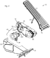
- eine perspektivische Explosionsdarstellung von Funktionselementen der Pedaleinheit aus
Fig. 1 , darunter eine aktive Kassette; - Fig. 3
- eine perspektivische, vergrößerte Ansicht von Funktionselementen der Pedaleinheit aus
Fig. 1 ,Fig. 2 mit der aktiven Kassette; - Fig. 4
- eine perspektivische Explosionsansicht von Teilen der Pedaleinheit aus
Fig. 1-3 ; - Fig. 5
- eine perspektivische Darstellung von Zahnradelementen eines Getriebes der aktiven Kassette;
- Fig. 6a,6b
- eine Draufsicht auf die Zahnradelemente aus
Fig. 5 in verschiedenen Getriebestellungen und - Fig. 7a, 7b
- in perspektivischer Darstellung eine alternative Ausführungsform von Zahnradelementen.
-
Fig. 1 zeigt in perspektivischer Darstellung eine Pedaleinheit 10, mit einem Grundelement 12 und ein daran auslenkbar angebrachtes Pedalelement 14. Im gezeigten Beispiel eines stehenden Pedals ist das Pedalelement 14 als aufrechtstehende, in einem unteren Gelenk 16 schwenkbar am Grundelement 12 befestigte Pedalplatte ausgebildet. In einer alternativen Ausgestaltung (nicht dargestellt) kann das Pedalelement auch in an sich bekannter Weise als hängendes Pedal ausgebildet sein. - Das Grundelement 12 ist zur festen Anbringung im Fußraum eines KFZ vorgesehen. Über einen Steckeranschluss 18 wird die elektrische Verbindung der Kfz-Elektronik zu einem Sensor für die Betätigungsstellung und einem Motor zur Erzeugung einer variablen Gegenkraft, die beide im Folgenden näher beschrieben werden, hergestellt.
- Das Grundelement 12 umfasst im Wesentlichen ein Gehäuse 22, das mit einer Grundplatte 24, die das Scharnier 16 trägt einstückig als Kunststoffteil ausgebildet ist (
Fig. 2 ) und eine darin eingesetzte aktive Kassette 26, die einen Pedalsensor 28 (Fig. 2 ) und einen elektrischen Motor 30 (Fig. 2 ,Fig. 3 ) aufweist. Aufbau und Funktion der aktiven Kassette 26, die zusätzlich auch die benötigte Steuer- und Auswerteelektronik und den Stecker 18 umfasst, wird unten im Detail beschrieben. - Innerhalb des Gehäuses 22 des Grundelements 12 ist ein mit dem Pedalelement 14 über einen Stellhebel 20 gekoppelter Drehhebel 32 mit einer Rückstellfeder 34 angeordnet (
Fig. 2 ). Wie bspw. ausFig. 3 ersichtlich ist der Koppelhebel 20 gelenkig mit dem Drehhebel 32 so verbunden, dass jede Schwenkbewegung des Pedalelements 14 zu einer synchronen Drehbewegung des Drehhebels 32 führt. Somit kann die Betätigungsstellung des Pedalelements 14 mit einem Sensor 28, der die Stellung des Drehhebels 32 abfragt, ermittelt werden. - Durch die Rückstellfeder 34 wird der Drehhebel 32 und damit auch das Pedalelement 14 in eine Grundstellung zurückgestellt, solange keine ausreichende Betätigungskraft wirkt.
- Die Force-Feedback-Funktion der Pedaleinheit 10 wird durch die aktive Kassette 26 erfüllt. Diese umfasst ein Kassettengehäuse, in dem die in
Fig. 3 - 5 dargestellten Funktionselemente angeordnet sind, nämlich ein Elektromotor 30, ein Getriebe 40 und eine Freilauf-Kopplung 42. - Das Getriebe 40 ist dabei innerhalb eines separaten Kassettengehäuses gekapselt und somit gegenüber Verschmutzungen unempfindlich. Wie aus
Fig. 4 ersichtlich ist die aktive Kassette 26 durch einen Deckel 68 abgedeckt. - Der Motor 30 weist auf seiner Motorwelle 38 ein Antriebsritzel 36 auf, das mit dem Getriebe 40 gekoppelt ist. Dabei steht das Ritzel 36 mit einem speziell ausgebildeten Zahnradelement 44 im Eingriff. Ein Koppelelement 50 weist ein spezielles Zahnradelement 52 auf, das als Verzahnungshebel 52 ausgebildet ist, und das an einem Verzahnungsbereich mit dem Zahnradelement 44 in Eingriff steht.
- Das Getriebe 40 ist, wie insbesondere aus
Fig. 4 ersichtlich ist, auf einer Platte 64 aufgebaut, durch die es vom restlichen Innenraum der Pedaleinheit 10 getrennt ist. Insbesondere trennt die Platte 64 den Bereich der Zahnradpaarungen des Getriebes 40 von dem Bereich des Drehhebels 32 mit dem Koppelhebel 20. Da der Koppelhebel 20 durch eine Öffnung des Gehäuses 22 nach Außen ragt, können von dort u.U. Verschmutzungen in das Gehäuse 22 eintreten. Durch die Platte 64 ist sichergestellt, dass die Verschmutzungen nicht ins Getriebe 40 eindringen können, was sich im Betrieb durch deutlich veränderte Bedienungskräfte bemerkbar machen würde. Durch die Kapselung zwischen der Platte 64 und dem Deckel 68 ist das Getriebe 40 vor solchen Einflüssen geschützt. - Innerhalb des Getriebes 40 umfasst das Zahnradelement 44, wie insbesondere aus
Fig. 5 ersichtlich ist, keine einheitliche Verzahnung über seinen gesamten Umfang, sondern einen ersten Verzahnungsbereich 46 und einen zweiten Verzahnungsbereich 48. Der erste Verzahnungsbereich 46 weist dabei einen größeren, im gezeigten Beispiel etwa doppelt so großen Verzahnungsradius auf wie der zweite Verzahnungsbereich 48, ausgehend von der Drehachse 47 des Zahnradelements 44. Beide Verzahnungsbereiche 46, 48 erstrecken sich nur jeweils über einen Teil des Gesamtumfanges, wobei in der gezeigten Ausführung der erste Verzahnungsbereich 46 einen Teilumfang von ca. 190° und der zweite Verzahnungsbereich 48 einen Teilumfang von ca. 210° abdeckt. Dabei weist der erste Verzahnungsbereich ein vorspringendes Ende 49 auf. - Die Verzahnung in den Verzahnungsbereichen 46, 48 weist gleiche Zahnteilung auf, so dass das Zahnradelement 44 innerhalb des Getriebes 40 eine Untersetzungsstufe bildet.
- Dabei liegen die Verzahnungsbereiche 46, 48 in einer Ebene. Wie dargestellt ist somit das gesamte Getriebe 40 in einer Ebene auf einer Tragplatte 64 aufgebaut. Die Tragplatte 64 ist dabei aus Aluminium, so dass einerseits en stabiler Aufbau und andererseits eine gute Wärmeableitung von Verlustärme am Motor 30 ermöglicht werden.
- Der Verzahnungshebel 52 weist ebenfalls einen sich nur über einen Teilumfang von im gezeigten Beispiel ca. 45° erstreckenden Verzahnungsbereich auf. Er ist einstückig ausgebildet mit dem Koppelelement 50, wie insbesondere aus
Fig. 4 ,Fig. 5 ersichtlich ist. - Am Verzahnungshebel 52 ist eine Aufnahme 56 für eine Rückstellfeder 58 (
Fig. 6a, 6b ) vorgesehen. Weiter ist am Verzahnungshebel 52 eine in der gezeigten Ausführung als Tasche 60 ausgebildete Ausnehmung vorgesehen, die eine Eintrittsöffnung in Drehrichtung aufweist. - Das Koppelelement 50 ist Teil der Freilauf-Kopplung 42. Dabei ist die Freilauf-Kopplung 42 wie insbesondere aus
Fig. 2 ,Fig. 3 ersichtlich als Gabelkopplung ausgebildet mit einem ersten Gabelelement 42a auf Seiten des Koppelelements 50 und einem zweiten Gabelelement 42b auf Seiten des Drehhebels 32. Im zusammengefügten Zustand sind die Gabelelemente 42a, 42b verzahnt ineinander angeordnet. Bei Betätigung des Pedalelements 14 und entsprechender Drehung des Drehhebels 32 entgegen der Wirkung der Rückstellfeder 34 dreht sich das zweite Gabelelement 42b inFig. 3 links herum. Dabei kommt es zu einer Mitnahme des ersten Gabelelements 42a durch Anlage von ersten Anlageflächen auf Seiten des Koppelelements 50 an zweiten Anlageflächen auf Seiten des zweiten Gabelelements 42b. - Allerdings sind die Abstände zwischen den Gabelelementen 42a, 42b so bemessen, dass diese Mitnahme nur bei Bewegung des Drehhebels 32 in Betätigungsrichtung erfolgt, nicht aber in umgekehrter Richtung. Wenn sich nämlich der Drehhebel 32 bei nachlassen der Betätigung zurückstellt oder das Koppelelement 50 in Betätigungsrichtung, d. h. in
Fig. 4 links herum gedreht wird, trennen sich die ersten und zweiten Anlageflächen, so dass ein Freilauf zwischen dem Koppelelement 50 und dem Drehhebel 32 entsteht. Hierdurch ist sichergestellt, dass eine Kopplung zwischen dem Koppelelement 50 und dem Drehhebel 32 stets nur entgegen der Betätigungsrichtung erfolgen kann - ein Niederhalten des Pedalelements 14 durch das Koppelelement 50 in einer betätigten Stellung ist ebenso ausgeschlossen wie eine eigenständige Betätigung des Pedalelements 14 durch das Koppelelement 50. - Der Elektromotor 30 ist somit allein dazu vorgesehen, zusätzlich zu dem Widerstand, den die Rückstellfeder 34 entgegen der Betätigung des Pedalelements 14 aufbringt, eine weitere Gegenkraft zu erzeugen. Je nach Ansteuerung des Motors 30 ist diese Gegenkraft einstellbar, d. h. sowohl der Kraftbetrag als auch die Betätigungsstellung, in der sie wirksam wird, ist variabel und durch elektrische Ansteuerung des Motors 30 vorgebbar.
- Bei Betätigung des Pedalelements 14 in Betätigungsrichtung, d. h. beim Herunterdrücken, bewegt sich wie oben erläutert durch die Kopplungswirkung der Freilauf-Kopplung 42 in dieser Richtung das Koppelelement 50 synchron mit dem Drehhebel 32. Diese Drehbewegung wird durch das Getriebe 40 auf die Motorwelle 38 übertragen.
- Innerhalb des Getriebes 40 erfolgt die Übertragung des Drehmoments über den einstückig mit dem Gabelelement 42a ausgebildeten Verzahnungshebel 52 auf den zweiten Verzahnungsbereich 48 des speziell ausgebildeten Zahnradelements 44 und von dessen ersten Verzahnungsbereich 46 auf das Ritzel 36 an der Motorwelle 38.
-
Fig. 6a, 6b zeigt dabei zwei verschiedene Stellungen des Getriebes 40. Dabei entspricht die erste inFig. 6a dargestellte Getriebestellung etwa einer Leerlaufstellung des Pedalelements 14, während die zweite inFig. 6b dargestellte Getriebestellung etwa einer Vollgasposition entspricht, d.h. durch den Hebel 20 ist der Drehhebel 32 dort maximal heruntergedrückt. Der hiermit gekoppelte Verzahnungshebel 52 befindet sich in der ersten Getriebeposition im Bereich seines rechten, in der zweiten Getriebeposition im Bereich seines linken Anschlags. - In der zweiten in
Fig. 6b dargestellten Getriebestellung ist der vorspringende Bereich 49 des ersten Verzahnungsbereiches 46 des Zahnradelements 44 in der Tasche 60 am Verzahnungshebel 52 aufgenommen. So wird bei geringem Bauraum ein noch relativ großer Schwenkbereich ermöglicht. - Die Feder 58 bringt dabei jeweils eine zusätzliche Rückstellkraft auf, die über die Kopplung 42 auch auf das Pedalelement 14 wirkt. Vor allem bewirkt die Feder 58, dass die Zahnradpaarungen jeweils unter Spannung stehen und Zahnflankenspiel so reduziert wird.
- Die Verzahnung ist dabei an beiden Eingriffspaarungen als Schrägverzahnung ausgebildet. Hierdurch wird Spiel verringert und Geräuschbildung vermieden.
- Durch das Getriebe 40 erfolgt dabei eine deutliche Untersetzung der Drehbewegung des Koppelelements 50 von im gezeigten Beispiel ca. 1:20. Durch die Kopplungswirkung der Freilauf-Kopplung 42 ist die Drehung an der Motorwelle 38 in Betätigungsrichtung synchron mit der Drehung des Drehhebels 32.
- Durch die in
Fig. 3-5 dargestellte Konstruktion erfolgt dabei eine Beeinflussung der für die Bewegung in Betätigungsrichtung benötigten Kraft entsprechend der Ansteuerung des Motors 30. Durch entsprechende Bestromung des Motors 30 kann dann eine steuerbare Gegenkraft gegen die "Rückwärtsdrehung" der Motorwelle 38 aufgebracht werden. Die Ansteuerung des Motors 30 wird nach entsprechendem elektrischen Signal am Steckeranschluss 18 durch eine Motorsteuerung 54 vorgegeben. Bei dem Motor 30 handelt es sich um einen BLDC-Motor, d. h. einen bürstenlosen Elektromotor mit einem Permanentmagnet-Rotor und einer Anzahl von im dargestellten Beispiel sechs Feldspulen. Durch entsprechende Ansteuerung seitens der Motorsteuerung 54 erzeugt der Motor 30 ein Drehmoment, das der für die Betätigung notwendigen Drehrichtung der Motorwelle 38 entgegengerichtet ist und so zu einer - je nach Ansteuerung - variablen Gegenkraft gegen die Betätigung führt. - Durch geeignete Ansteuerung des Motors 30 sind verschiedene Kraftverläufe vorgebbar, abhängig von der Betätigungsstellung und/oder auch von der Zeit. Bspw. kann die Gegenkraft durch den Motor 30 in zeitlich variabler Weise so aufgebracht werden, dass sie als Vibration wahrzunehmen ist, z. B. mit einem zeitlich periodisch variierenden Verlauf. Eine andere zeitlich variable Signalisierungsmöglichkeit ist ein "Anklopfen", bei dem pulsförmige Kraftverläufe vorgegeben werden, wobei zwischen den Kraftpulsen für im Vergleich zur kurzen Dauer der Kraftpulse längere Zeitdauern keine Kraft aufgebracht wird.
- Was verschiedene von der Betätigung abhängige Verläufe angeht, so ist bspw. ein ein- oder mehrstufiger Kickdown darstellbar, d. h. eine übertretbare, deutlich spürbare Kraftspitze. Davon kann eine Kraftspitze an einer festen Betätigungsstellung oder variablen Betätigungsstellung im mittleren Bereich der Betätigung erzeugt werden, bspw. um einen Bereich verbrauchsgünstigen Betriebs zu signalisieren. Alternativ kann eine variable Kraftstufe dargestellt werden, wobei der Motor mit einer konstanten Gegenkraft ab einer vorgegebenen Betätigungsstellung zugeschaltet wird. Je nach gewünschtem Zweck der Signalisierung sind so sehr verschiedene Verläufe denkbar.
- Die jeweilige Pedalstellung wird über einen induktiven Sensor 28 am Drehhebel 32 abgefragt. Dabei ist am Drehhebel 32 ein induktives Indexelement, bevorzugt in Form eines Schwingkreises, auch als "Puck" bezeichnet, vorgesehen. Dem gegenüber ist am Gehäuse der aktiven Kassette 26 ein induktiver Spulenschaltkreis 28 mit mindestens einer Sende- und mindestens einer Empfangsspule vorgesehen. Die Stellung des Drehhebels 32 kann dabei durch die variable induktive Überkopplung von der Sende- in die Empfangsspule ermittelt werden. Ein entsprechender Sensor ist bspw. in der
WO 03/038379 - In
Fig. 7a, 7b ist eine zweite Ausführungsform des speziell ausgebildeten Zahnradelements 44' dargestellt, das im Eingriff mit dem Ritzel 36 an der Motorwelle steht. - Während die bevorzugte Ausführung zur Stabilisierung einen Deckel 66 aufweist, wie in
Fig. 7b gezeigt, wird aus der offenen Darstellung inFig. 7a der Aufbau des Zahnradelements 44' ersichtlich. Dieses verfügt über einen ersten Verzahnungsbereich 46, der als Innenverzahnung mit einem großen, ersten Verzahnungsradius ausgebildet ist und über einen zweiten Verzahnungsbereich 48, der als Außenverzahnung mit einem zweiten, erheblich kleineren Verzahnungsradius ausgebildet ist. Die Innenverzahnung 46 ist dabei an einem Rahmenelement befestigt, das mit dem Deckel 66 verschlossen ist. - Der erste Verzahnungsbereich 46 steht dabei im Eingriff mit dem Ritzel 36, während der zweite Verzahnungsbereich 48 mit dem Verzahnungshebel 52 (in
Fig. 7a, 7b nicht dargestellt) in Eingriff steht. - Das Zahnradelement 44' gemäß der alternativen Ausführungsform ersetzt somit das Zahnradelement 44 der vorbeschriebenen Ausführung und sorgt ebenso wie dieses für eine untersetzte Kopplung zwischen dem Ritzel 36 und dem Verzahnungshebel 52, wobei die beiden Verzahnungsbereiche 46, 48 jeweils nur über Teilumfänge vorhanden sind und beide in einer gemeinsamen Ebene liegen.
- Zu der gezeigten Ausführungsform sind verschiedene weitere Abwandlungen möglich. Zum einen kann statt des sechs-poligen BLDC-Motors 30 ebenso ein anderer Motortyp verwendet werden, zum anderen kann das Getriebe 40, dass im vorliegenden Beispiel als zweistufiges Stirnrad-Untersetzungsgetriebe (in der Alternative mit einer Innenverzahnung) ausgebildet ist, für andere Anwendungsfälle auch anders ausgelegt bzw. konstruiert sein. Es kann zusätzlich ein Sensor für die Stellung des Koppelelements 50 vorgesehen sein. Die Feder 58 am Getriebe 40 kann auch am Ritzel 36 angreifen und bspw. als Spiralfeder ausgebildet sein. Schließlich kann die Pedaleinheit 10 alternativ auch als hängende Pedaleinheit aufgebaut sein.
Claims (14)
- Pedaleinheit mit- einem Pedalelement (14), das gegenüber einem Grundelement (12) in einer Betätigungsrichtung auslenkbar ist,- wobei ein Drehelement (32) so mit dem Pedalelement (14) gekoppelt ist, dass es sich bei Auslenkung des Pedalelements (14) dreht,- und wobei ein Elektromotor (30) zur Erzeugung einer Gegenkraft vorgesehen ist,
dadurch gekennzeichnet, dass- das Drehelement (32) über ein Getriebe (40) mit dem Elektromotor (30) gekoppelt ist,- wobei das Getriebe (40) als Zahnradgetriebe ausgebildet ist mit mindestens einem Zahnradelement (44, 44'), das mindestens einen ersten Verzahnungsbereich (46) mit einem ersten Verzahnungsradius und einem zweiten Verzahnungsbereich (48) mit einem zweiten Verzahnungsradius aufweist, wobei der erste und zweite Verzahnungsradius unterschiedlich sind,- wobei sich der erste und der zweite Verzahnungsbereich (46, 48) jeweils nur über einen Teilumfang erstrecken,- und wobei der erste und zweite Verzahnungsbereich (46, 48) in einer Ebene liegen. - Pedaleinheit nach Anspruch 1, bei der- das Getriebe (40) mindestens ein erstes und ein zweites Zahnradelement (44, 52) aufweist, bei denen sich jeweils ein Verzahnungsbereich (46, 48) nur über einen Teilumfang erstreckt.
- Pedaleinheit nach Anspruch 2, bei der- das zweite Zahn radelement (52) eine Ausnehmung (60) aufweist,- wobei in einer Getriebestellung ein Ende (49) des Verzahnungsbereichs des ersten Zahn radelements (44) in der Ausnehmung (60) aufgenommen ist.
- Pedaleinheit nach einem der vorangehenden Ansprüche, bei der- das Getriebe (40) ein Untersetzungsgetriebe ist, so dass eine höhere Drehzahl am Motor (30) in eine geringere Drehzahl am Drehelement (32) umgesetzt wird.
- Pedaleinheit nach einem der vorangehenden Ansprüche, bei der- das Getriebe (40) eine erste Zahnradpaarung zwischen einem Ritzel (36) des Motors (30) und einem ersten Zahnradelement (44, 44'),- und eine zweite Zahnradpaarung zwischen dem ersten Zahnradelement (44, 44') und einem zweiten Zahnradelement (52) aufweist.
- Pedaleinheit nach Anspruch 5, bei der- das zweite Zahnradelement (52) mit dem Drehelement (32) gekoppelt ist.
- Pedaleinheit nach einem der vorangehenden Ansprüche, bei der- mindestens eine Stufe des Getriebes (40) mit einer mindestens teilweise schrägen Verzahnung versehen ist.
- Pedaleinheit nach einem der vorangehenden Ansprüche, bei der- ein Freilauf-Kopplungselement (42) im Kraftfluss zwischen dem Drehelement (32) und dem Motor (30) vorgesehen ist,- wobei das Drehelement (32) mit dem Motor (30) so gekoppelt ist, dass eine Gegenkraft entgegen der Betätigungsrichtung vom Motor (30) auf das Drehelement (32) wirken kann,- und das Drehelement (32) gegenüber dem Motor (30) Freilauf hat, so dass keine Betätigungskraft in Betätigungsrichtung vom Motor (30) auf das Drehelement (32) wirkt.
- Pedaleinheit nach Anspruch 8, bei der- das Freilauf-Kopplungselement (42) auf einer mit dem Drehelement (32) gekoppelten Seite eine Abtriebs-Anlagefläche aufweist und auf einer mit dem Motor (30) gekoppelten Seite eine Antriebs-Anlagefläche,- wobei bei einer Kraftübertragung entgegen der Betätigungsrichtung die Anlageflächen aneinander anliegen.
- Pedaleinheit nach Anspruch 9, bei der- das Freilauf-Kopplungselement (42) mindestens ein Gabelelement aufweist, an dem mindestens eine der Anlageflächen gebildet ist.
- Pedaleinheit nach einem der vorangehenden Ansprüche, bei der- mindestens ein Verzahnungsbereich (46) des Zahnradelements (44') als Innenverzahnung ausgebildet ist.
- Pedaleinheit nach einem der vorangehenden Ansprüche, bei der- mindestens ein Teil des Freilauf-Kopplungselements (42) mit einem Zahnradelement (52) einstückig ausgebildet ist.
- Pedaleinheit nach einem der vorangehenden Ansprüche, bei der- der Elektromotor als BLDC-Motor (30) vorgesehen ist.
- Pedaleinheit nach einem der vorangehenden Ansprüche, bei der- ein Pedalsensor (28) zur Ermittlung der Stellung des Pedalelements (14) am Drehelement (32) vorgesehen ist.
Applications Claiming Priority (2)
| Application Number | Priority Date | Filing Date | Title |
|---|---|---|---|
| DE102012112514.7A DE102012112514B4 (de) | 2012-12-18 | 2012-12-18 | Pedaleinheit für ein KFZ |
| PCT/EP2013/076290 WO2014095537A1 (de) | 2012-12-18 | 2013-12-11 | Pedaleinheit für ein kfz |
Publications (2)
| Publication Number | Publication Date |
|---|---|
| EP2934937A1 EP2934937A1 (de) | 2015-10-28 |
| EP2934937B1 true EP2934937B1 (de) | 2017-09-06 |
Family
ID=49920318
Family Applications (1)
| Application Number | Title | Priority Date | Filing Date |
|---|---|---|---|
| EP13818201.9A Not-in-force EP2934937B1 (de) | 2012-12-18 | 2013-12-11 | Pedaleinheit für ein kfz |
Country Status (3)
| Country | Link |
|---|---|
| EP (1) | EP2934937B1 (de) |
| DE (1) | DE102012112514B4 (de) |
| WO (1) | WO2014095537A1 (de) |
Families Citing this family (7)
| Publication number | Priority date | Publication date | Assignee | Title |
|---|---|---|---|---|
| CN105216621A (zh) * | 2015-10-31 | 2016-01-06 | 洛阳独树格软轴控制器有限公司 | 一种手动挡车辆离合器踏板 |
| CN105216608A (zh) * | 2015-10-31 | 2016-01-06 | 洛阳独树格软轴控制器有限公司 | 一种压簧式电控复合踏板总成 |
| CN105216609A (zh) * | 2015-10-31 | 2016-01-06 | 洛阳独树格软轴控制器有限公司 | 一种电控复合踏板总成 |
| CN105346386A (zh) * | 2015-10-31 | 2016-02-24 | 洛阳独树格软轴控制器有限公司 | 一种手动挡车辆油门辅助控制方法 |
| US10053061B2 (en) * | 2016-08-29 | 2018-08-21 | GM Global Technology Operations LLC | Brake pedal emulator of a brake-by-wire system for a vehicle |
| US11225141B2 (en) | 2018-05-02 | 2022-01-18 | HELLA GmbH & Co. KGaA | Standing pedal for a vehicle |
| WO2023143919A1 (de) * | 2022-01-27 | 2023-08-03 | HELLA GmbH & Co. KGaA | Fahrpedal mit einem drehstellungssensor mit einer sensordrehachse und einem schwenkbaren betätigungselement mit einer betätigungsdrehachse |
Family Cites Families (10)
| Publication number | Priority date | Publication date | Assignee | Title |
|---|---|---|---|---|
| DE8706142U1 (de) * | 1987-04-29 | 1987-06-19 | Süddeutsche Kühlerfabrik Julius Fr. Behr GmbH & Co KG, 7000 Stuttgart | Verstelleinrichtung mit einem Zahnkranzsegment |
| GB0126014D0 (en) | 2001-10-30 | 2001-12-19 | Sensopad Technologies Ltd | Modulated field position sensor |
| EP1444108B1 (de) | 2001-11-05 | 2010-12-29 | Continental Teves AG & Co. oHG | Vorrichtung mit zusätzlicher rückstellkraft am gaspedal in abhängigkeit von der sollwert - abweichung eines fahrzeugparameters |
| JP4217567B2 (ja) * | 2003-09-04 | 2009-02-04 | 豊田鉄工株式会社 | ペダル反力装置 |
| DE102004027610A1 (de) | 2004-06-05 | 2006-01-05 | Ab Elektronik Gmbh | Pedaleinheit und Pedalbaugruppe für Kraftfahrzeug |
| DE102009021585A1 (de) * | 2009-05-15 | 2010-12-02 | Conti Temic Microelectronic Gmbh | Kompaktes Pedalsystem für ein Kraftfahrzeug |
| WO2011141802A1 (en) * | 2010-05-12 | 2011-11-17 | Ksr Technologies Co. | Compact fly-by-wire pedal assembly |
| JP5466086B2 (ja) * | 2010-06-04 | 2014-04-09 | 株式会社ミクニ | アクセルペダル装置 |
| DE102010063409B4 (de) * | 2010-12-17 | 2013-11-28 | Ab Elektronik Gmbh | Fahrpedal mit einstellbarer Betätigungscharakteristik |
| JP2012219909A (ja) * | 2011-04-08 | 2012-11-12 | Denso Corp | 歯車装置、および、それを用いた回転式アクチュエータ |
-
2012
- 2012-12-18 DE DE102012112514.7A patent/DE102012112514B4/de not_active Expired - Fee Related
-
2013
- 2013-12-11 WO PCT/EP2013/076290 patent/WO2014095537A1/de not_active Ceased
- 2013-12-11 EP EP13818201.9A patent/EP2934937B1/de not_active Not-in-force
Non-Patent Citations (1)
| Title |
|---|
| None * |
Also Published As
| Publication number | Publication date |
|---|---|
| EP2934937A1 (de) | 2015-10-28 |
| WO2014095537A1 (de) | 2014-06-26 |
| DE102012112514A1 (de) | 2014-06-18 |
| DE102012112514B4 (de) | 2015-04-02 |
Similar Documents
| Publication | Publication Date | Title |
|---|---|---|
| DE102012112514B4 (de) | Pedaleinheit für ein KFZ | |
| DE19861100B4 (de) | Spindel- oder Schneckenantrieb für Verstelleinrichtungen in Kraftfahrzeugen | |
| AT505126B1 (de) | Klappenantriebssystem | |
| DE19527912C2 (de) | Beidseitig wirkender, manueller Antrieb zur Erzeugung einer Drehbewegung, insbesondere für Kraftfahrzeugsitze | |
| EP0981696B1 (de) | Exzenterzahnradgetriebe | |
| EP1179458B1 (de) | Antrieb einer an einem Fahrzeug vorgesehenen Klappe und Fussgängerschutz an einem Kraftfahrzeug | |
| DE10101363C1 (de) | Parksperrenbetätigungseinrichtung für eine Parksperrenvorrichtung eines Kraftfahrzeuges | |
| EP0807031B1 (de) | Beidseitig wirkender manueller antrieb zur erzeugung einer drehbewegung | |
| DE102011054655A1 (de) | Pedaleinheit für ein KFZ | |
| DE102004027610A1 (de) | Pedaleinheit und Pedalbaugruppe für Kraftfahrzeug | |
| EP2094541A1 (de) | Elektromechanische antriebsvorrichtung zum einsatz in einer heckklappe eines kraftfahrzeugs | |
| DE69619962T2 (de) | Elektrisch gesteuerte drosselklappe mit veränderbarer antriebsübersetzung | |
| DE19861276B4 (de) | Spindel- oder Schneckenantrieb für Verstelleinrichtungen in Kraftfahrzeugen | |
| WO1997007311A1 (de) | Motor-getriebe-antriebseinheit für ein zwischen endstellungen verstellbares teil | |
| DE20106478U1 (de) | Antrieb einer an einem Fahrzeug vorgesehenen Klappe und Fußgängerschutz an einem Kraftfahrzeug | |
| DE102004039057B3 (de) | Untersetzungsgetriebe und dieses verwendende Antriebseinheit | |
| DE10357729A1 (de) | Lenkungsstellantrieb eines "Steer-by-Wire-Systems" | |
| DE60314927T2 (de) | Vorrichtung mit veränderlichem Übersetzungsverhältnis | |
| EP1412628B1 (de) | Antriebseinrichtung | |
| DE202007003713U1 (de) | Vorrichtung zum Verstellen von Sitzelementen | |
| DE102010048601A1 (de) | Eingabevorrichtung mit variablem Betätigungsgefühl | |
| DE19861278C5 (de) | Spindel- oder Schneckenantrieb für Verstelleinrichtungen in Kraftfahrzeugen | |
| EP1238858A2 (de) | Antrieb für den Rückspiegel eines Kraftfahrzeuges | |
| DE102021103622A1 (de) | Dreh-getriebeanordnung zur vergrösserung des hartanschlag-motorweges | |
| EP2117887B1 (de) | Vorrichtung zur ansteuerung eines sperrgliedes |
Legal Events
| Date | Code | Title | Description |
|---|---|---|---|
| PUAI | Public reference made under article 153(3) epc to a published international application that has entered the european phase |
Free format text: ORIGINAL CODE: 0009012 |
|
| 17P | Request for examination filed |
Effective date: 20150708 |
|
| AK | Designated contracting states |
Kind code of ref document: A1 Designated state(s): AL AT BE BG CH CY CZ DE DK EE ES FI FR GB GR HR HU IE IS IT LI LT LU LV MC MK MT NL NO PL PT RO RS SE SI SK SM TR |
|
| AX | Request for extension of the european patent |
Extension state: BA ME |
|
| DAX | Request for extension of the european patent (deleted) | ||
| GRAP | Despatch of communication of intention to grant a patent |
Free format text: ORIGINAL CODE: EPIDOSNIGR1 |
|
| INTG | Intention to grant announced |
Effective date: 20170321 |
|
| GRAS | Grant fee paid |
Free format text: ORIGINAL CODE: EPIDOSNIGR3 |
|
| GRAJ | Information related to disapproval of communication of intention to grant by the applicant or resumption of examination proceedings by the epo deleted |
Free format text: ORIGINAL CODE: EPIDOSDIGR1 |
|
| GRAL | Information related to payment of fee for publishing/printing deleted |
Free format text: ORIGINAL CODE: EPIDOSDIGR3 |
|
| GRAR | Information related to intention to grant a patent recorded |
Free format text: ORIGINAL CODE: EPIDOSNIGR71 |
|
| GRAA | (expected) grant |
Free format text: ORIGINAL CODE: 0009210 |
|
| INTC | Intention to grant announced (deleted) | ||
| INTG | Intention to grant announced |
Effective date: 20170727 |
|
| AK | Designated contracting states |
Kind code of ref document: B1 Designated state(s): AL AT BE BG CH CY CZ DE DK EE ES FI FR GB GR HR HU IE IS IT LI LT LU LV MC MK MT NL NO PL PT RO RS SE SI SK SM TR |
|
| REG | Reference to a national code |
Ref country code: GB Ref legal event code: FG4D Free format text: NOT ENGLISH |
|
| REG | Reference to a national code |
Ref country code: CH Ref legal event code: EP Ref country code: AT Ref legal event code: REF Ref document number: 925469 Country of ref document: AT Kind code of ref document: T Effective date: 20170915 |
|
| REG | Reference to a national code |
Ref country code: IE Ref legal event code: FG4D Free format text: LANGUAGE OF EP DOCUMENT: GERMAN |
|
| REG | Reference to a national code |
Ref country code: DE Ref legal event code: R096 Ref document number: 502013008310 Country of ref document: DE |
|
| REG | Reference to a national code |
Ref country code: FR Ref legal event code: PLFP Year of fee payment: 5 |
|
| REG | Reference to a national code |
Ref country code: SE Ref legal event code: TRGR |
|
| REG | Reference to a national code |
Ref country code: NL Ref legal event code: MP Effective date: 20170906 |
|
| REG | Reference to a national code |
Ref country code: LT Ref legal event code: MG4D |
|
| PG25 | Lapsed in a contracting state [announced via postgrant information from national office to epo] |
Ref country code: HR Free format text: LAPSE BECAUSE OF FAILURE TO SUBMIT A TRANSLATION OF THE DESCRIPTION OR TO PAY THE FEE WITHIN THE PRESCRIBED TIME-LIMIT Effective date: 20170906 Ref country code: LT Free format text: LAPSE BECAUSE OF FAILURE TO SUBMIT A TRANSLATION OF THE DESCRIPTION OR TO PAY THE FEE WITHIN THE PRESCRIBED TIME-LIMIT Effective date: 20170906 Ref country code: FI Free format text: LAPSE BECAUSE OF FAILURE TO SUBMIT A TRANSLATION OF THE DESCRIPTION OR TO PAY THE FEE WITHIN THE PRESCRIBED TIME-LIMIT Effective date: 20170906 Ref country code: NO Free format text: LAPSE BECAUSE OF FAILURE TO SUBMIT A TRANSLATION OF THE DESCRIPTION OR TO PAY THE FEE WITHIN THE PRESCRIBED TIME-LIMIT Effective date: 20171206 |
|
| PGFP | Annual fee paid to national office [announced via postgrant information from national office to epo] |
Ref country code: FR Payment date: 20171219 Year of fee payment: 5 |
|
| PG25 | Lapsed in a contracting state [announced via postgrant information from national office to epo] |
Ref country code: BG Free format text: LAPSE BECAUSE OF FAILURE TO SUBMIT A TRANSLATION OF THE DESCRIPTION OR TO PAY THE FEE WITHIN THE PRESCRIBED TIME-LIMIT Effective date: 20171206 Ref country code: RS Free format text: LAPSE BECAUSE OF FAILURE TO SUBMIT A TRANSLATION OF THE DESCRIPTION OR TO PAY THE FEE WITHIN THE PRESCRIBED TIME-LIMIT Effective date: 20170906 Ref country code: GR Free format text: LAPSE BECAUSE OF FAILURE TO SUBMIT A TRANSLATION OF THE DESCRIPTION OR TO PAY THE FEE WITHIN THE PRESCRIBED TIME-LIMIT Effective date: 20171207 Ref country code: ES Free format text: LAPSE BECAUSE OF FAILURE TO SUBMIT A TRANSLATION OF THE DESCRIPTION OR TO PAY THE FEE WITHIN THE PRESCRIBED TIME-LIMIT Effective date: 20170906 Ref country code: LV Free format text: LAPSE BECAUSE OF FAILURE TO SUBMIT A TRANSLATION OF THE DESCRIPTION OR TO PAY THE FEE WITHIN THE PRESCRIBED TIME-LIMIT Effective date: 20170906 |
|
| PGFP | Annual fee paid to national office [announced via postgrant information from national office to epo] |
Ref country code: SE Payment date: 20171221 Year of fee payment: 5 Ref country code: IT Payment date: 20171129 Year of fee payment: 5 Ref country code: GB Payment date: 20171221 Year of fee payment: 5 |
|
| PG25 | Lapsed in a contracting state [announced via postgrant information from national office to epo] |
Ref country code: NL Free format text: LAPSE BECAUSE OF FAILURE TO SUBMIT A TRANSLATION OF THE DESCRIPTION OR TO PAY THE FEE WITHIN THE PRESCRIBED TIME-LIMIT Effective date: 20170906 |
|
| PG25 | Lapsed in a contracting state [announced via postgrant information from national office to epo] |
Ref country code: PL Free format text: LAPSE BECAUSE OF FAILURE TO SUBMIT A TRANSLATION OF THE DESCRIPTION OR TO PAY THE FEE WITHIN THE PRESCRIBED TIME-LIMIT Effective date: 20170906 Ref country code: RO Free format text: LAPSE BECAUSE OF FAILURE TO SUBMIT A TRANSLATION OF THE DESCRIPTION OR TO PAY THE FEE WITHIN THE PRESCRIBED TIME-LIMIT Effective date: 20170906 Ref country code: CZ Free format text: LAPSE BECAUSE OF FAILURE TO SUBMIT A TRANSLATION OF THE DESCRIPTION OR TO PAY THE FEE WITHIN THE PRESCRIBED TIME-LIMIT Effective date: 20170906 |
|
| PG25 | Lapsed in a contracting state [announced via postgrant information from national office to epo] |
Ref country code: EE Free format text: LAPSE BECAUSE OF FAILURE TO SUBMIT A TRANSLATION OF THE DESCRIPTION OR TO PAY THE FEE WITHIN THE PRESCRIBED TIME-LIMIT Effective date: 20170906 Ref country code: SK Free format text: LAPSE BECAUSE OF FAILURE TO SUBMIT A TRANSLATION OF THE DESCRIPTION OR TO PAY THE FEE WITHIN THE PRESCRIBED TIME-LIMIT Effective date: 20170906 Ref country code: SM Free format text: LAPSE BECAUSE OF FAILURE TO SUBMIT A TRANSLATION OF THE DESCRIPTION OR TO PAY THE FEE WITHIN THE PRESCRIBED TIME-LIMIT Effective date: 20170906 Ref country code: IS Free format text: LAPSE BECAUSE OF FAILURE TO SUBMIT A TRANSLATION OF THE DESCRIPTION OR TO PAY THE FEE WITHIN THE PRESCRIBED TIME-LIMIT Effective date: 20180106 |
|
| REG | Reference to a national code |
Ref country code: DE Ref legal event code: R097 Ref document number: 502013008310 Country of ref document: DE |
|
| PLBE | No opposition filed within time limit |
Free format text: ORIGINAL CODE: 0009261 |
|
| STAA | Information on the status of an ep patent application or granted ep patent |
Free format text: STATUS: NO OPPOSITION FILED WITHIN TIME LIMIT |
|
| PG25 | Lapsed in a contracting state [announced via postgrant information from national office to epo] |
Ref country code: DK Free format text: LAPSE BECAUSE OF FAILURE TO SUBMIT A TRANSLATION OF THE DESCRIPTION OR TO PAY THE FEE WITHIN THE PRESCRIBED TIME-LIMIT Effective date: 20170906 |
|
| REG | Reference to a national code |
Ref country code: CH Ref legal event code: PL |
|
| 26N | No opposition filed |
Effective date: 20180607 |
|
| PG25 | Lapsed in a contracting state [announced via postgrant information from national office to epo] |
Ref country code: SI Free format text: LAPSE BECAUSE OF FAILURE TO SUBMIT A TRANSLATION OF THE DESCRIPTION OR TO PAY THE FEE WITHIN THE PRESCRIBED TIME-LIMIT Effective date: 20170906 |
|
| REG | Reference to a national code |
Ref country code: IE Ref legal event code: MM4A |
|
| PG25 | Lapsed in a contracting state [announced via postgrant information from national office to epo] |
Ref country code: MT Free format text: LAPSE BECAUSE OF FAILURE TO SUBMIT A TRANSLATION OF THE DESCRIPTION OR TO PAY THE FEE WITHIN THE PRESCRIBED TIME-LIMIT Effective date: 20170906 Ref country code: LU Free format text: LAPSE BECAUSE OF NON-PAYMENT OF DUE FEES Effective date: 20171211 |
|
| REG | Reference to a national code |
Ref country code: BE Ref legal event code: MM Effective date: 20171231 |
|
| PG25 | Lapsed in a contracting state [announced via postgrant information from national office to epo] |
Ref country code: IE Free format text: LAPSE BECAUSE OF NON-PAYMENT OF DUE FEES Effective date: 20171211 |
|
| PG25 | Lapsed in a contracting state [announced via postgrant information from national office to epo] |
Ref country code: BE Free format text: LAPSE BECAUSE OF NON-PAYMENT OF DUE FEES Effective date: 20171231 Ref country code: CH Free format text: LAPSE BECAUSE OF NON-PAYMENT OF DUE FEES Effective date: 20171231 Ref country code: LI Free format text: LAPSE BECAUSE OF NON-PAYMENT OF DUE FEES Effective date: 20171231 |
|
| RIC2 | Information provided on ipc code assigned after grant |
Ipc: F16H 19/00 20060101ALI20140709BHEP Ipc: B60K 26/02 20060101AFI20140709BHEP Ipc: G05G 1/44 20080401ALI20140709BHEP Ipc: G05G 5/03 20080401ALI20140709BHEP |
|
| PG25 | Lapsed in a contracting state [announced via postgrant information from national office to epo] |
Ref country code: HU Free format text: LAPSE BECAUSE OF FAILURE TO SUBMIT A TRANSLATION OF THE DESCRIPTION OR TO PAY THE FEE WITHIN THE PRESCRIBED TIME-LIMIT; INVALID AB INITIO Effective date: 20131211 Ref country code: MC Free format text: LAPSE BECAUSE OF FAILURE TO SUBMIT A TRANSLATION OF THE DESCRIPTION OR TO PAY THE FEE WITHIN THE PRESCRIBED TIME-LIMIT Effective date: 20170906 |
|
| REG | Reference to a national code |
Ref country code: SE Ref legal event code: EUG |
|
| PG25 | Lapsed in a contracting state [announced via postgrant information from national office to epo] |
Ref country code: SE Free format text: LAPSE BECAUSE OF NON-PAYMENT OF DUE FEES Effective date: 20181212 |
|
| GBPC | Gb: european patent ceased through non-payment of renewal fee |
Effective date: 20181211 |
|
| PG25 | Lapsed in a contracting state [announced via postgrant information from national office to epo] |
Ref country code: IT Free format text: LAPSE BECAUSE OF NON-PAYMENT OF DUE FEES Effective date: 20181211 Ref country code: CY Free format text: LAPSE BECAUSE OF FAILURE TO SUBMIT A TRANSLATION OF THE DESCRIPTION OR TO PAY THE FEE WITHIN THE PRESCRIBED TIME-LIMIT Effective date: 20170906 |
|
| PG25 | Lapsed in a contracting state [announced via postgrant information from national office to epo] |
Ref country code: MK Free format text: LAPSE BECAUSE OF FAILURE TO SUBMIT A TRANSLATION OF THE DESCRIPTION OR TO PAY THE FEE WITHIN THE PRESCRIBED TIME-LIMIT Effective date: 20170906 |
|
| PG25 | Lapsed in a contracting state [announced via postgrant information from national office to epo] |
Ref country code: GB Free format text: LAPSE BECAUSE OF NON-PAYMENT OF DUE FEES Effective date: 20181211 |
|
| PGFP | Annual fee paid to national office [announced via postgrant information from national office to epo] |
Ref country code: DE Payment date: 20191114 Year of fee payment: 7 |
|
| REG | Reference to a national code |
Ref country code: AT Ref legal event code: MM01 Ref document number: 925469 Country of ref document: AT Kind code of ref document: T Effective date: 20181211 |
|
| PG25 | Lapsed in a contracting state [announced via postgrant information from national office to epo] |
Ref country code: FR Free format text: LAPSE BECAUSE OF NON-PAYMENT OF DUE FEES Effective date: 20181231 |
|
| PG25 | Lapsed in a contracting state [announced via postgrant information from national office to epo] |
Ref country code: TR Free format text: LAPSE BECAUSE OF FAILURE TO SUBMIT A TRANSLATION OF THE DESCRIPTION OR TO PAY THE FEE WITHIN THE PRESCRIBED TIME-LIMIT Effective date: 20170906 |
|
| PG25 | Lapsed in a contracting state [announced via postgrant information from national office to epo] |
Ref country code: AT Free format text: LAPSE BECAUSE OF NON-PAYMENT OF DUE FEES Effective date: 20181211 |
|
| PG25 | Lapsed in a contracting state [announced via postgrant information from national office to epo] |
Ref country code: PT Free format text: LAPSE BECAUSE OF FAILURE TO SUBMIT A TRANSLATION OF THE DESCRIPTION OR TO PAY THE FEE WITHIN THE PRESCRIBED TIME-LIMIT Effective date: 20170906 |
|
| PG25 | Lapsed in a contracting state [announced via postgrant information from national office to epo] |
Ref country code: AL Free format text: LAPSE BECAUSE OF FAILURE TO SUBMIT A TRANSLATION OF THE DESCRIPTION OR TO PAY THE FEE WITHIN THE PRESCRIBED TIME-LIMIT Effective date: 20170906 |
|
| REG | Reference to a national code |
Ref country code: DE Ref legal event code: R119 Ref document number: 502013008310 Country of ref document: DE |
|
| PG25 | Lapsed in a contracting state [announced via postgrant information from national office to epo] |
Ref country code: DE Free format text: LAPSE BECAUSE OF NON-PAYMENT OF DUE FEES Effective date: 20210701 |