EP2934358B1 - Magnetische aktivierung von monopolaren und bipolaren vorrichtungen - Google Patents
Magnetische aktivierung von monopolaren und bipolaren vorrichtungen Download PDFInfo
- Publication number
- EP2934358B1 EP2934358B1 EP13818906.3A EP13818906A EP2934358B1 EP 2934358 B1 EP2934358 B1 EP 2934358B1 EP 13818906 A EP13818906 A EP 13818906A EP 2934358 B1 EP2934358 B1 EP 2934358B1
- Authority
- EP
- European Patent Office
- Prior art keywords
- magnetic
- cord
- housing
- wire
- connection
- Prior art date
- Legal status (The legal status is an assumption and is not a legal conclusion. Google has not performed a legal analysis and makes no representation as to the accuracy of the status listed.)
- Active
Links
Images




Classifications
-
- A—HUMAN NECESSITIES
- A61—MEDICAL OR VETERINARY SCIENCE; HYGIENE
- A61B—DIAGNOSIS; SURGERY; IDENTIFICATION
- A61B18/00—Surgical instruments, devices or methods for transferring non-mechanical forms of energy to or from the body
- A61B18/18—Surgical instruments, devices or methods for transferring non-mechanical forms of energy to or from the body by applying electromagnetic radiation, e.g. microwaves
-
- A—HUMAN NECESSITIES
- A61—MEDICAL OR VETERINARY SCIENCE; HYGIENE
- A61B—DIAGNOSIS; SURGERY; IDENTIFICATION
- A61B18/00—Surgical instruments, devices or methods for transferring non-mechanical forms of energy to or from the body
- A61B18/04—Surgical instruments, devices or methods for transferring non-mechanical forms of energy to or from the body by heating
- A61B18/12—Surgical instruments, devices or methods for transferring non-mechanical forms of energy to or from the body by heating by passing a current through the tissue to be heated, e.g. high-frequency current
- A61B18/14—Probes or electrodes therefor
- A61B18/1492—Probes or electrodes therefor having a flexible, catheter-like structure, e.g. for heart ablation
-
- H—ELECTRICITY
- H01—ELECTRIC ELEMENTS
- H01R—ELECTRICALLY-CONDUCTIVE CONNECTIONS; STRUCTURAL ASSOCIATIONS OF A PLURALITY OF MUTUALLY-INSULATED ELECTRICAL CONNECTING ELEMENTS; COUPLING DEVICES; CURRENT COLLECTORS
- H01R11/00—Individual connecting elements providing two or more spaced connecting locations for conductive members which are, or may be, thereby interconnected, e.g. end pieces for wires or cables supported by the wire or cable and having means for facilitating electrical connection to some other wire, terminal, or conductive member, blocks of binding posts
- H01R11/11—End pieces or tapping pieces for wires, supported by the wire and for facilitating electrical connection to some other wire, terminal or conductive member
- H01R11/30—End pieces held in contact by a magnet
-
- A—HUMAN NECESSITIES
- A61—MEDICAL OR VETERINARY SCIENCE; HYGIENE
- A61B—DIAGNOSIS; SURGERY; IDENTIFICATION
- A61B18/00—Surgical instruments, devices or methods for transferring non-mechanical forms of energy to or from the body
- A61B2018/00053—Mechanical features of the instrument of device
- A61B2018/00172—Connectors and adapters therefor
- A61B2018/00178—Electrical connectors
-
- A—HUMAN NECESSITIES
- A61—MEDICAL OR VETERINARY SCIENCE; HYGIENE
- A61B—DIAGNOSIS; SURGERY; IDENTIFICATION
- A61B18/00—Surgical instruments, devices or methods for transferring non-mechanical forms of energy to or from the body
- A61B2018/00315—Surgical instruments, devices or methods for transferring non-mechanical forms of energy to or from the body for treatment of particular body parts
- A61B2018/00529—Liver
- A61B2018/00535—Biliary tract
-
- A—HUMAN NECESSITIES
- A61—MEDICAL OR VETERINARY SCIENCE; HYGIENE
- A61B—DIAGNOSIS; SURGERY; IDENTIFICATION
- A61B18/00—Surgical instruments, devices or methods for transferring non-mechanical forms of energy to or from the body
- A61B2018/00315—Surgical instruments, devices or methods for transferring non-mechanical forms of energy to or from the body for treatment of particular body parts
- A61B2018/00553—Sphincter
-
- A—HUMAN NECESSITIES
- A61—MEDICAL OR VETERINARY SCIENCE; HYGIENE
- A61B—DIAGNOSIS; SURGERY; IDENTIFICATION
- A61B18/00—Surgical instruments, devices or methods for transferring non-mechanical forms of energy to or from the body
- A61B2018/00571—Surgical instruments, devices or methods for transferring non-mechanical forms of energy to or from the body for achieving a particular surgical effect
- A61B2018/00601—Cutting
-
- A—HUMAN NECESSITIES
- A61—MEDICAL OR VETERINARY SCIENCE; HYGIENE
- A61B—DIAGNOSIS; SURGERY; IDENTIFICATION
- A61B18/00—Surgical instruments, devices or methods for transferring non-mechanical forms of energy to or from the body
- A61B18/04—Surgical instruments, devices or methods for transferring non-mechanical forms of energy to or from the body by heating
- A61B18/12—Surgical instruments, devices or methods for transferring non-mechanical forms of energy to or from the body by heating by passing a current through the tissue to be heated, e.g. high-frequency current
- A61B18/14—Probes or electrodes therefor
- A61B2018/1405—Electrodes having a specific shape
- A61B2018/144—Wire
-
- H—ELECTRICITY
- H01—ELECTRIC ELEMENTS
- H01R—ELECTRICALLY-CONDUCTIVE CONNECTIONS; STRUCTURAL ASSOCIATIONS OF A PLURALITY OF MUTUALLY-INSULATED ELECTRICAL CONNECTING ELEMENTS; COUPLING DEVICES; CURRENT COLLECTORS
- H01R2201/00—Connectors or connections adapted for particular applications
- H01R2201/12—Connectors or connections adapted for particular applications for medicine and surgery
Definitions
- the present embodiments relate generally to a system for providing electrosurgery using electrosurgical devices and, more particularly, to an electrosurgical device having a magnetic connection for transmitting power to the electrosurgical device from a power source.
- electrosurgical devices to perform medical procedures on a patient is common in the medical field.
- One type of electrosurgical device is a sphincterotome.
- Sphincterotomes are commonly used to incise or cut a sphincter of a patient.
- a sphincter is a generally circular muscle that generally maintains constriction of a natural body passage or orifice.
- a surgeon can operate a sphincterotome to cannulate various ductal systems that include sphincters, such as the biliary duct.
- Common sphincterotomes includes structure for navigating through the patient's body to a location where cannulation of the sphincter is desired.
- the sphincterotome includes a cutting wire that is exposed at the distal end of the device.
- the cutting wire can be energized to provide heat to the wire for cutting and cauterizing the surgical area for cannulation.
- common sphincterotomes are electrically connected to a power source for providing the electrical energy to the cutting wire.
- Sphincterotomes can be either monopolar or bipolar.
- a monopolar device the active electrical path is provided by the device, with the patient's body providing the return path through an electrosurgical pad or other known method.
- a bipolar device the return path is carried back through the device via a return wire. Both monopolar and bipolar devices are common in the art and require no further discussion.
- the electrical wires receiving and providing power are connected to a power source for providing power to the device.
- the power source is generally a separate component from the device, where various devices or device types can be attached thereto.
- the electrosurgical device requires a connection to the power source.
- connection to the power source is in the form of a universal pin.
- the universal pin can be disposed either on the device or from the power source.
- the pin is received in a corresponding receptacle at either the device or the power source.
- This pin and receptacle connection is generally maintained through friction, snap fit, or other mechanical type connection.
- this type of connection is susceptible to breaking in the event that a force is applied transverse to the axis of the connection, which can be costly to repair or replace in the event that the pin is broken.
- Banana plugs can be used to connect wires with a pin-shaped receptacle similar to the above.
- installing the banana plug to the wires can be time consuming, and similarly suffers from the risk of breaking as described above.
- replacement of the banana plug can be costly and time consuming during a medical procedure.
- connection can be in the form of a coaxial cable connection.
- Coaxial connections are known in the art, where one end of a wire can be mechanically coupled to a corresponding receptacle. This connection can withstand forces applied thereto generally better than a pin-style connection, but suffers from the inability to become unseated in the event of a sufficient force acting against it, which can lead to damage to the electrosurgical device or connected power source if it does not become un-coupled.
- bipolar connections With respect to bipolar connections, the above described connections generally require two connections: one for the active wire and another for the receiving wire. Connecting two wires can require additional time to make the connections relative to a single connection.
- a monopolar device generally requires only the single active wire to be connected to the power source. However, the monopolar device requires the additional use of an electrical pad connected to the patient to provide the return path.
- Sphincterotomes are generally single use devices, being disposed of after use by the surgeon.
- a connection between the sphincterotome and the power source that is easy to attach, while likewise being easy to detach in the event of a force applied to it that limits damage to the connection.
- a cord for transferring electrical power and signals can be provided to connect a first device to a second device.
- One or more magnetic couplings can be provided to exert magnetic forces between the cord and the first device and/or between the cord and the second device. The one or more magnetic couplings can allow transfer of electrical power and signals therethrough.
- a system for providing an electrical current during surgery comprising: an elongate electrosurgical device having a distal end and proximal end and a longitudinal device axis extending therebetween; a conductive cutting wire mounted to the device and extending along the longitudinal axis, the conductive cutting wire having an exposed cutting portion at the distal end; a device housing at the proximal end of the device, the device housing at least partially covering the conductive cutting wire mounted therein; an elongate cord having proximal and distal ends and a longitudinal cord axis therebetween with an active wire therein for transferring power from a power source; a cord housing at the distal end of the elongate cord, the cord housing covering at least a portion of the active wire; a magnetic connection between the device housing and the cord housing, the magnetic connection comprising both a mechanical and electrical connection; a recess of the magnetic connection extending generally transverse to the longitudinal axes of the device housing and the cord housing
- system further comprises a device return wire extending along the electrosurgical device and a power source return wire extending along the power cord.
- system further comprises a second recess and a second magnetic post, and wherein the second recess includes a second recessed magnetic surface, and the device return wire and power source return wire are coupled via a magnetic connection between the second magnetic post and the second recessed magnetic surface.
- the electrosurgical device is a sphincterotome.
- the electrosurgical device includes a handle portion, the handle portion includes an actuating ring, and the actuating ring is a portion of the device housing.
- the conductive cutting wire includes a curved portion extending around a portion of the actuating ring.
- the device housing includes a stepped portion
- the cord housing includes a head portion
- the head portion is received in the stepped portion
- the head portion and stepped portion have a generally racetrack shape.
- the conductive cutting wire terminates at the distal end of the electrosurgical device.
- the device return wire is coupled to a conductive portion disposed at the distal end of the electrosurgical device.
- the device housing includes the recess and the cord housing includes the magnetic post.
- the magnetic post and the recess have a generally cylindrical shape.
- a method for connecting an electrosurgical device to a power source comprising: providing an electrosurgical device having a proximal end and a distal end, a longitudinal axis extending therebetween, and a conductive cutting wire extending generally along the longitudinal axis; wherein the device includes a housing at the proximal end and the housing includes a recess therein having an axis that is generally transverse to the longitudinal axis of the device, and the recess includes a recessed magnetic surface; wherein the recessed magnetic surface is electrically connected to the conductive cutting wire; providing a power cord having an active wire extending along a longitudinal axis of the cord; wherein the power cord includes a cord housing at a distal end thereof; wherein the cord housing includes a magnetic post extending therefrom generally transverse to the to the longitudinal axis of the cord; aligning the axes of the magnetic post and the recess; aligning the longitudinal axes of the device housing and the cord housing; inserting the
- the axes of the magnetic post and the recess are aligned coaxially.
- the cord housing includes two magnetic posts and the device housing includes two recesses, and the two magnetic posts are inserted into the two recesses.
- the cord housing includes a head portion
- the device housing includes a stepped portion sized for receiving the head portion
- the method further comprises the step of inserting the head portion into the stepped portion.
- the device in another form, includes a return wire therein, the power cord includes a return wire therein, and the return wires are electrically connected through a connection between one of the magnetic posts and one of the recessed surfaces.
- an elongate electrosurgical device comprising: a tubular body having a proximal and distal end and a longitudinal axis therebetween; a handle portion coupled to the proximal end of the tubular body, the handle portion having a longitudinal axis therealong; a housing of the handle portion at a proximal end thereof; a recess extending into the housing, the recess having an axis that is generally perpendicular to the longitudinal axis of the handle portion; a recessed magnetic surface disposed within the recess; a cutting wire electrically connected to the recessed magnetic surface and extending through the handle portion and the tubular body to the distal end thereof; and wherein the recess is sized to receive a magnetic post having a shape corresponding to the recess for electrically connecting the cutting wire to an active wire electrically connected to the magnetic post.
- the housing includes a stepped portion therein sized to receive a head portion of a cord housing having the magnetic post extending therefrom.
- the device further comprises; a second recess having a second recessed magnetic surface therein; a conductive return wire electrically connected to the second recessed magnetic surface and extending within the handle portion and the tubular body to the distal end thereof; and wherein the conductive return wire is electrically connected to the cutting wire.
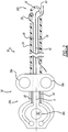
- FIG. 1 illustrates an electrosurgical system 10 including an electrosurgical device 12, a power source 14, and an electrical cord or power cord 16 connecting the device 12 and the power source 14.
- the electrosurgical device 12 is in the form of a sphincterotome 18.
- the electrical cord or power cord 16 can generally include a proximal end 16a that is connected to the power source 14 and a distal end 16b that is connected to the sphincterotome 18.
- the cord 16 can be connected to the sphincterotome 18 via an electromechanical connection 20.
- the electromechanical connection 20 can be in the form of a magnetic connection 22, which will be further described below.
- the sphincterotome 18 includes a tubular body 24 having a proximal end 24a and a distal end 24b.
- the tubular body 24 includes a cutting wire 26 extending therethrough, where a cutting portion 28 of the cutting wire 26 extends outside of the tubular body 24 at the distal end 24b.
- the tubular body 24 can also include a guidewire 30 extending therealong, with the guidewire 30 extending outside of the tubular body 24 at the distal end 24b.
- the tubular body 24 can also include a cutting wire lumen (not shown) and a guidewire lumen (not shown) through which the cutting wire 26 and guidewire 30 extend, respectively. It will be appreciated that Figure 2 is a schematic representation, and the cutting wire 26 and guidewire 30 do not generally share a common lumen.
- the sphincterotome 18 can also include a distal tip 36 at the distal end 24b of the tubular body 24 that can be manipulated and bent by actuating a handle portion 38 disposed at the proximal end 24a as is known in the art.
- the handle portion 38 includes a pair of gripping rings 38a that assist in gripping the handle portion 38, as well as an actuating ring 38b that is coupled to the cutting wire 26.
- Actuating the handle portion 38 includes pulling on the actuating ring 38b, which puts the cutting wire 26 in tension in a manner known in the art.
- Putting the cutting wire 26 in tension will cause the distal tip 36 to bend and arc, where the cutting portion 28 of the cutting wire will form a secant with the arced distal tip 36.
- the cutting portion 28 of the cutting wire 26 can then cut and cauterize tissue at the adjacent anatomical area, as is known in the art, to cannulate a sphincter.
- the handle portion 38 has a generally longitudinal length with a longitudinal axis A that can generally correspond to the longitudinal axis of the tubular body 24 of the sphincterotome 18.
- the handle portion 38 includes one half of the electromechanical connection 20 between the sphincterotome 18 and the power source cord 16, which will be described in further detail below.
- the power source 14 can be a standard power source 14 for use in electrosurgical procedures such as sphincterotomy or the like.
- the power source 14 can be configured to supply an electrical current to the sphincterotome 18, wherein the resistive properties of the cutting wire 26 will result in the cutting wire 26 becoming heated, as is known in the art, to cut and cauterize adjacent tissue.
- the power cord 16 can extend from the power source 14 for connection to the device 12 via the electromechanical connection 20.
- the power cord 16 can be integral with the power source 14, or can be coupled to the power source 14 via a typical plug-in type connection (not shown) or the like, as is known in the art.
- the power cord 16 is generally flexible in nature, and includes an active wire 40 extending therethrough and insulated via known wire insulation methods.
- the active wire 40 carries the current from the power source 14 to the cutting wire 26 via the electromechanical connection 20 with the sphincterotome 18.
- the power cord 16 includes a proximal end 16a, which is connected the power source 14, a distal end 16b, and a longitudinal axis B extending therebetween.
- the distal end 16b comprises one half of the electromechanical connection 20 for coupling with the other half of the connection 20 of the sphincterotome 18, further described below.
- the sphincterotome 18 can include a return wire 42 and the power cord 16 can include a return wire 44 for completing the electrical circuit in a bipolar configuration.
- the return wire 42 can be coupled to a conductive portion 43 disposed at the distal tip 36 in a manner known in the art and shown schematically in Figure 2 .
- the sphincterotome 18 and power cord 16 will include the cutting wire 26 and the active wire 40, respectively, but no return wire.
- the circuit is completed through the patient via an electrical pad or connection connected thereon and further connected to a negative terminal of the power source 14, or to a ground.
- FIG. 2 is a schematic representation, and the return wire 42 will generally extend through a dedicated lumen (not shown) and will not share a common lumen with the cutting wire 26 and the guidewire 30.
- the electromechanical connection 20 can be in the form of the magnetic connection 22 and can include a first housing or device housing 50 coupled to the handle portion 38 of the sphincterotome 18 and a second housing or power cord housing 80 coupled to the distal end 16b of the power cord 16.
- the device housing 50 and power cord housing 80 can be coupled together via cooperating structure discussed in further detail below.
- the device housing 50 can include a device housing body 54 having a proximal end 54a.
- the body 54 can have a generally two-piece configuration comprising a base member 56 and a lid member 58.
- the base member 56 and lid member 58 can have generally similar outer profiles, so that when they are mated together via a mechanical or adhesive connection, the base member 56 and lid member 58 will combine to create the housing body 54.
- the device housing 50 can comprise the actuating ring 38b of the handle portion 38 with an actuating ring hole 60 extending through the device housing 50.
- the base member 56 can include at least one recessed channel 62 extending in a generally longitudinal direction from the proximal end 54a of the housing body 54 and along the handle portion 38 of the sphincterotome 18.
- the channel 62 can have a curved shape to account for the shape of the device housing 50 and handle portion 38.
- the channel 62 can extend about the hole 60 of the device housing 50 when the housing 50 comprises the actuating ring 38b of the handle portion 38.
- the cutting wire 26 can be disposed within the channel 62 so that it will run from the distal tip 36 to the proximal end 54a of the housing body 54.
- the cutting wire 26 can include a flat ribbon shaped curved portion 64, where the curved portion 64 extends about the hole 60.
- the proximal end 54a of the housing body 54 can include a generally cylindrical shaped opening or recess 70 having an axis R that is generally transverse and perpendicular to the longitudinal axis A of the device 12 and the handle portion 38.
- the recess 70 can include a recessed magnetic mating surface 72 therein.
- the magnetic mating surface 72 is electrically connected to the cutting wire 26 by way of soldering or other known methods.
- the magnetic mating surface 72 can have properties sufficient for being magnetically coupled to a corresponding magnet having the opposite polarity.
- the magnetic mating surface 72 can also have properties sufficient for transmitting an electric current therethrough, so that when coupled to a corresponding electrically conductive magnet, the magnetic surface 72 will transfer the current to the cutting wire 26.
- the device housing 50 can include a second recess 74 and a second recessed magnetic surface 76 having a configuration similar to the recess 70 and mating surface 72.
- the second recessed surface 76 will carry the current of the return path from the return wire 42.
- the housing 50 can also include a stepped portion 78.
- the stepped portion 78 can be flat and shaped to mate with a corresponding portion of a power cord housing 80, which will be further described below.
- the stepped portion 78 can have a generally "racetrack" shape.
- the power cord housing 80 can be disposed at the distal end 16b of the power cord 16 that extends from the power source 14.
- the power cord housing 80 can include a cord housing body 82.
- the cord housing 80 can also include a magnetic post 86 having a generally cylindrical shape that corresponds to the cylindrical shape of the recess 70 in the device housing 50.
- the magnetic post 86 has an axis P that is generally transverse and perpendicular to the longitudinal axis B of the power cord 16 and the cord housing 80.
- the housing body 82 can include a head portion 88 at the distal end thereof.
- the head portion 88 can have a shape corresponding to the stepped portion 78 of the device housing 50.
- the head portion 88 can have a generally "racetrack” shape so that the head portion 88 can become seated onto the stepped portion 78 of the device housing 50.
- the magnetic post 86 extends from the head portion 88, so that when the head portion 88 is received on the stepped portion 78 of the device housing 50, the magnetic post 86 can be received in the recess 70 of the device housing 50.
- the magnetic connection 22 can withstand a separation force applied thereto that is below a predetermined threshold level, while becoming disconnected in response to a separation force that is greater than the threshold level.
- the magnetic connection 22 will also transmit an electrical current therethough, so that that a current from the power source 14 through the power cord 16 will be passed on to the sphincterotome 18.
- the cord housing 80 can include a second magnetic post 90 similar to the magnetic post 86 described above. Rather than provide the active current, the second magnetic post 90 will provide the connection for the return path in a manner known in the art.
- the sphincterotome 18 is generally a single use device 12, such that the device 12 can be discarded after use.
- a new sphincterotome 18 can be provided for connection to the system 10 and the power source 14.
- the surgeon can simply locate the device housing 50 having the recess 70 and the recessed magnetic surface 72.
- the device housing 50 is integral with the handle portion 38, where the device housing 50 includes the actuating ring 38b of the handle portion 38. In this form, the surgeon can locate the device housing 50 by locating the proximal end of the handle portion 38.
- the power source 14 having the power cord 16 can be provided for connection to the sphincterotome 18.
- the surgeon can locate the power cord 16 and the distal end 16b thereof, which includes the cord housing 80.
- the surgeon can locate the head portion 88 of the cord housing 80, which includes the magnetic posts 86 and 90 described above.
- the surgeon can manipulate the head portion 88 to align the magnetic posts 86 and 90 with the recesses 70 and 74 in the device housing 50.
- the surgeon can next insert the magnetic posts 86 and 90 into the recesses 70 and 74 of the device housing 50.
- the magnetic properties of the magnetic posts 86 and 90 and the recessed magnetic surfaces 72 and 76 will operate to magnetically couple the posts 86 and 90 and recessed surfaces 72 and 76, thereby creating the magnetic connection 22 between the device housing 50 and the cord housing 80.
- the head portion 88 With the insertion of the magnetic posts 86 and 90, the head portion 88 is also inserted into the device housing 50 at the stepped portion 78, so that the head portion 88 is received therein.
- the coupling of the head portion 88 and the stepped portion 78 creates a mechanical connection in the longitudinal direction corresponding to the power cord 16 and the sphincterotome 18.
- the surgeon can create a longitudinal mechanical connection that can withstand a longitudinal force exerted thereon by way of pushing or pulling on the cord 16 or sphincterotome 18.
- the magnetic connection 22 being aligned transverse to the longitudinal direction, creates a connection that can withstand a force acting in a direction transverse to the longitudinal axis of the sphincterotome 18 and the power cord 16.
- the axes R and P can be generally coaxially aligned with each other, with the axes A and B being generally parallel, where axes R and P are generally perpendicular to axes A and B.
- the magnetic connection that is arranged to withstand a transverse force is also arranged to become de-coupled in the event of a sufficient transverse force.
- the connection can become de-coupled, allowing the cord 16 to fall away from the sphincterotome 18 while limiting trauma to the patient caused by the inadvertent contact.
- This is in contrast to a longitudinally aligned pin-type connection, where a transverse force could result in the sphincterotome 18 becoming misaligned or torqued within the patient's body, or in the pin breaking, resulting in costly repair or replacement.
- connection 22 becomes de-coupled, the surgeon can simply re-locate the cord 16 and make the connection 22 again.
- the magnetic nature of the connection 22 allows for a fast and easy manner of connecting the sphincterotome 18 to the power cord 16 repeatedly, if necessary.
- the surgeon can simply grasp the connection 22 and de-couple the magnetic connection 22, removing the head portion 88 of the cord housing 80 from the stepped portion 78 of the device housing 50, thereby removing the magnetic posts 86 and 90 from the recesses 70 and 74.
- the use of the sphincterotome 18 to perform cannulation of various sphincters within the body has been referred to generally above. Additional detail regarding the use of the sphincterotome 18 can be found in United States Patent Application Publication No. 2009/0043259, filed August 8, 2007 and published February 12, 2009. Further detail regarding the use and structure of the bipolar configuration of the sphincterotome 18 can be found in United States Patent No. 5,035,696, filed February 2, 1990 and issued July 30, 1991.
- the device housing 50 having the recesses 70 and 74
- the cord housing 80 having the magnetic posts 86 and 90 for being received in the recesses 70 and 74
- the opposite configuration could also be used, where the device housing 50 includes the posts 86 and 90 and the power cord 16 includes the recesses 70 and 74.
Landscapes
- Health & Medical Sciences (AREA)
- Surgery (AREA)
- Life Sciences & Earth Sciences (AREA)
- Engineering & Computer Science (AREA)
- Biomedical Technology (AREA)
- Molecular Biology (AREA)
- Nuclear Medicine, Radiotherapy & Molecular Imaging (AREA)
- Veterinary Medicine (AREA)
- Physics & Mathematics (AREA)
- Heart & Thoracic Surgery (AREA)
- Medical Informatics (AREA)
- Otolaryngology (AREA)
- Animal Behavior & Ethology (AREA)
- General Health & Medical Sciences (AREA)
- Public Health (AREA)
- Cardiology (AREA)
- Plasma & Fusion (AREA)
- Electromagnetism (AREA)
- Surgical Instruments (AREA)
Claims (14)
- System zum Bereitstellen eines elektrischen Stroms während einer chirurgischen Behandlung, das System Folgendes umfassend:eine längliche elektrochirurgische Vorrichtung (12), die Folgendes aufweistein Distalende und ein Proximalende und eine longitudinale Vorrichtungsachse, die sich dazwischen erstreckt;einen Griffabschnitt (38), der an dem Proximalende angeordnet ist und einen Betätigungsring (38b) mit einer Betätigungsringöffnung (60) umfasst;einen leitfähigen Schneiddraht (26), der an der Vorrichtung angebracht ist und sich entlang der Längsachse erstreckt, wobei der leitfähige Schneiddraht einen freiliegenden Schneidabschnitt an dem Distalende aufweist;ein Vorrichtungsgehäuse (50), das den leitfähigen Schneiddraht, der darin angebracht ist, mindestens teilweise abdeckt;ein längliches Kabel (16), das Folgendes aufweistdadurch gekennzeichnet, dassein Proximal- und ein Distalende und eine longitudinale Kabelachse dazwischen mit einem aktiven Draht darin zum Übertragen von Strom aus einer Stromquelle;ein Kabelgehäuse (80) an dem Distalende des länglichen Kabels, wobei das Kabelgehäuse mindestens einen Abschnitt des aktiven Drahts abdeckt; undeine Verbindung zwischen dem Vorrichtungsgehäuse und dem Kabelgehäuse, wobei die Verbindung eine elektrische Verbindung umfasst;
die Verbindung zwischen dem Vorrichtungsgehäuse und dem Kabelgehäuse eine magnetische Verbindung umfasst, die sowohl ein mechanische als auch eine elektrische Verbindung umfasst;
das Vorrichtungsgehäuse den Betätigungsring umfasst;
eine Vertiefung (70) der magnetischen Verbindung, die sich im Allgemeinen transversal zu den longitudinalen Achsen des Vorrichtungsgehäuses und des Kabelgehäuses erstreckt, wobei die Vertiefung eine vertiefte magnetische Oberfläche umfasst;
ein magnetischer Stift (86) der magnetischen Verbindung, die sich im Allgemeinen transversal zu den longitudinalen Achsen des Vorrichtungsgehäuses und des Kabelgehäuses erstreckt und bemessen ist, der Gestalt der Vertiefung zu entsprechen;
wobei die magnetische Oberfläche entweder mit dem leitfähigen Draht oder mit dem aktiven Draht elektrisch verbunden ist;
wobei der magnetische Stift mit dem anderen des leitfähigen Drahts oder des aktiven Drahts elektrisch verbunden ist;
wobei der magnetische Stift die magnetische Oberfläche kontaktiert und zum Übertragen von Strom aus dem aktiven Draht an den leitfähigen Draht magnetisch und elektrisch daran angeschlossen ist; und
wobei der magnetische Stift in der Vertiefung senkrecht zu den longitudinalen Achsen des Vorrichtungsgehäuses und des Kabelgehäuses aufgenommen wird. - System nach Anspruch 1, weiterhin umfassend einen Nullleiterdraht der Vorrichtung, der sich entlang der elektrochirurgischen Vorrichtung erstreckt, und einen Nullleiterdraht der Stromquelle, der sich entlang des Stromkabels erstreckt.
- System nach Anspruch 2, weiterhin umfassend eine zweite Vertiefung und einen zweiten magnetischen Stift, und wobei die zweite Vertiefung eine zweite vertiefte magnetische Oberfläche umfasst und der Nullleiterdraht der Vorrichtung und der Nullleiterdraht der Stromquelle über eine magnetische Verbindung zwischen dem zweiten magnetischen Stift und der zweiten vertieften magnetischen Oberfläche verbunden sind.
- System nach einem der vorhergehenden Ansprüche, wobei die elektrochirurgische Vorrichtung eine Sphinkterotomie-Vorrichtung ist.
- System nach einem der vorhergehenden Ansprüche, wobei der leitfähige Schneiddraht einen gekrümmten Abschnitt umfasst, der sich um einen Abschnitt des Betätigungsrings herum erstreckt.
- System nach einem der vorhergehenden Ansprüche, wobei das Vorrichtungsgehäuse einen gestuften Abschnitt umfasst, das Kabelgehäuse einen Kopfabschnitt umfasst und der gestufte Abschnitt bemessen ist, den Kopfabschnitt aufzunehmen.
- System nach Anspruch 6, wobei der Kopfabschnitt und der gestufte Abschnitt derartig konfiguriert sind, dass die Koppelung des Kopfabschnitts und des gestuften Abschnitts eine mechanische Verbindung in der Längsrichtung entsprechend dem Stromkabel und der elektrochirurgischen Vorrichtung erzeugt, wobei die mechanische Verbindung einer longitudinalen Kraft widersteht, die darauf ausgeübt wird.
- System nach einem der vorhergehenden Ansprüche, wobei der leitfähige Schneiddraht an dem Distalende der elektrochirurgischen Vorrichtung terminiert ist.
- System nach Anspruch 8, wobei der Nullleiterdraht der Vorrichtung an einen leitfähigen Abschnitt angeschlossen ist, der an dem Distalende der elektrochirurgischen Vorrichtung angeordnet ist.
- System nach einem der vorhergehenden Ansprüche, wobei das Vorrichtungsgehäuse die Vertiefung umfasst und das Kabelgehäuse den magnetischen Stift umfasst.
- System nach einem der vorhergehenden Ansprüche, wobei der magnetische Stift und die Vertiefung eine im Allgemeinen zylindrische Gestalt aufweisen.
- System nach einem der vorhergehenden Ansprüche, wobei das Kabelgehäuse zwei magnetische Stifte umfasst und das Vorrichtungsgehäuse zwei Vertiefungen umfasst und die beiden magnetischen Stifte bemessen und konfiguriert sind, von den beiden Vertiefungen aufgenommen zu werden.
- Verfahren zum Verbinden einer elektrochirurgischen Vorrichtung eines Systems nach einem der Ansprüche 1 bis 12 mit einer Stromquelle, das Verfahren Folgendes umfassend:Versehen der elektrochirurgischen Vorrichtung mit dem leitfähigen Schneiddraht und dem Vorrichtungsgehäuse;Bereitstellen des länglichen Kabels, das den aktiven Draht aufweist, und des Kabelgehäuses;Ausrichten der Achsen des magnetischen Stifts und der Vertiefung;Ausrichten der longitudinalen Achsen des Vorrichtungsgehäuses und des Kabelgehäuses;Einführen des magnetischen Stifts in die Vertiefung;Kontaktieren des magnetischen Stifts mit der vertieften magnetischen Oberfläche, um die magnetische Verbindung dazwischen zu vervollständigen.
- Verfahren nach Anspruch 13, wobei die Achsen des magnetischen Stifts und der Vertiefung koaxial ausgerichtet sind.
Applications Claiming Priority (2)
| Application Number | Priority Date | Filing Date | Title |
|---|---|---|---|
| US13/722,520 US9468498B2 (en) | 2012-12-20 | 2012-12-20 | Magnetic activation of monopolar and bipolar devices |
| PCT/US2013/076071 WO2014100149A1 (en) | 2012-12-20 | 2013-12-18 | Magnetic activation of monopolar and bipolar devices |
Publications (2)
| Publication Number | Publication Date |
|---|---|
| EP2934358A1 EP2934358A1 (de) | 2015-10-28 |
| EP2934358B1 true EP2934358B1 (de) | 2019-04-03 |
Family
ID=49943541
Family Applications (1)
| Application Number | Title | Priority Date | Filing Date |
|---|---|---|---|
| EP13818906.3A Active EP2934358B1 (de) | 2012-12-20 | 2013-12-18 | Magnetische aktivierung von monopolaren und bipolaren vorrichtungen |
Country Status (3)
| Country | Link |
|---|---|
| US (1) | US9468498B2 (de) |
| EP (1) | EP2934358B1 (de) |
| WO (1) | WO2014100149A1 (de) |
Families Citing this family (138)
| Publication number | Priority date | Publication date | Assignee | Title |
|---|---|---|---|---|
| US11229472B2 (en) | 2001-06-12 | 2022-01-25 | Cilag Gmbh International | Modular battery powered handheld surgical instrument with multiple magnetic position sensors |
| US8182501B2 (en) | 2004-02-27 | 2012-05-22 | Ethicon Endo-Surgery, Inc. | Ultrasonic surgical shears and method for sealing a blood vessel using same |
| JP5009159B2 (ja) | 2004-10-08 | 2012-08-22 | エシコン・エンド−サージェリィ・インコーポレイテッド | 超音波手術器具 |
| US20070191713A1 (en) | 2005-10-14 | 2007-08-16 | Eichmann Stephen E | Ultrasonic device for cutting and coagulating |
| US7621930B2 (en) | 2006-01-20 | 2009-11-24 | Ethicon Endo-Surgery, Inc. | Ultrasound medical instrument having a medical ultrasonic blade |
| US8142461B2 (en) | 2007-03-22 | 2012-03-27 | Ethicon Endo-Surgery, Inc. | Surgical instruments |
| US8226675B2 (en) | 2007-03-22 | 2012-07-24 | Ethicon Endo-Surgery, Inc. | Surgical instruments |
| US8911460B2 (en) | 2007-03-22 | 2014-12-16 | Ethicon Endo-Surgery, Inc. | Ultrasonic surgical instruments |
| US8057498B2 (en) | 2007-11-30 | 2011-11-15 | Ethicon Endo-Surgery, Inc. | Ultrasonic surgical instrument blades |
| US8523889B2 (en) | 2007-07-27 | 2013-09-03 | Ethicon Endo-Surgery, Inc. | Ultrasonic end effectors with increased active length |
| US8808319B2 (en) | 2007-07-27 | 2014-08-19 | Ethicon Endo-Surgery, Inc. | Surgical instruments |
| US8882791B2 (en) | 2007-07-27 | 2014-11-11 | Ethicon Endo-Surgery, Inc. | Ultrasonic surgical instruments |
| US9044261B2 (en) | 2007-07-31 | 2015-06-02 | Ethicon Endo-Surgery, Inc. | Temperature controlled ultrasonic surgical instruments |
| US8512365B2 (en) | 2007-07-31 | 2013-08-20 | Ethicon Endo-Surgery, Inc. | Surgical instruments |
| US8430898B2 (en) | 2007-07-31 | 2013-04-30 | Ethicon Endo-Surgery, Inc. | Ultrasonic surgical instruments |
| CN101883531B (zh) | 2007-10-05 | 2014-07-02 | 伊西康内外科公司 | 人体工程学外科手术器械 |
| US10010339B2 (en) | 2007-11-30 | 2018-07-03 | Ethicon Llc | Ultrasonic surgical blades |
| US9089360B2 (en) | 2008-08-06 | 2015-07-28 | Ethicon Endo-Surgery, Inc. | Devices and techniques for cutting and coagulating tissue |
| US9700339B2 (en) | 2009-05-20 | 2017-07-11 | Ethicon Endo-Surgery, Inc. | Coupling arrangements and methods for attaching tools to ultrasonic surgical instruments |
| US8344596B2 (en) | 2009-06-24 | 2013-01-01 | Ethicon Endo-Surgery, Inc. | Transducer arrangements for ultrasonic surgical instruments |
| US8663220B2 (en) | 2009-07-15 | 2014-03-04 | Ethicon Endo-Surgery, Inc. | Ultrasonic surgical instruments |
| USRE47996E1 (en) | 2009-10-09 | 2020-05-19 | Ethicon Llc | Surgical generator for ultrasonic and electrosurgical devices |
| US11090104B2 (en) | 2009-10-09 | 2021-08-17 | Cilag Gmbh International | Surgical generator for ultrasonic and electrosurgical devices |
| US9168054B2 (en) | 2009-10-09 | 2015-10-27 | Ethicon Endo-Surgery, Inc. | Surgical generator for ultrasonic and electrosurgical devices |
| US10441345B2 (en) | 2009-10-09 | 2019-10-15 | Ethicon Llc | Surgical generator for ultrasonic and electrosurgical devices |
| US9060775B2 (en) | 2009-10-09 | 2015-06-23 | Ethicon Endo-Surgery, Inc. | Surgical generator for ultrasonic and electrosurgical devices |
| US8579928B2 (en) | 2010-02-11 | 2013-11-12 | Ethicon Endo-Surgery, Inc. | Outer sheath and blade arrangements for ultrasonic surgical instruments |
| US8486096B2 (en) | 2010-02-11 | 2013-07-16 | Ethicon Endo-Surgery, Inc. | Dual purpose surgical instrument for cutting and coagulating tissue |
| US8469981B2 (en) | 2010-02-11 | 2013-06-25 | Ethicon Endo-Surgery, Inc. | Rotatable cutting implement arrangements for ultrasonic surgical instruments |
| US8961547B2 (en) | 2010-02-11 | 2015-02-24 | Ethicon Endo-Surgery, Inc. | Ultrasonic surgical instruments with moving cutting implement |
| US8951272B2 (en) | 2010-02-11 | 2015-02-10 | Ethicon Endo-Surgery, Inc. | Seal arrangements for ultrasonically powered surgical instruments |
| GB2480498A (en) | 2010-05-21 | 2011-11-23 | Ethicon Endo Surgery Inc | Medical device comprising RF circuitry |
| US8795327B2 (en) | 2010-07-22 | 2014-08-05 | Ethicon Endo-Surgery, Inc. | Electrosurgical instrument with separate closure and cutting members |
| US9192431B2 (en) | 2010-07-23 | 2015-11-24 | Ethicon Endo-Surgery, Inc. | Electrosurgical cutting and sealing instrument |
| US9259265B2 (en) | 2011-07-22 | 2016-02-16 | Ethicon Endo-Surgery, Llc | Surgical instruments for tensioning tissue |
| WO2013119545A1 (en) | 2012-02-10 | 2013-08-15 | Ethicon-Endo Surgery, Inc. | Robotically controlled surgical instrument |
| US9724118B2 (en) | 2012-04-09 | 2017-08-08 | Ethicon Endo-Surgery, Llc | Techniques for cutting and coagulating tissue for ultrasonic surgical instruments |
| US9241731B2 (en) | 2012-04-09 | 2016-01-26 | Ethicon Endo-Surgery, Inc. | Rotatable electrical connection for ultrasonic surgical instruments |
| US9237921B2 (en) | 2012-04-09 | 2016-01-19 | Ethicon Endo-Surgery, Inc. | Devices and techniques for cutting and coagulating tissue |
| US9226766B2 (en) | 2012-04-09 | 2016-01-05 | Ethicon Endo-Surgery, Inc. | Serial communication protocol for medical device |
| US9439668B2 (en) | 2012-04-09 | 2016-09-13 | Ethicon Endo-Surgery, Llc | Switch arrangements for ultrasonic surgical instruments |
| US20140005705A1 (en) | 2012-06-29 | 2014-01-02 | Ethicon Endo-Surgery, Inc. | Surgical instruments with articulating shafts |
| US9351754B2 (en) | 2012-06-29 | 2016-05-31 | Ethicon Endo-Surgery, Llc | Ultrasonic surgical instruments with distally positioned jaw assemblies |
| US9326788B2 (en) | 2012-06-29 | 2016-05-03 | Ethicon Endo-Surgery, Llc | Lockout mechanism for use with robotic electrosurgical device |
| US9283045B2 (en) | 2012-06-29 | 2016-03-15 | Ethicon Endo-Surgery, Llc | Surgical instruments with fluid management system |
| US20140005702A1 (en) | 2012-06-29 | 2014-01-02 | Ethicon Endo-Surgery, Inc. | Ultrasonic surgical instruments with distally positioned transducers |
| US9198714B2 (en) | 2012-06-29 | 2015-12-01 | Ethicon Endo-Surgery, Inc. | Haptic feedback devices for surgical robot |
| US9393037B2 (en) | 2012-06-29 | 2016-07-19 | Ethicon Endo-Surgery, Llc | Surgical instruments with articulating shafts |
| US9820768B2 (en) | 2012-06-29 | 2017-11-21 | Ethicon Llc | Ultrasonic surgical instruments with control mechanisms |
| US9408622B2 (en) | 2012-06-29 | 2016-08-09 | Ethicon Endo-Surgery, Llc | Surgical instruments with articulating shafts |
| US9226767B2 (en) | 2012-06-29 | 2016-01-05 | Ethicon Endo-Surgery, Inc. | Closed feedback control for electrosurgical device |
| WO2014052181A1 (en) | 2012-09-28 | 2014-04-03 | Ethicon Endo-Surgery, Inc. | Multi-function bi-polar forceps |
| US10201365B2 (en) | 2012-10-22 | 2019-02-12 | Ethicon Llc | Surgeon feedback sensing and display methods |
| US9095367B2 (en) | 2012-10-22 | 2015-08-04 | Ethicon Endo-Surgery, Inc. | Flexible harmonic waveguides/blades for surgical instruments |
| US20140135804A1 (en) | 2012-11-15 | 2014-05-15 | Ethicon Endo-Surgery, Inc. | Ultrasonic and electrosurgical devices |
| WO2014158513A1 (en) * | 2013-03-13 | 2014-10-02 | Cook Medical Technologies Llc | Rotation mechanism for bipolar and monopolar devices |
| US10226273B2 (en) | 2013-03-14 | 2019-03-12 | Ethicon Llc | Mechanical fasteners for use with surgical energy devices |
| US9241728B2 (en) | 2013-03-15 | 2016-01-26 | Ethicon Endo-Surgery, Inc. | Surgical instrument with multiple clamping mechanisms |
| US9814514B2 (en) | 2013-09-13 | 2017-11-14 | Ethicon Llc | Electrosurgical (RF) medical instruments for cutting and coagulating tissue |
| US20150094713A1 (en) * | 2013-09-30 | 2015-04-02 | Covidien Lp | Systems and methods for electrical coupling in a medical device |
| US9265926B2 (en) | 2013-11-08 | 2016-02-23 | Ethicon Endo-Surgery, Llc | Electrosurgical devices |
| GB2521228A (en) | 2013-12-16 | 2015-06-17 | Ethicon Endo Surgery Inc | Medical device |
| GB2521229A (en) | 2013-12-16 | 2015-06-17 | Ethicon Endo Surgery Inc | Medical device |
| US9795436B2 (en) | 2014-01-07 | 2017-10-24 | Ethicon Llc | Harvesting energy from a surgical generator |
| US9554854B2 (en) | 2014-03-18 | 2017-01-31 | Ethicon Endo-Surgery, Llc | Detecting short circuits in electrosurgical medical devices |
| US10092310B2 (en) | 2014-03-27 | 2018-10-09 | Ethicon Llc | Electrosurgical devices |
| US10463421B2 (en) | 2014-03-27 | 2019-11-05 | Ethicon Llc | Two stage trigger, clamp and cut bipolar vessel sealer |
| US9737355B2 (en) | 2014-03-31 | 2017-08-22 | Ethicon Llc | Controlling impedance rise in electrosurgical medical devices |
| US9913680B2 (en) | 2014-04-15 | 2018-03-13 | Ethicon Llc | Software algorithms for electrosurgical instruments |
| US10285724B2 (en) | 2014-07-31 | 2019-05-14 | Ethicon Llc | Actuation mechanisms and load adjustment assemblies for surgical instruments |
| US10639092B2 (en) | 2014-12-08 | 2020-05-05 | Ethicon Llc | Electrode configurations for surgical instruments |
| US10245095B2 (en) | 2015-02-06 | 2019-04-02 | Ethicon Llc | Electrosurgical instrument with rotation and articulation mechanisms |
| US10321950B2 (en) | 2015-03-17 | 2019-06-18 | Ethicon Llc | Managing tissue treatment |
| US10342602B2 (en) | 2015-03-17 | 2019-07-09 | Ethicon Llc | Managing tissue treatment |
| US10595929B2 (en) | 2015-03-24 | 2020-03-24 | Ethicon Llc | Surgical instruments with firing system overload protection mechanisms |
| US10034684B2 (en) | 2015-06-15 | 2018-07-31 | Ethicon Llc | Apparatus and method for dissecting and coagulating tissue |
| US11020140B2 (en) | 2015-06-17 | 2021-06-01 | Cilag Gmbh International | Ultrasonic surgical blade for use with ultrasonic surgical instruments |
| US11129669B2 (en) | 2015-06-30 | 2021-09-28 | Cilag Gmbh International | Surgical system with user adaptable techniques based on tissue type |
| US10898256B2 (en) | 2015-06-30 | 2021-01-26 | Ethicon Llc | Surgical system with user adaptable techniques based on tissue impedance |
| US10765470B2 (en) | 2015-06-30 | 2020-09-08 | Ethicon Llc | Surgical system with user adaptable techniques employing simultaneous energy modalities based on tissue parameters |
| US10357303B2 (en) | 2015-06-30 | 2019-07-23 | Ethicon Llc | Translatable outer tube for sealing using shielded lap chole dissector |
| US10034704B2 (en) | 2015-06-30 | 2018-07-31 | Ethicon Llc | Surgical instrument with user adaptable algorithms |
| US11051873B2 (en) | 2015-06-30 | 2021-07-06 | Cilag Gmbh International | Surgical system with user adaptable techniques employing multiple energy modalities based on tissue parameters |
| US10154852B2 (en) | 2015-07-01 | 2018-12-18 | Ethicon Llc | Ultrasonic surgical blade with improved cutting and coagulation features |
| US20170086909A1 (en) | 2015-09-30 | 2017-03-30 | Ethicon Endo-Surgery, Llc | Frequency agile generator for a surgical instrument |
| US10595930B2 (en) | 2015-10-16 | 2020-03-24 | Ethicon Llc | Electrode wiping surgical device |
| US10179022B2 (en) | 2015-12-30 | 2019-01-15 | Ethicon Llc | Jaw position impedance limiter for electrosurgical instrument |
| US10575892B2 (en) | 2015-12-31 | 2020-03-03 | Ethicon Llc | Adapter for electrical surgical instruments |
| US11134978B2 (en) | 2016-01-15 | 2021-10-05 | Cilag Gmbh International | Modular battery powered handheld surgical instrument with self-diagnosing control switches for reusable handle assembly |
| US12193698B2 (en) | 2016-01-15 | 2025-01-14 | Cilag Gmbh International | Method for self-diagnosing operation of a control switch in a surgical instrument system |
| US11129670B2 (en) | 2016-01-15 | 2021-09-28 | Cilag Gmbh International | Modular battery powered handheld surgical instrument with selective application of energy based on button displacement, intensity, or local tissue characterization |
| US10716615B2 (en) | 2016-01-15 | 2020-07-21 | Ethicon Llc | Modular battery powered handheld surgical instrument with curved end effectors having asymmetric engagement between jaw and blade |
| US11229471B2 (en) | 2016-01-15 | 2022-01-25 | Cilag Gmbh International | Modular battery powered handheld surgical instrument with selective application of energy based on tissue characterization |
| US10555769B2 (en) | 2016-02-22 | 2020-02-11 | Ethicon Llc | Flexible circuits for electrosurgical instrument |
| US10485607B2 (en) | 2016-04-29 | 2019-11-26 | Ethicon Llc | Jaw structure with distal closure for electrosurgical instruments |
| US10702329B2 (en) | 2016-04-29 | 2020-07-07 | Ethicon Llc | Jaw structure with distal post for electrosurgical instruments |
| US10646269B2 (en) | 2016-04-29 | 2020-05-12 | Ethicon Llc | Non-linear jaw gap for electrosurgical instruments |
| US10456193B2 (en) | 2016-05-03 | 2019-10-29 | Ethicon Llc | Medical device with a bilateral jaw configuration for nerve stimulation |
| US10245064B2 (en) | 2016-07-12 | 2019-04-02 | Ethicon Llc | Ultrasonic surgical instrument with piezoelectric central lumen transducer |
| US10893883B2 (en) | 2016-07-13 | 2021-01-19 | Ethicon Llc | Ultrasonic assembly for use with ultrasonic surgical instruments |
| US10842522B2 (en) | 2016-07-15 | 2020-11-24 | Ethicon Llc | Ultrasonic surgical instruments having offset blades |
| US10376305B2 (en) | 2016-08-05 | 2019-08-13 | Ethicon Llc | Methods and systems for advanced harmonic energy |
| US10285723B2 (en) | 2016-08-09 | 2019-05-14 | Ethicon Llc | Ultrasonic surgical blade with improved heel portion |
| USD847990S1 (en) | 2016-08-16 | 2019-05-07 | Ethicon Llc | Surgical instrument |
| US10828056B2 (en) | 2016-08-25 | 2020-11-10 | Ethicon Llc | Ultrasonic transducer to waveguide acoustic coupling, connections, and configurations |
| US10952759B2 (en) | 2016-08-25 | 2021-03-23 | Ethicon Llc | Tissue loading of a surgical instrument |
| US10603064B2 (en) | 2016-11-28 | 2020-03-31 | Ethicon Llc | Ultrasonic transducer |
| US11266430B2 (en) | 2016-11-29 | 2022-03-08 | Cilag Gmbh International | End effector control and calibration |
| WO2018156639A1 (en) | 2017-02-21 | 2018-08-30 | Microvention, Inc. | Electrical catheter |
| US10820920B2 (en) | 2017-07-05 | 2020-11-03 | Ethicon Llc | Reusable ultrasonic medical devices and methods of their use |
| US12076006B2 (en) | 2019-12-30 | 2024-09-03 | Cilag Gmbh International | Surgical instrument comprising an orientation detection system |
| US11696776B2 (en) | 2019-12-30 | 2023-07-11 | Cilag Gmbh International | Articulatable surgical instrument |
| US12336747B2 (en) | 2019-12-30 | 2025-06-24 | Cilag Gmbh International | Method of operating a combination ultrasonic / bipolar RF surgical device with a combination energy modality end-effector |
| US12053224B2 (en) | 2019-12-30 | 2024-08-06 | Cilag Gmbh International | Variation in electrode parameters and deflectable electrode to modify energy density and tissue interaction |
| US12023086B2 (en) | 2019-12-30 | 2024-07-02 | Cilag Gmbh International | Electrosurgical instrument for delivering blended energy modalities to tissue |
| US11452525B2 (en) | 2019-12-30 | 2022-09-27 | Cilag Gmbh International | Surgical instrument comprising an adjustment system |
| US11986234B2 (en) | 2019-12-30 | 2024-05-21 | Cilag Gmbh International | Surgical system communication pathways |
| US11937863B2 (en) | 2019-12-30 | 2024-03-26 | Cilag Gmbh International | Deflectable electrode with variable compression bias along the length of the deflectable electrode |
| US11786291B2 (en) | 2019-12-30 | 2023-10-17 | Cilag Gmbh International | Deflectable support of RF energy electrode with respect to opposing ultrasonic blade |
| US11950797B2 (en) | 2019-12-30 | 2024-04-09 | Cilag Gmbh International | Deflectable electrode with higher distal bias relative to proximal bias |
| US12262937B2 (en) | 2019-12-30 | 2025-04-01 | Cilag Gmbh International | User interface for surgical instrument with combination energy modality end-effector |
| US11779387B2 (en) | 2019-12-30 | 2023-10-10 | Cilag Gmbh International | Clamp arm jaw to minimize tissue sticking and improve tissue control |
| US12082808B2 (en) | 2019-12-30 | 2024-09-10 | Cilag Gmbh International | Surgical instrument comprising a control system responsive to software configurations |
| US12064109B2 (en) | 2019-12-30 | 2024-08-20 | Cilag Gmbh International | Surgical instrument comprising a feedback control circuit |
| US12349961B2 (en) | 2019-12-30 | 2025-07-08 | Cilag Gmbh International | Electrosurgical instrument with electrodes operable in bipolar and monopolar modes |
| US11707318B2 (en) | 2019-12-30 | 2023-07-25 | Cilag Gmbh International | Surgical instrument with jaw alignment features |
| US12114912B2 (en) | 2019-12-30 | 2024-10-15 | Cilag Gmbh International | Non-biased deflectable electrode to minimize contact between ultrasonic blade and electrode |
| US11779329B2 (en) | 2019-12-30 | 2023-10-10 | Cilag Gmbh International | Surgical instrument comprising a flex circuit including a sensor system |
| US12343063B2 (en) | 2019-12-30 | 2025-07-01 | Cilag Gmbh International | Multi-layer clamp arm pad for enhanced versatility and performance of a surgical device |
| US20210196361A1 (en) | 2019-12-30 | 2021-07-01 | Ethicon Llc | Electrosurgical instrument with monopolar and bipolar energy capabilities |
| US11660089B2 (en) | 2019-12-30 | 2023-05-30 | Cilag Gmbh International | Surgical instrument comprising a sensing system |
| US11986201B2 (en) | 2019-12-30 | 2024-05-21 | Cilag Gmbh International | Method for operating a surgical instrument |
| US11944366B2 (en) | 2019-12-30 | 2024-04-02 | Cilag Gmbh International | Asymmetric segmented ultrasonic support pad for cooperative engagement with a movable RF electrode |
| US20210196357A1 (en) | 2019-12-30 | 2021-07-01 | Ethicon Llc | Electrosurgical instrument with asynchronous energizing electrodes |
| US11812957B2 (en) | 2019-12-30 | 2023-11-14 | Cilag Gmbh International | Surgical instrument comprising a signal interference resolution system |
| US11911063B2 (en) | 2019-12-30 | 2024-02-27 | Cilag Gmbh International | Techniques for detecting ultrasonic blade to electrode contact and reducing power to ultrasonic blade |
| TWI747583B (zh) * | 2020-10-29 | 2021-11-21 | 中山醫學大學附設醫院 | 用於內視鏡之電燒器具的磁吸快拆裝置 |
| US12620743B2 (en) | 2021-05-14 | 2026-05-05 | Cook Medical Technologies Llc | Active cord connection |
Family Cites Families (19)
| Publication number | Priority date | Publication date | Assignee | Title |
|---|---|---|---|---|
| US4112941A (en) | 1977-01-06 | 1978-09-12 | Minnesota Mining And Manufacturing Company | Electrode and magnetic connector assembly |
| US4211456A (en) | 1979-01-31 | 1980-07-08 | Schick Laboratories, Inc. | Magnetic electrical connectors |
| US5035696A (en) | 1990-02-02 | 1991-07-30 | Everest Medical Corporation | Electrosurgical instrument for conducting endoscopic retrograde sphincterotomy |
| US5813996A (en) | 1995-12-21 | 1998-09-29 | Scimed Life Systems, Inc. | Guide wire extension system with magnetic coupling |
| US5984920A (en) | 1997-05-09 | 1999-11-16 | Medi-Globe Corporation | Rotatable sphincterotome/papillotome and method of use |
| ES2290797T3 (es) | 2001-06-01 | 2008-02-16 | Covidien Ag | Conector del cable con un almohadilla de retorno. |
| US6827718B2 (en) * | 2001-08-14 | 2004-12-07 | Scimed Life Systems, Inc. | Method of and apparatus for positioning and maintaining the position of endoscopic instruments |
| WO2003063724A2 (en) | 2002-01-28 | 2003-08-07 | Lampert Christopher J | Endodontic instrument |
| JP4073249B2 (ja) | 2002-05-17 | 2008-04-09 | オリンパス株式会社 | 手術システム |
| US7935130B2 (en) | 2006-11-16 | 2011-05-03 | Intuitive Surgical Operations, Inc. | Two-piece end-effectors for robotic surgical tools |
| US7722358B2 (en) | 2007-06-15 | 2010-05-25 | Microsoft Corporation | Electrical connection between devices |
| US7442042B1 (en) | 2007-07-09 | 2008-10-28 | Lewis Justin A | Magnetic clip cord |
| US8535310B2 (en) | 2007-08-08 | 2013-09-17 | Cook Medical Technologies Llc | Sphincterotome |
| WO2009082751A2 (en) | 2007-12-24 | 2009-07-02 | Torrent, Inc. | Magnetic and locking cable connectors |
| US9060775B2 (en) | 2009-10-09 | 2015-06-23 | Ethicon Endo-Surgery, Inc. | Surgical generator for ultrasonic and electrosurgical devices |
| US8702594B2 (en) | 2010-10-21 | 2014-04-22 | Avram Allan Edidin | Imaging system having a quick connect coupling interface |
| US8596881B2 (en) | 2010-12-09 | 2013-12-03 | Microsoft Corporation | Power and data connector |
| US9011428B2 (en) | 2011-03-02 | 2015-04-21 | Arthrocare Corporation | Electrosurgical device with internal digestor electrode |
| US9179969B2 (en) | 2011-06-03 | 2015-11-10 | Cook Medical Technologies Llc | Sphincterotome orientation |
-
2012
- 2012-12-20 US US13/722,520 patent/US9468498B2/en active Active
-
2013
- 2013-12-18 WO PCT/US2013/076071 patent/WO2014100149A1/en not_active Ceased
- 2013-12-18 EP EP13818906.3A patent/EP2934358B1/de active Active
Non-Patent Citations (1)
| Title |
|---|
| None * |
Also Published As
| Publication number | Publication date |
|---|---|
| US9468498B2 (en) | 2016-10-18 |
| EP2934358A1 (de) | 2015-10-28 |
| US20140180280A1 (en) | 2014-06-26 |
| WO2014100149A1 (en) | 2014-06-26 |
Similar Documents
| Publication | Publication Date | Title |
|---|---|---|
| US9468498B2 (en) | Magnetic activation of monopolar and bipolar devices | |
| CN112867443B (zh) | 用于建立电连接的安全装备连接系统及其方法 | |
| US10992078B2 (en) | Connection system for establishing an electrical connection through a drape and methods thereof | |
| TWI626925B (zh) | 模組化信號介面系統和能量穿刺器 | |
| US10517671B2 (en) | Broncoscope-compatible catheter provided with electrosurgical device | |
| WO2008130793A1 (en) | Electrical connector adapter | |
| US6167291A (en) | Protected pin connector for an electrophysiology catheter | |
| AU2014346768C1 (en) | Handle and power cord assemblies for bipolar electrosurgical devices | |
| EP2749312B1 (de) | Katheterverbindungsstück | |
| US8185205B2 (en) | Catheter switch and method of using a catheter switch in administering a nerve or plexus block | |
| US20140005656A1 (en) | Helical connector assembly | |
| US7118569B2 (en) | Bipolar resectoscope electrode | |
| EP3793464B1 (de) | Verbindungssystem und verfahren zur herstellung einer elektrischen verbindung durch ein abdecktuch | |
| CN103079486B (zh) | 导管电连接器组件 | |
| US20060166548A1 (en) | Electrical connector apparatus, system and method for use with medical devices | |
| WO2001054602A3 (en) | Electrosurgical wire knife | |
| US12620743B2 (en) | Active cord connection | |
| WO2025089014A1 (en) | Fluidly connected plasma catheter system and methods thereof | |
| JP2023552514A (ja) | Ecgベースのカテーテル位置決めシステム用カテーテルコネクタ |
Legal Events
| Date | Code | Title | Description |
|---|---|---|---|
| PUAI | Public reference made under article 153(3) epc to a published international application that has entered the european phase |
Free format text: ORIGINAL CODE: 0009012 |
|
| 17P | Request for examination filed |
Effective date: 20150629 |
|
| AK | Designated contracting states |
Kind code of ref document: A1 Designated state(s): AL AT BE BG CH CY CZ DE DK EE ES FI FR GB GR HR HU IE IS IT LI LT LU LV MC MK MT NL NO PL PT RO RS SE SI SK SM TR |
|
| AX | Request for extension of the european patent |
Extension state: BA ME |
|
| DAX | Request for extension of the european patent (deleted) | ||
| GRAP | Despatch of communication of intention to grant a patent |
Free format text: ORIGINAL CODE: EPIDOSNIGR1 |
|
| STAA | Information on the status of an ep patent application or granted ep patent |
Free format text: STATUS: GRANT OF PATENT IS INTENDED |
|
| RIC1 | Information provided on ipc code assigned before grant |
Ipc: A61B 18/14 20060101AFI20181026BHEP Ipc: H01R 11/30 20060101ALI20181026BHEP |
|
| INTG | Intention to grant announced |
Effective date: 20181122 |
|
| GRAS | Grant fee paid |
Free format text: ORIGINAL CODE: EPIDOSNIGR3 |
|
| GRAA | (expected) grant |
Free format text: ORIGINAL CODE: 0009210 |
|
| STAA | Information on the status of an ep patent application or granted ep patent |
Free format text: STATUS: THE PATENT HAS BEEN GRANTED |
|
| AK | Designated contracting states |
Kind code of ref document: B1 Designated state(s): AL AT BE BG CH CY CZ DE DK EE ES FI FR GB GR HR HU IE IS IT LI LT LU LV MC MK MT NL NO PL PT RO RS SE SI SK SM TR |
|
| REG | Reference to a national code |
Ref country code: GB Ref legal event code: FG4D |
|
| REG | Reference to a national code |
Ref country code: CH Ref legal event code: EP Ref country code: AT Ref legal event code: REF Ref document number: 1114788 Country of ref document: AT Kind code of ref document: T Effective date: 20190415 |
|
| REG | Reference to a national code |
Ref country code: DE Ref legal event code: R096 Ref document number: 602013053401 Country of ref document: DE |
|
| REG | Reference to a national code |
Ref country code: IE Ref legal event code: FG4D |
|
| REG | Reference to a national code |
Ref country code: NL Ref legal event code: MP Effective date: 20190403 |
|
| REG | Reference to a national code |
Ref country code: LT Ref legal event code: MG4D |
|
| REG | Reference to a national code |
Ref country code: AT Ref legal event code: MK05 Ref document number: 1114788 Country of ref document: AT Kind code of ref document: T Effective date: 20190403 |
|
| PG25 | Lapsed in a contracting state [announced via postgrant information from national office to epo] |
Ref country code: NL Free format text: LAPSE BECAUSE OF FAILURE TO SUBMIT A TRANSLATION OF THE DESCRIPTION OR TO PAY THE FEE WITHIN THE PRESCRIBED TIME-LIMIT Effective date: 20190403 |
|
| PG25 | Lapsed in a contracting state [announced via postgrant information from national office to epo] |
Ref country code: HR Free format text: LAPSE BECAUSE OF FAILURE TO SUBMIT A TRANSLATION OF THE DESCRIPTION OR TO PAY THE FEE WITHIN THE PRESCRIBED TIME-LIMIT Effective date: 20190403 Ref country code: PT Free format text: LAPSE BECAUSE OF FAILURE TO SUBMIT A TRANSLATION OF THE DESCRIPTION OR TO PAY THE FEE WITHIN THE PRESCRIBED TIME-LIMIT Effective date: 20190803 Ref country code: AL Free format text: LAPSE BECAUSE OF FAILURE TO SUBMIT A TRANSLATION OF THE DESCRIPTION OR TO PAY THE FEE WITHIN THE PRESCRIBED TIME-LIMIT Effective date: 20190403 Ref country code: FI Free format text: LAPSE BECAUSE OF FAILURE TO SUBMIT A TRANSLATION OF THE DESCRIPTION OR TO PAY THE FEE WITHIN THE PRESCRIBED TIME-LIMIT Effective date: 20190403 Ref country code: NO Free format text: LAPSE BECAUSE OF FAILURE TO SUBMIT A TRANSLATION OF THE DESCRIPTION OR TO PAY THE FEE WITHIN THE PRESCRIBED TIME-LIMIT Effective date: 20190703 Ref country code: SE Free format text: LAPSE BECAUSE OF FAILURE TO SUBMIT A TRANSLATION OF THE DESCRIPTION OR TO PAY THE FEE WITHIN THE PRESCRIBED TIME-LIMIT Effective date: 20190403 Ref country code: CZ Free format text: LAPSE BECAUSE OF FAILURE TO SUBMIT A TRANSLATION OF THE DESCRIPTION OR TO PAY THE FEE WITHIN THE PRESCRIBED TIME-LIMIT Effective date: 20190403 Ref country code: ES Free format text: LAPSE BECAUSE OF FAILURE TO SUBMIT A TRANSLATION OF THE DESCRIPTION OR TO PAY THE FEE WITHIN THE PRESCRIBED TIME-LIMIT Effective date: 20190403 Ref country code: LT Free format text: LAPSE BECAUSE OF FAILURE TO SUBMIT A TRANSLATION OF THE DESCRIPTION OR TO PAY THE FEE WITHIN THE PRESCRIBED TIME-LIMIT Effective date: 20190403 |
|
| PG25 | Lapsed in a contracting state [announced via postgrant information from national office to epo] |
Ref country code: BG Free format text: LAPSE BECAUSE OF FAILURE TO SUBMIT A TRANSLATION OF THE DESCRIPTION OR TO PAY THE FEE WITHIN THE PRESCRIBED TIME-LIMIT Effective date: 20190703 Ref country code: RS Free format text: LAPSE BECAUSE OF FAILURE TO SUBMIT A TRANSLATION OF THE DESCRIPTION OR TO PAY THE FEE WITHIN THE PRESCRIBED TIME-LIMIT Effective date: 20190403 Ref country code: LV Free format text: LAPSE BECAUSE OF FAILURE TO SUBMIT A TRANSLATION OF THE DESCRIPTION OR TO PAY THE FEE WITHIN THE PRESCRIBED TIME-LIMIT Effective date: 20190403 Ref country code: PL Free format text: LAPSE BECAUSE OF FAILURE TO SUBMIT A TRANSLATION OF THE DESCRIPTION OR TO PAY THE FEE WITHIN THE PRESCRIBED TIME-LIMIT Effective date: 20190403 Ref country code: GR Free format text: LAPSE BECAUSE OF FAILURE TO SUBMIT A TRANSLATION OF THE DESCRIPTION OR TO PAY THE FEE WITHIN THE PRESCRIBED TIME-LIMIT Effective date: 20190704 |
|
| PG25 | Lapsed in a contracting state [announced via postgrant information from national office to epo] |
Ref country code: AT Free format text: LAPSE BECAUSE OF FAILURE TO SUBMIT A TRANSLATION OF THE DESCRIPTION OR TO PAY THE FEE WITHIN THE PRESCRIBED TIME-LIMIT Effective date: 20190403 Ref country code: IS Free format text: LAPSE BECAUSE OF FAILURE TO SUBMIT A TRANSLATION OF THE DESCRIPTION OR TO PAY THE FEE WITHIN THE PRESCRIBED TIME-LIMIT Effective date: 20190803 |
|
| REG | Reference to a national code |
Ref country code: DE Ref legal event code: R097 Ref document number: 602013053401 Country of ref document: DE |
|
| PG25 | Lapsed in a contracting state [announced via postgrant information from national office to epo] |
Ref country code: EE Free format text: LAPSE BECAUSE OF FAILURE TO SUBMIT A TRANSLATION OF THE DESCRIPTION OR TO PAY THE FEE WITHIN THE PRESCRIBED TIME-LIMIT Effective date: 20190403 Ref country code: DK Free format text: LAPSE BECAUSE OF FAILURE TO SUBMIT A TRANSLATION OF THE DESCRIPTION OR TO PAY THE FEE WITHIN THE PRESCRIBED TIME-LIMIT Effective date: 20190403 Ref country code: RO Free format text: LAPSE BECAUSE OF FAILURE TO SUBMIT A TRANSLATION OF THE DESCRIPTION OR TO PAY THE FEE WITHIN THE PRESCRIBED TIME-LIMIT Effective date: 20190403 Ref country code: SK Free format text: LAPSE BECAUSE OF FAILURE TO SUBMIT A TRANSLATION OF THE DESCRIPTION OR TO PAY THE FEE WITHIN THE PRESCRIBED TIME-LIMIT Effective date: 20190403 |
|
| PLBE | No opposition filed within time limit |
Free format text: ORIGINAL CODE: 0009261 |
|
| STAA | Information on the status of an ep patent application or granted ep patent |
Free format text: STATUS: NO OPPOSITION FILED WITHIN TIME LIMIT |
|
| PG25 | Lapsed in a contracting state [announced via postgrant information from national office to epo] |
Ref country code: SM Free format text: LAPSE BECAUSE OF FAILURE TO SUBMIT A TRANSLATION OF THE DESCRIPTION OR TO PAY THE FEE WITHIN THE PRESCRIBED TIME-LIMIT Effective date: 20190403 Ref country code: IT Free format text: LAPSE BECAUSE OF FAILURE TO SUBMIT A TRANSLATION OF THE DESCRIPTION OR TO PAY THE FEE WITHIN THE PRESCRIBED TIME-LIMIT Effective date: 20190403 |
|
| 26N | No opposition filed |
Effective date: 20200106 |
|
| PG25 | Lapsed in a contracting state [announced via postgrant information from national office to epo] |
Ref country code: TR Free format text: LAPSE BECAUSE OF FAILURE TO SUBMIT A TRANSLATION OF THE DESCRIPTION OR TO PAY THE FEE WITHIN THE PRESCRIBED TIME-LIMIT Effective date: 20190403 |
|
| PG25 | Lapsed in a contracting state [announced via postgrant information from national office to epo] |
Ref country code: SI Free format text: LAPSE BECAUSE OF FAILURE TO SUBMIT A TRANSLATION OF THE DESCRIPTION OR TO PAY THE FEE WITHIN THE PRESCRIBED TIME-LIMIT Effective date: 20190403 |
|
| REG | Reference to a national code |
Ref country code: CH Ref legal event code: PL |
|
| REG | Reference to a national code |
Ref country code: BE Ref legal event code: MM Effective date: 20191231 |
|
| PG25 | Lapsed in a contracting state [announced via postgrant information from national office to epo] |
Ref country code: MC Free format text: LAPSE BECAUSE OF FAILURE TO SUBMIT A TRANSLATION OF THE DESCRIPTION OR TO PAY THE FEE WITHIN THE PRESCRIBED TIME-LIMIT Effective date: 20190403 |
|
| PG25 | Lapsed in a contracting state [announced via postgrant information from national office to epo] |
Ref country code: FR Free format text: LAPSE BECAUSE OF NON-PAYMENT OF DUE FEES Effective date: 20191231 Ref country code: LU Free format text: LAPSE BECAUSE OF NON-PAYMENT OF DUE FEES Effective date: 20191218 |
|
| PG25 | Lapsed in a contracting state [announced via postgrant information from national office to epo] |
Ref country code: LI Free format text: LAPSE BECAUSE OF NON-PAYMENT OF DUE FEES Effective date: 20191231 Ref country code: BE Free format text: LAPSE BECAUSE OF NON-PAYMENT OF DUE FEES Effective date: 20191231 Ref country code: CH Free format text: LAPSE BECAUSE OF NON-PAYMENT OF DUE FEES Effective date: 20191231 |
|
| PG25 | Lapsed in a contracting state [announced via postgrant information from national office to epo] |
Ref country code: CY Free format text: LAPSE BECAUSE OF FAILURE TO SUBMIT A TRANSLATION OF THE DESCRIPTION OR TO PAY THE FEE WITHIN THE PRESCRIBED TIME-LIMIT Effective date: 20190403 |
|
| PG25 | Lapsed in a contracting state [announced via postgrant information from national office to epo] |
Ref country code: HU Free format text: LAPSE BECAUSE OF FAILURE TO SUBMIT A TRANSLATION OF THE DESCRIPTION OR TO PAY THE FEE WITHIN THE PRESCRIBED TIME-LIMIT; INVALID AB INITIO Effective date: 20131218 Ref country code: MT Free format text: LAPSE BECAUSE OF FAILURE TO SUBMIT A TRANSLATION OF THE DESCRIPTION OR TO PAY THE FEE WITHIN THE PRESCRIBED TIME-LIMIT Effective date: 20190403 |
|
| PG25 | Lapsed in a contracting state [announced via postgrant information from national office to epo] |
Ref country code: MK Free format text: LAPSE BECAUSE OF FAILURE TO SUBMIT A TRANSLATION OF THE DESCRIPTION OR TO PAY THE FEE WITHIN THE PRESCRIBED TIME-LIMIT Effective date: 20190403 |
|
| P01 | Opt-out of the competence of the unified patent court (upc) registered |
Effective date: 20230602 |
|
| PGFP | Annual fee paid to national office [announced via postgrant information from national office to epo] |
Ref country code: GB Payment date: 20251223 Year of fee payment: 13 |
|
| PGFP | Annual fee paid to national office [announced via postgrant information from national office to epo] |
Ref country code: IE Payment date: 20251218 Year of fee payment: 13 |
|
| PGFP | Annual fee paid to national office [announced via postgrant information from national office to epo] |
Ref country code: DE Payment date: 20251229 Year of fee payment: 13 |