EP2933492A1 - Screw compressor - Google Patents
Screw compressor Download PDFInfo
- Publication number
- EP2933492A1 EP2933492A1 EP13865652.5A EP13865652A EP2933492A1 EP 2933492 A1 EP2933492 A1 EP 2933492A1 EP 13865652 A EP13865652 A EP 13865652A EP 2933492 A1 EP2933492 A1 EP 2933492A1
- Authority
- EP
- European Patent Office
- Prior art keywords
- filter member
- pressure
- low
- filter
- casing
- Prior art date
- Legal status (The legal status is an assumption and is not a legal conclusion. Google has not performed a legal analysis and makes no representation as to the accuracy of the status listed.)
- Granted
Links
- 230000003014 reinforcing effect Effects 0.000 claims abstract description 29
- 230000002093 peripheral effect Effects 0.000 claims abstract description 20
- 230000006835 compression Effects 0.000 claims description 33
- 238000007906 compression Methods 0.000 claims description 33
- 239000003507 refrigerant Substances 0.000 claims description 18
- 239000000356 contaminant Substances 0.000 claims description 4
- 230000000717 retained effect Effects 0.000 abstract description 2
- 238000003780 insertion Methods 0.000 description 4
- 230000037431 insertion Effects 0.000 description 4
- 230000007423 decrease Effects 0.000 description 2
- 229910000831 Steel Inorganic materials 0.000 description 1
- 230000002411 adverse Effects 0.000 description 1
- 238000012423 maintenance Methods 0.000 description 1
- 239000010959 steel Substances 0.000 description 1
Images


Classifications
-
- F—MECHANICAL ENGINEERING; LIGHTING; HEATING; WEAPONS; BLASTING
- F04—POSITIVE - DISPLACEMENT MACHINES FOR LIQUIDS; PUMPS FOR LIQUIDS OR ELASTIC FLUIDS
- F04D—NON-POSITIVE-DISPLACEMENT PUMPS
- F04D29/00—Details, component parts, or accessories
- F04D29/70—Suction grids; Strainers; Dust separation; Cleaning
-
- F—MECHANICAL ENGINEERING; LIGHTING; HEATING; WEAPONS; BLASTING
- F04—POSITIVE - DISPLACEMENT MACHINES FOR LIQUIDS; PUMPS FOR LIQUIDS OR ELASTIC FLUIDS
- F04C—ROTARY-PISTON, OR OSCILLATING-PISTON, POSITIVE-DISPLACEMENT MACHINES FOR LIQUIDS; ROTARY-PISTON, OR OSCILLATING-PISTON, POSITIVE-DISPLACEMENT PUMPS
- F04C18/00—Rotary-piston pumps specially adapted for elastic fluids
- F04C18/08—Rotary-piston pumps specially adapted for elastic fluids of intermeshing-engagement type, i.e. with engagement of co-operating members similar to that of toothed gearing
- F04C18/12—Rotary-piston pumps specially adapted for elastic fluids of intermeshing-engagement type, i.e. with engagement of co-operating members similar to that of toothed gearing of other than internal-axis type
- F04C18/14—Rotary-piston pumps specially adapted for elastic fluids of intermeshing-engagement type, i.e. with engagement of co-operating members similar to that of toothed gearing of other than internal-axis type with toothed rotary pistons
- F04C18/16—Rotary-piston pumps specially adapted for elastic fluids of intermeshing-engagement type, i.e. with engagement of co-operating members similar to that of toothed gearing of other than internal-axis type with toothed rotary pistons with helical teeth, e.g. chevron-shaped, screw type
-
- F—MECHANICAL ENGINEERING; LIGHTING; HEATING; WEAPONS; BLASTING
- F04—POSITIVE - DISPLACEMENT MACHINES FOR LIQUIDS; PUMPS FOR LIQUIDS OR ELASTIC FLUIDS
- F04C—ROTARY-PISTON, OR OSCILLATING-PISTON, POSITIVE-DISPLACEMENT MACHINES FOR LIQUIDS; ROTARY-PISTON, OR OSCILLATING-PISTON, POSITIVE-DISPLACEMENT PUMPS
- F04C18/00—Rotary-piston pumps specially adapted for elastic fluids
- F04C18/48—Rotary-piston pumps with non-parallel axes of movement of co-operating members
- F04C18/50—Rotary-piston pumps with non-parallel axes of movement of co-operating members the axes being arranged at an angle of 90 degrees
- F04C18/52—Rotary-piston pumps with non-parallel axes of movement of co-operating members the axes being arranged at an angle of 90 degrees of intermeshing engagement type, i.e. with engagement of co-operating members similar to that of toothed gearing
-
- F—MECHANICAL ENGINEERING; LIGHTING; HEATING; WEAPONS; BLASTING
- F04—POSITIVE - DISPLACEMENT MACHINES FOR LIQUIDS; PUMPS FOR LIQUIDS OR ELASTIC FLUIDS
- F04C—ROTARY-PISTON, OR OSCILLATING-PISTON, POSITIVE-DISPLACEMENT MACHINES FOR LIQUIDS; ROTARY-PISTON, OR OSCILLATING-PISTON, POSITIVE-DISPLACEMENT PUMPS
- F04C29/00—Component parts, details or accessories of pumps or pumping installations, not provided for in groups F04C18/00 - F04C28/00
- F04C29/0092—Removing solid or liquid contaminants from the gas under pumping, e.g. by filtering or deposition; Purging; Scrubbing; Cleaning
-
- F—MECHANICAL ENGINEERING; LIGHTING; HEATING; WEAPONS; BLASTING
- F04—POSITIVE - DISPLACEMENT MACHINES FOR LIQUIDS; PUMPS FOR LIQUIDS OR ELASTIC FLUIDS
- F04C—ROTARY-PISTON, OR OSCILLATING-PISTON, POSITIVE-DISPLACEMENT MACHINES FOR LIQUIDS; ROTARY-PISTON, OR OSCILLATING-PISTON, POSITIVE-DISPLACEMENT PUMPS
- F04C29/00—Component parts, details or accessories of pumps or pumping installations, not provided for in groups F04C18/00 - F04C28/00
- F04C29/12—Arrangements for admission or discharge of the working fluid, e.g. constructional features of the inlet or outlet
-
- F—MECHANICAL ENGINEERING; LIGHTING; HEATING; WEAPONS; BLASTING
- F04—POSITIVE - DISPLACEMENT MACHINES FOR LIQUIDS; PUMPS FOR LIQUIDS OR ELASTIC FLUIDS
- F04D—NON-POSITIVE-DISPLACEMENT PUMPS
- F04D29/00—Details, component parts, or accessories
- F04D29/70—Suction grids; Strainers; Dust separation; Cleaning
- F04D29/701—Suction grids; Strainers; Dust separation; Cleaning especially adapted for elastic fluid pumps
-
- F—MECHANICAL ENGINEERING; LIGHTING; HEATING; WEAPONS; BLASTING
- F04—POSITIVE - DISPLACEMENT MACHINES FOR LIQUIDS; PUMPS FOR LIQUIDS OR ELASTIC FLUIDS
- F04C—ROTARY-PISTON, OR OSCILLATING-PISTON, POSITIVE-DISPLACEMENT MACHINES FOR LIQUIDS; ROTARY-PISTON, OR OSCILLATING-PISTON, POSITIVE-DISPLACEMENT PUMPS
- F04C13/00—Adaptations of machines or pumps for special use, e.g. for extremely high pressures
- F04C13/005—Removing contaminants, deposits or scale from the pump; Cleaning
-
- F—MECHANICAL ENGINEERING; LIGHTING; HEATING; WEAPONS; BLASTING
- F04—POSITIVE - DISPLACEMENT MACHINES FOR LIQUIDS; PUMPS FOR LIQUIDS OR ELASTIC FLUIDS
- F04C—ROTARY-PISTON, OR OSCILLATING-PISTON, POSITIVE-DISPLACEMENT MACHINES FOR LIQUIDS; ROTARY-PISTON, OR OSCILLATING-PISTON, POSITIVE-DISPLACEMENT PUMPS
- F04C2210/00—Fluid
- F04C2210/60—Condition
- F04C2210/62—Purity
-
- F—MECHANICAL ENGINEERING; LIGHTING; HEATING; WEAPONS; BLASTING
- F04—POSITIVE - DISPLACEMENT MACHINES FOR LIQUIDS; PUMPS FOR LIQUIDS OR ELASTIC FLUIDS
- F04C—ROTARY-PISTON, OR OSCILLATING-PISTON, POSITIVE-DISPLACEMENT MACHINES FOR LIQUIDS; ROTARY-PISTON, OR OSCILLATING-PISTON, POSITIVE-DISPLACEMENT PUMPS
- F04C2240/00—Components
- F04C2240/80—Other components
- F04C2240/806—Pipes for fluids; Fittings therefor
Definitions
- the present invention relates to a screw compressor.
- a screw compressor of the known art includes a casing and a screw rotor which is arranged in the casing and which constitutes a compression mechanism for compressing a refrigerant (see, for example, Patent Document 1).
- This screw compressor includes a mesh filter which is attached to its suction port so as to filter out contaminants contained in the refrigerant being sucked.
- the filter adopted in this screw compressor is a cartridge type one in a cylindrical shape having a bottom.
- PATENT DOCUMENT 1 Japanese Unexamined Patent Publication No. 2002-070778
- the discharge port of the compression mechanism is always open. Consequently, if the rotation of the screw rotor is stopped, a high-pressure gas in a high-pressure space flows backward through helical grooves of the screw rotor to enter a low-pressure space.
- the filter in a cylindrical shape having a bottom has sufficient strength with respect to the internal pressure of a refrigerant which goes from the inside to the outside of the filter, but is easily deformed under the external pressure of the refrigerant which goes from the outside to the inside of the filter. That is to say, if the high-pressure gas flows backward in the manner as described above, the external pressure is applied to the filter, which adversely causes buckling deformation to the mesh portion of the filter in the axial direction.
- the present invention relates to a screw compressor including: a casing (11); a screw rotor (40) which is housed in the casing (11) and constitutes a compression mechanism (20) to compress a refrigerant; a low-pressure-side bearing (66) which is arranged in a low-pressure-side region inside the casing (11) and rotatably supports a drive shaft (21) of the screw rotor (40); and a low-pressure-side bearing holder (65) which holds the low-pressure-side bearing (66).
- the screw compressor of the present invention has the following feature as a means for solving the problem described above.
- the casing (11) has a suction port (11a), of which an opening faces the low-pressure-side bearing holder (65) as viewed in an axial direction, a filter member (30) is attached to the suction port (11a) to filter out contaminants contained in the refrigerant which is being sucked into the casing (11), and the filter member (30) is in a cylindrical shape having a bottom, where a peripheral portion of the filter member (30) adjacent to an opening thereof is fixed to the suction port (11a) while a bottom of the filter member (30) is fixed to the low-pressure-side bearing holder (65).
- the casing (11) has a suction port (11a), of which an opening faces a low-pressure-side bearing holder (65) as viewed in an axial direction.
- a filter member (30) which is in a cylindrical shape having a bottom is attached to the suction port (11a).
- a peripheral portion of the filter member (30) adjacent to its opening is fixed to the suction port (11a).
- a bottom of the filter member (30) is fixed to the low-pressure-side bearing holder (65).
- This configuration allows for preventing the filter member (30) in a cylindrical shape having a bottom from being buckled and deformed when an external pressure is applied to the filter member (30).
- the discharge port of the compression mechanism (20) is always open. Therefore, when the rotation of the screw rotor (40) is stopped, a high-pressure gas in a high-pressure space (S2) flows backward through helical grooves (41) of the screw rotor (40) to enter a low-pressure space (S1), which results in that an external pressure is applied to the filter member (30).
- the bottom of the filter member (30) is fixed to the low-pressure-side bearing holder (65). Therefore, even if an external pressure is applied to the filter member (30), no buckling deformation is allowed to occur in the filter member (30) in the axial direction. Thus, the strength of the filter member (30) can be increased.
- the present invention eliminates the need for separately providing a punched plate or other members for the purpose of reinforcing the filter member (30), which allows for reducing the cost.
- a second aspect of the present invention is an embodiment of the screw compressor according to the first aspect.
- a reinforcing member (34) is attached to the bottom of the filter member (30) and fastened to the low-pressure-side bearing holder (65) with a fastening bolt (35).
- a reinforcing member (34) is attached to the bottom of the filter member (30).
- the reinforcing member (34) is fastened to the low-pressure-side bearing holder (65) with a fastening bolt (35). This configuration allows for ensuring some strength for the filter member (30).
- the bottom of the filter member (30) is fastened to the low-pressure-side bearing holder (65) via the reinforcing member (34) and with the fastening bolt (35).
- This configuration makes it difficult to rupture the mesh portion of the bottom of the filter member (30), and ensures sufficient strength for the filter member (30).
- the portion reinforced by the reinforcing member (34) is minimized, and therefore, a large effective filter area is ensured, which allows for reducing the pressure loss of the refrigerant.
- a third aspect of the present invention is an embodiment of the screw compressor according to the second aspect.
- an annular frame (33) which extends along a peripheral edge of the bottom of the filter member (30) is attached to the bottom of the filter member (30)
- the reinforcing member (34) is configured as a plate-like member which extends along the bottom of the filter member (30) in a radial direction, and the reinforcing member (34) is attached to, and extends across, the frame (33), and thereby attached to the bottom of the filter member (30).
- an annular frame (33) extending along a peripheral edge of the bottom of the filter member (30) is attached to the bottom of the filter member (30).
- the reinforcing member (34) is configured as a plate-like member which extends along the bottom of the filter member (30) in a radial direction.
- the reinforcing member (34) is attached to, and extends across, the frame (33).
- This configuration in which the peripheral edge of the bottom of the filter member (30) is reinforced by the frame (33), allows for increasing the stiffness of the filter member (30).
- the reinforcing member (34) that is attached to, and extends across, the frame (33) in the radial direction functions as a reinforcing beam, which allows for further increasing the stiffness of the filter member (30).
- the present invention since the bottom of the filter member (30) is fixed to the low-pressure-side bearing holder (65), no buckling deformation is allowed to occur in the filter member (30) in the axial direction even if an external pressure is applied to the filter member (30). Thus, the strength of the filter member (30) is increased.
- the present invention eliminates the need for separately providing a punched plate or other members for the purpose of reinforcing the filter member (30), which allows for reducing the cost.
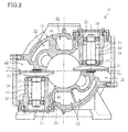
- FIGS. 1 and 2 are respectively a longitudinal cross-sectional view and a transverse cross-sectional view that show a configuration for a screw compressor.
- a compression mechanism (20) and a motor (12) which is configured to drive the compression mechanism (20) are housed in a metallic casing (11).
- the compression mechanism (20) is coupled to the motor (12) via a drive shaft (21).
- the inside of the casing (11) is divided into a low-pressure space (S1) into which a low-pressure gaseous refrigerant flows, and a high-pressure space (S2) into which a high-pressure gaseous refrigerant that has been discharged from the compression mechanism (20) flows.
- S1 low-pressure space
- S2 high-pressure space
- the motor (12) includes a stator (13) and a rotor (14).
- the stator (13) is fixed to the inner peripheral surface of the casing (11) in the low-pressure space (S1).
- the compression mechanism (20) includes a cylindrical wall (16) provided inside the casing (11), a screw rotor (40) arranged inside the cylindrical wall (16), and two gate rotors (50) meshing with the screw rotor (40).
- the screw rotor (40) is a metallic member with a generally circular cylindrical shape.
- the outside diameter of the screw rotor (40) is set to be slightly smaller than the inside diameter of the cylindrical wall (16) such that the outer peripheral surface of the screw rotor (40) is in sliding contact with the inner peripheral surface of the cylindrical wall (16).
- the screw rotor (40) has, on its outer peripheral portion, a plurality of helical grooves (41) which helically extend from one axial end toward the other axial end of the screw rotor (40).
- the screw rotor (40) is penetrated by the drive shaft (21).
- the screw rotor (40) is coupled to the drive shaft (21) by means of a key (22).
- Each gate rotor (50) has a plurality of gates (51) which extend radially (see FIG. 5 ). Each gate rotor (50) is mounted on an associated one of metallic rotor support members (55). Each rotor support member (55) is arranged in an associated one of gate rotor chambers (18) which are defined in the casing (11) adjacent to the cylindrical wall (16).
- the rotor support member (55) shown on the right of the screw rotor (40) is arranged such that the associated gate rotor (50) is located at the lower end thereof.
- the rotor support member (55) shown on the left of the screw rotor (40) is arranged such that the associated gate rotor (50) is located at the upper end thereof.
- Each rotor support member (55) has its shaft (58) rotatably supported, via ball bearings (53), by a bearing housing (52) provided inside the associated gate rotor chamber (18).
- One end portion of the drive shaft (21) is rotatably supported by a low-pressure-side bearing (66) which is arranged in the low-pressure space (S1).
- the low-pressure-side bearing (66) is held by a low-pressure-side bearing holder (65).
- the other end portion of the drive shaft (21) is rotatably supported by a high-pressure-side bearing (61) arranged on the high-pressure side of the compression mechanism (20).
- the high-pressure-side bearing (61) is held by a high-pressure-side bearing holder (60) which is fitted into the cylindrical wall (16) of the casing (11).
- the casing (11) has a suction port (11a) beside the low-pressure space (S1). As viewed in the axial direction, the suction port (11a) is positioned such that its opening faces the low-pressure-side bearing holder (65). (In FIG. 1 , the opening is located at the center of the left end of the casing (11).)
- the suction port (11a) has a filter member (30) attached thereto in order to filter out contaminants of relatively large sizes which are contained in the gaseous refrigerant that is being sucked into the casing (11).
- the filter member (30) includes a mesh filter body (31) which is in a cylindrical shape having a bottom, and a flange (32) which projects radially outward from a peripheral portion adjacent to the opening of the filter body (31).
- the filter body (31) is designed to have such a length that when the filter body (31) is inserted into the casing (11) through the suction port (11a), the bottom of the filter body (31) is in contact with the low-pressure-side bearing holder (65).
- the flange (32) is in contact with the peripheral portion of the suction port (11a) when the bottom of the filter body (31) is in contact with the low-pressure-side bearing holder (65).
- the flange (32) is retained between the peripheral portion of the suction port (11a) of the casing (11) and a ring-like fixing lid (38).
- the fixing lid (38) is fastened to the casing (11) with fastening bolts (35). In this manner, the peripheral portion of the filter member (30) adjacent to its opening is fixed to the suction port (11a).
- FIGS. 3 and 4 are respectively a perspective view and a bottom view that show a configuration for the filter member.
- an annular frame (33) and a reinforcing member (34) are attached to the bottom of the filter member (30).
- the reinforcing member (34) is attached to, and extends across, the frame (33).
- the frame (33) extends along the peripheral edge of the bottom of the filter body (31), which allows for increasing the stiffness of the bottom of the filter body (31).
- the reinforcing member (34) is configured as a plate-like member which extends in the radial direction of the filter body (31).
- the reinforcing member (34) has, at its center, an insertion hole (34a) through which the axis of another fastening bolt (35) is inserted.
- the bottom of the filter body (31) also has a hole which corresponds to the insertion hole (34a).
- the low-pressure-side bearing holder (65) has a screw hole (not shown) which corresponds to the insertion hole (34a).
- the bottom of the filter body (31) is fastened to the low-pressure-side bearing holder (65) via the reinforcing member (34) and with the fastening bolt (35).
- this configuration allows for preventing the filter member (30) from being buckled and deformed in the axial direction and increasing the strength of the filter member (30), even if the high-pressure gas in the high-pressure space (S2) flows backward through the helical grooves (41) of the screw rotor (40) and enters the low-pressure space (S1) to apply an external pressure to the filter member (30) when the screw rotor (40) is not rotating.
- the casing (11) has, in its high-pressure space (S2), a discharge port (11b).
- the discharge port (11b) has its opening at the right end of the casing (11).
- the high-pressure refrigerant is discharged out of the casing (11) through the discharge port (11b).
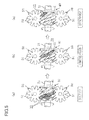
- the shaded compression chambers (23) communicate with the low-pressure space (S1).
- the helical grooves (41) that form these compression chambers (23) are meshed with associated ones of the gates (51) of the gate rotor (50) that is shown at the bottom of Portion (a) of FIG. 5 .
- the rotation of the screw rotor (40) results in relative movement of the associated gates (51) toward the terminal ends of the helical grooves (41).
- the volumes of the compression chambers (23) increase.
- the low-pressure gaseous refrigerant in the low-pressure space (S1) is sucked into the compression chambers (23) through the suction section (24).
- the compression mechanism enters the state shown in Portion (b) of FIG. 5 .
- the shaded compression chamber (23) is completely closed.
- the helical groove (41) that forms this compression chamber (23) is meshed with an associated one of the gates (51) of the gate rotor (50) that is shown at the top of Portion (b) of FIG. 5 , and this associated gate (51) separates the compression chamber from the low-pressure space (S1).
- the rotation of the screw rotor (40) results in movement of the associated gate (51) toward the terminal end of the helical groove (41), and consequently, the volume of the compression chamber (23) gradually decreases. As a result, the gaseous refrigerant present in the compression chamber (23) is compressed.
- the compression mechanism When the screw rotor (40) further rotates, the compression mechanism enters the state shown in Portion (c) of FIG. 5 .
- the shaded compression chamber (23) In Portion (c) of FIG. 5 , the shaded compression chamber (23) is in communication with the high-pressure space (S2) through the discharge port (not shown).
- the rotation of the screw rotor (40) results in movement of the associated gate (51) toward the terminal end of the helical groove (41), and consequently, the compressed gaseous refrigerant is pushed out of the compression chamber (23) to enter the high-pressure space (S2).
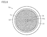
- FIG. 6 corresponds to FIG. 3 and shows a configuration for a filter member according to a variation of the present invention.
- an annular frame (33) which extends along the peripheral edge of the bottom of the filter member (30) is attached to the bottom of the filter member (30).
- a reinforcing member (34) is also attached to the center of the bottom of the filter member (30).
- the reinforcing member (34) is configured as a square plate with which the head of a fastening bolt (35) is to be in contact.
- the reinforcing member (34) has, at its center, an insertion hole (34a) through which the axis of the fastening bolt (35) is inserted.
- FIG. 6 shows an embodiment in which the annular frame (33) is attached, the frame (33) does not have to be provided.
- the reinforcing member (34) is not limited to any particular shape, but may have a ring shape, for example.
- the present invention prevents a filter member in a cylindrical shape having a bottom from being buckled and deformed when an external pressure is applied to the filter member, which is so advantageous in practice that the present invention is very useful and has a broad range of industrial applicability.
Landscapes
- Engineering & Computer Science (AREA)
- Mechanical Engineering (AREA)
- General Engineering & Computer Science (AREA)
- Applications Or Details Of Rotary Compressors (AREA)
Abstract
Description
- The present invention relates to a screw compressor.
- A screw compressor of the known art includes a casing and a screw rotor which is arranged in the casing and which constitutes a compression mechanism for compressing a refrigerant (see, for example, Patent Document 1).
- This screw compressor includes a mesh filter which is attached to its suction port so as to filter out contaminants contained in the refrigerant being sucked. To facilitate maintenance, the filter adopted in this screw compressor is a cartridge type one in a cylindrical shape having a bottom.
- PATENT DOCUMENT 1: Japanese Unexamined Patent Publication No.
2002-070778 - In the crew compressor of the known art, however, a peripheral portion of the filter adjacent to its opening is fixed to the suction port of the screw compressor, and the cylindrical mesh portion of the filter extends inside the casing. Therefore, this mesh portion may be buckled and deformed.
- Specifically, in the screw compressor, the discharge port of the compression mechanism is always open. Consequently, if the rotation of the screw rotor is stopped, a high-pressure gas in a high-pressure space flows backward through helical grooves of the screw rotor to enter a low-pressure space. Here, the filter in a cylindrical shape having a bottom has sufficient strength with respect to the internal pressure of a refrigerant which goes from the inside to the outside of the filter, but is easily deformed under the external pressure of the refrigerant which goes from the outside to the inside of the filter. That is to say, if the high-pressure gas flows backward in the manner as described above, the external pressure is applied to the filter, which adversely causes buckling deformation to the mesh portion of the filter in the axial direction.
- Here, it may be possible to prevent the buckling deformation by reinforcing the filter either by covering the mesh portion of the filter with a punched plate or by attaching a steel plate member in the axial direction of the filter. However, the more strongly the filter is reinforced, the smaller the effective area of the filter becomes. This results in an increase in the pressure loss of the refrigerant and a decrease in suction efficiency.
- In view of the foregoing, it is therefore an object of the present invention to prevent a filter member in a cylindrical shape having a bottom from being buckled and deformed when an external pressure is applied to the filter member.
- The present invention relates to a screw compressor including: a casing (11); a screw rotor (40) which is housed in the casing (11) and constitutes a compression mechanism (20) to compress a refrigerant; a low-pressure-side bearing (66) which is arranged in a low-pressure-side region inside the casing (11) and rotatably supports a drive shaft (21) of the screw rotor (40); and a low-pressure-side bearing holder (65) which holds the low-pressure-side bearing (66). The screw compressor of the present invention has the following feature as a means for solving the problem described above.
- Specifically, in a screw compressor according to a first aspect of the present invention, the casing (11) has a suction port (11a), of which an opening faces the low-pressure-side bearing holder (65) as viewed in an axial direction, a filter member (30) is attached to the suction port (11a) to filter out contaminants contained in the refrigerant which is being sucked into the casing (11), and the filter member (30) is in a cylindrical shape having a bottom, where a peripheral portion of the filter member (30) adjacent to an opening thereof is fixed to the suction port (11a) while a bottom of the filter member (30) is fixed to the low-pressure-side bearing holder (65).
- According to the first aspect of the present invention, the casing (11) has a suction port (11a), of which an opening faces a low-pressure-side bearing holder (65) as viewed in an axial direction. A filter member (30) which is in a cylindrical shape having a bottom is attached to the suction port (11a). A peripheral portion of the filter member (30) adjacent to its opening is fixed to the suction port (11a). Further, a bottom of the filter member (30) is fixed to the low-pressure-side bearing holder (65).
- This configuration allows for preventing the filter member (30) in a cylindrical shape having a bottom from being buckled and deformed when an external pressure is applied to the filter member (30).
- Specifically, in the screw compressor, the discharge port of the compression mechanism (20) is always open. Therefore, when the rotation of the screw rotor (40) is stopped, a high-pressure gas in a high-pressure space (S2) flows backward through helical grooves (41) of the screw rotor (40) to enter a low-pressure space (S1), which results in that an external pressure is applied to the filter member (30).
- According to the first aspect of the present invention, the bottom of the filter member (30) is fixed to the low-pressure-side bearing holder (65). Therefore, even if an external pressure is applied to the filter member (30), no buckling deformation is allowed to occur in the filter member (30) in the axial direction. Thus, the strength of the filter member (30) can be increased. In addition, the present invention eliminates the need for separately providing a punched plate or other members for the purpose of reinforcing the filter member (30), which allows for reducing the cost.
- A second aspect of the present invention is an embodiment of the screw compressor according to the first aspect. In the second aspect, a reinforcing member (34) is attached to the bottom of the filter member (30) and fastened to the low-pressure-side bearing holder (65) with a fastening bolt (35).
- According to the second aspect of the present invention, a reinforcing member (34) is attached to the bottom of the filter member (30). The reinforcing member (34) is fastened to the low-pressure-side bearing holder (65) with a fastening bolt (35). This configuration allows for ensuring some strength for the filter member (30).
- Here, if the mesh portion at the bottom of the filter member (30) was fastened directly with a fastening bolt (35), the application of an external pressure to the filter member (30) could cause stress concentration around the head of the fastening bolt (35), which could rupture the bottom of the filter member (30).
- To address this problem, according to the second aspect of the present invention, the bottom of the filter member (30) is fastened to the low-pressure-side bearing holder (65) via the reinforcing member (34) and with the fastening bolt (35). This configuration makes it difficult to rupture the mesh portion of the bottom of the filter member (30), and ensures sufficient strength for the filter member (30). In addition, the portion reinforced by the reinforcing member (34) is minimized, and therefore, a large effective filter area is ensured, which allows for reducing the pressure loss of the refrigerant.
- A third aspect of the present invention is an embodiment of the screw compressor according to the second aspect. In the third aspect, an annular frame (33) which extends along a peripheral edge of the bottom of the filter member (30) is attached to the bottom of the filter member (30), the reinforcing member (34) is configured as a plate-like member which extends along the bottom of the filter member (30) in a radial direction, and the reinforcing member (34) is attached to, and extends across, the frame (33), and thereby attached to the bottom of the filter member (30).
- According to the third aspect of the present invention, an annular frame (33) extending along a peripheral edge of the bottom of the filter member (30) is attached to the bottom of the filter member (30). The reinforcing member (34) is configured as a plate-like member which extends along the bottom of the filter member (30) in a radial direction. The reinforcing member (34) is attached to, and extends across, the frame (33).
- This configuration, in which the peripheral edge of the bottom of the filter member (30) is reinforced by the frame (33), allows for increasing the stiffness of the filter member (30). The reinforcing member (34) that is attached to, and extends across, the frame (33) in the radial direction functions as a reinforcing beam, which allows for further increasing the stiffness of the filter member (30).
- According to the present invention, since the bottom of the filter member (30) is fixed to the low-pressure-side bearing holder (65), no buckling deformation is allowed to occur in the filter member (30) in the axial direction even if an external pressure is applied to the filter member (30). Thus, the strength of the filter member (30) is increased. In addition, the present invention eliminates the need for separately providing a punched plate or other members for the purpose of reinforcing the filter member (30), which allows for reducing the cost.
-
- [
FIG. 1] FIG. 1 is a longitudinal cross-sectional view showing a configuration for a screw compressor according to an embodiment of the present invention. - [
FIG. 2] FIG. 2 is a transverse cross-sectional view showing a configuration for the screw compressor. - [
FIG. 3] FIG. 3 is a perspective view showing a configuration for a filter member. - [
FIG. 4] FIG. 4 is a bottom view showing a configuration for the filter member. - [
FIG. 5 ] Portions (a) to (c) ofFIG. 5 are plan views showing an operation of a compression mechanism of the screw compressor, wherein (a) shows a suction stroke, (b) shows a compression stroke, and (c) shows a discharge stroke. - [
FIG. 6] FIG. 6 is a view corresponding toFIG. 4 and showing a configuration for a filter member according to a variation of the present invention. - Embodiments of the present invention will be described below with reference to the drawings. Note that the following embodiments are merely preferred examples in nature, and are not intended to limit the scope, applications, and use of the invention.
-
FIGS. 1 and2 are respectively a longitudinal cross-sectional view and a transverse cross-sectional view that show a configuration for a screw compressor. As show inFIGS. 1 and2 , in the screw compressor (10), a compression mechanism (20) and a motor (12) which is configured to drive the compression mechanism (20) are housed in a metallic casing (11). The compression mechanism (20) is coupled to the motor (12) via a drive shaft (21). - The inside of the casing (11) is divided into a low-pressure space (S1) into which a low-pressure gaseous refrigerant flows, and a high-pressure space (S2) into which a high-pressure gaseous refrigerant that has been discharged from the compression mechanism (20) flows.
- The motor (12) includes a stator (13) and a rotor (14). The stator (13) is fixed to the inner peripheral surface of the casing (11) in the low-pressure space (S1). The drive shaft (21), of which one end portion is coupled to the rotor (14), rotates along with the rotor (14).
- The compression mechanism (20) includes a cylindrical wall (16) provided inside the casing (11), a screw rotor (40) arranged inside the cylindrical wall (16), and two gate rotors (50) meshing with the screw rotor (40).
- The screw rotor (40) is a metallic member with a generally circular cylindrical shape. The outside diameter of the screw rotor (40) is set to be slightly smaller than the inside diameter of the cylindrical wall (16) such that the outer peripheral surface of the screw rotor (40) is in sliding contact with the inner peripheral surface of the cylindrical wall (16). The screw rotor (40) has, on its outer peripheral portion, a plurality of helical grooves (41) which helically extend from one axial end toward the other axial end of the screw rotor (40).
- The screw rotor (40) is penetrated by the drive shaft (21). The screw rotor (40) is coupled to the drive shaft (21) by means of a key (22).
- Each gate rotor (50) has a plurality of gates (51) which extend radially (see
FIG. 5 ). Each gate rotor (50) is mounted on an associated one of metallic rotor support members (55). Each rotor support member (55) is arranged in an associated one of gate rotor chambers (18) which are defined in the casing (11) adjacent to the cylindrical wall (16). - In
FIG. 2 , the rotor support member (55) shown on the right of the screw rotor (40) is arranged such that the associated gate rotor (50) is located at the lower end thereof. On the other hand, inFIG. 2 , the rotor support member (55) shown on the left of the screw rotor (40) is arranged such that the associated gate rotor (50) is located at the upper end thereof. Each rotor support member (55) has its shaft (58) rotatably supported, via ball bearings (53), by a bearing housing (52) provided inside the associated gate rotor chamber (18). - In the compression mechanism (20), spaces surrounded by the inner peripheral surface of the cylindrical wall (16), the helical grooves (41) of the screw rotor (40), and the gates (51) of the gate rotors (50) serve as compression chambers (23). The suction side ends of the helical grooves (41) of the screw rotor (40) are opened to the low-pressure space (S1). These openings of the helical grooves (41) serve as a suction section (24) of the compression mechanism (20).
- One end portion of the drive shaft (21) is rotatably supported by a low-pressure-side bearing (66) which is arranged in the low-pressure space (S1). The low-pressure-side bearing (66) is held by a low-pressure-side bearing holder (65). The other end portion of the drive shaft (21) is rotatably supported by a high-pressure-side bearing (61) arranged on the high-pressure side of the compression mechanism (20). The high-pressure-side bearing (61) is held by a high-pressure-side bearing holder (60) which is fitted into the cylindrical wall (16) of the casing (11).
- The casing (11) has a suction port (11a) beside the low-pressure space (S1). As viewed in the axial direction, the suction port (11a) is positioned such that its opining faces the low-pressure-side bearing holder (65). (In
FIG. 1 , the opening is located at the center of the left end of the casing (11).) The suction port (11a) has a filter member (30) attached thereto in order to filter out contaminants of relatively large sizes which are contained in the gaseous refrigerant that is being sucked into the casing (11). - The filter member (30) includes a mesh filter body (31) which is in a cylindrical shape having a bottom, and a flange (32) which projects radially outward from a peripheral portion adjacent to the opening of the filter body (31).
- The filter body (31) is designed to have such a length that when the filter body (31) is inserted into the casing (11) through the suction port (11a), the bottom of the filter body (31) is in contact with the low-pressure-side bearing holder (65).
- The flange (32) is in contact with the peripheral portion of the suction port (11a) when the bottom of the filter body (31) is in contact with the low-pressure-side bearing holder (65). The flange (32) is retained between the peripheral portion of the suction port (11a) of the casing (11) and a ring-like fixing lid (38). The fixing lid (38) is fastened to the casing (11) with fastening bolts (35). In this manner, the peripheral portion of the filter member (30) adjacent to its opening is fixed to the suction port (11a).
-
FIGS. 3 and 4 are respectively a perspective view and a bottom view that show a configuration for the filter member. As shown inFIGS. 3 and 4 , an annular frame (33) and a reinforcing member (34) are attached to the bottom of the filter member (30). The reinforcing member (34) is attached to, and extends across, the frame (33). - The frame (33) extends along the peripheral edge of the bottom of the filter body (31), which allows for increasing the stiffness of the bottom of the filter body (31).
- The reinforcing member (34) is configured as a plate-like member which extends in the radial direction of the filter body (31). The reinforcing member (34) has, at its center, an insertion hole (34a) through which the axis of another fastening bolt (35) is inserted. The bottom of the filter body (31) also has a hole which corresponds to the insertion hole (34a). The low-pressure-side bearing holder (65) has a screw hole (not shown) which corresponds to the insertion hole (34a).
- As shown in
FIG. 1 , the bottom of the filter body (31) is fastened to the low-pressure-side bearing holder (65) via the reinforcing member (34) and with the fastening bolt (35). Thus, this configuration allows for preventing the filter member (30) from being buckled and deformed in the axial direction and increasing the strength of the filter member (30), even if the high-pressure gas in the high-pressure space (S2) flows backward through the helical grooves (41) of the screw rotor (40) and enters the low-pressure space (S1) to apply an external pressure to the filter member (30) when the screw rotor (40) is not rotating. - The casing (11) has, in its high-pressure space (S2), a discharge port (11b). In
FIG. 1 , the discharge port (11b) has its opening at the right end of the casing (11). The high-pressure refrigerant is discharged out of the casing (11) through the discharge port (11b). - The operation of the screw compressor (10) will now be described below. As shown in
FIG. 1 , when the motor (12) of the screw compressor (10) is started, the drive shaft (21) rotates to make the screw rotor (40) rotate. This rotation of the screw rotor (40) also makes the gate rotors (50) rotate, which results in that the compression mechanism (20) performs the same series of suction, compression, and discharge strokes a number of times. Here, these strokes will be described with attention focused on the compression chambers (23) indicated by shading inFIG. 5 . - In Portion (a) of
FIG. 5 , the shaded compression chambers (23) communicate with the low-pressure space (S1). The helical grooves (41) that form these compression chambers (23) are meshed with associated ones of the gates (51) of the gate rotor (50) that is shown at the bottom of Portion (a) ofFIG. 5 . The rotation of the screw rotor (40) results in relative movement of the associated gates (51) toward the terminal ends of the helical grooves (41). Along with this relative movement, the volumes of the compression chambers (23) increase. As a result, the low-pressure gaseous refrigerant in the low-pressure space (S1) is sucked into the compression chambers (23) through the suction section (24). - When the screw rotor (40) further rotates, the compression mechanism enters the state shown in Portion (b) of
FIG. 5 . In Portion (b) ofFIG. 5 , the shaded compression chamber (23) is completely closed. Specifically, the helical groove (41) that forms this compression chamber (23) is meshed with an associated one of the gates (51) of the gate rotor (50) that is shown at the top of Portion (b) ofFIG. 5 , and this associated gate (51) separates the compression chamber from the low-pressure space (S1). The rotation of the screw rotor (40) results in movement of the associated gate (51) toward the terminal end of the helical groove (41), and consequently, the volume of the compression chamber (23) gradually decreases. As a result, the gaseous refrigerant present in the compression chamber (23) is compressed. - When the screw rotor (40) further rotates, the compression mechanism enters the state shown in Portion (c) of
FIG. 5 . In Portion (c) ofFIG. 5 , the shaded compression chamber (23) is in communication with the high-pressure space (S2) through the discharge port (not shown). The rotation of the screw rotor (40) results in movement of the associated gate (51) toward the terminal end of the helical groove (41), and consequently, the compressed gaseous refrigerant is pushed out of the compression chamber (23) to enter the high-pressure space (S2). -
FIG. 6 corresponds toFIG. 3 and shows a configuration for a filter member according to a variation of the present invention. As shown inFIG. 6 , an annular frame (33) which extends along the peripheral edge of the bottom of the filter member (30) is attached to the bottom of the filter member (30). A reinforcing member (34) is also attached to the center of the bottom of the filter member (30). - The reinforcing member (34) is configured as a square plate with which the head of a fastening bolt (35) is to be in contact. The reinforcing member (34) has, at its center, an insertion hole (34a) through which the axis of the fastening bolt (35) is inserted. Thus, since the portion reinforced by the reinforcing member (34) is minimized, a large effective filter area is ensured, which allows for reducing the pressure loss of the refrigerant.
- Though
FIG. 6 shows an embodiment in which the annular frame (33) is attached, the frame (33) does not have to be provided. Also, the reinforcing member (34) is not limited to any particular shape, but may have a ring shape, for example. - As can be seen from the foregoing description, the present invention prevents a filter member in a cylindrical shape having a bottom from being buckled and deformed when an external pressure is applied to the filter member, which is so advantageous in practice that the present invention is very useful and has a broad range of industrial applicability.
-
- 10
- Screw Compressor
- 11
- Casing
- 11a
- Suction Port
- 20
- Compression Mechanism
- 21
- Drive Shaft
- 30
- Filter Member
- 33
- Frame
- 34
- Reinforcing Member
- 35
- Fastening Bolt
- 40
- Screw Rotor
- 65
- Low-pressure-side Bearing Holder
- 66
- Low-pressure-side Bearing
Claims (3)
- A screw compressor comprising: a casing (11); a screw rotor (40) which is housed in the casing (11) and constitutes a compression mechanism (20) to compress a refrigerant; a low-pressure-side bearing (66) which is arranged in a low-pressure-side region inside the casing (11) and rotatably supports a drive shaft (21) of the screw rotor (40); and a low-pressure-side bearing holder (65) which holds the low-pressure-side bearing (66), wherein
the casing (11) has a suction port (11a), of which an opening faces the low-pressure-side bearing holder (65) as viewed in an axial direction,
a filter member (30) is attached to the suction port (11a) to filter out contaminants contained in the refrigerant which is being sucked into the casing (11), and
the filter member (30) is in a cylindrical shape having a bottom, where a peripheral portion of the filter member (30) adjacent to an opening thereof is fixed to the suction port (11a) while a bottom of the filter member (30) is fixed to the low-pressure-side bearing holder (65). - The screw compressor of claim 1, wherein
a reinforcing member (34) is attached to the bottom of the filter member (30) and fastened to the low-pressure-side bearing holder (65) with a fastening bolt (35). - The screw compressor of claim 2, wherein
an annular frame (33) which extends along a peripheral edge of the bottom of the filter member (30) is attached to the bottom of the filter member (30),
the reinforcing member (34) is configured as a plate-like member which extends along the bottom of the filter member (30) in a radial direction, and
the reinforcing member (34) is attached to, and extends across, the frame (33), and thereby attached to the bottom of the filter member (30).
Applications Claiming Priority (2)
| Application Number | Priority Date | Filing Date | Title |
|---|---|---|---|
| JP2012274860A JP5527396B1 (en) | 2012-12-17 | 2012-12-17 | Screw compressor |
| PCT/JP2013/007336 WO2014097590A1 (en) | 2012-12-17 | 2013-12-12 | Screw compressor |
Publications (3)
| Publication Number | Publication Date |
|---|---|
| EP2933492A1 true EP2933492A1 (en) | 2015-10-21 |
| EP2933492A4 EP2933492A4 (en) | 2016-07-27 |
| EP2933492B1 EP2933492B1 (en) | 2019-10-30 |
Family
ID=50977953
Family Applications (1)
| Application Number | Title | Priority Date | Filing Date |
|---|---|---|---|
| EP13865652.5A Active EP2933492B1 (en) | 2012-12-17 | 2013-12-12 | Screw compressor |
Country Status (5)
| Country | Link |
|---|---|
| US (1) | US9771952B2 (en) |
| EP (1) | EP2933492B1 (en) |
| JP (1) | JP5527396B1 (en) |
| CN (1) | CN104884808B (en) |
| WO (1) | WO2014097590A1 (en) |
Families Citing this family (4)
| Publication number | Priority date | Publication date | Assignee | Title |
|---|---|---|---|---|
| CN105114323A (en) * | 2015-09-08 | 2015-12-02 | 无锡压缩机股份有限公司 | Cylinder block structure of screw compressor |
| JP6747572B2 (en) * | 2017-02-20 | 2020-08-26 | ダイキン工業株式会社 | Screw compressor |
| KR20200113680A (en) | 2019-03-26 | 2020-10-07 | 현대자동차주식회사 | Electric oil pump for hydraulic control |
| CN116906326B (en) * | 2023-08-14 | 2025-03-11 | 上海格素实业有限公司 | An oil-free screw air compressor |
Family Cites Families (18)
| Publication number | Priority date | Publication date | Assignee | Title |
|---|---|---|---|---|
| US3101171A (en) * | 1961-02-27 | 1963-08-20 | Ingersoll Rand Co | Axial flow compressor |
| JP3864452B2 (en) * | 1996-06-07 | 2006-12-27 | 松下電器産業株式会社 | Hermetic electric compressor |
| BE1010851A3 (en) * | 1997-01-15 | 1999-02-02 | Atlas Copco Airpower Nv | LIQUID INJECTED COMPRESSOR at least two cooperating compressor elements. |
| DE69811766T2 (en) * | 1997-05-16 | 2004-03-18 | Atlas Copco Airpower N.V. | COMPRESSORS WITH AT LEAST ONE COMPRESSION LEVEL AND A HUMIDITY SEPARATOR |
| JP3499110B2 (en) * | 1997-08-11 | 2004-02-23 | 株式会社神戸製鋼所 | Oil-cooled screw compressor |
| DE29904410U1 (en) * | 1999-03-10 | 2000-07-20 | GHH-RAND Schraubenkompressoren GmbH & Co. KG, 46145 Oberhausen | Screw compressor |
| JP3994220B2 (en) * | 2000-09-01 | 2007-10-17 | 株式会社日立製作所 | Screw compressor |
| JP3796210B2 (en) * | 2002-11-01 | 2006-07-12 | 株式会社神戸製鋼所 | Screw compressor |
| JP2004293295A (en) * | 2003-02-05 | 2004-10-21 | Toyota Industries Corp | Scroll type compressor and cooling method and purification method of gas in the same |
| JP5033351B2 (en) * | 2006-05-10 | 2012-09-26 | 日立アプライアンス株式会社 | Hermetic compressor for refrigerant |
| JP2008121479A (en) * | 2006-11-10 | 2008-05-29 | Hitachi Appliances Inc | Hermetic screw compressor |
| EP2246571A4 (en) * | 2008-01-23 | 2014-11-26 | Daikin Ind Ltd | SCREW COMPRESSOR |
| US8167595B2 (en) * | 2008-10-14 | 2012-05-01 | Bitzer Scroll Inc. | Inlet screen and scroll compressor incorporating same |
| JP2010223145A (en) * | 2009-03-25 | 2010-10-07 | Hitachi Appliances Inc | Screw compressor |
| JP2011001835A (en) * | 2009-06-16 | 2011-01-06 | Daikin Industries Ltd | Screw compressor |
| JP5383632B2 (en) * | 2010-11-26 | 2014-01-08 | 株式会社神戸製鋼所 | Screw compressor |
| JP5358608B2 (en) * | 2011-03-30 | 2013-12-04 | 日立アプライアンス株式会社 | Screw compressor and chiller unit using the same |
| CN102748285A (en) * | 2012-04-11 | 2012-10-24 | 无锡市制冷设备厂有限责任公司 | Screw compressor |
-
2012
- 2012-12-17 JP JP2012274860A patent/JP5527396B1/en not_active Expired - Fee Related
-
2013
- 2013-12-12 CN CN201380065890.8A patent/CN104884808B/en active Active
- 2013-12-12 EP EP13865652.5A patent/EP2933492B1/en active Active
- 2013-12-12 US US14/651,569 patent/US9771952B2/en active Active
- 2013-12-12 WO PCT/JP2013/007336 patent/WO2014097590A1/en not_active Ceased
Also Published As
| Publication number | Publication date |
|---|---|
| CN104884808B (en) | 2016-06-29 |
| EP2933492A4 (en) | 2016-07-27 |
| WO2014097590A1 (en) | 2014-06-26 |
| JP5527396B1 (en) | 2014-06-18 |
| US9771952B2 (en) | 2017-09-26 |
| JP2014118888A (en) | 2014-06-30 |
| EP2933492B1 (en) | 2019-10-30 |
| CN104884808A (en) | 2015-09-02 |
| US20150308458A1 (en) | 2015-10-29 |
Similar Documents
| Publication | Publication Date | Title |
|---|---|---|
| US9366253B2 (en) | Scroll compressor and processing method of scroll including a projection on a tip seal and a hole in a tip seal groove | |
| EP2933492B1 (en) | Screw compressor | |
| EP3712435A2 (en) | Motor-operated compressor | |
| EP2479435B1 (en) | Scroll compressor | |
| US10344804B2 (en) | Scroll compressor lower bearing | |
| US8535029B2 (en) | Scroll type compressor having reinforced fixed scroll | |
| US8092199B2 (en) | Scroll compressor including a plurality of shoulder sections | |
| AU2018310263B2 (en) | Oldham's ring and scroll compressor | |
| EP2894341B1 (en) | Compressor | |
| EP3492745B1 (en) | Scroll compressor | |
| US20170211390A1 (en) | Scroll type fluid machine | |
| EP2472114A1 (en) | Scroll fluid machine | |
| EP3951180A1 (en) | Scroll compressor | |
| EP3324049B1 (en) | Compressor | |
| EP2631426B1 (en) | Scroll compressor | |
| EP3540228A1 (en) | Screw compressor | |
| JP6432340B2 (en) | Rotary compressor | |
| EP3480467B1 (en) | Scroll compressor | |
| CN116971985A (en) | scroll compressor | |
| US20100111738A1 (en) | Scroll member, method of manufacturing same, compression mechanism and scroll compressor | |
| JP2013245621A (en) | Electric compressor | |
| JP2008240709A (en) | Compressor | |
| KR20130143326A (en) | Scroll compressor |
Legal Events
| Date | Code | Title | Description |
|---|---|---|---|
| PUAI | Public reference made under article 153(3) epc to a published international application that has entered the european phase |
Free format text: ORIGINAL CODE: 0009012 |
|
| 17P | Request for examination filed |
Effective date: 20150608 |
|
| AK | Designated contracting states |
Kind code of ref document: A1 Designated state(s): AL AT BE BG CH CY CZ DE DK EE ES FI FR GB GR HR HU IE IS IT LI LT LU LV MC MK MT NL NO PL PT RO RS SE SI SK SM TR |
|
| AX | Request for extension of the european patent |
Extension state: BA ME |
|
| RIN1 | Information on inventor provided before grant (corrected) |
Inventor name: INOUE, TAKASHI Inventor name: UENO, HIROMICHI |
|
| DAX | Request for extension of the european patent (deleted) | ||
| A4 | Supplementary search report drawn up and despatched |
Effective date: 20160629 |
|
| RIC1 | Information provided on ipc code assigned before grant |
Ipc: F04C 29/12 20060101AFI20160623BHEP Ipc: F04C 18/52 20060101ALI20160623BHEP Ipc: F04C 13/00 20060101ALI20160623BHEP Ipc: F04C 29/00 20060101ALI20160623BHEP |
|
| GRAP | Despatch of communication of intention to grant a patent |
Free format text: ORIGINAL CODE: EPIDOSNIGR1 |
|
| STAA | Information on the status of an ep patent application or granted ep patent |
Free format text: STATUS: GRANT OF PATENT IS INTENDED |
|
| RIC1 | Information provided on ipc code assigned before grant |
Ipc: F04C 29/00 20060101ALI20190617BHEP Ipc: F04C 18/52 20060101ALI20190617BHEP Ipc: F04C 29/12 20060101AFI20190617BHEP Ipc: F04C 13/00 20060101ALI20190617BHEP |
|
| INTG | Intention to grant announced |
Effective date: 20190722 |
|
| GRAS | Grant fee paid |
Free format text: ORIGINAL CODE: EPIDOSNIGR3 |
|
| GRAA | (expected) grant |
Free format text: ORIGINAL CODE: 0009210 |
|
| STAA | Information on the status of an ep patent application or granted ep patent |
Free format text: STATUS: THE PATENT HAS BEEN GRANTED |
|
| AK | Designated contracting states |
Kind code of ref document: B1 Designated state(s): AL AT BE BG CH CY CZ DE DK EE ES FI FR GB GR HR HU IE IS IT LI LT LU LV MC MK MT NL NO PL PT RO RS SE SI SK SM TR |
|
| REG | Reference to a national code |
Ref country code: GB Ref legal event code: FG4D |
|
| REG | Reference to a national code |
Ref country code: CH Ref legal event code: EP |
|
| REG | Reference to a national code |
Ref country code: AT Ref legal event code: REF Ref document number: 1196437 Country of ref document: AT Kind code of ref document: T Effective date: 20191115 |
|
| REG | Reference to a national code |
Ref country code: DE Ref legal event code: R096 Ref document number: 602013062358 Country of ref document: DE |
|
| REG | Reference to a national code |
Ref country code: IE Ref legal event code: FG4D |
|
| REG | Reference to a national code |
Ref country code: LT Ref legal event code: MG4D |
|
| PG25 | Lapsed in a contracting state [announced via postgrant information from national office to epo] |
Ref country code: FI Free format text: LAPSE BECAUSE OF FAILURE TO SUBMIT A TRANSLATION OF THE DESCRIPTION OR TO PAY THE FEE WITHIN THE PRESCRIBED TIME-LIMIT Effective date: 20191030 Ref country code: SE Free format text: LAPSE BECAUSE OF FAILURE TO SUBMIT A TRANSLATION OF THE DESCRIPTION OR TO PAY THE FEE WITHIN THE PRESCRIBED TIME-LIMIT Effective date: 20191030 Ref country code: LV Free format text: LAPSE BECAUSE OF FAILURE TO SUBMIT A TRANSLATION OF THE DESCRIPTION OR TO PAY THE FEE WITHIN THE PRESCRIBED TIME-LIMIT Effective date: 20191030 Ref country code: PT Free format text: LAPSE BECAUSE OF FAILURE TO SUBMIT A TRANSLATION OF THE DESCRIPTION OR TO PAY THE FEE WITHIN THE PRESCRIBED TIME-LIMIT Effective date: 20200302 Ref country code: ES Free format text: LAPSE BECAUSE OF FAILURE TO SUBMIT A TRANSLATION OF THE DESCRIPTION OR TO PAY THE FEE WITHIN THE PRESCRIBED TIME-LIMIT Effective date: 20191030 Ref country code: LT Free format text: LAPSE BECAUSE OF FAILURE TO SUBMIT A TRANSLATION OF THE DESCRIPTION OR TO PAY THE FEE WITHIN THE PRESCRIBED TIME-LIMIT Effective date: 20191030 Ref country code: PL Free format text: LAPSE BECAUSE OF FAILURE TO SUBMIT A TRANSLATION OF THE DESCRIPTION OR TO PAY THE FEE WITHIN THE PRESCRIBED TIME-LIMIT Effective date: 20191030 Ref country code: NL Free format text: LAPSE BECAUSE OF FAILURE TO SUBMIT A TRANSLATION OF THE DESCRIPTION OR TO PAY THE FEE WITHIN THE PRESCRIBED TIME-LIMIT Effective date: 20191030 Ref country code: NO Free format text: LAPSE BECAUSE OF FAILURE TO SUBMIT A TRANSLATION OF THE DESCRIPTION OR TO PAY THE FEE WITHIN THE PRESCRIBED TIME-LIMIT Effective date: 20200130 Ref country code: GR Free format text: LAPSE BECAUSE OF FAILURE TO SUBMIT A TRANSLATION OF THE DESCRIPTION OR TO PAY THE FEE WITHIN THE PRESCRIBED TIME-LIMIT Effective date: 20200131 Ref country code: BG Free format text: LAPSE BECAUSE OF FAILURE TO SUBMIT A TRANSLATION OF THE DESCRIPTION OR TO PAY THE FEE WITHIN THE PRESCRIBED TIME-LIMIT Effective date: 20200130 |
|
| REG | Reference to a national code |
Ref country code: NL Ref legal event code: MP Effective date: 20191030 |
|
| PG25 | Lapsed in a contracting state [announced via postgrant information from national office to epo] |
Ref country code: HR Free format text: LAPSE BECAUSE OF FAILURE TO SUBMIT A TRANSLATION OF THE DESCRIPTION OR TO PAY THE FEE WITHIN THE PRESCRIBED TIME-LIMIT Effective date: 20191030 Ref country code: RS Free format text: LAPSE BECAUSE OF FAILURE TO SUBMIT A TRANSLATION OF THE DESCRIPTION OR TO PAY THE FEE WITHIN THE PRESCRIBED TIME-LIMIT Effective date: 20191030 Ref country code: IS Free format text: LAPSE BECAUSE OF FAILURE TO SUBMIT A TRANSLATION OF THE DESCRIPTION OR TO PAY THE FEE WITHIN THE PRESCRIBED TIME-LIMIT Effective date: 20200229 |
|
| PG25 | Lapsed in a contracting state [announced via postgrant information from national office to epo] |
Ref country code: AL Free format text: LAPSE BECAUSE OF FAILURE TO SUBMIT A TRANSLATION OF THE DESCRIPTION OR TO PAY THE FEE WITHIN THE PRESCRIBED TIME-LIMIT Effective date: 20191030 |
|
| PG25 | Lapsed in a contracting state [announced via postgrant information from national office to epo] |
Ref country code: RO Free format text: LAPSE BECAUSE OF FAILURE TO SUBMIT A TRANSLATION OF THE DESCRIPTION OR TO PAY THE FEE WITHIN THE PRESCRIBED TIME-LIMIT Effective date: 20191030 Ref country code: CZ Free format text: LAPSE BECAUSE OF FAILURE TO SUBMIT A TRANSLATION OF THE DESCRIPTION OR TO PAY THE FEE WITHIN THE PRESCRIBED TIME-LIMIT Effective date: 20191030 Ref country code: EE Free format text: LAPSE BECAUSE OF FAILURE TO SUBMIT A TRANSLATION OF THE DESCRIPTION OR TO PAY THE FEE WITHIN THE PRESCRIBED TIME-LIMIT Effective date: 20191030 Ref country code: DK Free format text: LAPSE BECAUSE OF FAILURE TO SUBMIT A TRANSLATION OF THE DESCRIPTION OR TO PAY THE FEE WITHIN THE PRESCRIBED TIME-LIMIT Effective date: 20191030 |
|
| REG | Reference to a national code |
Ref country code: DE Ref legal event code: R097 Ref document number: 602013062358 Country of ref document: DE Ref country code: CH Ref legal event code: PL |
|
| REG | Reference to a national code |
Ref country code: AT Ref legal event code: MK05 Ref document number: 1196437 Country of ref document: AT Kind code of ref document: T Effective date: 20191030 |
|
| REG | Reference to a national code |
Ref country code: BE Ref legal event code: MM Effective date: 20191231 |
|
| PG25 | Lapsed in a contracting state [announced via postgrant information from national office to epo] |
Ref country code: SM Free format text: LAPSE BECAUSE OF FAILURE TO SUBMIT A TRANSLATION OF THE DESCRIPTION OR TO PAY THE FEE WITHIN THE PRESCRIBED TIME-LIMIT Effective date: 20191030 Ref country code: SK Free format text: LAPSE BECAUSE OF FAILURE TO SUBMIT A TRANSLATION OF THE DESCRIPTION OR TO PAY THE FEE WITHIN THE PRESCRIBED TIME-LIMIT Effective date: 20191030 Ref country code: MC Free format text: LAPSE BECAUSE OF FAILURE TO SUBMIT A TRANSLATION OF THE DESCRIPTION OR TO PAY THE FEE WITHIN THE PRESCRIBED TIME-LIMIT Effective date: 20191030 |
|
| PLBE | No opposition filed within time limit |
Free format text: ORIGINAL CODE: 0009261 |
|
| STAA | Information on the status of an ep patent application or granted ep patent |
Free format text: STATUS: NO OPPOSITION FILED WITHIN TIME LIMIT |
|
| 26N | No opposition filed |
Effective date: 20200731 |
|
| PG25 | Lapsed in a contracting state [announced via postgrant information from national office to epo] |
Ref country code: LU Free format text: LAPSE BECAUSE OF NON-PAYMENT OF DUE FEES Effective date: 20191212 Ref country code: FR Free format text: LAPSE BECAUSE OF NON-PAYMENT OF DUE FEES Effective date: 20191230 Ref country code: IE Free format text: LAPSE BECAUSE OF NON-PAYMENT OF DUE FEES Effective date: 20191212 |
|
| PG25 | Lapsed in a contracting state [announced via postgrant information from national office to epo] |
Ref country code: AT Free format text: LAPSE BECAUSE OF FAILURE TO SUBMIT A TRANSLATION OF THE DESCRIPTION OR TO PAY THE FEE WITHIN THE PRESCRIBED TIME-LIMIT Effective date: 20191030 Ref country code: SI Free format text: LAPSE BECAUSE OF FAILURE TO SUBMIT A TRANSLATION OF THE DESCRIPTION OR TO PAY THE FEE WITHIN THE PRESCRIBED TIME-LIMIT Effective date: 20191030 Ref country code: BE Free format text: LAPSE BECAUSE OF NON-PAYMENT OF DUE FEES Effective date: 20191231 Ref country code: LI Free format text: LAPSE BECAUSE OF NON-PAYMENT OF DUE FEES Effective date: 20191231 Ref country code: CH Free format text: LAPSE BECAUSE OF NON-PAYMENT OF DUE FEES Effective date: 20191231 |
|
| PG25 | Lapsed in a contracting state [announced via postgrant information from national office to epo] |
Ref country code: CY Free format text: LAPSE BECAUSE OF FAILURE TO SUBMIT A TRANSLATION OF THE DESCRIPTION OR TO PAY THE FEE WITHIN THE PRESCRIBED TIME-LIMIT Effective date: 20191030 |
|
| PG25 | Lapsed in a contracting state [announced via postgrant information from national office to epo] |
Ref country code: MT Free format text: LAPSE BECAUSE OF FAILURE TO SUBMIT A TRANSLATION OF THE DESCRIPTION OR TO PAY THE FEE WITHIN THE PRESCRIBED TIME-LIMIT Effective date: 20191030 Ref country code: HU Free format text: LAPSE BECAUSE OF FAILURE TO SUBMIT A TRANSLATION OF THE DESCRIPTION OR TO PAY THE FEE WITHIN THE PRESCRIBED TIME-LIMIT; INVALID AB INITIO Effective date: 20131212 |
|
| PG25 | Lapsed in a contracting state [announced via postgrant information from national office to epo] |
Ref country code: TR Free format text: LAPSE BECAUSE OF FAILURE TO SUBMIT A TRANSLATION OF THE DESCRIPTION OR TO PAY THE FEE WITHIN THE PRESCRIBED TIME-LIMIT Effective date: 20191030 |
|
| PG25 | Lapsed in a contracting state [announced via postgrant information from national office to epo] |
Ref country code: MK Free format text: LAPSE BECAUSE OF FAILURE TO SUBMIT A TRANSLATION OF THE DESCRIPTION OR TO PAY THE FEE WITHIN THE PRESCRIBED TIME-LIMIT Effective date: 20191030 |
|
| P01 | Opt-out of the competence of the unified patent court (upc) registered |
Effective date: 20230525 |
|
| PGFP | Annual fee paid to national office [announced via postgrant information from national office to epo] |
Ref country code: DE Payment date: 20241029 Year of fee payment: 12 |
|
| PGFP | Annual fee paid to national office [announced via postgrant information from national office to epo] |
Ref country code: GB Payment date: 20241031 Year of fee payment: 12 |
|
| PGFP | Annual fee paid to national office [announced via postgrant information from national office to epo] |
Ref country code: IT Payment date: 20241112 Year of fee payment: 12 |