EP2933392A1 - Rat barrier with smooth and toothed shutters - Google Patents
Rat barrier with smooth and toothed shutters Download PDFInfo
- Publication number
- EP2933392A1 EP2933392A1 EP15163734.5A EP15163734A EP2933392A1 EP 2933392 A1 EP2933392 A1 EP 2933392A1 EP 15163734 A EP15163734 A EP 15163734A EP 2933392 A1 EP2933392 A1 EP 2933392A1
- Authority
- EP
- European Patent Office
- Prior art keywords
- shutter
- barrier
- angular position
- sewage pipe
- edge
- Prior art date
- Legal status (The legal status is an assumption and is not a legal conclusion. Google has not performed a legal analysis and makes no representation as to the accuracy of the status listed.)
- Granted
Links
- 230000004888 barrier function Effects 0.000 title claims abstract description 376
- 239000010865 sewage Substances 0.000 claims abstract description 214
- 241000700159 Rattus Species 0.000 claims abstract description 116
- 241000283984 Rodentia Species 0.000 claims abstract description 111
- 238000011144 upstream manufacturing Methods 0.000 claims abstract description 41
- 239000007788 liquid Substances 0.000 claims description 81
- 239000007787 solid Substances 0.000 claims description 46
- 238000009434 installation Methods 0.000 claims description 30
- 230000001953 sensory effect Effects 0.000 claims description 14
- 239000010815 organic waste Substances 0.000 claims description 10
- 238000000034 method Methods 0.000 claims description 8
- XLYOFNOQVPJJNP-UHFFFAOYSA-N water Substances O XLYOFNOQVPJJNP-UHFFFAOYSA-N 0.000 description 23
- 230000005484 gravity Effects 0.000 description 17
- 230000008901 benefit Effects 0.000 description 14
- 238000011109 contamination Methods 0.000 description 8
- 210000000515 tooth Anatomy 0.000 description 7
- 230000000903 blocking effect Effects 0.000 description 3
- 239000011343 solid material Substances 0.000 description 3
- 241001465754 Metazoa Species 0.000 description 2
- 241000700157 Rattus norvegicus Species 0.000 description 2
- 241000700161 Rattus rattus Species 0.000 description 2
- 230000009286 beneficial effect Effects 0.000 description 2
- 230000000052 comparative effect Effects 0.000 description 2
- 230000000694 effects Effects 0.000 description 2
- 230000007246 mechanism Effects 0.000 description 2
- 235000004221 Brassica oleracea var gemmifera Nutrition 0.000 description 1
- 244000308368 Brassica oleracea var. gemmifera Species 0.000 description 1
- 235000002767 Daucus carota Nutrition 0.000 description 1
- 244000000626 Daucus carota Species 0.000 description 1
- 230000001154 acute effect Effects 0.000 description 1
- 230000008859 change Effects 0.000 description 1
- 230000006378 damage Effects 0.000 description 1
- 238000011010 flushing procedure Methods 0.000 description 1
- 239000006260 foam Substances 0.000 description 1
- 239000010985 leather Substances 0.000 description 1
- 230000003278 mimic effect Effects 0.000 description 1
- 238000005086 pumping Methods 0.000 description 1
- 230000009467 reduction Effects 0.000 description 1
- 230000000451 tissue damage Effects 0.000 description 1
- 231100000827 tissue damage Toxicity 0.000 description 1
- 235000013311 vegetables Nutrition 0.000 description 1
Images

Classifications
-
- E—FIXED CONSTRUCTIONS
- E03—WATER SUPPLY; SEWERAGE
- E03F—SEWERS; CESSPOOLS
- E03F7/00—Other installations or implements for operating sewer systems, e.g. for preventing or indicating stoppage; Emptying cesspools
- E03F7/06—Devices for restraining rats or other animals
Definitions
- the present invention relates to a rat barrier for installation in a sewage pipe, and more particularly a rat barrier with pivotally arranged shutters, use of such barrier and a pipe with such barrier.
- Barriers suitable for installation at least partly in a sewage pipe and for preventing rats or other rodents from passing the barrier in at least one direction of the sewage pipe are known in the art.
- EP 2 113 615 relates to a barrier for preventing rats or other rodents from entering a sewage pipe.
- the barrier comprises a support element that is mountable within the pipe, and a first shutter pivotally suspended within the support element for rotation about a horizontal axis and having a centre of gravity lying under the axis.
- the shutter is pivotable between a first angular position in which the first shutter is forming an acute angle with the direction of flow and at least substantially barring the aperture of the barrier, and a second angular position in which the first shutter is forming a second relatively smaller angle with the direction of flow thus keeping the aperture of the barrier at least partly open.
- a second shutter is placed upstream of a first shutter and is pivotally suspended about a second axis and having a centre of gravity located under the second axis.
- the first shutter can be suspended within the support element in two different orientations such that the direction in which the barrier blocks rodent from passing may be changed according to the needs without changing the orientation of the support element.
- An improved barrier suitable for installation at least partly in a sewage pipe and for preventing rats or other rodents from passing the barrier in at least one direction of the sewage pipe would be advantageous, and in particular a more efficient and reliable barrier would be advantageous.
- the above described object and several other objects are intended to be obtained in a first aspect of the invention by providing a barrier suitable for installation at least partly in a sewage pipe and for allowing a sewage flow within the sewage pipe to pass the barrier in a first direction of the sewage pipe, such as the first direction being a downstream direction, and for preventing rats or other rodents from passing the barrier in a second direction being opposite to the first direction upon installation of the barrier in the sewage pipe, such as the second direction being an upstream direction, said barrier comprising
- the invention may be particularly, but not exclusively, advantageous for obtaining a barrier, which may be effective in preventing rats from passing the barrier in at least one direction, since an edge of the second shutter is less smooth than a corresponding edge of the first shutter, whereby the second shutter may therefore exert a greater sensory stimulus to a rat or other rodent which tries to pass the barrier.
- a rat or other rodent trying to pass the barrier from the side facing the second shutter will have to be in physical contact with the edge of the second shutter, which second edge is less smooth than a corresponding edge of the first shutter, and which may therefore exert a greater sensory stimulus to the rat or other rodent, which may therefore give up and not pass the barrier.
- the invention may be particularly, but not exclusively, advantageous for obtaining a barrier, which may be more reliable, such as not being blocked by organic solid matter and other solid matter in, e.g., a sewage flow, since an edge of the first shutter is smoother than a corresponding edge of the second shutter, whereby the first shutter may therefore be less likely to attract organic solid matter and other solid matter in, e.g., a sewage flow, since such solid matter is less likely to get attached to, such as stick to, the smoother edge.
- the invention may be particularly, but not exclusively, advantageous for obtaining a barrier, which may be more reliable, such as not being blocked by organic solid matter and other solid matter in, e.g., a sewage flow, since an edge of the first shutter is smoother than a corresponding edge of the second shutter, which has the very surprising effect, that the second shutter may be less likely to attract organic solid matter and other solid matter in, e.g., a sewage flow.
- a more reliable and efficient barrier may be achieved by having shutters with different degrees of smoothness, so as to enable both effective blocking of rats and other rodent, and enabling a reduction of risk of blocking of the barrier with solid organic waste and other solid material, and it may in particular be seen as an insight of the present inventor that a contamination of the second shutter may be reduced by changing the first shutter.
- a 'barrier' may be understood as is common in the art and described in, e.g., European patent application EP 1 826 326 A1 and/or EP 2 113 615 B1 .
- the barrier may be positioned at least partially within a sewage pipe, such as partially within a sewage pipe and partially outside of a sewage pipe, such as partially in a well adjacent the sewage pipe, such as a completely inside a sewage pipe.
- the barrier may be located in a downstream sewage pipe to let rodents escape from a well and further away from housings.
- the barrier may also be used in an upstream sewage pipe so as to allow rats or other rodents to escape into a well and away from the upstream sewage pipe leading to, e.g. a housing.
- the barrier may be installed as described in, e.g., European patent application EP 1 826 326 A1 which is hereby incorporated in their entirety.
- a pipe may in general be understood to be any pipe, and in particular a sewage pipe, such as pipes for leading a sewage flow, such as any one of domestic sanitary, commercial, industrial, agricultural sewage flow and surface runoff.
- a sewage flow may pass the barrier, such as the barrier being arranged so that the flow resistance of the barrier in the first direction is small enough so as to allow a sewage flow to pass. It may be understood that in an embodiment, a flow resistance of the barrier in the first direction is smaller than a flow resistance in the second direction.
- the barrier may prevent rodent from passing the barrier in at least one direction, such as the second direction, such as an upstream direction. It may further be understood, that the barrier may not block rats or rodent from passing the barrier in the opposite direction, such as in the first direction, such as a downstream direction.
- the barrier may be installed in a pipe so as to allow a flow of liquid in a first direction, such as a downstream direction, and so as to block rats or other rodents from passing the barrier in a second direction, such as an upstream direction. It may be understood, that the barrier may not necessarily block passage of rats or other rodents in a downstream direction.
- 'first direction' may be understood a direction of flow of sewage in the sewage pipe, such as a downstream direction. While a pipe in itself may be symmetrical and as such not have any specific flow direction, it is in general understood, that a pipe, such as a sewage pipe, has a primary direction of flow, such as a direction of flow. The direction of flow may be the direction in which liquid typically flow through the pipe, such as due to gravity and/or pressure differences.
- 'first direction' is understood at direction being parallel with a longitudinal direction of the sewage pipe in a direction being similar to a direction in which flow of sewage is allowed by the barrier, such as a downstream direction.
- 'second direction' may be understood a direction in which rats or rodent are blocked.
- the second direction may be the upstream direction.
- 'second direction' is understood at direction being parallel with a longitudinal direction of the sewage pipe in a direction being similar to a direction in which rats or other rodents are being prevented from passing the barrier, where the second direction is opposite to the first direction, such as the second direction being an upstream direction.
- 'upstream direction' of a pipe may be understood a direction opposite the flow direction in the pipe.
- 'downstream direction' of a pipe may be understood a direction of flow of liquid in the pipe.
- a support structure' may be understood a structural part of the barrier in from which the shutters may be pivotally suspended.
- the support structure may comprise a part of the barrier not including the shutters or the entire barrier not including the shutters. It may be understood that the support structure may be structurally fixed to the sewage pipe, such as fixed via other structural elements in the barrier, such as fixed in an upper portion of the sewage pipe (with respect to gravity).
- At least one hinge' may be understood at least a one hinge, such as a first hinge, such as a first hinge and a second hinge.
- a 'shutter' may be understood as is common in the art, such as described in, e.g., European patent application EP 1 826 326 A1 and/or EP 2 113 615 B1 .
- a shutter may thus denote a structural element, such as a plate or a net or a set of bars, which may be pivotally suspended so as to facilitate barring an aperture in a first angular position and not barring the aperture in a second angular position.
- first shutter' and 'second shutter' may be understood shutters which are placed relative to each other, so that in case the barrier is installed in a pipe so as to allow a flow of liquid in a first direction, such as a downstream direction, and so as to block rats or other rodents from passing the barrier in a second direction, such as an upstream direction, the first shutter is placed upstream relative to the second shutter.
- the first shutter is the first shutter, which the water passes when flowing through the pipe, pass the barrier in a downstream direction, and a rat or other rodent trying to pass the barrier in an upstream direction will first face the second shutter.
- the first shutter and the second shutter may be arranged pivotably around each of their axes of rotation. They may be arranged so as to enable each of them to pivot independently from each other, although they may touch each other for certain combinations of angular values.
- each shutter is linked to the support structure, and may each pivot around an axis of rotation, such as a hinge in the support structure.
- the axis of rotation of the first shutter may or may not be identical to an axis of rotation of the second shutter.
- the first and second shutters have spatially separated axes of rotation.
- first shutter and the second shutter are at different positions, and that these positions spaced apart along the first direction, such as along a direction parallel with the flow, such as the first shutter is placed at a first position with respect to the first direction, and the second shutter is placed at another position with respect to the first direction, such as further downstream.
- position of the first shutter or the second shutter the position may be defined by the position of the centre of gravity of the respective shutter.
- An advantage of having the shutters spaced apart may be, that a rat or rodent trying to open the second shutter (where the second shutter may be the shutter the rat or rodent is facing when trying to pass the barrier in an upstream direction) by rotating it from the first angular position towards the second angular position, then the rat or rodent may have difficulties in handling the partially opened second shutter when it furthermore has to open the first shutter which is placed a little further upstream.
- the distance between the first shutter and the second shutter in the flow direction may be a distance arranged so as to be large enough that a rat or rodent cannot reach pass the second shutter and get hold of the first shutter and small enough that the rat or rodent cannot get pass, such as completely pass the second shutter, before having to open the first shutter.
- Said distance may be within 1-7 cm, such as 2-6 cm, such as 3-5 cm, such as substantially 4 cm, such as 4 cm. Said distance may advantageously be at least 30 mm. Said distance may advantageously be at most 50 mm. Said distance may be within 30-50 mm, such as 35 mm.
- a 'profile' may be understood as is common in the art, so as referring to an outline or contour. It may in the present context be understood, that shutters are generally flat, and that 'profile' refers to a profile of the edges of the generally flat shutters, such as the profile as observed in a direction orthogonal to a plane of the shutter.
- an edge' may be understood at least a part of an edge, such as at least a part of the edge of the first shutter or second shutter which - when the barrier is installed in a sewage pipe - would be accessible, such as immediately accessible, to rats or other rodents trying to pass the barrier and facing the shutter.
- a profile of at least a part of an edge of the first shutter is smoother than a profile of a corresponding part of an edge of the second shutter' may be understood that a profile of at least a part of an edge, such as at least a part of the edge of the first shutter which - when the barrier is installed in a sewage pipe - would be accessible, such as immediately accessible, to rats or other rodents trying to pass the barrier and facing the shutter, is smoother than a profile of a corresponding part of an edge of the second shutter.
- topographical features on the edge of the first shutter such as topographical features on the edge as observed from a direction away from the shutter where said direction is orthogonal to a plane of the shutter, may be larger and/or less smoothly than corresponding topographical features on the edge of the second shutter.
- degree of smoothness it may be understood, to be smoothness on a length scale (such as 1 mm or 1 cm), which may be sensed by a rat or other rodent.
- an edge may be less smooth by comprising pointy features, such as having any one of a saw-toothed profile, a toothed profile, a serrated profile and/or notched profile.
- edges may differ in smoothness due to differences in quantitative measures, e.g., by differing in any one of amplitude (such as maximum height differences between maximum and minimum points of the profile), frequency and/or phase of teeth.
- smoothness is to be understood to refer to a smoothness, which may be sensed by a rat or rodent upon touching said edge.
- the smoothness of a shutter may in a specific embodiment be quantified by the maximum distance between a line circumscribing the shutter and the largest distance between said line, such as 1 cm of said line being furthest from an axis of the pivotal mounting of said shutter, and the shutter.
- said distance is approximately 0 mm for the first (smooth) shutter 101 (because the circumscribed line is in contact with the shutter at the bottom part as depicted in Fig.
- the second shutter (102) (corresponding to the height of the teeths at the bottom portion of the shutter in the figure, because the circumscribed line only touches the top parts of the teeths, and the distance is thus the distance from top to to bottom of teeths).
- the size of the shutters is presumed similar to the size given in Fig. 9B .
- a part of the edge of the shutter which is immediately accessible to rats or other rodents trying to pass the barrier' may be understood a part of the edge which the rat may be most likely to touch upon, such as a part of the edge which the rat or rodent may reach, when being in front of the shutter, when the barrier is installed in a sewage pipe.
- the barrier may be installed in a sewage pipe as described in any one of EP 1 826 326 A2 or EP 2 113 615 A1 , which are both hereby incorporated by reference in entirety. It is furthermore noted, that said first shutter and second shutter may be capable of being positioned either in a first orientation in the barrier or in another orientation in the barrier, depending on the possible entering of the rodent, as described in EP 2 113 615 A1 , cf., e.g., claim 1, which is hereby incorporated by reference in entirety.
- the barrier according to the present invention may have a mounting mechanism comprising two wings, which each have a shape conforming to the sewage pipe interior, preferably the two wings has the shape of a part of the circumference of a circular pipe.
- the mounting mechanism may be expanded to establish a mounting of the barrier in the sewage pipe.
- the barrier may accordingly be mounted in standard circular pipes with various diameters because the barrier is insertable, at least partly, in such standard pipes. Additionally, the barrier is easy to replace and/or temporally remove for service and maintentence.
- a barrier wherein the barrier may be installed in a sewage pipe so that
- a barrier wherein the barrier may be installed in a sewage pipe so that each shutter within the group of shutters comprising the first shutter and the second shutter are pivotal between
- the barrier may be installed in a sewage pipe so that' may be understood that the claimed subject-matter is not confined to a barrier being installed in a sewage.
- a first angular position (v) in which the shutter is forming a first relatively larger angle with a direction of flow of sewage in the sewage pipe' may be understood an angular position of the shutter, such as an angular position being defined by the angle the shutter makes with a direction of flow, such as an angle between
- first angular position (v) is employed for each of the first shutter and the second shutter
- the angular value of said “first angular position (v)" for each of the first shutter and the second shutter need not necessarily be identical.
- an aperture of the barrier' may be understood barring an aperture of the barrier, such as enabling barrier access through a pipe in which the barrier is installed so as to enable preventing rats or other rodents from passing the barrier in at least one direction, such as an upstream direction.
- a second angular position (w) in which the shutter is forming a second relatively smaller angle with the direction of flow of sewage in the sewage pipe such as the first angular position and the second angular position being separated by less than 180 degrees
- an angular position of the shutter such as an angular position being defined by the angle the shutter makes with a direction of flow, such as an angle between
- second angular position (w) is employed for each of the first shutter and the second shutter
- the angular value of said “second angular position (w)" for each of the first shutter and the second shutter need not necessarily be identical.
- the aperture of the barrier at least partly open' may be understood as enabling a liquid flow, such as a flow of sewage, through a pipe in which the barrier is installed in at least one direction, such as a downstream direction, such as enabling a flow of sewage in a sewage pipe to pass the barrier.
- a barrier wherein the barrier is arranged so as to prevent each of the first shutter and the second shutter from pivoting beyond the first angular position (v) in a rotational direction away from the second angular position (w), such as preventing rats or other rodents from passing the barrier in at least one direction, such as said at least one direction being a direction opposite a direction of flow of sewage in the sewage pipe.
- each of the first shutter and the second shutter may not be able to rotate further in a direction away from the second angular position than the first angular position.
- This may be beneficial for preventing rats or other rodents from passing the barrier in at least one direction, since they will have to open the shutters by rotating them towards themselves, since they cannot push them the other way (away from themselves).
- the barrier may be configured to prevent the shutter from pivoting in an upstream direction (from the first angular position). This is relevant for preventing the rodent from passing the barrier in an upstream direction.
- a barrier wherein the first shutter is placed relative to the second shutter, so that when the first shutter is in the first angular position and rotating towards the second position, then a point on the first shutter below a rotational axis of the first shutter will move in a direction substantially towards the second shutter, such as towards the second shutter.
- the first shutter By 'wherein the first shutter is placed relative to the second shutter, so that when the first shutter is in the first angular position and rotating towards the second position, then a point on the first shutter below a rotational axis of the first shutter will move in a direction substantially towards the second shutter, such as towards the second shutter' may be understood that when the barrier is installed in, e.g., a sewage pipe, then the first shutter may be arranged so that when it is in the first angular position, such as substantially blocking the aperture of the barrier and pipe, then a lower portion of the first shutter may pivot towards the second shutter when the shutter pivots from a first angular position towards the second angular position. It may in general be understood, that the direction of rotation from the first angular position to the second angular position is similar for each of the first shutter and the second shutter.
- 'Rotational direction' may be understood as is known in the art, such as a direction of an angular rotation, such as clockwise or counterclockwise, as opposed to a translational (rectilinear) movement.
- a barrier wherein an angular position of each of the first shutter and the second shutter, such as when the barrier is installed in the sewage pipe, may be changed subject to influence of the flow of water, such as a flow of water in a first direction, such as the first direction being a downstream direction, from the first angular position (v) to the second angular position (w).
- the shutters are arranged in a manner so that they only may pivot in a direction caused by the force of a flow i.e. that the flow induces a force which causes the shutter, at least initially, to be be pivotally displaced. Notice that the barrier according to the present invention may therefore not be suitable for controlling the flow of sewage water itself.
- 'shutter' may be understood a shutter having an spatial extension sufficient to not allowing a vermin, preferably a rat, to pass the barrier according to the present invention when the shutter is in the substantially vertical position in the corresponding sewage pipe i.e. in a closed position.
- the shutter may have a spatial extension - in said closed position - that allows water to pass the barrier.
- the shutter may have a wholly or partly circular shape allowing water to flow between the shutter and the sewage pipe i.e. at the periphery of the shutter when the shutter is in a said closed position. This is important in order not to obstructing the sewage water flow also at a relatively low flow of sewage water.
- 'rat or similar animals' may be understood to include at least the two main rat species known to live in populated areas; i.e. black rat ( Rattus rattus ) and brown rat (Rattus norvegicus), but the barrier according to the present invention may be applied for other rats species, and/or similar sized animals (e.g. other rodents) inhabiting sewage pipes and systems.
- An advantage of this embodiment may be that it enables a flow of liquid to open the barrier for itself, so as dispensing with a need for actively opening the barrier for allowing a flow of liquid to pass the barrier.
- a barrier wherein a profile of at least a part of an edge of the first shutter is smoother than a profile of a corresponding part of an edge of the second shutter, so that
- a force applied to a rat or other rodent via said part of an edge of the first shutter or the second shutter' may be understood a force applied to the rat via said part of an edge of the first shutter or the second shutter, such as said force being a contact force, such as said force being a contact force applied to said rat or other rodent in case said rat of rodent is trying to pass the barrier in the direction in which the barrier is preventing a rat or rodent from passing when said barrier is installed in a pipe.
- a greater sensory stimulus to a rat or other rodent' may be understood that a rat or another rodent, such as a rat or other rodent trying to pass the barrier in the direction in which the barrier is preventing a rat or other rodent from passing when said barrier is installed in a pipe.
- the sensory stimulus may be understood to be as stimulus which is sensed by the rat or other rodent upon touching said part of an edge, such as applying a force to said part of an edge.
- the sensory stimulus may be understood as an unpleasant sensory stimulus, such as pain, such as an unpleasant sensory experience associated with actual or potential tissue damage, or described in terms of such damage.
- Said sensory stimulus may motivate the rat or other rodent to withdraw from its attempt to pass the barrier, so as to avoid the sensory stimulus, such as to avoid damaging a body part.
- the sensory stimulus may resolve promptly once the rat or other rodent withdraws from its attempt to pass the barrier.
- solid matter' may be understood matter in a flow of liquid in a pipe, such as for example solid organic waste and/or paper.
- a flow of liquid in the sewage pipe being carried by the flow so as to touch said part of an edge of the first shutter and the second shutter' may be understood that solid material in a liquid in a pipe is carried by the liquid and may be carried by the liquid to the barrier so as to touch the barrier, such as said part on an edge of the respective shutters.
- said part of an edge' may be understood that when solid matter, such as soft solid matter, such a soft organic solid matter, touches upon said part of an edge of the respective shutters, then said solid matter is more likely to get attached to, such as stick to, such as get caught by, a shutter where said part of an edge is less smooth, compared to a shutter where said part of an edge is smoother. This may be due to the solid matter better being able to getting caught by a less smooth edge.
- a barrier wherein said part of an edge of the second shutter has a profile being any one of
- 'pointy' may be understood a profile having pointy features, which may be felt by a rat or other rodent, such as felt as unpleasant.
- a smooth profile may be understood that a circumscribed line around said part substantially corresponds, such as corresponds to a profile of said part.
- a smooth profile is understood to be a profile wherein any topographical features, if any, in the profile are either large compared to a rat or other rodent (so that said topographical features are substantially seen as a flat profile by the rat or other rodent) or small enough that the they are negligible compared to a size of a rodent (so that the rat or rodent may neglect them).
- a barrier wherein said part of an edge (416) of the second shutter (102) has a profile being
- a barrier wherein the first shutter is arranged so as to guide solid matter in a flow of liquid in the sewage pipe in a direction from the first shutter to the second shutter, around the second shutter upon installation in a sewage pipe.
- An advantage of this may be that the second shutter is less likely to get dirty by contact with the solid matter.
- this may be seen as an advantage when at least a part of an edge of the first shutter is smoother than a corresponding part of an edge of the second shutter, since the less smooth edge of the second shutter would then be relatively more likely to attract the solid matter, unless the - relatively smooth - first shutter is arranged for guiding the solid matter around the second shutter.
- a barrier wherein an area of a portion of the first shutter which may be in direct contact with a liquid flow during normal use is equal to or larger than an area of a portion of the second shutter which may be in direct contact with a liquid flow during normal use and/or wherein a circumscription around a portion of the first shutter which may be in direct contact with a liquid flow during normal use is equal to or larger than a circumscription around a portion of the second shutter which may be in direct contact with a liquid flow during normal use.
- the level of liquid in a pipe such as a sewage pipe, may typically be below a certain level, then typically only a portion of the barrier and shutters may be in contact with a liquid flow during normal use.
- an area of a portion of the first shutter which may be in direct contact with a liquid flow during normal use may be understood an area of the portion of the respective shutters which may be in contact with a liquid flow during normal use, such as a portion which is below said level.
- An advantage of having said relation between said areas and/or said relation between said circumscriptions may be that these features may each alone or in combination be ways of achieving that the first shutter is arranged so as to guide solid matter in a flow of liquid in the sewage pipe in a direction from the first shutter to the second shutter, around the second shutter upon installation in a sewage pipe.
- a barrier wherein at least a portion on a lower part, such as a lower half part, such as a lower third part, such as a lower fourth part, such a lower fifth part, of the first shutter is bent in a direction corresponding to a direction of rotation from the first angular position to the second angular position, so as to reduce a damming of liquid in front of the barrier on the side facing the first shutter when the barrier is placed in a sewage pipe and a flow of liquid is passing in a direction from the first shutter to the second shutter.
- a lower part such as a lower half part, such as a lower third part, such as a lower fourth part, such a lower fifth part
- the said lower part of the first shutter is to be considered relative to an preferred mounting of the barrier where the support structure is oriented in upper part of the sewage pipe to enable better flow of liquid in the pipe, at least when the pipe is only partly filled with liquid flowing in the lower part of the pipe.
- the upper part of the shutter may considered the part closest to the supporting structure.
- An advantage of this may be that a flow resistance through the barrier is smaller. Another advantage may be that the lower liquid level entails less contamination of the barrier, since floating solid matter in the liquid cannot contaminate relatively highly positioned parts of the barrier.
- a barrier wherein at least a portion on a lower part, such as a lower half part, such as a lower third part, such as a lower fourth part, such a lower fifth part, of the second shutter is bent in a direction corresponding to a direction of rotation from the first angular position to the second angular position, so as to reduce a damming of liquid in front of the barrier on the side facing the first shutter when the barrier is placed in a sewage pipe and a flow of liquid is passing in a direction from the first shutter to the second shutter.
- a lower part such as a lower half part, such as a lower third part, such as a lower fourth part, such a lower fifth part
- the said lower part of the second shutter is to be considered relative to an preferred mounting of the barrier where the support structure is oriented in upper part of the sewage pipe, at least when the pipe is only partly filled with liquid flowing in the lower part of the pipe.
- the upper part of the shutter may considered the part closest to the supporting structure.
- An advantage of this may be that a flow resistance through the barrier is smaller. Another advantage may be that the lower liquid level entails less contamination of the barrier, since floating solid matter in the liquid cannot contaminate relatively highly positioned parts of the barrier.
- An advantage of this may be that a flow of water in a direction from the first shutter towards the second shutter may relatively easily be opened by water, and when the shutters are placed relatively close to each other may then aid in opening the second shutter by directly touching upon the second shutter.
- a position of the first shutter and/or the second shutter' may be understood a position in the barrier, such as a position with respect to the sides, such as top and bottom, of the pipe, once installed in the pipe.
- an angle of the first angular position (v) of the first shutter and/or an angle of the first angular position (v) of the second shutter' may be understood the angular value which the respective shutters have when installed in the barrier and being in the first angular position.
- An advantage of changing said position and/or angle may be that this enables changing a vertical distance from the sides of the pipe, such as the top and bottom of the pipe, to a bottom of the respective shutter, once the barrier is installed in the pipe.
- An advantage of this may in turn be that the barrier may be adapted to slightly varying inner pipe diameters.
- a barrier wherein the first angular position (v) may be adjusted, such as the barrier comprises means for enabling that the first angular position (v) may be adjusted.
- a barrier wherein an angle of the first angular position of the first shutter and/or an angle of the first angular position (v) of the second shutter may be adjusted, such as the barrier comprises means for enabling that the first angular position (v) may be adjusted, wherein a vertical distance from a top of the sewage pipe to a bottom of the first shutter in the first angular position (v), respectively, the second shutter in the first angular position (v) when the barrier is installed in the sewage pipe depends on said angle .
- An advantage of this may be that different angles are appropriate for different flow rates, so adjusting the angle may be beneficial for optimizing the barrier with respect to an expected flow rate.
- a system comprising a pipe, such as a sewage pipe (206, 208), said pipe comprising barrier as defined in the first aspect, such as the barrier being arranged for preventing rats or other rodents from passing the barrier, such as preventing rats or other rodents from passing the barrier in at least one direction, such as at least in an upstream direction, such as allowing a flow of liquid in at least one direction, such as allowing a flow of liquid in at least a downstream direction.
- 'pipe' may be understood any pipe, such as any one of a sewage pipe, such as pipes for leading a sewage flow, such as any one of domestic sanitary, commercial, industrial, agricultural sewage flow and surface runoff.
- a barrier according to the first aspect for preventing rats or other rodents from passing the barrier, such as preventing rats or other rodents from passing the barrier in at least one direction in a pipe, such as a sewage pipe.
- a method for preventing rats or other rodents from passing through a pipe such as a sewage pipe, such as preventing rats or other rodents from passing through a pipe in at least one direction in the pipe, such as at least in an upstream direction, said method comprising installing (such as installing as described in, e.g., any one of European patent applications EP 1 826 326 A1 are EP 2 113 615 B1 which are each hereby incorporated in entirety) a barrier according to the first aspect in the pipe.
- the first, second, third and fourth aspect of the present invention may each be combined with any of the other aspects.
- the first, second and third alternative aspect may each be combined with any of the other aspects.
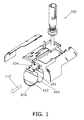
- FIG. 1 display an exploded view drawing of a barrier 100, in particular a barrier for rats, where the rodent may pass in a downstream flow direction (as indicated by arrow 112), but not in an upstream flow direction when the barrier is installed in the pipe.
- the shutters 101, 102 are mounted on a support element 104 and arranged in a manner so that they only may pivot in a downstream direction, such as pivot subject to influence of a force of a downstream flow.
- FIG. 1 furthermore shows that a profile, such as a second profile, of a part of an edge 416 of the second shutter 102 is toothed, and that a profile, such as a first profile, of a part of an edge 414 of the first shutter 101 is smooth.
- FIG. 1 shows an exploded view drawing of a barrier (100) suitable for installation at least partly in a sewage pipe (206, 208) and for allowing a sewage flow within the sewage pipe to pass the barrier in a first direction (212) of the sewage pipe, such as the first direction being a downstream direction, and for preventing rats (210) or other rodents from passing the barrier in a second direction being opposite to the first direction upon installation of the barrier in the sewage pipe, such as the second direction being an upstream direction, said barrier comprising
- FIG. 1 shows an exploded view drawing of a barrier 100 suitable for installation at least partly in a sewage pipe 206, 208 and for preventing rats 210 or other rodent from passing the barrier in at least one direction of the sewage pipe, such as at least in a second direction being and upstream direction, said barrier comprising
- the first shutter 101 and the second shutter 102 are arranged pivotably around each of their axes of rotation, and besides that they might touch each other when pivoting, they may pivot independently from each other.
- support structure 104 is shown in FIG. 1 as the plate immediately above the shutters, but it may in general be understood to be at least a portion of the barrier 100, besides the respective shutters 101, 102, on which the shutters are or may be mounted.
- an angular position of each of the first shutter and the second shutter may be changed subject to influence of the flow of water, such as a flow of water in a first direction, such as the first direction being a downstream direction, from the first angular position (v) to the second angular position (w),
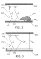
- FIG. 2 illustrates a barrier 100 installed in a sewage pipe with sewage pipe top 206 and sewage pipe bottom 208.
- the figure shows each of the first shutter 101 and second shutter 102 being in a first angular position (v) in which the shutter is forming a first relatively larger angle with a direction 212 of flow of sewage in the sewage pipe (note that dotted line 213 has been drawn so as to clearly indicate the direction of flow at the positions of the first and second shutters) and at least substantially barring, such as barring, an aperture of the barrier, such as barring the aperture so that a rat 210 cannot pass the barrier in an upstream direction, such as a second direction, such as a direction opposite the flow direction 212.
- the rat 210 attempting to pass the barrier 100 is likely to come into physical contact with at least a part of an edge of the second shutter 102, such as a part of the edge being a lower part of the edge with respect to gravity when the barrier is installed in a sewage pipe.
- FIG. 3 is similar to FIG. 2 except that it shows the second shutter 102 being in the second angular position (w) in which the shutter is forming a second relatively smaller angle with the direction of flow 212 in the sewage pipe keeping the aperture of the barrier at least partly open.
- the first shutter 101 is left in the first angular position, but in case both the first shutter 101 and the second shutter 102 are in the second angular position, the aperture of the barrier is at least partly open (with respect to both shutters), so as to enable a flow of liquid to pass the barrier.
- the figure furthermore shows a distance d b from a bottom 208 of the sewage pipe to a bottom of the first shutter 101.
- the figure furthermore shows a distance Dt from a top 206 of the sewage pipe to a bottom of the first shutter 101.
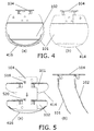
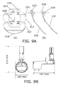
- FIG. 4 shows end views of a support element 104 and first 101 and second 102 shutters.
- FIG. 4(a) shows an end view as seen from a direction facing the second shutter 102. It is noted that the first shutter 101 is also visible behind the second shutter 102. It can be seen that at least a profile, such as a second profile, of a part of an edge 416 of the second shutter 102 is toothed, and that at least a profile, such as a first profile, of a part of an edge 414 of the first shutter 101 is smooth.
- FIG. 4(b) shows an end view as seen from a direction facing the first shutter 101.
- a first profile of at least a part of an edge 414 of the first shutter 101 is smoother than a second profile of a corresponding part of an edge 416 of the second shutter 102, so that
- FIG. 5 shows a top- and side view of a support element and 1 st and 2 nd shutters.
- FIG. 5(a) shows top view of the support element 104 and the first shutter 101 and the second shutter 102.
- the figure furthermore shows a first hole 518 in the support element 104, which hole is immediately above the first shutter 101, and a second hole 520 in the support element 104, which hole is immediately above the second shutter 102.
- FIG. 5(b) shows a side view of the support element 104, first shutter 101 and second shutter 102.
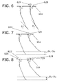
- FIGS. 6-8 shows side views of the support element 104, first shutter 101 and second shutter 102.
- FIG. 6 shows a side view of the support element 104, first shutter 101 and second shutter 102, where a second screw 624 is mounted in the second hole 520, but where the screw has not gone very far into the hole 520 as indicated by the large gap 628 between support element 104 and the head of the screw 624. Thus, a lower portion of the screw 624 does not touch the second shutter 102, which is left unaffected.
- FIG. 7 shows a side view corresponding to FIG. 6 , but where the second screw 624 is mounted in the second hole 520 and has gone further into the hole 520 as indicated by the large gap 729 (compared to the gap 628 in FIG. 7 ) between support element 104 and the head of the screw 624.
- a lower portion of the screw 624 does touch the second shutter 102, which cannot rotate as far clockwise as in FIG. 6 , so that the angle first angular position (v) of the second shutter 102 of FIG. 7 is adjusted compared to the first angular position (v) of the first shutter of FIG. 6 .
- FIG. 7 An effect of the adjusted angular position of the first angular position of the second shutter 102 is also indicated in FIG. 7 , where it can be seen that there is a difference D t1 -D t2 in vertical distance, cf., FIG. 3 , between a top of a pipe in which the barrier is installed and a lower portion of the second shutter 102 in
- a first angular position (v) of the second shutter 102 may be adjusted, wherein a vertical distance (Dt) from a top of the sewage pipe 206 to a bottom of the second shutter 102 in the first angular position (v) when the barrier 100 is installed in the sewage depends on said angle of the first angular position.
- FIG. 7 shows a side view corresponding to FIG. 7 , but where a first screw 822 is mounted in the first hole 518, but where the screw has not gone very far into the hole 518 as indicated by the large gap 826 between support element 104 and the head of the screw 822. Thus, a lower portion of the screw 822 does not touch the first shutter 101, which is left unaffected.
- FIG. 6 shows that a portion on a lower part of the first shutter 101 is bent in a direction corresponding to a direction of rotation from the first angular position (v) to the second angular position (w), cf. the angle (g), and that a portion on a lower part of the second shutter 102 is bent in the same direction, cf. the second angle (h), and that a first angle (g) which the lower portion of the first shutter 101 makes with horizontal when the first shutter is in the first angular position (v) is smaller than the second angle (h) which a lower portion of the second shutter 102 makes with horizontal when the second shutter is in the first angular position (v).
- first and/or the second shutter may be bowed instead of bent as shown in Figure 6 .
- the first and/or the second shutter may have a bowed shape, possibly including a bent structure so that the first and/or the second shutter may have a plurality of bowed sections.
- FIG. 9A shows a top- and side view of a support element and 1 st and 2 nd shutters, corresponding to FIG. 5 , but with a first screw 822 mounted in the first hole 518 and a second screw 624 mounted in the second hole so as to adjust an angle of the first angular position of each of the first and second shutters.
- FIG. 9B shows an end- and side view of the exemplary barrier of FIG. 1 , and indicates exemplary dimensions of the barrier.
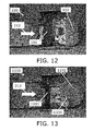
- FIGS. 10-17 show comparative photographs of various two tested barriers, which may be referred to as a barrier 100 according to an embodiment of the present invention, and a reference barrier 1100.
- the barrier 100 is a barrier as described in the FIGS. 1-9 .
- the reference barrier 1100 is similar to the barrier 100, except that the edges of both shutters are similar (both edges are toothed).
- the experiment was carried out by placing each barrier in a pipe adjacent to each their well in a test setup, where 4-6 litres of water is flushed through the barrier approximately once every 60 seconds.
- the water flows through the barrier and into a container which holds approximately 20 litres of water, and where a pump is arranged for pumping the 4-6 litres of water from the container and to the other side of the barrier so as to simulate a flush in a sewage pipe.
- a pump is arranged for pumping the 4-6 litres of water from the container and to the other side of the barrier so as to simulate a flush in a sewage pipe.
- To mimic the content of a sewage flow there is added approximately 15 pieces of leather (each piece being 5 cm x 10 cm) and pieces (cubes of 1.5 x 1.5 x 1.5 sq. cm) of vegetables (carrots and Brussels sprouts) are added throughout the experiment.
- the pipe is 110 mm in outer diameter.
- Both barrier 100 and reference barrier 1100 are mounted in the test setup for 14 days
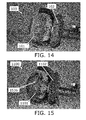
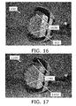
- FIGS. 10 , 12 , 14 , and 16 show the barrier 100 according to an embodiment of the invention.
- FIGS. 11 , 13 , 15 , 17 show the reference barrier 1100.
- the figures shows that both shutters, including the identical second shutters, have become dirtier during the experiment.
- the fact that the reference barrier 1100 attracts more dirt is a clear indication, that the barrier 100 is less prone to being blocked by dirty when installed in a sewage pipe.
- a front side of a shutter is referred to as a side, facing the flow direction, and a backside of a shutter is a side facing away from the flow direction.
- FIGS. 10-11 show the barriers from below with both shutters in the second angular position (barriers open).
- the figure clearly shows that the front sides and edges 414, 416 of both shutters 101, 102 in the barrier 100 is clear than the front sides and edges 1114, 1116 of both shutters 1101, 1102 in the reference barrier 1100.
- FIG. 11 shows that contamination 1130 is clearly present on a front side of the first shutter 1101 and that some solid material 1131, 1132 has stuck, respectively, to the edges 1114, 1116 of the shutters 1101, 1102 of the reference barrier 1100.
- FIG. 12-13 shows a similar result, where contamination 1334 is clearly visible on the front side of the second shutter 1102 of the reference barrier 1100, while the corresponding surface of the first shutter 101 in the barrier 100 is substantially clean. This may be seen as highly surprising, given that the second shutter 102 in the barrier 100 is identical to the second shutter 1102 in the reference barrier 1100.
- FIG. 14-15 shows a similar result, where contamination 1536 is clearly visible on the backside of first shutter 1101 of the reference barrier 1100, while the corresponding surface of the first shutter 101 in the barrier 100 is substantially clean.
- FIG. 16-17 shows a similar result, where contamination 1740 is clearly visible on the backside of second shutter 1102 of the reference barrier 1100, while the corresponding surface of the second shutter 102 in the barrier 100 is substantially clean.
- the visible matter 1638 is not solid matter, but is merely coloured foam, which - as opposed to contamination 1740 on the reference barrier - may for, example, easily be wiped off with a finger.
- a barrier (100) for installation at least partly in a sewage pipe (206, 208) and for preventing rats (210) or other rodent from passing the barrier in at least one direction of the sewage pipe, wherein the barrier comprises a support structure (104), a first shutter (101) and a second shutter (102) mounted on the support structure wherein a profile of at least a part of an edge of the first shutter is smoother than a profile of a corresponding part of an edge of the second shutter, such as a profile, such as a second profile, of a part of an edge (416) of the second shutter (102) is toothed, and that a profile, such as a first profile, of a part of an edge (414) of the first shutter (101) is smooth.
Abstract
Description
- The present invention relates to a rat barrier for installation in a sewage pipe, and more particularly a rat barrier with pivotally arranged shutters, use of such barrier and a pipe with such barrier.
- Barriers suitable for installation at least partly in a sewage pipe and for preventing rats or other rodents from passing the barrier in at least one direction of the sewage pipe are known in the art.
-
EP 2 113 615 relates to a barrier for preventing rats or other rodents from entering a sewage pipe. The barrier comprises a support element that is mountable within the pipe, and a first shutter pivotally suspended within the support element for rotation about a horizontal axis and having a centre of gravity lying under the axis. The shutter is pivotable between a first angular position in which the first shutter is forming an acute angle with the direction of flow and at least substantially barring the aperture of the barrier, and a second angular position in which the first shutter is forming a second relatively smaller angle with the direction of flow thus keeping the aperture of the barrier at least partly open. Preferably, a second shutter is placed upstream of a first shutter and is pivotally suspended about a second axis and having a centre of gravity located under the second axis. The first shutter can be suspended within the support element in two different orientations such that the direction in which the barrier blocks rodent from passing may be changed according to the needs without changing the orientation of the support element. - An improved barrier suitable for installation at least partly in a sewage pipe and for preventing rats or other rodents from passing the barrier in at least one direction of the sewage pipe would be advantageous, and in particular a more efficient and reliable barrier would be advantageous.
- In particular, it may be seen as an object of the present invention to provide a barrier suitable for installation at least partly in a sewage pipe and for preventing rats or other rodents from passing the barrier that may yield the mentioned advantages with respect to prior art barrier, such as being more reliable and/or efficient.
- It is a further object of the present invention to provide an alternative to the prior art.
- Thus, the above described object and several other objects are intended to be obtained in a first aspect of the invention by providing a barrier suitable for installation at least partly in a sewage pipe and for allowing a sewage flow within the sewage pipe to pass the barrier in a first direction of the sewage pipe, such as the first direction being a downstream direction, and for preventing rats or other rodents from passing the barrier in a second direction being opposite to the first direction upon installation of the barrier in the sewage pipe, such as the second direction being an upstream direction, said barrier comprising
- a support structure, such as a support structure comprising at least one hinge, such as a support structure comprising a first hinge and a second hinge,
- a first shutter pivotably mounted on the support structure, such as mounted on the first hinge, and
- a second shutter pivotably mounted on the support structure, such as mounted on the second hinge,
- the first shutter and the second shutter are spaced apart along the first direction so that the first shutter is placed before the second shutter on an axis parallel with the first direction, such as the first shutter being placed upstream with respect to the second shutter when the barrier is installed in the sewage pipe,
- The invention may be particularly, but not exclusively, advantageous for obtaining a barrier, which may be effective in preventing rats from passing the barrier in at least one direction, since an edge of the second shutter is less smooth than a corresponding edge of the first shutter, whereby the second shutter may therefore exert a greater sensory stimulus to a rat or other rodent which tries to pass the barrier. For example, a rat or other rodent trying to pass the barrier from the side facing the second shutter will have to be in physical contact with the edge of the second shutter, which second edge is less smooth than a corresponding edge of the first shutter, and which may therefore exert a greater sensory stimulus to the rat or other rodent, which may therefore give up and not pass the barrier.
- The invention may be particularly, but not exclusively, advantageous for obtaining a barrier, which may be more reliable, such as not being blocked by organic solid matter and other solid matter in, e.g., a sewage flow, since an edge of the first shutter is smoother than a corresponding edge of the second shutter, whereby the first shutter may therefore be less likely to attract organic solid matter and other solid matter in, e.g., a sewage flow, since such solid matter is less likely to get attached to, such as stick to, the smoother edge.
- The invention may be particularly, but not exclusively, advantageous for obtaining a barrier, which may be more reliable, such as not being blocked by organic solid matter and other solid matter in, e.g., a sewage flow, since an edge of the first shutter is smoother than a corresponding edge of the second shutter, which has the very surprising effect, that the second shutter may be less likely to attract organic solid matter and other solid matter in, e.g., a sewage flow.
- It may be seen as an insight of the present inventor, that a more reliable and efficient barrier may be achieved by having shutters with different degrees of smoothness, so as to enable both effective blocking of rats and other rodent, and enabling a reduction of risk of blocking of the barrier with solid organic waste and other solid material, and it may in particular be seen as an insight of the present inventor that a contamination of the second shutter may be reduced by changing the first shutter.
- A 'barrier' may be understood as is common in the art and described in, e.g., European
patent application EP 1 826 326 A1 and/orEP 2 113 615 B1 . - By 'suitable for installation at least partly in a sewage pipe' may be understood that the barrier may be positioned at least partially within a sewage pipe, such as partially within a sewage pipe and partially outside of a sewage pipe, such as partially in a well adjacent the sewage pipe, such as a completely inside a sewage pipe. The barrier may be located in a downstream sewage pipe to let rodents escape from a well and further away from housings. However, the barrier may also be used in an upstream sewage pipe so as to allow rats or other rodents to escape into a well and away from the upstream sewage pipe leading to, e.g. a housing.
- The barrier may be installed as described in, e.g., European
patent application EP 1 826 326 A1 which is hereby incorporated in their entirety. - A pipe may in general be understood to be any pipe, and in particular a sewage pipe, such as pipes for leading a sewage flow, such as any one of domestic sanitary, commercial, industrial, agricultural sewage flow and surface runoff.
- By 'allowing a sewage flow within the sewage pipe to pass the barrier in a first direction of the sewage pipe' may be understood, that a sewage flow may pass the barrier, such as the barrier being arranged so that the flow resistance of the barrier in the first direction is small enough so as to allow a sewage flow to pass. It may be understood that in an embodiment, a flow resistance of the barrier in the first direction is smaller than a flow resistance in the second direction.
- By 'preventing rats or other rodents from passing the barrier in a second direction' may be understood that the barrier may prevent rodent from passing the barrier in at least one direction, such as the second direction, such as an upstream direction. It may further be understood, that the barrier may not block rats or rodent from passing the barrier in the opposite direction, such as in the first direction, such as a downstream direction.
- It may be understood, that the barrier may be installed in a pipe so as to allow a flow of liquid in a first direction, such as a downstream direction, and so as to block rats or other rodents from passing the barrier in a second direction, such as an upstream direction. It may be understood, that the barrier may not necessarily block passage of rats or other rodents in a downstream direction.
- By 'first direction' may be understood a direction of flow of sewage in the sewage pipe, such as a downstream direction. While a pipe in itself may be symmetrical and as such not have any specific flow direction, it is in general understood, that a pipe, such as a sewage pipe, has a primary direction of flow, such as a direction of flow. The direction of flow may be the direction in which liquid typically flow through the pipe, such as due to gravity and/or pressure differences. By 'first direction' is understood at direction being parallel with a longitudinal direction of the sewage pipe in a direction being similar to a direction in which flow of sewage is allowed by the barrier, such as a downstream direction.
- By 'second direction' may be understood a direction in which rats or rodent are blocked. The second direction may be the upstream direction. By 'second direction' is understood at direction being parallel with a longitudinal direction of the sewage pipe in a direction being similar to a direction in which rats or other rodents are being prevented from passing the barrier, where the second direction is opposite to the first direction, such as the second direction being an upstream direction.
- By 'upstream direction' of a pipe may be understood a direction opposite the flow direction in the pipe.
- By 'downstream direction' of a pipe may be understood a direction of flow of liquid in the pipe.
- By 'a support structure' may be understood a structural part of the barrier in from which the shutters may be pivotally suspended. The support structure may comprise a part of the barrier not including the shutters or the entire barrier not including the shutters. It may be understood that the support structure may be structurally fixed to the sewage pipe, such as fixed via other structural elements in the barrier, such as fixed in an upper portion of the sewage pipe (with respect to gravity).
- By 'at least one hinge' may be understood at least a one hinge, such as a first hinge, such as a first hinge and a second hinge.
- A 'shutter' may be understood as is common in the art, such as described in, e.g., European
patent application EP 1 826 326 A1 and/orEP 2 113 615 B1 . In general, a shutter may thus denote a structural element, such as a plate or a net or a set of bars, which may be pivotally suspended so as to facilitate barring an aperture in a first angular position and not barring the aperture in a second angular position. - By 'first shutter' and 'second shutter' may be understood shutters which are placed relative to each other, so that in case the barrier is installed in a pipe so as to allow a flow of liquid in a first direction, such as a downstream direction, and so as to block rats or other rodents from passing the barrier in a second direction, such as an upstream direction, the first shutter is placed upstream relative to the second shutter. In other words, the first shutter is the first shutter, which the water passes when flowing through the pipe, pass the barrier in a downstream direction, and a rat or other rodent trying to pass the barrier in an upstream direction will first face the second shutter.
- The first shutter and the second shutter may be arranged pivotably around each of their axes of rotation. They may be arranged so as to enable each of them to pivot independently from each other, although they may touch each other for certain combinations of angular values.
- By a shutter being 'pivotably mounted on the support structure' may be understood that each shutter is linked to the support structure, and may each pivot around an axis of rotation, such as a hinge in the support structure. It is noted that the axis of rotation of the first shutter may or may not be identical to an axis of rotation of the second shutter. In a particular embodiment, the first and second shutters have spatially separated axes of rotation.
- By 'spaced apart along the first direction' may be understood that the first shutter and the second shutter are at different positions, and that these positions spaced apart along the first direction, such as along a direction parallel with the flow, such as the first shutter is placed at a first position with respect to the first direction, and the second shutter is placed at another position with respect to the first direction, such as further downstream. When referring to position of the first shutter or the second shutter, the position may be defined by the position of the centre of gravity of the respective shutter. An advantage of having the shutters spaced apart may be, that a rat or rodent trying to open the second shutter (where the second shutter may be the shutter the rat or rodent is facing when trying to pass the barrier in an upstream direction) by rotating it from the first angular position towards the second angular position, then the rat or rodent may have difficulties in handling the partially opened second shutter when it furthermore has to open the first shutter which is placed a little further upstream. The distance between the first shutter and the second shutter in the flow direction may be a distance arranged so as to be large enough that a rat or rodent cannot reach pass the second shutter and get hold of the first shutter and small enough that the rat or rodent cannot get pass, such as completely pass the second shutter, before having to open the first shutter. Said distance may be within 1-7 cm, such as 2-6 cm, such as 3-5 cm, such as substantially 4 cm, such as 4 cm. Said distance may advantageously be at least 30 mm. Said distance may advantageously be at most 50 mm. Said distance may be within 30-50 mm, such as 35 mm.
- A 'profile' may be understood as is common in the art, so as referring to an outline or contour. It may in the present context be understood, that shutters are generally flat, and that 'profile' refers to a profile of the edges of the generally flat shutters, such as the profile as observed in a direction orthogonal to a plane of the shutter.
- By 'at least a part of an edge' may be understood at least a part of an edge, such as at least a part of the edge of the first shutter or second shutter which - when the barrier is installed in a sewage pipe - would be accessible, such as immediately accessible, to rats or other rodents trying to pass the barrier and facing the shutter.
- By 'a profile of at least a part of an edge of the first shutter is smoother than a profile of a corresponding part of an edge of the second shutter' may be understood that a profile of at least a part of an edge, such as at least a part of the edge of the first shutter which - when the barrier is installed in a sewage pipe - would be accessible, such as immediately accessible, to rats or other rodents trying to pass the barrier and facing the shutter, is smoother than a profile of a corresponding part of an edge of the second shutter.
- By 'smoother' may be understood that topographical features on the edge of the first shutter, such as topographical features on the edge as observed from a direction away from the shutter where said direction is orthogonal to a plane of the shutter, may be larger and/or less smoothly than corresponding topographical features on the edge of the second shutter. When referring to degree of smoothness, it may be understood, to be smoothness on a length scale (such as 1 mm or 1 cm), which may be sensed by a rat or other rodent. It may be understood that an edge may be less smooth by comprising pointy features, such as having any one of a saw-toothed profile, a toothed profile, a serrated profile and/or notched profile. It may be understood that qualitatively similar edges, such as two toothed profiles, may differ in smoothness due to differences in quantitative measures, e.g., by differing in any one of amplitude (such as maximum height differences between maximum and minimum points of the profile), frequency and/or phase of teeth. It may be understood, that smoothness is to be understood to refer to a smoothness, which may be sensed by a rat or rodent upon touching said edge.
- The smoothness of a shutter may in a specific embodiment be quantified by the maximum distance between a line circumscribing the shutter and the largest distance between said line, such as 1 cm of said line being furthest from an axis of the pivotal mounting of said shutter, and the shutter. For example, for the shutters depicted in
Fig. 4 , said distance is approximately 0 mm for the first (smooth) shutter 101 (because the circumscribed line is in contact with the shutter at the bottom part as depicted inFig. 4 ), and approximately 3-7 mm, such as 5 mm for the second shutter (102) (corresponding to the height of the teeths at the bottom portion of the shutter in the figure, because the circumscribed line only touches the top parts of the teeths, and the distance is thus the distance from top to to bottom of teeths). The size of the shutters is presumed similar to the size given inFig. 9B . - By 'a part of the edge of the shutter which is immediately accessible to rats or other rodents trying to pass the barrier' may be understood a part of the edge which the rat may be most likely to touch upon, such as a part of the edge which the rat or rodent may reach, when being in front of the shutter, when the barrier is installed in a sewage pipe.
- It is noted that the barrier may be installed in a sewage pipe as described in any one of
EP 1 826 326 A2EP 2 113 615 A1 , which are both hereby incorporated by reference in entirety. It is furthermore noted, that said first shutter and second shutter may be capable of being positioned either in a first orientation in the barrier or in another orientation in the barrier, depending on the possible entering of the rodent, as described inEP 2 113 615 A1 , cf., e.g.,claim 1, which is hereby incorporated by reference in entirety. Particularly, the barrier according to the present invention may have a mounting mechanism comprising two wings, which each have a shape conforming to the sewage pipe interior, preferably the two wings has the shape of a part of the circumference of a circular pipe. The mounting mechanism may be expanded to establish a mounting of the barrier in the sewage pipe. Advantageously, the barrier may accordingly be mounted in standard circular pipes with various diameters because the barrier is insertable, at least partly, in such standard pipes. Additionally, the barrier is easy to replace and/or temporally remove for service and maintentence. - In an embodiment, such as a preferred embodiment, there is provided a barrier, wherein the barrier may be installed in a sewage pipe so that
- a. the first shutter is pivotally suspended from the support structure, such as about the first hinge, such as having a centre of gravity lying under an axis of rotation, and
- b. the second shutter is pivotally suspended from the support structure, such as about the second hinge, such as having a centre of gravity lying under an axis of rotation.
- In an embodiment, such as a preferred embodiment, there is provided a barrier, wherein the barrier may be installed in a sewage pipe so that each shutter within the group of shutters comprising the first shutter and the second shutter are pivotal between
- o a first angular position (v) in which the shutter is forming a first relatively larger angle with the first direction of the sewage pipe and at least substantially barring, such as barring, an aperture of the barrier, and
- o a second angular position (w) in which the shutter is forming a second relatively smaller angle with the first direction of the sewage pipe keeping the aperture of the barrier at least partly open, such as the first angular position and the second angular position being separated by less than 180 degrees.
- By 'wherein the barrier may be installed in a sewage pipe so that' may be understood that the claimed subject-matter is not confined to a barrier being installed in a sewage.
- By 'a first angular position (v) in which the shutter is forming a first relatively larger angle with a direction of flow of sewage in the sewage pipe' may be understood an angular position of the shutter, such as an angular position being defined by the angle the shutter makes with a direction of flow, such as an angle between
- a line through a main portion of the shutter (such as a centre of gravity) and the shutters axis of rotation, and
- a flow direction.
- It may be understood, that while "first angular position (v)" is employed for each of the first shutter and the second shutter, the angular value of said "first angular position (v)" for each of the first shutter and the second shutter need not necessarily be identical.
- By 'at least substantially barring, such as barring, an aperture of the barrier' may be understood barring an aperture of the barrier, such as enabling barrier access through a pipe in which the barrier is installed so as to enable preventing rats or other rodents from passing the barrier in at least one direction, such as an upstream direction.
- By 'a second angular position (w) in which the shutter is forming a second relatively smaller angle with the direction of flow of sewage in the sewage pipe, such as the first angular position and the second angular position being separated by less than 180 degrees,' may be understood an angular position of the shutter, such as an angular position being defined by the angle the shutter makes with a direction of flow, such as an angle between
- a line through a main portion of the shutter (such as a centre of gravity) and the shutters axis of rotation, and
- a flow direction.
- It may be understood, that while "second angular position (w)" is employed for each of the first shutter and the second shutter, the angular value of said "second angular position (w)" for each of the first shutter and the second shutter need not necessarily be identical.
- By 'keeping the aperture of the barrier at least partly open' may be understood as enabling a liquid flow, such as a flow of sewage, through a pipe in which the barrier is installed in at least one direction, such as a downstream direction, such as enabling a flow of sewage in a sewage pipe to pass the barrier.
- In an embodiment, such as a preferred embodiment, there is provided a barrier, wherein the barrier is arranged so as to prevent each of the first shutter and the second shutter from pivoting beyond the first angular position (v) in a rotational direction away from the second angular position (w), such as preventing rats or other rodents from passing the barrier in at least one direction, such as said at least one direction being a direction opposite a direction of flow of sewage in the sewage pipe.
- By 'so as to prevent each of the first shutter and the second shutter from pivoting beyond the first angular position (v) in a rotational direction away from the second angular position (w)' may be understood that when the barrier is installed the sewage pipe, then each of the first shutter and the second shutter may not be able to rotate further in a direction away from the second angular position than the first angular position. This may be beneficial for preventing rats or other rodents from passing the barrier in at least one direction, since they will have to open the shutters by rotating them towards themselves, since they cannot push them the other way (away from themselves). More particularly, the barrier may be configured to prevent the shutter from pivoting in an upstream direction (from the first angular position). This is relevant for preventing the rodent from passing the barrier in an upstream direction.
- In an embodiment, such as a preferred embodiment, there is provided a barrier, wherein the first shutter is placed relative to the second shutter, so that when the first shutter is in the first angular position and rotating towards the second position, then a point on the first shutter below a rotational axis of the first shutter will move in a direction substantially towards the second shutter, such as towards the second shutter.
- By 'wherein the first shutter is placed relative to the second shutter, so that when the first shutter is in the first angular position and rotating towards the second position, then a point on the first shutter below a rotational axis of the first shutter will move in a direction substantially towards the second shutter, such as towards the second shutter' may be understood that when the barrier is installed in, e.g., a sewage pipe, then the first shutter may be arranged so that when it is in the first angular position, such as substantially blocking the aperture of the barrier and pipe, then a lower portion of the first shutter may pivot towards the second shutter when the shutter pivots from a first angular position towards the second angular position. It may in general be understood, that the direction of rotation from the first angular position to the second angular position is similar for each of the first shutter and the second shutter.
- 'Rotational direction' may be understood as is known in the art, such as a direction of an angular rotation, such as clockwise or counterclockwise, as opposed to a translational (rectilinear) movement.
- By 'below' may be understood reference to a direction as defined by a direction of gravity.
- In an embodiment, such as a preferred embodiment, there is provided a barrier, wherein an angular position of each of the first shutter and the second shutter, such as when the barrier is installed in the sewage pipe, may be changed subject to influence of the flow of water, such as a flow of water in a first direction, such as the first direction being a downstream direction, from the first angular position (v) to the second angular position (w). By 'subject to influence of the flow of water' may be understood that the shutters are arranged in a manner so that they only may pivot in a direction caused by the force of a flow i.e. that the flow induces a force which causes the shutter, at least initially, to be be pivotally displaced. Notice that the barrier according to the present invention may therefore not be suitable for controlling the flow of sewage water itself.
- By 'shutter' may be understood a shutter having an spatial extension sufficient to not allowing a vermin, preferably a rat, to pass the barrier according to the present invention when the shutter is in the substantially vertical position in the corresponding sewage pipe i.e. in a closed position. Additionally, the shutter may have a spatial extension - in said closed position - that allows water to pass the barrier. Preferably, the shutter may have a wholly or partly circular shape allowing water to flow between the shutter and the sewage pipe i.e. at the periphery of the shutter when the shutter is in a said closed position. This is important in order not to obstructing the sewage water flow also at a relatively low flow of sewage water.
- The term 'rat or similar animals' may be understood to include at least the two main rat species known to live in populated areas; i.e. black rat (Rattus rattus) and brown rat (Rattus norvegicus), but the barrier according to the present invention may be applied for other rats species, and/or similar sized animals (e.g. other rodents) inhabiting sewage pipes and systems.
- An advantage of this embodiment may be that it enables a flow of liquid to open the barrier for itself, so as dispensing with a need for actively opening the barrier for allowing a flow of liquid to pass the barrier.
- In an embodiment, there is provided a barrier, wherein a profile of at least a part of an edge of the first shutter is smoother than a profile of a corresponding part of an edge of the second shutter,
so that - a force applied to a rat or other rodent via said part of an edge of the second shutter,
causes a greater sensory stimulus to a rat or other rodent, such as a rat or other rodent trying to pass the barrier, compared to - a force applied to a rat or another rodent via said part of an edge of the first shutter
- solid matter, such as solid organic waste and/or paper, in a flow of liquid in the sewage pipe being carried by the flow so as to touch said part of an edge of the second shutter,
would to a greater extent get attached to, such as stick to, said part of an edge compared to - solid matter, such as solid organic waste and/or paper, in a flow of liquid in the sewage pipe being carried by the flow so as to touch said part of an edge of the first shutter.
- By 'a force applied to a rat or other rodent via said part of an edge of the first shutter or the second shutter' may be understood a force applied to the rat via said part of an edge of the first shutter or the second shutter, such as said force being a contact force, such as said force being a contact force applied to said rat or other rodent in case said rat of rodent is trying to pass the barrier in the direction in which the barrier is preventing a rat or rodent from passing when said barrier is installed in a pipe.
- By 'causes a greater sensory stimulus to a rat or other rodent' may be understood that a rat or another rodent, such as a rat or other rodent trying to pass the barrier in the direction in which the barrier is preventing a rat or other rodent from passing when said barrier is installed in a pipe. The sensory stimulus may be understood to be as stimulus which is sensed by the rat or other rodent upon touching said part of an edge, such as applying a force to said part of an edge. The sensory stimulus may be understood as an unpleasant sensory stimulus, such as pain, such as an unpleasant sensory experience associated with actual or potential tissue damage, or described in terms of such damage. Said sensory stimulus may motivate the rat or other rodent to withdraw from its attempt to pass the barrier, so as to avoid the sensory stimulus, such as to avoid damaging a body part. The sensory stimulus may resolve promptly once the rat or other rodent withdraws from its attempt to pass the barrier.
- By 'upon installation in a sewage pipe' may be understood that the claimed subject-matter is not confined to a barrier being installed in a sewage.
- By 'solid matter' may be understood matter in a flow of liquid in a pipe, such as for example solid organic waste and/or paper.
- By 'in a flow of liquid in the sewage pipe being carried by the flow so as to touch said part of an edge of the first shutter and the second shutter' may be understood that solid material in a liquid in a pipe is carried by the liquid and may be carried by the liquid to the barrier so as to touch the barrier, such as said part on an edge of the respective shutters.
- By 'would to a greater extent get attached to, such as stick to, said part of an edge' may be understood that when solid matter, such as soft solid matter, such a soft organic solid matter, touches upon said part of an edge of the respective shutters, then said solid matter is more likely to get attached to, such as stick to, such as get caught by, a shutter where said part of an edge is less smooth, compared to a shutter where said part of an edge is smoother. This may be due to the solid matter better being able to getting caught by a less smooth edge.
- In an embodiment, there is provided a barrier, wherein said part of an edge of the second shutter has a profile being any one of
- a toothed profile, such as the toothed edge of the second shutter being more toothed than a corresponding edge of the first shutter,
- a serrated profile,
- a notched profile,
- a pointy profile,
- By 'pointy' may be understood a profile having pointy features, which may be felt by a rat or other rodent, such as felt as unpleasant.
- By 'smooth profile' may be understood that a circumscribed line around said part substantially corresponds, such as corresponds to a profile of said part. In general, and under practical circumstances, a smooth profile is understood to be a profile wherein any topographical features, if any, in the profile are either large compared to a rat or other rodent (so that said topographical features are substantially seen as a flat profile by the rat or other rodent) or small enough that the they are negligible compared to a size of a rodent (so that the rat or rodent may neglect them).
- In an embodiment, there is provided a barrier, wherein said part of an edge (416) of the second shutter (102) has a profile being
- a toothed profile,
- In an embodiment, there is provided a barrier, wherein the first shutter is arranged so as to guide solid matter in a flow of liquid in the sewage pipe in a direction from the first shutter to the second shutter, around the second shutter upon installation in a sewage pipe.
- By 'arranged so as to guide solid matter in a flow of liquid in the sewage pipe (in a direction from the first shutter to the second shutter) around the second shutter' may be understood that upon installation of said barrier in a sewage pipe, then - in a flow of liquid in a direction from the first shutter to the second shutter - any solid matter which flows through the barrier may be guided, such as guided by the relative size and shape of the first shutter and the second shutter, around the second shutter.
- An advantage of this may be that the second shutter is less likely to get dirty by contact with the solid matter. In particular, this may be seen as an advantage when at least a part of an edge of the first shutter is smoother than a corresponding part of an edge of the second shutter, since the less smooth edge of the second shutter would then be relatively more likely to attract the solid matter, unless the - relatively smooth - first shutter is arranged for guiding the solid matter around the second shutter.
- In an embodiment, there is provided a barrier,
wherein an area of a portion of the first shutter which may be in direct contact with a liquid flow during normal use is equal to or larger than an area of a portion of the second shutter which may be in direct contact with a liquid flow during normal use
and/or
wherein a circumscription around a portion of the first shutter which may be in direct contact with a liquid flow during normal use is equal to or larger than a circumscription around a portion of the second shutter which may be in direct contact with a liquid flow during normal use. - Since the level of liquid in a pipe, such as a sewage pipe, may typically be below a certain level, then typically only a portion of the barrier and shutters may be in contact with a liquid flow during normal use.
- By 'an area of a portion of the first shutter which may be in direct contact with a liquid flow during normal use' may be understood an area of the portion of the respective shutters which may be in contact with a liquid flow during normal use, such as a portion which is below said level.
- By 'a circumscription around a portion of the first shutter which may be in direct contact with a liquid flow during normal use' a circumscription around the portion of the respective shutters which may be in contact with a liquid flow during normal use, such as a portion which is below said level.
- An advantage of having said relation between said areas and/or said relation between said circumscriptions may be that these features may each alone or in combination be ways of achieving that the first shutter is arranged so as to guide solid matter in a flow of liquid in the sewage pipe in a direction from the first shutter to the second shutter, around the second shutter upon installation in a sewage pipe.
- In an embodiment, there is provided a barrier, wherein at least a portion on a lower part, such as a lower half part, such as a lower third part, such as a lower fourth part, such a lower fifth part, of the first shutter is bent in a direction corresponding to a direction of rotation from the first angular position to the second angular position, so as to reduce a damming of liquid in front of the barrier on the side facing the first shutter when the barrier is placed in a sewage pipe and a flow of liquid is passing in a direction from the first shutter to the second shutter. The said lower part of the first shutter is to be considered relative to an preferred mounting of the barrier where the support structure is oriented in upper part of the sewage pipe to enable better flow of liquid in the pipe, at least when the pipe is only partly filled with liquid flowing in the lower part of the pipe. Thus, the upper part of the shutter may considered the part closest to the supporting structure.
- By 'so as to reduce a damming' may be understood that said feature enables that for a given flow of liquid in a pipe upon installation of said barrier in the pipe, then a temporary rise in water level in front of the barrier, such as upstream of the barrier, may be lower.
- An advantage of this may be that a flow resistance through the barrier is smaller. Another advantage may be that the lower liquid level entails less contamination of the barrier, since floating solid matter in the liquid cannot contaminate relatively highly positioned parts of the barrier.
- In an embodiment, there is provided a barrier, wherein at least a portion on a lower part, such as a lower half part, such as a lower third part, such as a lower fourth part, such a lower fifth part, of the second shutter is bent in a direction corresponding to a direction of rotation from the first angular position to the second angular position, so as to reduce a damming of liquid in front of the barrier on the side facing the first shutter when the barrier is placed in a sewage pipe and a flow of liquid is passing in a direction from the first shutter to the second shutter. The said lower part of the second shutter is to be considered relative to an preferred mounting of the barrier where the support structure is oriented in upper part of the sewage pipe, at least when the pipe is only partly filled with liquid flowing in the lower part of the pipe. Thus, the upper part of the shutter may considered the part closest to the supporting structure.
- By 'so as to reduce a damming' may be understood that said feature enables that for a given flow of liquid in a pipe upon installation of said barrier in the pipe, then a temporary rise in water level in front of the barrier, such as upstream of the barrier, may be lower.
- An advantage of this may be that a flow resistance through the barrier is smaller. Another advantage may be that the lower liquid level entails less contamination of the barrier, since floating solid matter in the liquid cannot contaminate relatively highly positioned parts of the barrier.
- In an embodiment, there is provided a barrier, wherein
- a first angle which a lower portion of the first shutter makes with horizontal when the first shutter is in the first angular position (v),
- a second angle which a lower portion of the second shutter makes with horizontal when the second shutter is in the first angular position (v).
- An advantage of this may be that a flow of water in a direction from the first shutter towards the second shutter may relatively easily be opened by water, and when the shutters are placed relatively close to each other may then aid in opening the second shutter by directly touching upon the second shutter.
- In an embodiment, there is provided a barrier, wherein
- a position of the first shutter and/or a position of the second shutter may be adjusted,
- an angle, such as a primary angle, of the first angular position (v) of the first shutter and/or an angle, such as secondary angle, of the first angular position (v) of the second shutter may be adjusted,
- By 'a position of the first shutter and/or the second shutter' may be understood a position in the barrier, such as a position with respect to the sides, such as top and bottom, of the pipe, once installed in the pipe.
- By 'an angle of the first angular position (v) of the first shutter and/or an angle of the first angular position (v) of the second shutter' may be understood the angular value which the respective shutters have when installed in the barrier and being in the first angular position.
- An advantage of changing said position and/or angle may be that this enables changing a vertical distance from the sides of the pipe, such as the top and bottom of the pipe, to a bottom of the respective shutter, once the barrier is installed in the pipe. An advantage of this may in turn be that the barrier may be adapted to slightly varying inner pipe diameters.
- In an embodiment, there is provided a barrier, wherein the first angular position (v) may be adjusted, such as the barrier comprises means for enabling that the first angular position (v) may be adjusted.
- By 'means for enabling that the first angular position (v) may be adjusted' may be understood, e.g., one or more bolts or screws or studs, placed with respect to the shutter so as to change the angle of the angular position corresponding to the first angular position.
- In an embodiment, there is provided a barrier, wherein an angle of the first angular position of the first shutter and/or an angle of the first angular position (v) of the second shutter may be adjusted, such as the barrier comprises means for enabling that the first angular position (v) may be adjusted, wherein a vertical distance from a top of the sewage pipe to a bottom of the first shutter in the first angular position (v), respectively, the second shutter in the first angular position (v) when the barrier is installed in the sewage pipe depends on said angle .
- An advantage of this may be that different angles are appropriate for different flow rates, so adjusting the angle may be beneficial for optimizing the barrier with respect to an expected flow rate.
- According to a second aspect of the invention, there is presented a system comprising a pipe, such as a sewage pipe (206, 208), said pipe comprising barrier as defined in the first aspect, such as the barrier being arranged for preventing rats or other rodents from passing the barrier, such as preventing rats or other rodents from passing the barrier in at least one direction, such as at least in an upstream direction, such as allowing a flow of liquid in at least one direction, such as allowing a flow of liquid in at least a downstream direction.
- By 'pipe' may be understood any pipe, such as any one of a sewage pipe, such as pipes for leading a sewage flow, such as any one of domestic sanitary, commercial, industrial, agricultural sewage flow and surface runoff.
- According to a third aspect of the invention, there is presented use of a barrier according to the first aspect, for preventing rats or other rodents from passing the barrier, such as preventing rats or other rodents from passing the barrier in at least one direction in a pipe, such as a sewage pipe.
- According to a fourth aspect of the invention, there is presented a method for preventing rats or other rodents from passing through a pipe, such as a sewage pipe, such as preventing rats or other rodents from passing through a pipe in at least one direction in the pipe, such as at least in an upstream direction, said method comprising installing (such as installing as described in, e.g., any one of European
patent applications EP 1 826 326 A1 areEP 2 113 615 B1 which are each hereby incorporated in entirety) a barrier according to the first aspect in the pipe. - The first, second, third and fourth aspect of the present invention may each be combined with any of the other aspects. These and other aspects of the invention will be apparent from and elucidated with reference to the embodiments described hereinafter.
- In a first alternative aspect there is presented a as described in embodiment F1 below.
- Further embodiments according to the first alternative aspect is provided in embodiments F1-F12 below
- According to a second alternative aspect, there is presented a system according to embodiment F13 below.
- According to a third alternative aspect, there is presented use of a barrier according to embodiment F14 below.
- The first, second and third alternative aspect may each be combined with any of the other aspects. These and other aspects of the invention will be apparent from and elucidated with reference to the embodiments described hereinafter.
- The first, second, third and fourth aspects according to the invention will now be described in more detail with regard to the accompanying figures. The figures show one way of implementing the present invention and is not to be construed as being limiting to other possible embodiments falling within the scope of the attached claim set.
-
FIG. 1 shows an exemplary barrier according to an embodiment of the invention, -
FIGS. 2-3 shows a support element and first and second shutters in a pipe, -
FIG. 4 shows end views of a support element and first and second shutters, -
FIG. 5 shows a top- and side view of a support element and 1st and 2nd shutters, -
FIGS. 6-8 shows side views of first and second shutters, -
FIG. 9A shows a top- and side view of a support element and 1st and 2nd shutters, -
FIG. 9B shows an end- and side view of the exemplary barrier ofFIG. 1 , -
FIGS. 10-17 show comparative photographs of various two tested barriers. -
FIG. 1 display an exploded view drawing of abarrier 100, in particular a barrier for rats, where the rodent may pass in a downstream flow direction (as indicated by arrow 112), but not in an upstream flow direction when the barrier is installed in the pipe. Theshutters support element 104 and arranged in a manner so that they only may pivot in a downstream direction, such as pivot subject to influence of a force of a downstream flow.FIG. 1 furthermore shows that a profile, such as a second profile, of a part of anedge 416 of thesecond shutter 102 is toothed, and that a profile, such as a first profile, of a part of anedge 414 of thefirst shutter 101 is smooth. - More particularly,
FIG. 1 shows an exploded view drawing of a barrier (100) suitable for installation at least partly in a sewage pipe (206, 208) and for allowing a sewage flow within the sewage pipe to pass the barrier in a first direction (212) of the sewage pipe, such as the first direction being a downstream direction, and for preventing rats (210) or other rodents from passing the barrier in a second direction being opposite to the first direction upon installation of the barrier in the sewage pipe, such as the second direction being an upstream direction, said barrier comprising - a support structure (104), such as a support structure comprising at least one hinge, such as a support structure comprising a first hinge and a second hinge,
- a first shutter (101) pivotably mounted on the support structure, such as mounted on the first hinge, and
- a second shutter (102) pivotably mounted on the support structure, such as mounted on the second hinge,
- the first shutter (101) and the second shutter (102) are spaced apart along the first direction so that the first shutter is placed before the second shutter on an axis parallel with the first direction, such as the first shutter being placed upstream with respect to the second shutter when the barrier is installed in the sewage pipe,
- Still more particularly,
FIG. 1 shows an exploded view drawing of abarrier 100 suitable for installation at least partly in asewage pipe rats 210 or other rodent from passing the barrier in at least one direction of the sewage pipe, such as at least in a second direction being and upstream direction, said barrier comprising - a
support structure 104 comprising at least one hinge, such as a support structure comprising a first hinge and a second hinge, - a
first shutter 101 mounted on the support structure, such as mounted on the first hinge, and - a
second shutter 102 mounted on the support structure, such as mounted on the second hinge, - the
first shutter 101 is pivotally suspended from thesupport structure 104, such as about the first hinge, such as having a centre of gravity lying under an axis of rotation, and - the
second shutter 102 is pivotally suspended from thesupport structure 104, such as about the second hinge, such as having a centre of gravity lying under an axis of rotation, - a first angular position (v) in which the shutter is forming a first relatively larger angle with a
direction 212 of flow of sewage in the sewage pipe and at least substantially barring, such as barring, an aperture of the barrier, and - a second angular position (w) in which the shutter is forming a second relatively smaller angle with the direction of
flow 212 in the sewage pipe keeping the aperture of the barrier at least partly open, such as the first angular position and the second angular position being separated by less than 180 degrees, - the
first shutter 101 and thesecond shutter 102 are spaced apart in a direction parallel with adirection 212 of flow of sewage in the sewage pipe, - The
first shutter 101 and thesecond shutter 102 are arranged pivotably around each of their axes of rotation, and besides that they might touch each other when pivoting, they may pivot independently from each other. - It may be noted that
support structure 104 is shown inFIG. 1 as the plate immediately above the shutters, but it may in general be understood to be at least a portion of thebarrier 100, besides therespective shutters - In the present figure, an angular position of each of the first shutter and the second shutter, such as when the barrier is installed in the sewage pipe, may be changed subject to influence of the flow of water, such as a flow of water in a first direction, such as the first direction being a downstream direction, from the first angular position (v) to the second angular position (w),
-
FIG. 2 illustrates abarrier 100 installed in a sewage pipe withsewage pipe top 206 andsewage pipe bottom 208. For clarity, only thesupport element 104 andshutters FIG. 2 . The figure shows each of thefirst shutter 101 andsecond shutter 102 being in a first angular position (v) in which the shutter is forming a first relatively larger angle with adirection 212 of flow of sewage in the sewage pipe (note thatdotted line 213 has been drawn so as to clearly indicate the direction of flow at the positions of the first and second shutters) and at least substantially barring, such as barring, an aperture of the barrier, such as barring the aperture so that arat 210 cannot pass the barrier in an upstream direction, such as a second direction, such as a direction opposite theflow direction 212. - As indicated in
FIG. 2 , therat 210 attempting to pass thebarrier 100 is likely to come into physical contact with at least a part of an edge of thesecond shutter 102, such as a part of the edge being a lower part of the edge with respect to gravity when the barrier is installed in a sewage pipe. -
FIG. 3 is similar toFIG. 2 except that it shows thesecond shutter 102 being in the second angular position (w) in which the shutter is forming a second relatively smaller angle with the direction offlow 212 in the sewage pipe keeping the aperture of the barrier at least partly open. For the purpose of enabling a comparison, thefirst shutter 101 is left in the first angular position, but in case both thefirst shutter 101 and thesecond shutter 102 are in the second angular position, the aperture of the barrier is at least partly open (with respect to both shutters), so as to enable a flow of liquid to pass the barrier. - The figure furthermore shows a distance db from a
bottom 208 of the sewage pipe to a bottom of thefirst shutter 101. The figure furthermore shows a distance Dt from a top 206 of the sewage pipe to a bottom of thefirst shutter 101. -
FIG. 4 shows end views of asupport element 104 and first 101 and second 102 shutters. -
FIG. 4(a) shows an end view as seen from a direction facing thesecond shutter 102. It is noted that thefirst shutter 101 is also visible behind thesecond shutter 102. It can be seen that at least a profile, such as a second profile, of a part of anedge 416 of thesecond shutter 102 is toothed, and that at least a profile, such as a first profile, of a part of anedge 414 of thefirst shutter 101 is smooth. -
FIG. 4(b) shows an end view as seen from a direction facing thefirst shutter 101. - In the present figure, a first profile of at least a part of an
edge 414 of thefirst shutter 101 is smoother than a second profile of a corresponding part of anedge 416 of thesecond shutter 102, so that - a force applied to a
rat 210 or other rodent via said part of anedge 416 of the second shutter, - a force applied to a
rat 210 or another rodent via said part of anedge 414 of the first shutter -
solid matter 1131, such as solid organic waste and/or paper, in a flow of liquid in the sewage pipe being carried by the flow so as to touch said part of anedge 416 of thesecond shutter 102, - solid matter, such as solid organic waste and/or paper, in a flow of liquid in the sewage pipe being carried by the flow so as to touch said part of an
edge 414 of thefirst shutter 101. -
FIG. 5 shows a top- and side view of a support element and 1st and 2nd shutters. -
FIG. 5(a) shows top view of thesupport element 104 and thefirst shutter 101 and thesecond shutter 102. The figure furthermore shows afirst hole 518 in thesupport element 104, which hole is immediately above thefirst shutter 101, and asecond hole 520 in thesupport element 104, which hole is immediately above thesecond shutter 102.
FIG. 5(b) shows a side view of thesupport element 104,first shutter 101 andsecond shutter 102. -
FIGS. 6-8 shows side views of thesupport element 104,first shutter 101 andsecond shutter 102. -
FIG. 6 shows a side view of thesupport element 104,first shutter 101 andsecond shutter 102, where asecond screw 624 is mounted in thesecond hole 520, but where the screw has not gone very far into thehole 520 as indicated by thelarge gap 628 betweensupport element 104 and the head of thescrew 624. Thus, a lower portion of thescrew 624 does not touch thesecond shutter 102, which is left unaffected. -
FIG. 7 shows a side view corresponding toFIG. 6 , but where thesecond screw 624 is mounted in thesecond hole 520 and has gone further into thehole 520 as indicated by the large gap 729 (compared to thegap 628 inFIG. 7 ) betweensupport element 104 and the head of thescrew 624. Thus, a lower portion of thescrew 624 does touch thesecond shutter 102, which cannot rotate as far clockwise as inFIG. 6 , so that the angle first angular position (v) of thesecond shutter 102 ofFIG. 7 is adjusted compared to the first angular position (v) of the first shutter ofFIG. 6 . - An effect of the adjusted angular position of the first angular position of the
second shutter 102 is also indicated inFIG. 7 , where it can be seen that there is a difference Dt1-Dt2 in vertical distance, cf.,FIG. 3 , between a top of a pipe in which the barrier is installed and a lower portion of thesecond shutter 102 in - the first angular position of the
second shutter 102 as inFIG. 6 (or as the first angular position of thefirst shutter 101 as inFIG. 7 , which is shown for ease of comparison), and - the first angular position of the
second shutter 102 as inFIG. 7 . - Thus, the figure shows that a first angular position (v) of the
second shutter 102 may be adjusted, wherein a vertical distance (Dt) from a top of thesewage pipe 206 to a bottom of thesecond shutter 102 in the first angular position (v) when thebarrier 100 is installed in the sewage depends on said angle of the first angular position. -
FIG. 7 shows a side view corresponding toFIG. 7 , but where afirst screw 822 is mounted in thefirst hole 518, but where the screw has not gone very far into thehole 518 as indicated by thelarge gap 826 betweensupport element 104 and the head of thescrew 822. Thus, a lower portion of thescrew 822 does not touch thefirst shutter 101, which is left unaffected. - It may furthermore be noted that
FIG. 6 shows that a portion on a lower part of thefirst shutter 101 is bent in a direction corresponding to a direction of rotation from the first angular position (v) to the second angular position (w), cf. the angle (g), and that a portion on a lower part of thesecond shutter 102 is bent in the same direction, cf. the second angle (h), and that a first angle (g) which the lower portion of thefirst shutter 101 makes with horizontal when the first shutter is in the first angular position (v) is smaller than the second angle (h) which a lower portion of thesecond shutter 102 makes with horizontal when the second shutter is in the first angular position (v). Alternatively, the first and/or the second shutter may be bowed instead of bent as shown inFigure 6 . More alternatively, e the first and/or the second shutter may have a bowed shape, possibly including a bent structure so that the first and/or the second shutter may have a plurality of bowed sections. -
FIG. 9A shows a top- and side view of a support element and 1st and 2nd shutters, corresponding toFIG. 5 , but with afirst screw 822 mounted in thefirst hole 518 and asecond screw 624 mounted in the second hole so as to adjust an angle of the first angular position of each of the first and second shutters. -
FIG. 9B shows an end- and side view of the exemplary barrier ofFIG. 1 , and indicates exemplary dimensions of the barrier. -
FIGS. 10-17 show comparative photographs of various two tested barriers, which may be referred to as abarrier 100 according to an embodiment of the present invention, and areference barrier 1100. Thebarrier 100 is a barrier as described in theFIGS. 1-9 . Thereference barrier 1100 is similar to thebarrier 100, except that the edges of both shutters are similar (both edges are toothed). - The experiment was carried out by placing each barrier in a pipe adjacent to each their well in a test setup, where 4-6 litres of water is flushed through the barrier approximately once every 60 seconds. The water flows through the barrier and into a container which holds approximately 20 litres of water, and where a pump is arranged for pumping the 4-6 litres of water from the container and to the other side of the barrier so as to simulate a flush in a sewage pipe. To mimic the content of a sewage flow, there is added approximately 15 pieces of leather (each piece being 5 cm x 10 cm) and pieces (cubes of 1.5 x 1.5 x 1.5 sq. cm) of vegetables (carrots and Brussels sprouts) are added throughout the experiment. The pipe is 110 mm in outer diameter. Both
barrier 100 andreference barrier 1100 are mounted in the test setup for 14 days. The experiment lasts for these 14 days, and the flushing is repeated approximately each 60 seconds in the period 8.00-23.00 (i.e., for 15 hours each day). -
FIGS. 10 ,12 ,14 , and16 show thebarrier 100 according to an embodiment of the invention.FIGS. 11 ,13 ,15 ,17 show thereference barrier 1100. In general, the figures shows that both shutters, including the identical second shutters, have become dirtier during the experiment. The fact that thereference barrier 1100 attracts more dirt is a clear indication, that thebarrier 100 is less prone to being blocked by dirty when installed in a sewage pipe. - In the following figures a front side of a shutter is referred to as a side, facing the flow direction, and a backside of a shutter is a side facing away from the flow direction.
-
FIGS. 10-11 show the barriers from below with both shutters in the second angular position (barriers open). The figure clearly shows that the front sides andedges shutters barrier 100 is clear than the front sides andedges shutters reference barrier 1100. In particular, while front sides and edges of theshutters barrier 100 inFIG. 10 are substantially clean.FIG. 11 , on the other hand, shows thatcontamination 1130 is clearly present on a front side of thefirst shutter 1101 and that somesolid material edges shutters reference barrier 1100. -
FIG. 12-13 shows a similar result, wherecontamination 1334 is clearly visible on the front side of thesecond shutter 1102 of thereference barrier 1100, while the corresponding surface of thefirst shutter 101 in thebarrier 100 is substantially clean. This may be seen as highly surprising, given that thesecond shutter 102 in thebarrier 100 is identical to thesecond shutter 1102 in thereference barrier 1100. -
FIG. 14-15 shows a similar result, wherecontamination 1536 is clearly visible on the backside offirst shutter 1101 of thereference barrier 1100, while the corresponding surface of thefirst shutter 101 in thebarrier 100 is substantially clean. -
FIG. 16-17 shows a similar result, wherecontamination 1740 is clearly visible on the backside ofsecond shutter 1102 of thereference barrier 1100, while the corresponding surface of thesecond shutter 102 in thebarrier 100 is substantially clean. It is noted that thevisible matter 1638 is not solid matter, but is merely coloured foam, which - as opposed tocontamination 1740 on the reference barrier - may for, example, easily be wiped off with a finger. - To sum up, there is presented a barrier (100) for installation at least partly in a sewage pipe (206, 208) and for preventing rats (210) or other rodent from passing the barrier in at least one direction of the sewage pipe, wherein the barrier comprises a support structure (104), a first shutter (101) and a second shutter (102) mounted on the support structure wherein a profile of at least a part of an edge of the first shutter is smoother than a profile of a corresponding part of an edge of the second shutter, such as a profile, such as a second profile, of a part of an edge (416) of the second shutter (102) is toothed, and that a profile, such as a first profile, of a part of an edge (414) of the first shutter (101) is smooth.
- In embodiments E1-E19 of the invention, there is presented:
- E1. A barrier (100) suitable for installation at least partly in a sewage pipe (206, 208) and for allowing a sewage flow within the sewage pipe to pass the barrier in a first direction (212) of the sewage pipe, such as the first direction being a downstream direction, and for preventing rats (210) or other rodents from passing the barrier in a second direction being opposite to the first direction upon installation of the barrier in the sewage pipe, such as the second direction being an upstream direction, said barrier comprising
- a support structure (104), such as a support structure comprising at least one hinge, such as a support structure comprising a first hinge and a second hinge,
- a first shutter (101) pivotably mounted on the support structure, such as mounted on the first hinge, and
- a second shutter (102) pivotably mounted on the support structure, such as mounted on the second hinge,
- the first shutter (101) and the second shutter (102) are spaced apart along the first direction so that the first shutter is placed before the second shutter on an axis parallel with the first direction, such as the first shutter being placed upstream with respect to the second shutter when the barrier is installed in the sewage pipe,
a profile of at least a part of an edge of the first shutter is smoother than a profile of a corresponding part of an edge of the second shutter, such as the corresponding part of an edge of the second shutter being a part of the edge of the second shutter which is immediately accessible to rats or other rodents trying to pass the barrier from the side facing the second shutter. - E2. A barrier (100) as defined in any of the preceding embodiments, wherein the barrier (100) may be installed in a sewage pipe so that
- a. the first shutter (101) is pivotally suspended from the support structure (104), such as about the first hinge, such as having a centre of gravity lying under an axis of rotation, and
- b. the second shutter (102) is pivotally suspended from the support structure (104), such as about the second hinge, such as having a centre of gravity lying under an axis of rotation.
- E3. A barrier (100) as defined in any of the preceding embodiments, wherein the barrier (100) may be installed in a sewage pipe so that each shutter within the group of shutters comprising the first shutter (101) and the second shutter (102) are pivotal between
- o a first angular position (v) in which the shutter is forming a first relatively larger angle with the first direction (212) of the sewage pipe and at least substantially barring, such as barring, an aperture of the barrier, and
- o a second angular position (w) in which the shutter is forming a second relatively smaller angle with the first direction (212) of the sewage pipe keeping the aperture of the barrier at least partly open, such as the first angular position and the second angular position being separated by less than 180 degrees.
- E4. A barrier (100) as defined in any of the preceding embodiments, wherein the barrier is arranged so as to prevent each of the first shutter (101) and the second shutter (102) from pivoting beyond the first angular position (v) in a rotational direction away from the second angular position (w), such as preventing rats or other rodents from passing the barrier in at least one direction, such as said at least one direction being a direction opposite a direction of flow of sewage in the sewage pipe.
- E5. A barrier (100) as defined in any of the preceding embodiments, wherein the first shutter (101) is placed relative to the second shutter (102), so that when the first shutter is in the first angular position and rotating towards the second position, then a point on the first shutter below a rotational axis of the first shutter will move in a direction substantially towards the second shutter, such as towards the second shutter.
- E6. A barrier (100) as defined in any of the preceding embodiments an wherein angular position of each of the first shutter and the second shutter, such as when the barrier is installed in the sewage pipe, may be changed subject to influence of the flow of water, such as a flow of water in a first direction, such as the first direction being a downstream direction, from the first angular position (v) to the second angular position (w).
- E7. A barrier (100) as defined in any of the preceding embodiments, wherein a first profile of at least a part of an edge (414) of the first shutter (101) is smoother than a second profile of a corresponding part of an edge (416) of the second shutter (102),
so that- a force applied to a rat (210) or other rodent via said part of an edge (416) of the second shutter,
- a force applied to a rat (210) or another rodent via said part of an edge (414) of the first shutter
- solid matter (1131), such as solid organic waste and/or paper, in a flow of liquid in the sewage pipe being carried by the flow so as to touch said part of an edge (416) of the second shutter (102),
- solid matter, such as solid organic waste and/or paper, in a flow of liquid in the sewage pipe being carried by the flow so as to touch said part of an edge (414) of the first shutter (101).
- E8. A barrier (100) as defined in any of the preceding embodiments, wherein said part of an edge (416) of the second shutter (102) has a profile being any one of
- a toothed profile, such as the toothed edge of the second shutter being more toothed than a corresponding edge of the first shutter,
- a serrated profile,
- a notched profile,
- a pointy profile,
- E9. A barrier (100) as defined in any of the preceding embodiments, wherein the first shutter (101) is arranged so as to guide solid matter in a flow of liquid in the sewage pipe in a direction from the first shutter (101) to the second shutter (102), around the second shutter upon installation in a sewage pipe.
- E10. A barrier (100) as defined in any of the preceding embodiments,
wherein an area of a portion of the first shutter (101) which may be in direct contact with a liquid flow during normal use is equal to or larger than an area of a portion of the second shutter (102) which may be in direct contact with a liquid flow during normal use
and/or
wherein a circumscription around a portion of the first shutter (101) which may be in direct contact with a liquid flow during normal use is equal to or larger than a circumscription around a portion of the second shutter (102) which may be in direct contact with a liquid flow during normal use. - E11. A barrier (100) as defined in any of the preceding embodiments, wherein at least a portion on a lower part, such as a lower half part, such as a lower third part, such as a lower fourth part, such a lower fifth part, of the first shutter (101) is bent in a direction corresponding to a direction of rotation from the first angular position (v) to the second angular position (w), so as to reduce a damming of liquid in front of the barrier on the side facing the first shutter when the barrier is placed in a sewage pipe and a flow of liquid is passing in a direction from the first shutter to the second shutter.
- E12. A barrier (100) as defined in any of the preceding embodiments, wherein at least a portion on a lower part, such as a lower half part, such as a lower third part, such as a lower fourth part, such a lower fifth part, of the second shutter (102) is bent in a direction corresponding to a direction of rotation from the first angular position (v) to the second angular position (w), so as to reduce a damming of liquid in front of the barrier on the side facing the first shutter when the barrier is placed in a sewage pipe and a flow of liquid is passing in a direction from the first shutter to the second shutter.
- E13. A barrier (100) as defined in any of the preceding embodiments, wherein
- o a first angle (g) which a lower portion of the first shutter (101) makes with horizontal when the first shutter is in the first angular position (v),
- o a second angle (h) which a lower portion of the second shutter (102) makes with horizontal when the second shutter is in the first angular position (v).
- E14. A barrier (100) as defined in any of the preceding embodiments, wherein
- a position of the first shutter (101) and/or a position of the second shutter (102) may be adjusted,
- an angle of the first angular position (v) of the first shutter and/or an angle of the first angular position (v) of the second shutter may be adjusted,
- E15. A barrier (100) as defined in any of the preceding embodiments, wherein the first angular position (v) may be adjusted, such as the barrier comprises means for enabling that the first angular position (v) may be adjusted.
- E16. A barrier (100) as defined in any of the preceding embodiments, wherein an angle of the first angular position of the first shutter (101) and/or an angle of the first angular position (v) of the second shutter (102) may be adjusted, such as the barrier comprises means for enabling that the first angular position (v) may be adjusted, wherein a vertical distance (Dt) from a top of the sewage pipe (206) to a bottom of the first shutter (101) in the first angular position (v), respectively, the second shutter (102) in the first angular position (v), when the barrier is installed in the sewage pipe depends on said angle.
- E17. A system comprising a pipe, such as a sewage pipe (206, 208), said pipe comprising a barrier (100) as defined in any one of the preceding embodiments, such as the barrier being arranged for preventing rats or other rodents from passing the barrier, such as preventing rats or other rodents from passing the barrier in at least one direction, such as at least in an upstream direction, such as allowing a flow of liquid in at least one direction, such as allowing a flow of liquid in at least a downstream direction.
- E18. Use of a barrier (100) according to any of the preceding embodiments E1-E16, for preventing rats or other rodents from passing the barrier, such as preventing rats or other rodents from passing the barrier in at least one direction in a pipe, such as a sewage pipe.
- E19. A method for preventing rats or other rodents from passing through a pipe, such as a sewage pipe, such as preventing rats or other rodents from passing through a pipe in at least one direction in the pipe, such as at least in an upstream direction, said method comprising installing a barrier (100) according to any of the preceding embodiments E1-E16 in the pipe.
- For the above embodiments E1-E19, it may be understood that reference to preceding 'embodiments' may in particular refer to preceding embodiments within embodiments E1-E19.
- Although the present invention has been described in connection with the specified embodiments, it should not be construed as being in any way limited to the presented examples. The scope of the present invention is set out by the accompanying claim set. In the context of the claims, the terms "comprising" or "comprises" do not exclude other possible elements or steps. Also, the mentioning of references such as "a" or "an" etc. should not be construed as excluding a plurality. The use of reference signs in the claims with respect to elements indicated in the figures shall also not be construed as limiting the scope of the invention. Furthermore, individual features mentioned in different claims, may possibly be advantageously combined, and the mentioning of these features in different claims does not exclude that a combination of features is not possible and advantageous.
- In alternative embodiments F1-F15, there is presented:
- F1. A barrier (100) suitable for installation at least partly in a sewage pipe (206, 208) and for allowing a sewage flow within the sewage pipe to pass the barrier in a first direction (212) of the sewage pipe, such as the first direction being a downstream direction, and for preventing rats (210) or other rodents from passing the barrier in a second direction being opposite to the first direction upon installation of the barrier in the sewage pipe, such as the second direction being an upstream direction, said barrier comprising
- a support structure (104), such as a support structure comprising at least one hinge, such as a support structure comprising a first hinge and a second hinge,
- a first shutter (101) pivotably mounted on the support structure, such as mounted on the first hinge, and
- an optional second shutter (102) pivotably mounted on the support structure, such as mounted on the second hinge.
- the first shutter (101) and the second shutter (102) are spaced apart along the first direction so that the first shutter is placed before the second shutter on an axis parallel with the first direction, such as the first shutter being placed upstream with respect to the second shutter when the barrier is installed in the sewage pipe,
- a position of the first shutter (101) and/or a position of the second shutter (102) may be adjusted,
- an angle of the first angular position (v) of the first shutter and/or an angle of the first angular position (v) of the second shutter may be adjusted,
- F2. A barrier (100) as defined in any of the preceding embodiments, wherein the barrier comprises the second shutter (102) and wherein the barrier is arranged for being installed in the sewage pipe so that
- the first shutter (101) and the second shutter (102) are spaced apart along the first direction so that the first shutter is placed before the second shutter on an axis parallel with the first direction, such as the first shutter being placed upstream with respect to the second shutter when the barrier is installed in the sewage pipe.
- F3. A barrier (100) as defined in any of the preceding embodiments, wherein the barrier (100) may be installed in a sewage pipe so that
- a. the first shutter (101) is pivotally suspended from the support structure (104), such as about the first hinge, such as having a centre of gravity lying under an axis of rotation, and
- b. the optional second shutter (102) is pivotally suspended from the support structure (104), such as about the second hinge, such as having a centre of gravity lying under an axis of rotation.
- F4. A barrier (100) as defined in any of the preceding embodiments, wherein the barrier (100) may be installed in a sewage pipe so that each shutter within the group of shutters comprising the first shutter (101) and the optional second shutter (102) are pivotal between
- ∘ a first angular position (v) in which the shutter is forming a first relatively larger angle with the first direction (212) of the sewage pipe and at least substantially barring, such as barring, an aperture of the barrier, and
- ∘ a second angular position (w) in which the shutter is forming a second relatively smaller angle with the first direction (212) of the sewage pipe keeping the aperture of the barrier at least partly open, such as the first angular position and the second angular position being separated by less than 180 degrees.
- F5. A barrier (100) as defined in any of the preceding embodiments, wherein the barrier is arranged so as to prevent each of the first shutter (101) and the optional second shutter (102) from pivoting beyond the first angular position (v) in a rotational direction away from the second angular position (w), such as preventing rats or other rodents from passing the barrier in at least one direction, such as said at least one direction being a direction opposite a direction of flow of sewage in the sewage pipe.
- F6. A barrier (100) as defined in any of the preceding embodiments, wherein the barrier comprises the second shutter (102), and wherein the first shutter (101) is placed relative to the second shutter (102), so that when the first shutter is in the first angular position and rotating towards the second position, then a point on the first shutter below a rotational axis of the first shutter will move in a direction substantially towards the second shutter, such as towards the second shutter.
- F7. A barrier (100) as defined in any of the preceding embodiments wherein an angular position of each of the first shutter and the second shutter, such as when the barrier is installed in the sewage pipe, may be changed subject to influence of the flow of water, such as a flow of water in a first direction, such as the first direction being a downstream direction, from the first angular position (v) to the second angular position (w).
- F8. A barrier (100) as defined in any of the preceding embodiments, wherein the first shutter (101) is arranged so as to guide solid matter in a flow of liquid in the sewage pipe in a direction from the first shutter (101) to the second shutter (102), around the second shutter upon installation in a sewage pipe.
- F9. A barrier (100) as defined in any of the preceding embodiments,
wherein an area of a portion of the first shutter (101) which may be in direct contact with a liquid flow during normal use is equal to or larger than an area of a portion of the second shutter (102) which may be in direct contact with a liquid flow during normal use
and/or
wherein a circumscription around a portion of the first shutter (101) which may be in direct contact with a liquid flow during normal use is equal to or larger than a circumscription around a portion of the second shutter (102) which may be in direct contact with a liquid flow during normal use. - F10. A barrier (100) as defined in any of the preceding embodiments, wherein at least a portion on a lower part, such as a lower half part, such as a lower third part, such as a lower fourth part, such a lower fifth part, of the first shutter (101) is bent in a direction corresponding to a direction of rotation from the first angular position (v) to the second angular position (w), so as to reduce a damming of liquid in front of the barrier on the side facing the first shutter when the barrier is placed in a sewage pipe and a flow of liquid is passing in a direction from the first shutter to the second shutter.
- F11. A barrier (100) as defined in any of the preceding embodiments, wherein at least a portion on a lower part, such as a lower half part, such as a lower third part, such as a lower fourth part, such a lower fifth part, of the second shutter (102) is bent in a direction corresponding to a direction of rotation from the first angular position (v) to the second angular position (w), so as to reduce a damming of liquid in front of the barrier on the side facing the first shutter when the barrier is placed in a sewage pipe and a flow of liquid is passing in a direction from the first shutter to the second shutter.
- F12. A barrier (100) as defined in any of the preceding embodiments, wherein
- a first angle (g) which a lower portion of the first shutter (101) makes with horizontal when the first shutter is in the first angular position (v), is smaller than
- a second angle (h) which a lower portion of the second shutter (102) makes with horizontal when the second shutter is in the first angular position (v).
- F13. A system comprising a pipe, such as a sewage pipe (206, 208), said pipe comprising a barrier (100) as defined in any one of the preceding embodiments, such as the barrier being arranged for preventing rats or other rodents from passing the barrier, such as preventing rats or other rodents from passing the barrier in at least one direction, such as at least in an upstream direction, such as allowing a flow of liquid in at least one direction, such as allowing a flow of liquid in at least a downstream direction.
- F14. Use of a barrier (100) according to any of the preceding embodiments F1-F12, for preventing rats or other rodents from passing the barrier, such as preventing rats or other rodents from passing the barrier in at least one direction in a pipe, such as a sewage pipe.
- F15. A method for preventing rats or other rodents from passing through a pipe, such as a sewage pipe, such as preventing rats or other rodents from passing through a pipe in at least one direction in the pipe, such as at least in an upstream direction, said method comprising installing a barrier (100) according to any of the preceding embodiments F1-F12 in the pipe.
- For the above embodiments F1-F15, it may be understood that reference to preceding 'embodiments' may refer to preceding embodiments within embodiments F1-F15.
a profile of at least a part of an edge of the first shutter is smoother than a profile of a corresponding part of an edge of the second shutter, such as the corresponding part of an edge of the second shutter being a part of the edge of the second shutter which is immediately accessible to rats or other rodents trying to pass the barrier from the side facing the second shutter.
By 'toothed' may be understood having teeth, where teeth are understood as topographical features, such as topographical features which may be felt by a rat or other rodent, such as felt as unpleasant. The teeth may be pointy and have similar of dissimilar shape, and may for example be triangular.
wherein the
wherein
a profile of at least a part of an edge of the first shutter is smoother than a profile of a corresponding part of an edge of the second shutter, such as the corresponding part of an edge of the second shutter being a part of the edge of the second shutter which is immediately accessible to rats or other rodents trying to pass the barrier from the side facing the second shutter.
Claims (15)
- A barrier (100) suitable for installation at least partly in a sewage pipe (206, 208) and for allowing a sewage flow within the sewage pipe to pass the barrier in a first direction (212) of the sewage pipe, such as the first direction being a downstream direction, and for preventing rats (210) or other rodents from passing the barrier in a second direction being opposite to the first direction upon installation of the barrier in the sewage pipe, such as the second direction being an upstream direction, said barrier comprising- a support structure (104), such as a support structure comprising at least one hinge, such as a support structure comprising a first hinge and a second hinge,- a first shutter (101) pivotably mounted on the support structure, such as mounted on the first hinge, and- a second shutter (102) pivotably mounted on the support structure, such as mounted on the second hinge,wherein the barrier is arranged for being installed in the sewage pipe so that- the first shutter (101) and the second shutter (102) are spaced apart along the first direction so that the first shutter is placed before the second shutter on an axis parallel with the first direction, such as the first shutter being placed upstream with respect to the second shutter when the barrier is installed in the sewage pipe,wherein
a profile of at least a part of an edge of the first shutter is smoother than a profile of a corresponding part of an edge of the second shutter, such as the corresponding part of an edge of the second shutter being a part of the edge of the second shutter which is immediately accessible to rats or other rodents trying to pass the barrier from the side facing the second shutter. - A barrier (100) as defined in claim 1, wherein a first profile of at least a part of an edge (414) of the first shutter (101) is smoother than a second profile of a corresponding part of an edge (416) of the second shutter (102),
so that- a force applied to a rat (210) or other rodent via said part of an edge (416) of the second shutter,causes a greater sensory stimulus to a rat or other rodent, such as a rat or other rodent trying to pass the barrier, compared to- a force applied to a rat (210) or another rodent via said part of an edge (414) of the first shutterand/or so that upon installation in a sewage pipe- solid matter (1131), such as solid organic waste and/or paper, in a flow of liquid in the sewage pipe being carried by the flow so as to touch said part of an edge (416) of the second shutter (102),would to a greater extent get attached to, such as stick to, said part of an edge compared to- solid matter, such as solid organic waste and/or paper, in a flow of liquid in the sewage pipe being carried by the flow so as to touch said part of an edge (414) of the first shutter (101). - A barrier (100) as defined in any of the preceding claims, wherein said part of an edge (416) of the second shutter (102) has a profile being any one of- a toothed profile, such as the toothed edge of the second shutter being more toothed than a corresponding edge of the first shutter,- a serrated profile,- a notched profile,- a pointy profile,and/or wherein said part of an edge (414) of the first shutter (101) has as a profile being a substantially smooth profile, such as a smooth profile.
- A barrier (100) as defined in any claims 1-2, wherein said part of an edge (416) of the second shutter (102) has a profile being- a toothed profile,and/or wherein said part of an edge (414) of the first shutter (101) has as a profile being a smooth profile.
- A barrier (100) as defined in any of the preceding claims, wherein the first shutter (101) is arranged so as to guide solid matter in a flow of liquid in the sewage pipe in a direction from the first shutter (101) to the second shutter (102), around the second shutter upon installation in a sewage pipe.
- A barrier (100) as defined in any of the preceding claims, wherein at least a portion on a lower part, such as a lower half part, such as a lower third part, such as a lower fourth part, such a lower fifth part, of the first shutter (101) is bent in a direction corresponding to a direction of rotation from the first angular position (v) to the second angular position (w), so as to reduce a damming of liquid in front of the barrier on the side facing the first shutter when the barrier is placed in a sewage pipe and a flow of liquid is passing in a direction from the first shutter to the second shutter.
- A barrier (100) as defined in any of the preceding claims, wherein an area of a portion of the first shutter (101) which may be in direct contact with a liquid flow during normal use is equal to or larger than an area of a portion of the second shutter (102) which may be in direct contact with a liquid flow during normal use.
- A barrier (100) as defined in any of the preceding claims, wherein a circumscription around a portion of the first shutter (101) which may be in direct contact with a liquid flow during normal use is equal to or larger than a circumscription around a portion of the second shutter (102) which may be in direct contact with a liquid flow during normal use.
- A barrier (100) as defined in any of the preceding claims, wherein- a first angle (g) which a lower portion of the first shutter (101) makes with horizontal when the first shutter is in the first angular position (v),is smaller than- a second angle (h) which a lower portion of the second shutter (102) makes with horizontal when the second shutter is in the first angular position (v).
- A barrier (100) as defined in any of the preceding claims, wherein- a position of the first shutter (101) and/or a position of the second shutter (102) may be adjusted,and/or wherein- an angle of the first angular position (v) of the first shutter and/or an angle of the first angular position (v) of the second shutter may be adjusted,wherein a vertical distance (Dt) from a top of the sewage pipe (206) to a bottom of the first shutter (101) in the first angular position (v), respectively, the second shutter (102) in the first angular position (v), when the barrier (100) is installed in the sewage pipe depends on said position and/or said angle of the first angular position.
- A barrier (100) as defined in any of the preceding claims, wherein the first angular position (v) may be adjusted, such as the barrier comprises means for enabling that the first angular position (v) may be adjusted.
- A barrier (100) as defined in any of the preceding claims, wherein an angle of the first angular position of the first shutter (101) and/or an angle of the first angular position (v) of the second shutter (102) may be adjusted, such as the barrier comprises means for enabling that the first angular position (v) may be adjusted, wherein a vertical distance (Dt) from a top of the sewage pipe (206) to a bottom of the first shutter (101) in the first angular position (v), respectively, the second shutter (102) in the first angular position (v), when the barrier is installed in the sewage pipe depends on said angle.
- A system comprising a pipe, such as a sewage pipe (206, 208), said pipe comprising a barrier (100) as defined in any one of the preceding claims, such as the barrier being arranged for preventing rats or other rodents from passing the barrier, such as preventing rats or other rodents from passing the barrier in at least one direction, such as at least in an upstream direction, such as allowing a flow of liquid in at least one direction, such as allowing a flow of liquid in at least a downstream direction.
- Use of a barrier (100) according to any one of claims 1-12, for preventing rats or other rodents from passing the barrier, such as preventing rats or other rodents from passing the barrier in at least one direction in a pipe, such as a sewage pipe.
- A method for preventing rats or other rodents from passing through a pipe, such as a sewage pipe, such as preventing rats or other rodents from passing through a pipe in at least one direction in the pipe, such as at least in an upstream direction, said method comprising installing a barrier (100) according to any of the preceding claims 1-12 in the pipe.
Priority Applications (1)
| Application Number | Priority Date | Filing Date | Title |
|---|---|---|---|
| EP20178963.3A EP3792414A1 (en) | 2014-04-16 | 2015-04-15 | Rat barrier with smooth and toothed shutters |
Applications Claiming Priority (1)
| Application Number | Priority Date | Filing Date | Title |
|---|---|---|---|
| DKPA201470222 | 2014-04-16 |
Related Child Applications (1)
| Application Number | Title | Priority Date | Filing Date |
|---|---|---|---|
| EP20178963.3A Division EP3792414A1 (en) | 2014-04-16 | 2015-04-15 | Rat barrier with smooth and toothed shutters |
Publications (2)
| Publication Number | Publication Date |
|---|---|
| EP2933392A1 true EP2933392A1 (en) | 2015-10-21 |
| EP2933392B1 EP2933392B1 (en) | 2020-06-10 |
Family
ID=52987943
Family Applications (2)
| Application Number | Title | Priority Date | Filing Date |
|---|---|---|---|
| EP20178963.3A Withdrawn EP3792414A1 (en) | 2014-04-16 | 2015-04-15 | Rat barrier with smooth and toothed shutters |
| EP15163734.5A Active EP2933392B1 (en) | 2014-04-16 | 2015-04-15 | Rat barrier with smooth and toothed shutters |
Family Applications Before (1)
| Application Number | Title | Priority Date | Filing Date |
|---|---|---|---|
| EP20178963.3A Withdrawn EP3792414A1 (en) | 2014-04-16 | 2015-04-15 | Rat barrier with smooth and toothed shutters |
Country Status (1)
| Country | Link |
|---|---|
| EP (2) | EP3792414A1 (en) |
Cited By (2)
| Publication number | Priority date | Publication date | Assignee | Title |
|---|---|---|---|---|
| GB2537093A (en) * | 2015-02-23 | 2016-10-12 | Mcalpine & Co Ltd | Improved anti-vermin barrier |
| WO2019068301A1 (en) * | 2017-10-03 | 2019-04-11 | Sewatech Aps | Rat and vermin barrier suitable for installation in a sewage pipe |
Families Citing this family (1)
| Publication number | Priority date | Publication date | Assignee | Title |
|---|---|---|---|---|
| EP4086399A1 (en) * | 2021-05-03 | 2022-11-09 | Nordisk Innovation ApS | A barrier for installation in a sewage system with limited space |
Citations (5)
| Publication number | Priority date | Publication date | Assignee | Title |
|---|---|---|---|---|
| DE485120C (en) * | 1929-10-26 | Ernst Doering | Double flap lock for sewer pipes | |
| DE699005C (en) * | 1938-10-28 | 1940-11-21 | Henry Nowak | Rat lock to be used in a sewer |
| DE1658199A1 (en) * | 1967-02-20 | 1970-06-11 | Hering Annaliese | Device for blocking sewer lines against the ingress of rats or the like. |
| EP1826326A2 (en) * | 2006-02-27 | 2007-08-29 | Nordisk Innovation ApS | Barrier for preventing rats or other vermin from entering a sewage pipe system |
| EP2385179A1 (en) * | 2010-05-05 | 2011-11-09 | Nal Products Aps | Rodent guard |
Family Cites Families (1)
| Publication number | Priority date | Publication date | Assignee | Title |
|---|---|---|---|---|
| ATE508230T1 (en) | 2008-03-05 | 2011-05-15 | Nordisk Innovation Aps | TWO-WAY BLOCK AGAINST RATS OR OTHER VERMS INTRUSING A SEWER PIPE SYSTEM |
-
2015
- 2015-04-15 EP EP20178963.3A patent/EP3792414A1/en not_active Withdrawn
- 2015-04-15 EP EP15163734.5A patent/EP2933392B1/en active Active
Patent Citations (5)
| Publication number | Priority date | Publication date | Assignee | Title |
|---|---|---|---|---|
| DE485120C (en) * | 1929-10-26 | Ernst Doering | Double flap lock for sewer pipes | |
| DE699005C (en) * | 1938-10-28 | 1940-11-21 | Henry Nowak | Rat lock to be used in a sewer |
| DE1658199A1 (en) * | 1967-02-20 | 1970-06-11 | Hering Annaliese | Device for blocking sewer lines against the ingress of rats or the like. |
| EP1826326A2 (en) * | 2006-02-27 | 2007-08-29 | Nordisk Innovation ApS | Barrier for preventing rats or other vermin from entering a sewage pipe system |
| EP2385179A1 (en) * | 2010-05-05 | 2011-11-09 | Nal Products Aps | Rodent guard |
Cited By (4)
| Publication number | Priority date | Publication date | Assignee | Title |
|---|---|---|---|---|
| GB2537093A (en) * | 2015-02-23 | 2016-10-12 | Mcalpine & Co Ltd | Improved anti-vermin barrier |
| GB2537093B (en) * | 2015-02-23 | 2018-01-03 | Mcalpine & Co Ltd | Improved anti-vermin barrier |
| WO2019068301A1 (en) * | 2017-10-03 | 2019-04-11 | Sewatech Aps | Rat and vermin barrier suitable for installation in a sewage pipe |
| US11470838B2 (en) * | 2017-10-03 | 2022-10-18 | Sewatech Aps | Rat and vermin barrier suitable for installation in a sewage pipe |
Also Published As
| Publication number | Publication date |
|---|---|
| EP2933392B1 (en) | 2020-06-10 |
| EP3792414A1 (en) | 2021-03-17 |
Similar Documents
| Publication | Publication Date | Title |
|---|---|---|
| EP2933392B1 (en) | Rat barrier with smooth and toothed shutters | |
| US20180016792A1 (en) | Check valve for downspouts | |
| US20090120855A1 (en) | Storm Drain Basin Gate System | |
| ES2573413T3 (en) | Superstructure system for a drain located in the ground area | |
| CA2551541A1 (en) | Bird/animal restricting vent for fluid/air discharge conduits | |
| EP3613909B1 (en) | Improved anti-vermin barrier | |
| WO2016166011A1 (en) | Device for holding a bait | |
| KR200484152Y1 (en) | Grating for draining water having shutter | |
| US20200123757A1 (en) | Storm Water Gate With Sensors | |
| US20090008588A1 (en) | Shut-Off Device for a Waste-Water Inspection Chamber | |
| US20210045380A1 (en) | Mosquito breeding prevention device and system | |
| US20140373430A1 (en) | Pest electrocution device | |
| US20040256298A1 (en) | Sewer grate with insect block | |
| US20190374029A1 (en) | Fish cleaning table | |
| EP3739136A1 (en) | Vermin barrier with locking mechanism | |
| WO2019164967A1 (en) | Drain pipe gate | |
| KR101311379B1 (en) | A stink trap for manhole | |
| DK2868823T3 (en) | Pest barrier and method of operation of the pest barrier | |
| US11421420B2 (en) | Gutter downspout extension ground support | |
| US10172321B1 (en) | Portable pet ramp | |
| EP2800838B1 (en) | Safety mechanism for a pest deterrent device | |
| US20180313120A1 (en) | Bathroom-Stall Door Stop | |
| EP4086399A1 (en) | A barrier for installation in a sewage system with limited space | |
| US11134810B1 (en) | Drain arrangement for shower door | |
| GB2503026A (en) | Bait dispenser with releasable feed housing |
Legal Events
| Date | Code | Title | Description |
|---|---|---|---|
| PUAI | Public reference made under article 153(3) epc to a published international application that has entered the european phase |
Free format text: ORIGINAL CODE: 0009012 |
|
| AK | Designated contracting states |
Kind code of ref document: A1 Designated state(s): AL AT BE BG CH CY CZ DE DK EE ES FI FR GB GR HR HU IE IS IT LI LT LU LV MC MK MT NL NO PL PT RO RS SE SI SK SM TR |
|
| AX | Request for extension of the european patent |
Extension state: BA ME |
|
| 17P | Request for examination filed |
Effective date: 20160421 |
|
| RBV | Designated contracting states (corrected) |
Designated state(s): AL AT BE BG CH CY CZ DE DK EE ES FI FR GB GR HR HU IE IS IT LI LT LU LV MC MK MT NL NO PL PT RO RS SE SI SK SM TR |
|
| STAA | Information on the status of an ep patent application or granted ep patent |
Free format text: STATUS: EXAMINATION IS IN PROGRESS |
|
| TPAC | Observations filed by third parties |
Free format text: ORIGINAL CODE: EPIDOSNTIPA |
|
| 17Q | First examination report despatched |
Effective date: 20170503 |
|
| GRAP | Despatch of communication of intention to grant a patent |
Free format text: ORIGINAL CODE: EPIDOSNIGR1 |
|
| STAA | Information on the status of an ep patent application or granted ep patent |
Free format text: STATUS: GRANT OF PATENT IS INTENDED |
|
| INTG | Intention to grant announced |
Effective date: 20190213 |
|
| GRAJ | Information related to disapproval of communication of intention to grant by the applicant or resumption of examination proceedings by the epo deleted |
Free format text: ORIGINAL CODE: EPIDOSDIGR1 |
|
| STAA | Information on the status of an ep patent application or granted ep patent |
Free format text: STATUS: EXAMINATION IS IN PROGRESS |
|
| GRAP | Despatch of communication of intention to grant a patent |
Free format text: ORIGINAL CODE: EPIDOSNIGR1 |
|
| STAA | Information on the status of an ep patent application or granted ep patent |
Free format text: STATUS: GRANT OF PATENT IS INTENDED |
|
| INTC | Intention to grant announced (deleted) | ||
| INTG | Intention to grant announced |
Effective date: 20190731 |
|
| GRAJ | Information related to disapproval of communication of intention to grant by the applicant or resumption of examination proceedings by the epo deleted |
Free format text: ORIGINAL CODE: EPIDOSDIGR1 |
|
| STAA | Information on the status of an ep patent application or granted ep patent |
Free format text: STATUS: EXAMINATION IS IN PROGRESS |
|
| INTC | Intention to grant announced (deleted) | ||
| GRAP | Despatch of communication of intention to grant a patent |
Free format text: ORIGINAL CODE: EPIDOSNIGR1 |
|
| STAA | Information on the status of an ep patent application or granted ep patent |
Free format text: STATUS: GRANT OF PATENT IS INTENDED |
|
| INTG | Intention to grant announced |
Effective date: 20200122 |
|
| GRAS | Grant fee paid |
Free format text: ORIGINAL CODE: EPIDOSNIGR3 |
|
| GRAA | (expected) grant |
Free format text: ORIGINAL CODE: 0009210 |
|
| STAA | Information on the status of an ep patent application or granted ep patent |
Free format text: STATUS: THE PATENT HAS BEEN GRANTED |
|
| AK | Designated contracting states |
Kind code of ref document: B1 Designated state(s): AL AT BE BG CH CY CZ DE DK EE ES FI FR GB GR HR HU IE IS IT LI LT LU LV MC MK MT NL NO PL PT RO RS SE SI SK SM TR |
|
| REG | Reference to a national code |
Ref country code: GB Ref legal event code: FG4D |
|
| RIN1 | Information on inventor provided before grant (corrected) |
Inventor name: SOERENSEN, FLEMMING LYKKE |
|
| REG | Reference to a national code |
Ref country code: CH Ref legal event code: EP Ref country code: AT Ref legal event code: REF Ref document number: 1279313 Country of ref document: AT Kind code of ref document: T Effective date: 20200615 |
|
| REG | Reference to a national code |
Ref country code: DE Ref legal event code: R096 Ref document number: 602015054008 Country of ref document: DE |
|
| REG | Reference to a national code |
Ref country code: IE Ref legal event code: FG4D |
|
| REG | Reference to a national code |
Ref country code: CH Ref legal event code: NV Representative=s name: VALIPAT S.A. C/O BOVARD SA NEUCHATEL, CH |
|
| REG | Reference to a national code |
Ref country code: NL Ref legal event code: FP |
|
| REG | Reference to a national code |
Ref country code: SE Ref legal event code: TRGR |
|
| REG | Reference to a national code |
Ref country code: LT Ref legal event code: MG4D |
|
| PG25 | Lapsed in a contracting state [announced via postgrant information from national office to epo] |
Ref country code: LT Free format text: LAPSE BECAUSE OF FAILURE TO SUBMIT A TRANSLATION OF THE DESCRIPTION OR TO PAY THE FEE WITHIN THE PRESCRIBED TIME-LIMIT Effective date: 20200610 Ref country code: NO Free format text: LAPSE BECAUSE OF FAILURE TO SUBMIT A TRANSLATION OF THE DESCRIPTION OR TO PAY THE FEE WITHIN THE PRESCRIBED TIME-LIMIT Effective date: 20200910 Ref country code: FI Free format text: LAPSE BECAUSE OF FAILURE TO SUBMIT A TRANSLATION OF THE DESCRIPTION OR TO PAY THE FEE WITHIN THE PRESCRIBED TIME-LIMIT Effective date: 20200610 Ref country code: GR Free format text: LAPSE BECAUSE OF FAILURE TO SUBMIT A TRANSLATION OF THE DESCRIPTION OR TO PAY THE FEE WITHIN THE PRESCRIBED TIME-LIMIT Effective date: 20200911 |
|
| PG25 | Lapsed in a contracting state [announced via postgrant information from national office to epo] |
Ref country code: HR Free format text: LAPSE BECAUSE OF FAILURE TO SUBMIT A TRANSLATION OF THE DESCRIPTION OR TO PAY THE FEE WITHIN THE PRESCRIBED TIME-LIMIT Effective date: 20200610 Ref country code: LV Free format text: LAPSE BECAUSE OF FAILURE TO SUBMIT A TRANSLATION OF THE DESCRIPTION OR TO PAY THE FEE WITHIN THE PRESCRIBED TIME-LIMIT Effective date: 20200610 Ref country code: BG Free format text: LAPSE BECAUSE OF FAILURE TO SUBMIT A TRANSLATION OF THE DESCRIPTION OR TO PAY THE FEE WITHIN THE PRESCRIBED TIME-LIMIT Effective date: 20200910 Ref country code: RS Free format text: LAPSE BECAUSE OF FAILURE TO SUBMIT A TRANSLATION OF THE DESCRIPTION OR TO PAY THE FEE WITHIN THE PRESCRIBED TIME-LIMIT Effective date: 20200610 |
|
| PG25 | Lapsed in a contracting state [announced via postgrant information from national office to epo] |
Ref country code: AL Free format text: LAPSE BECAUSE OF FAILURE TO SUBMIT A TRANSLATION OF THE DESCRIPTION OR TO PAY THE FEE WITHIN THE PRESCRIBED TIME-LIMIT Effective date: 20200610 |
|
| PG25 | Lapsed in a contracting state [announced via postgrant information from national office to epo] |
Ref country code: CZ Free format text: LAPSE BECAUSE OF FAILURE TO SUBMIT A TRANSLATION OF THE DESCRIPTION OR TO PAY THE FEE WITHIN THE PRESCRIBED TIME-LIMIT Effective date: 20200610 Ref country code: RO Free format text: LAPSE BECAUSE OF FAILURE TO SUBMIT A TRANSLATION OF THE DESCRIPTION OR TO PAY THE FEE WITHIN THE PRESCRIBED TIME-LIMIT Effective date: 20200610 Ref country code: SM Free format text: LAPSE BECAUSE OF FAILURE TO SUBMIT A TRANSLATION OF THE DESCRIPTION OR TO PAY THE FEE WITHIN THE PRESCRIBED TIME-LIMIT Effective date: 20200610 Ref country code: IT Free format text: LAPSE BECAUSE OF FAILURE TO SUBMIT A TRANSLATION OF THE DESCRIPTION OR TO PAY THE FEE WITHIN THE PRESCRIBED TIME-LIMIT Effective date: 20200610 Ref country code: EE Free format text: LAPSE BECAUSE OF FAILURE TO SUBMIT A TRANSLATION OF THE DESCRIPTION OR TO PAY THE FEE WITHIN THE PRESCRIBED TIME-LIMIT Effective date: 20200610 Ref country code: ES Free format text: LAPSE BECAUSE OF FAILURE TO SUBMIT A TRANSLATION OF THE DESCRIPTION OR TO PAY THE FEE WITHIN THE PRESCRIBED TIME-LIMIT Effective date: 20200610 Ref country code: PT Free format text: LAPSE BECAUSE OF FAILURE TO SUBMIT A TRANSLATION OF THE DESCRIPTION OR TO PAY THE FEE WITHIN THE PRESCRIBED TIME-LIMIT Effective date: 20201012 |
|
| PG25 | Lapsed in a contracting state [announced via postgrant information from national office to epo] |
Ref country code: SK Free format text: LAPSE BECAUSE OF FAILURE TO SUBMIT A TRANSLATION OF THE DESCRIPTION OR TO PAY THE FEE WITHIN THE PRESCRIBED TIME-LIMIT Effective date: 20200610 Ref country code: PL Free format text: LAPSE BECAUSE OF FAILURE TO SUBMIT A TRANSLATION OF THE DESCRIPTION OR TO PAY THE FEE WITHIN THE PRESCRIBED TIME-LIMIT Effective date: 20200610 Ref country code: IS Free format text: LAPSE BECAUSE OF FAILURE TO SUBMIT A TRANSLATION OF THE DESCRIPTION OR TO PAY THE FEE WITHIN THE PRESCRIBED TIME-LIMIT Effective date: 20201010 |
|
| REG | Reference to a national code |
Ref country code: DE Ref legal event code: R097 Ref document number: 602015054008 Country of ref document: DE |
|
| PLBE | No opposition filed within time limit |
Free format text: ORIGINAL CODE: 0009261 |
|
| STAA | Information on the status of an ep patent application or granted ep patent |
Free format text: STATUS: NO OPPOSITION FILED WITHIN TIME LIMIT |
|
| PG25 | Lapsed in a contracting state [announced via postgrant information from national office to epo] |
Ref country code: DK Free format text: LAPSE BECAUSE OF FAILURE TO SUBMIT A TRANSLATION OF THE DESCRIPTION OR TO PAY THE FEE WITHIN THE PRESCRIBED TIME-LIMIT Effective date: 20200610 |
|
| 26N | No opposition filed |
Effective date: 20210311 |
|
| PG25 | Lapsed in a contracting state [announced via postgrant information from national office to epo] |
Ref country code: SI Free format text: LAPSE BECAUSE OF FAILURE TO SUBMIT A TRANSLATION OF THE DESCRIPTION OR TO PAY THE FEE WITHIN THE PRESCRIBED TIME-LIMIT Effective date: 20200610 |
|
| PG25 | Lapsed in a contracting state [announced via postgrant information from national office to epo] |
Ref country code: MC Free format text: LAPSE BECAUSE OF FAILURE TO SUBMIT A TRANSLATION OF THE DESCRIPTION OR TO PAY THE FEE WITHIN THE PRESCRIBED TIME-LIMIT Effective date: 20200610 |
|
| PG25 | Lapsed in a contracting state [announced via postgrant information from national office to epo] |
Ref country code: LU Free format text: LAPSE BECAUSE OF NON-PAYMENT OF DUE FEES Effective date: 20210415 |
|
| PG25 | Lapsed in a contracting state [announced via postgrant information from national office to epo] |
Ref country code: IS Free format text: LAPSE BECAUSE OF FAILURE TO SUBMIT A TRANSLATION OF THE DESCRIPTION OR TO PAY THE FEE WITHIN THE PRESCRIBED TIME-LIMIT Effective date: 20201010 |
|
| PG25 | Lapsed in a contracting state [announced via postgrant information from national office to epo] |
Ref country code: HU Free format text: LAPSE BECAUSE OF FAILURE TO SUBMIT A TRANSLATION OF THE DESCRIPTION OR TO PAY THE FEE WITHIN THE PRESCRIBED TIME-LIMIT; INVALID AB INITIO Effective date: 20150415 |
|
| PG25 | Lapsed in a contracting state [announced via postgrant information from national office to epo] |
Ref country code: CY Free format text: LAPSE BECAUSE OF FAILURE TO SUBMIT A TRANSLATION OF THE DESCRIPTION OR TO PAY THE FEE WITHIN THE PRESCRIBED TIME-LIMIT Effective date: 20200610 |
|
| PGFP | Annual fee paid to national office [announced via postgrant information from national office to epo] |
Ref country code: NL Payment date: 20230419 Year of fee payment: 9 |
|
| PGFP | Annual fee paid to national office [announced via postgrant information from national office to epo] |
Ref country code: IE Payment date: 20230419 Year of fee payment: 9 Ref country code: FR Payment date: 20230424 Year of fee payment: 9 Ref country code: DE Payment date: 20230420 Year of fee payment: 9 Ref country code: CH Payment date: 20230502 Year of fee payment: 9 |
|
| PGFP | Annual fee paid to national office [announced via postgrant information from national office to epo] |
Ref country code: SE Payment date: 20230420 Year of fee payment: 9 Ref country code: AT Payment date: 20230420 Year of fee payment: 9 |
|
| PGFP | Annual fee paid to national office [announced via postgrant information from national office to epo] |
Ref country code: BE Payment date: 20230419 Year of fee payment: 9 |
|
| PGFP | Annual fee paid to national office [announced via postgrant information from national office to epo] |
Ref country code: GB Payment date: 20230419 Year of fee payment: 9 |
|
| PG25 | Lapsed in a contracting state [announced via postgrant information from national office to epo] |
Ref country code: MK Free format text: LAPSE BECAUSE OF FAILURE TO SUBMIT A TRANSLATION OF THE DESCRIPTION OR TO PAY THE FEE WITHIN THE PRESCRIBED TIME-LIMIT Effective date: 20200610 |