EP2933220A1 - Fleet angle tolerant sheave - Google Patents
Fleet angle tolerant sheave Download PDFInfo
- Publication number
- EP2933220A1 EP2933220A1 EP15156151.1A EP15156151A EP2933220A1 EP 2933220 A1 EP2933220 A1 EP 2933220A1 EP 15156151 A EP15156151 A EP 15156151A EP 2933220 A1 EP2933220 A1 EP 2933220A1
- Authority
- EP
- European Patent Office
- Prior art keywords
- block
- sheave
- approximately
- inches
- profile
- Prior art date
- Legal status (The legal status is an assumption and is not a legal conclusion. Google has not performed a legal analysis and makes no representation as to the accuracy of the status listed.)
- Granted
Links
Images


Classifications
-
- F—MECHANICAL ENGINEERING; LIGHTING; HEATING; WEAPONS; BLASTING
- F16—ENGINEERING ELEMENTS AND UNITS; GENERAL MEASURES FOR PRODUCING AND MAINTAINING EFFECTIVE FUNCTIONING OF MACHINES OR INSTALLATIONS; THERMAL INSULATION IN GENERAL
- F16H—GEARING
- F16H55/00—Elements with teeth or friction surfaces for conveying motion; Worms, pulleys or sheaves for gearing mechanisms
- F16H55/32—Friction members
- F16H55/36—Pulleys
- F16H55/50—Features essential to rope pulleys
-
- B—PERFORMING OPERATIONS; TRANSPORTING
- B66—HOISTING; LIFTING; HAULING
- B66D—CAPSTANS; WINCHES; TACKLES, e.g. PULLEY BLOCKS; HOISTS
- B66D1/00—Rope, cable, or chain winding mechanisms; Capstans
- B66D1/28—Other constructional details
-
- B—PERFORMING OPERATIONS; TRANSPORTING
- B66—HOISTING; LIFTING; HAULING
- B66D—CAPSTANS; WINCHES; TACKLES, e.g. PULLEY BLOCKS; HOISTS
- B66D1/00—Rope, cable, or chain winding mechanisms; Capstans
- B66D1/28—Other constructional details
- B66D1/36—Guiding, or otherwise ensuring winding in an orderly manner, of ropes, cables, or chains
-
- B—PERFORMING OPERATIONS; TRANSPORTING
- B66—HOISTING; LIFTING; HAULING
- B66D—CAPSTANS; WINCHES; TACKLES, e.g. PULLEY BLOCKS; HOISTS
- B66D3/00—Portable or mobile lifting or hauling appliances
- B66D3/04—Pulley blocks or like devices in which force is applied to a rope, cable, or chain which passes over one or more pulleys, e.g. to obtain mechanical advantage
- B66D3/06—Pulley blocks or like devices in which force is applied to a rope, cable, or chain which passes over one or more pulleys, e.g. to obtain mechanical advantage with more than one pulley
- B66D3/08—Arrangements of sheaves
-
- B—PERFORMING OPERATIONS; TRANSPORTING
- B66—HOISTING; LIFTING; HAULING
- B66D—CAPSTANS; WINCHES; TACKLES, e.g. PULLEY BLOCKS; HOISTS
- B66D2700/00—Capstans, winches or hoists
- B66D2700/01—Winches, capstans or pivots
- B66D2700/0183—Details, e.g. winch drums, cooling, bearings, mounting, base structures, cable guiding or attachment of the cable to the drum
Definitions
- the present application relates to a sheave for use in handling lines, ropes, cables, or other flexible elongate tensile elements. More particularly, the present application relates to a sheave that can be used in a relatively more flexible manner when handling such lines, ropes, or cables. Still more particularly, the present application relates to a sheave for use with a block and tackle arrangement that accommodates conditions when the travelling block is positioned out from below or out of alignment with the crown block, which creates a fleet angle between the handling line and the plane of the sheave.
- Lifting assemblies such as those found on cranes and other material handling systems may include a crown block and a travelling block.
- the crown block is stationary relative to the supporting structure, which could be a crane boom, derrick, a bridge, a trolley, or some other aspect of the material handling system.
- the travelling block may be movable generally upward and downward relative to the crown block by paying out or hauling in cable or rope.
- Each of the crown block and travelling block may include one or more sheaves and wire rope may be reeved around the sheaves between the crown block and the travelling block to create a block and tackle arrangement.
- the sheaves in the blocks may have grooves in them for controlling the position of the wire rope as it engages the sheave.
- the crown block may be supported by a derrick and the traveling block may be suspended below the crown block and used for lifting and/or supporting tubulars in the well bore.
- a winch or drawworks may be connected to one end of the wire rope and may be used to raise and lower the travelling block.
- the travelling block may be pulled horizontally and out from directly below the crown block. This may create a fleet angle between the wire rope and the plane of the sheave on either or both of the travelling and crown blocks.
- this fleet angle may cause the wire rope to hang up on the rim or lip of the sheave as it enters the sheave such that the wire rope intermittently slips into the groove rather than continuously feeding into the groove. This hang up and slippage can cause wear on the sheave and/or the rope leading to premature failure and replacement costs.
- a sheave may include a body portion with a circular circumference and defining a center plane.
- the sheave may include a bore extending through the body portion and the bore may be configured for receiving a shaft and may also be configured to allow the body portion to rotate in the center plane.
- the sheave may also include a rope groove arranged on the circular circumference.
- the rope groove may include a radiused bottom with a first end and a second end.
- the rope groove may also include a pair of opposing sidewalls each extending directly and tangentially from one of the first and second end and the sidewalls may have a curved profile.
- a block for use in a block and tackle arrangement may be provided.
- the block may include a body portion and a sheave may be arranged in the body portion for substantially free rotation.
- the sheave may define a center plane and may have a groove arranged along a circumference thereof.
- the groove may include a radiused bottom with a first end and a second end.
- the rope groove may also include a pair of opposing sidewalls each extending directly and tangentially from one of the first and second end and having a curved profile.
- the present disclosure in some embodiments, relates to material handling systems employing crown blocks and/or travelling blocks that include fleet angle tolerant sheaves.
- the crown and travelling blocks may be part of a block and tackle arrangement where the crown and travelling blocks are connected to one another with one or more returning sections of wire rope. That is, wire rope may extend from a winch or draw works to the crown block, down to the travelling block, and back up to the crown block. As the wire rope passes through each block, it may be reeved around a separate sheave for each pass through the block.
- the sheaves in the blocks may have a uniquely shaped sheave groove.
- the sheave groove may be shaped to accommodate relatively high and/or frequent fleet angles that may otherwise cause the wire rope to hang up on the rim of the sheave and intermittently drop into the groove. Without this disclosed groove, this hanging up and slipping may often be heard by crews as the travelling block travels and the wire rope slips. That is, as the rope slips and the sheave drops slightly and reengages the rope with the bottom of the groove, the impact can and resulting tightening of the rope can be heard. This undesired rubbing and/or wear on the rim and sidewalls of the groove which can lead to premature failure or replacement of the sheaves and/or the wire rope.
- API 8A and 8C American Petroleum Institute
- the presently disclosed profile creates a sheave that can accommodate higher fleet angles while remaining in compliance with API 8A and 8C.
- FIG. 1 a simplified system 100 of a block and tackle arrangement in conjunction with a draw works 102 is shown.
- a portion of wire rope or other lifting line 104 may extend from the draw works 102 to the crown block 106.
- the crown block 106 may be supported by a derrick 108 or other supporting structure.
- the lifting line 104 may pass through the crown block 106 and extend down to the travelling block 110. In a single line set up, the lifting line 104 may be dead-ended at the travelling block 110. In other embodiments, as shown, the lifting line 104 may be reeved through the travelling block 110 across a sheave 112 and may return to the crown block 106.
- the lifting line 104 may pass across a sheave 112 for guiding the line 104 through the block and allowing the line 104 to translate through the block as the travelling block 110 is lifted and/or lowered by hauling in or paying out, respectively, the lifting line 104.
- differing reeving patterns may be used.
- 12 lines are used including 6 lines extending downward from the crown block to the travelling block and 6 lines returning to the crown block.
- 14 or 16 lines may be used or another number of lines may be used depending on the desired capacity of the system.
- the crown block may be skewed slightly or the sheaves in the crown block may be skewed to accommodate the lateral translation of each line as it returns from the travelling block to the crown block and engages a sheave adjacent to the sheave that it previously passed across.
- the travelling block 110 may be pulled out from below the crown block 106.
- the travelling block 110 may be lifted or lowered adjacent to tubulars in line with the well center to put the travelling block in position for the next anticipated operation.
- the lifting lines 104 may become angled (i.e., fleet angle) as they exit the travelling block 110 causing the lifting line 104 to engage the outer lips of the grooves on the sheaves 112 in the block 110, causing the line 104 to ride along the lips of the grooves and intermittently drop into the groove.
- both the travelling block 110 and the crown block 106 may experience wear due to the increased fleet angle, while in other embodiments, one or the other may experience the wear.
- the sheave 112 may include a body portion or web 114, an axle engaging portion or hub 116, and a rope engaging portion or rim 118. As mentioned, the sheave 112 may be configured to guide a rope 104 passing through a crown or travelling block 106, 110.
- the sheave 112 may be particularly adapted to maintain the rope 104 in a substantially constant tension condition as it passes through the block and may also be adapted to reduce or minimize kinking or abrupt bends in the rope 104, which can lead to high stress concentrations and may create areas of fatigue or wear on the rope 104.
- the body portion or web 114 of the sheave 112 may include a substantially robust structure configured for transferring tensile loads from the wire rope 104 to and through the axle engaging portion 116 of the sheave 112 to an axle or supporting structure of the sheave 112.
- the tensile load in the wire rope 104 may impart a substantially uniform and radially acting pressure along the rope engaging portion 118 of the sheave 112.
- the body portion 114 may transfer the substantially uniform and radially acting pressure substantially directly inward to the axle.
- the rigidity of the rope engaging portion 118 may function more akin to a compressed hoop.
- the deflection of the hoop under the load of the line 104 may create tension in the body portion 114 on the side of the body portion 114 opposite the load, thereby causing the body portion 114 to transfer the load to the axle engaging portion 116.
- the body portion 114 may be a substantially planar structure that is substantially circular such that the rope engaging portion 118 may be arranged substantially adjacent to the body portion 114 and immediately radially outward from the body portion 114.
- the body portion 114 may be substantially plate-like having a substantially constant thickness. In other embodiments, the thickness of the body portion 114 may be thicker near the center of the sheave 112 and around the axle engaging portion 116, for example.
- the body portion 114 may have one or more ribs arranged on its surface extending substantially radially outward from the center of the body portion 114 to the outer periphery of the body portion 114.
- the axle engaging portion or hub 116 of the sheave 112 may be arranged immediately adjacent to the body portion 114 on an inner radial edge thereof.
- the axle engaging portion 116 of the sheave 112 may include a thickened collar extending through the thickness of the sheave 112 and defining a substantially cylindrical bore 120 in which a bearing or other friction reducing element may be placed and secured.
- the bore 120 may be sized to house such a bearing and allow an axle or other shaft, rod, pin, or support structure to pass through the bearing.
- the rope engaging portion or rim 118 of the sheave 112 may be arranged along an outer periphery of the body portion 114 opposite the axle engaging portion 116.
- the rope engaging portion 118 may be adapted to cause the lifting line or rope 104 to conform to a selected shape (i.e., a radial arc shape) as it passes around the perimeter of the sheave 112.
- a selected shape i.e., a radial arc shape
- the rope engaging portion 118 may include a generally circular shape when viewing the sheave 112 from the side.
- the diameter of the sheave 112 and, thus, the diameter of the rope engaging portion 118 may depend on several factors including the rope diameter, the design load, the block size, and several other factors. In some embodiments, the diameter of the rope engaging portion 118 (measured at outside or maximum diameter) may range from approximately 20 inches to approximately 114 inches or from approximately 40 inches to approximately 100 inches or from approximately 60 inches to approximately 80 inches.
- the rope engaging portion 118 may also be configured to cause the rope 104 to remain in alignment with a center plane 122 of the sheave 112 as it passes around the sheave 112. This may be particularly useful as the fleet angle 124 increases where sidewalls of the rope engaging portion 118 hold the rope generally centered on the sheave 112 as it passes around the sheave 112. As shown in FIG. 3 , when viewed in cross-section, the rope engaging portion 118 may include a generally saddle or groove shape, for example. The rope engaging portion 118 may be defined by a base portion 126 extending around the periphery of the body portion 114.
- the base portion 126 may be thickened region around the periphery of the body portion 114 of the sheave 112 or the base portion 126 may have a thickness similar or the same as the body portion 114. In the latter case, the base portion 126 of the rope engaging portion 118 may be an outer annular portion of the body portion 114, for example. In the embodiment shown in FIG. 2 , the base portion 126 is consistent with the former case where the base portion 126 includes a thickened region along the periphery of the body portion 114. The thickened region may have a radial height 128 sufficient to accommodate a groove which may be sized and shaped to accommodate a selected rope diameter or range of diameters.
- the radial height 128 of the base portion 126 may range from approximately 2 3/8 inches to approximately 5 inches.
- the thickened region may have a width 130 when viewed in cross-section for accommodating the rope diameter and providing sidewalls along the sides of the rope.
- the width 130 may range from approximately 2 3/8 inches to approximately 4 1 ⁇ 2 inches.
- the base portion 126 may include a groove 132 that is particularly configured to receive a circular diameter rope and may provide a seat for the rope as it lays on the outer peripheral surface of the sheave 112.
- the groove 132 may be defined by a bottom surface 134 and a pair of opposing sidewalls 136 each extending upwardly from the bottom surface 134 to respective lips 138.
- the bottom surface 134 of the groove 132 may be adapted to nestably engage the lifting line or wire rope 104 as it presses against the sheave 112.
- the bottom surface 134 may thus be a concave surface extending between a pair of upper ends 140.
- the concave surface may have a curvature particularly adapted and modeled after the shape of the cross-section of the wire rope 104.
- the bottom surface 134 may have a curvature matching the curvature of the outer surface of the wire rope 104 or the curvature of the bottom surface 134 may be based on a radius slightly larger than the radius of the wire rope 104.
- the rope 104 may not fully engage the bottom surface 134 and may, instead, be hung up on the sidewalls 136 of the groove 132 causing excessive wear on the sidewalls 136 and pinching of the rope 104, which may cause the rope 104 to deteriorate.
- the bottom surface curvature is too broad, the rope 104 may have a tendency to flatten as it passes across the sheave 112, which may also cause the rope 104 to deteriorate more quickly.
- the bottom surface curvature may be similar to the curvature of the outer surface of the wire rope 104.
- the curvature may be defined by a radius that is based on the rope diameter multiplied by a factor ranging from approximately 1.01 to 1.2. In some embodiments, where the sheave groove is designed to meet API specifications, the factor may range from 1.06 to 1.1.
- the bottom surface 134 may define an included angle 142 defining how much of the bottom surface 134 comes into contact with the surface of the wire rope.
- the bottom surface 134 may have an included angle 142 ranging from approximately 0 degrees to approximately 60 degrees or from approximately 20 degrees to approximately 40 degrees or the included angle 142 may be approximately 30 degrees.
- the included angle 142 may be approximately 30 degrees or the angle 144 subtended by the upper ends 140 may be approximately 150 degrees. Still other included angles 142 may be provided depending on the shape, size, and type of rope or lifting line being provided.
- the angle 146, relative to the horizontal of the upper end 140 of the bottom surface 134 may be approximately 1 ⁇ 2 of 180 degrees less the included angle 142. That is, where the included angle is 30 degrees, for example, the upper ends 140 of the bottom surface 134 may extend upwardly at an angle of approximately 75 degrees from the horizontal.
- the bottom surface of the groove may be symmetrical about the centerline of the sheave and, as such, the included angle 142 may be made up of two half angles 143 as shown.
- the sidewalls 136 of the groove 132 may be adjacent and/or immediately adjacent to the upper ends 140 of the bottom surface 134 and may extend upwardly from the upper ends 140 of the bottom surface 134. As shown, the sidewalls 136 may initially be tangential to or in alignment with the upper ends 140 of the bottom surface 134 such that, initially, the sidewalls 136 extend upwardly from the horizontal at the same angle as the upper ends 140 of the bottom surface 134. In other embodiments, the sidewalls 136 might not be tangential and may, instead, extend at a shallower or more upright angle relative to the upper ends 140 of the bottom surface 134. Where sheaves are designed to meet API specifications, the sidewalls 136 may initially extend from the upper ends 140 of the bottom surface tangentially as shown.
- the sidewalls 136 may be curved or contoured sidewalls. That is, in contrast to groove profiles where the sidewalls are flat and extend tangentially upwardly from the bottom surface 134, the sidewalls 136 of FIG. 4 are not flat and, instead have a curved surface. As shown, while the sidewalls 136 may initially be tangential to the upper ends 140 of the bottom surface 134, the sidewalls 136 may have a curvature that may be defined by a radius 147. The curvature may be a generally convex curvature relative to the groove space 132 and, as such, may cause the sidewalls 136 to increasingly diverge away from the groove space 132 as the sidewalls 136 extend upwardly.
- the radius line of the curved sidewall 136 may extend substantially perpendicularly to the tangent point at the upper ends 140 of the bottom surface 134 and may have a center point 148 defined by the length of the radius 147. That is, for an included angle 142 of approximately 30 degrees and a sidewall curvature radius of R inches, the center point 148 of the radiused sidewall 136 may be R inches down and to the right of the upper end of the right upper sidewall at an angle of approximately 15 degrees.
- the curvature may be other parabolic curves, elliptical curves, or spiral shapes, for example.
- the amount of curvature of the sidewalls 136 may depend on a variety of factors including the rope diameter, the sheave diameter, and the desired fleet angle to be accommodated.
- the radius of the sidewalls may range from approximately 3 inches to approximately 30 inches or from approximately 4 inches to approximately 25 inches or from approximately 5 inches to approximately 21 inches. Any particular value within ranges mentioned may have particular advantages and may be selected. Still other radii outside or within the ranges described may be provided.
- a wall radius ranging from 5 5/8 inches to approximately 16 3 ⁇ 4 inches may be used.
- a wall radius of 5 5/8 inches may provide for a fleet angle of 7 degrees.
- the wall radius may increase the width of the groove at the outer peripheral edge of the sheave. This increased groove width may accommodate the fleet angle by limiting the engagement of the rope with the lip of the sheave groove, which may reduce or prevent the rope from hanging up on the sheave groove and intermittently slipping into the groove. As such a smoother operation may be performed and sheave and rope life may be increased.
- the sidewalls 136 may extend upwardly along the groove space to a top edge 150.
- the sidewalls 136 may extend substantially the full remaining height of the groove 132 above the bottom surface 134.
- the sidewalls may extend approximately 50% to 80%, or approximately 60% to 75%, or approximately 67% of the height of the groove 132.
- the remaining height of the groove may be provided by the bottom surface 134 and the upper lips 138.
- the upper lips 138 on each side of the groove 132 may be tangential to an upper end 150 of the sidewall. In other embodiments, the upper lips 138 may extend at angle different than the upper end angle of the sidewalls 136.
- the upper lips 138 may include a curved surface having a curvature greater than that of the sidewall 136 and may have a flat top surface defining the outermost peripheral surface of the sheave 112. In some embodiments, this outermost peripheral surface may not be flat but, instead, may be curved as the lip 138 may curve away from the sidewall 136 and continue to an outside surface of the base portion 126 of the rope engaging portion 118 of the sheave 112.
- the curved surface portion of the lip 138 may have a radius ranging from approximately 1/8 inch to approximately 1 ⁇ 2 inch or from approximately 3/16 inch to approximately 3/8 inch or the curved surface portion of the lip may have a radius of approximately 1 ⁇ 4". Still other radii outside or within the ranges mentioned may be provided.
Landscapes
- Engineering & Computer Science (AREA)
- Mechanical Engineering (AREA)
- General Engineering & Computer Science (AREA)
- Pulleys (AREA)
Abstract
Description
- The present application relates to a sheave for use in handling lines, ropes, cables, or other flexible elongate tensile elements. More particularly, the present application relates to a sheave that can be used in a relatively more flexible manner when handling such lines, ropes, or cables. Still more particularly, the present application relates to a sheave for use with a block and tackle arrangement that accommodates conditions when the travelling block is positioned out from below or out of alignment with the crown block, which creates a fleet angle between the handling line and the plane of the sheave.
- Lifting assemblies such as those found on cranes and other material handling systems may include a crown block and a travelling block. Generally, the crown block is stationary relative to the supporting structure, which could be a crane boom, derrick, a bridge, a trolley, or some other aspect of the material handling system. In contrast, the travelling block may be movable generally upward and downward relative to the crown block by paying out or hauling in cable or rope. Each of the crown block and travelling block may include one or more sheaves and wire rope may be reeved around the sheaves between the crown block and the travelling block to create a block and tackle arrangement. The sheaves in the blocks may have grooves in them for controlling the position of the wire rope as it engages the sheave.
- In the context of a drill rig, such as an oil drill rig, the crown block may be supported by a derrick and the traveling block may be suspended below the crown block and used for lifting and/or supporting tubulars in the well bore. A winch or drawworks may be connected to one end of the wire rope and may be used to raise and lower the travelling block. In some operations, such as when new sections of pipe are being lifted into place for example, the travelling block may be pulled horizontally and out from directly below the crown block. This may create a fleet angle between the wire rope and the plane of the sheave on either or both of the travelling and crown blocks. As may be appreciated, this fleet angle may cause the wire rope to hang up on the rim or lip of the sheave as it enters the sheave such that the wire rope intermittently slips into the groove rather than continuously feeding into the groove. This hang up and slippage can cause wear on the sheave and/or the rope leading to premature failure and replacement costs.
- The following presents a simplified summary of one or more embodiments of the present disclosure in order to provide a basic understanding of such embodiments. This summary is not an extensive overview of all contemplated embodiments, and is intended to neither identify key or critical elements of all embodiments, nor delineate the scope of any or all embodiments.
- In some embodiments, a sheave may include a body portion with a circular circumference and defining a center plane. The sheave may include a bore extending through the body portion and the bore may be configured for receiving a shaft and may also be configured to allow the body portion to rotate in the center plane. The sheave may also include a rope groove arranged on the circular circumference. The rope groove may include a radiused bottom with a first end and a second end. The rope groove may also include a pair of opposing sidewalls each extending directly and tangentially from one of the first and second end and the sidewalls may have a curved profile.
- In another embodiment, a block for use in a block and tackle arrangement may be provided. The block may include a body portion and a sheave may be arranged in the body portion for substantially free rotation. The sheave may define a center plane and may have a groove arranged along a circumference thereof. The groove may include a radiused bottom with a first end and a second end. The rope groove may also include a pair of opposing sidewalls each extending directly and tangentially from one of the first and second end and having a curved profile.
- While multiple embodiments are disclosed, still other embodiments of the present disclosure will become apparent to those skilled in the art from the following detailed description, which shows and describes illustrative embodiments of the invention. As will be realized, the various embodiments of the present disclosure are capable of modifications in various obvious aspects, all without departing from the spirit and scope of the present disclosure. Accordingly, the drawings and detailed description are to be regarded as illustrative in nature and not restrictive.
- While the specification concludes with claims particularly pointing out and distinctly claiming the subject matter that is regarded as forming the various embodiments of the present disclosure, it is believed that the invention will be better understood from the following description taken in conjunction with the accompanying Figures, in which:
-
FIG. 1 is a perspective view a material handling system including a block and tackle arrangement, according to some embodiments. -
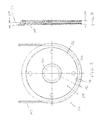
FIG. 2 is a side view of a sheave of the block shown inFIG. 1 , according to some embodiments. -
FIG. 3 is an edge view of the sheave ofFIG. 3 , according to some embodiments. -
FIG. 4 is close-up view of a groove of the sheave ofFIGS. 2 and 3 , according to some embodiments. - The present disclosure, in some embodiments, relates to material handling systems employing crown blocks and/or travelling blocks that include fleet angle tolerant sheaves. The crown and travelling blocks may be part of a block and tackle arrangement where the crown and travelling blocks are connected to one another with one or more returning sections of wire rope. That is, wire rope may extend from a winch or draw works to the crown block, down to the travelling block, and back up to the crown block. As the wire rope passes through each block, it may be reeved around a separate sheave for each pass through the block. The sheaves in the blocks may have a uniquely shaped sheave groove. The sheave groove may be shaped to accommodate relatively high and/or frequent fleet angles that may otherwise cause the wire rope to hang up on the rim of the sheave and intermittently drop into the groove. Without this disclosed groove, this hanging up and slipping may often be heard by crews as the travelling block travels and the wire rope slips. That is, as the rope slips and the sheave drops slightly and reengages the rope with the bottom of the groove, the impact can and resulting tightening of the rope can be heard. This undesired rubbing and/or wear on the rim and sidewalls of the groove which can lead to premature failure or replacement of the sheaves and/or the wire rope.
- In the oil industry, there are regulations and restrictions on the shape and profile of sheaves such as specified in American Petroleum Institute (API) 8A and 8C. The presently disclosed profile, in some embodiments, creates a sheave that can accommodate higher fleet angles while remaining in compliance with API 8A and 8C.
- As shown in
FIG. 1 , asimplified system 100 of a block and tackle arrangement in conjunction with a draw works 102 is shown. As shown, a portion of wire rope orother lifting line 104 may extend from the draw works 102 to thecrown block 106. Thecrown block 106 may be supported by a derrick 108 or other supporting structure. Thelifting line 104 may pass through thecrown block 106 and extend down to thetravelling block 110. In a single line set up, thelifting line 104 may be dead-ended at thetravelling block 110. In other embodiments, as shown, thelifting line 104 may be reeved through thetravelling block 110 across asheave 112 and may return to thecrown block 106. Each time the lifting line passes through thetravelling block 110 or thecrown block 106, thelifting line 104 may pass across asheave 112 for guiding theline 104 through the block and allowing theline 104 to translate through the block as thetravelling block 110 is lifted and/or lowered by hauling in or paying out, respectively, thelifting line 104. Depending on the number of returns from thetravelling block 110, differing reeving patterns may be used. In the present embodiment, 12 lines are used including 6 lines extending downward from the crown block to the travelling block and 6 lines returning to the crown block. In other embodiments, 14 or 16 lines may be used or another number of lines may be used depending on the desired capacity of the system. In some embodiments, the crown block may be skewed slightly or the sheaves in the crown block may be skewed to accommodate the lateral translation of each line as it returns from the travelling block to the crown block and engages a sheave adjacent to the sheave that it previously passed across. - As shown in
FIG. 1 , in some circumstances, thetravelling block 110 may be pulled out from below thecrown block 106. For example, in some cases, thetravelling block 110 may be lifted or lowered adjacent to tubulars in line with the well center to put the travelling block in position for the next anticipated operation. As thetravelling block 110 is pulled out from below thecrown block 106, as shown, thelifting lines 104 may become angled (i.e., fleet angle) as they exit thetravelling block 110 causing thelifting line 104 to engage the outer lips of the grooves on thesheaves 112 in theblock 110, causing theline 104 to ride along the lips of the grooves and intermittently drop into the groove. In some cases, both thetravelling block 110 and thecrown block 106 may experience wear due to the increased fleet angle, while in other embodiments, one or the other may experience the wear. - Referring now to
FIG. 2 , asheave 112 of one of the crown and/or travellingblock FIG. 1 is shown. Thesheave 112 may include a body portion orweb 114, an axle engaging portion or hub 116, and a rope engaging portion orrim 118. As mentioned, thesheave 112 may be configured to guide arope 104 passing through a crown or travellingblock sheave 112 may be particularly adapted to maintain therope 104 in a substantially constant tension condition as it passes through the block and may also be adapted to reduce or minimize kinking or abrupt bends in therope 104, which can lead to high stress concentrations and may create areas of fatigue or wear on therope 104. - The body portion or
web 114 of thesheave 112 may include a substantially robust structure configured for transferring tensile loads from thewire rope 104 to and through the axle engaging portion 116 of thesheave 112 to an axle or supporting structure of thesheave 112. Where therope engaging portion 118 of thesheave 112 is substantially circular, the tensile load in thewire rope 104 may impart a substantially uniform and radially acting pressure along therope engaging portion 118 of thesheave 112. Depending on the rigidity of therope engaging portion 118 relative to the rigidity of thebody portion 114, thebody portion 114 may transfer the substantially uniform and radially acting pressure substantially directly inward to the axle. In other embodiments, where thebody portion 114 is more akin to a spoke arrangement (either because it is relatively thin or because of an actual spoke-like structure), the rigidity of therope engaging portion 118 may function more akin to a compressed hoop. In this embodiment, the deflection of the hoop under the load of theline 104 may create tension in thebody portion 114 on the side of thebody portion 114 opposite the load, thereby causing thebody portion 114 to transfer the load to the axle engaging portion 116. - In some embodiments, the
body portion 114 may be a substantially planar structure that is substantially circular such that therope engaging portion 118 may be arranged substantially adjacent to thebody portion 114 and immediately radially outward from thebody portion 114. Thebody portion 114 may be substantially plate-like having a substantially constant thickness. In other embodiments, the thickness of thebody portion 114 may be thicker near the center of thesheave 112 and around the axle engaging portion 116, for example. Thebody portion 114 may have one or more ribs arranged on its surface extending substantially radially outward from the center of thebody portion 114 to the outer periphery of thebody portion 114. - The axle engaging portion or hub 116 of the
sheave 112 may be arranged immediately adjacent to thebody portion 114 on an inner radial edge thereof. The axle engaging portion 116 of thesheave 112 may include a thickened collar extending through the thickness of thesheave 112 and defining a substantially cylindrical bore 120 in which a bearing or other friction reducing element may be placed and secured. The bore 120 may be sized to house such a bearing and allow an axle or other shaft, rod, pin, or support structure to pass through the bearing. - The rope engaging portion or rim 118 of the
sheave 112 may be arranged along an outer periphery of thebody portion 114 opposite the axle engaging portion 116. Therope engaging portion 118 may be adapted to cause the lifting line orrope 104 to conform to a selected shape (i.e., a radial arc shape) as it passes around the perimeter of thesheave 112. As such, and as shown inFIG. 2 , therope engaging portion 118 may include a generally circular shape when viewing thesheave 112 from the side. The diameter of thesheave 112 and, thus, the diameter of therope engaging portion 118 may depend on several factors including the rope diameter, the design load, the block size, and several other factors. In some embodiments, the diameter of the rope engaging portion 118 (measured at outside or maximum diameter) may range from approximately 20 inches to approximately 114 inches or from approximately 40 inches to approximately 100 inches or from approximately 60 inches to approximately 80 inches. - The
rope engaging portion 118 may also be configured to cause therope 104 to remain in alignment with acenter plane 122 of thesheave 112 as it passes around thesheave 112. This may be particularly useful as thefleet angle 124 increases where sidewalls of therope engaging portion 118 hold the rope generally centered on thesheave 112 as it passes around thesheave 112. As shown inFIG. 3 , when viewed in cross-section, therope engaging portion 118 may include a generally saddle or groove shape, for example. Therope engaging portion 118 may be defined by abase portion 126 extending around the periphery of thebody portion 114. Thebase portion 126 may be thickened region around the periphery of thebody portion 114 of thesheave 112 or thebase portion 126 may have a thickness similar or the same as thebody portion 114. In the latter case, thebase portion 126 of therope engaging portion 118 may be an outer annular portion of thebody portion 114, for example. In the embodiment shown inFIG. 2 , thebase portion 126 is consistent with the former case where thebase portion 126 includes a thickened region along the periphery of thebody portion 114. The thickened region may have aradial height 128 sufficient to accommodate a groove which may be sized and shaped to accommodate a selected rope diameter or range of diameters. For example, in some embodiments, theradial height 128 of thebase portion 126 may range from approximately 2 3/8 inches to approximately 5 inches. The thickened region may have awidth 130 when viewed in cross-section for accommodating the rope diameter and providing sidewalls along the sides of the rope. For example, in some embodiments, thewidth 130 may range from approximately 2 3/8 inches to approximately 4 ½ inches. - Turning now to
FIG. 4 , a close-up view of a cross-section of the rope engaging portion is shown. As shown, thebase portion 126 may include agroove 132 that is particularly configured to receive a circular diameter rope and may provide a seat for the rope as it lays on the outer peripheral surface of thesheave 112. In particular, thegroove 132 may be defined by abottom surface 134 and a pair of opposingsidewalls 136 each extending upwardly from thebottom surface 134 torespective lips 138. - The
bottom surface 134 of thegroove 132 may be adapted to nestably engage the lifting line orwire rope 104 as it presses against thesheave 112. Thebottom surface 134 may thus be a concave surface extending between a pair of upper ends 140. The concave surface may have a curvature particularly adapted and modeled after the shape of the cross-section of thewire rope 104. In particular, thebottom surface 134 may have a curvature matching the curvature of the outer surface of thewire rope 104 or the curvature of thebottom surface 134 may be based on a radius slightly larger than the radius of thewire rope 104. For example, where the bottom surface curvature is too tight, therope 104 may not fully engage thebottom surface 134 and may, instead, be hung up on thesidewalls 136 of thegroove 132 causing excessive wear on thesidewalls 136 and pinching of therope 104, which may cause therope 104 to deteriorate. Where the bottom surface curvature is too broad, therope 104 may have a tendency to flatten as it passes across thesheave 112, which may also cause therope 104 to deteriorate more quickly. As such, the bottom surface curvature may be similar to the curvature of the outer surface of thewire rope 104. In some embodiments, the curvature may be defined by a radius that is based on the rope diameter multiplied by a factor ranging from approximately 1.01 to 1.2. In some embodiments, where the sheave groove is designed to meet API specifications, the factor may range from 1.06 to 1.1. - The
bottom surface 134 may define an includedangle 142 defining how much of thebottom surface 134 comes into contact with the surface of the wire rope. In some embodiments, thebottom surface 134 may have an includedangle 142 ranging from approximately 0 degrees to approximately 60 degrees or from approximately 20 degrees to approximately 40 degrees or the includedangle 142 may be approximately 30 degrees. In some embodiments, wheresheaves 112 are designed to meet specification of the American Petroleum Institute (API) (e.g., API 8A and 8C), the includedangle 142 may be approximately 30 degrees or theangle 144 subtended by the upper ends 140 may be approximately 150 degrees. Still other includedangles 142 may be provided depending on the shape, size, and type of rope or lifting line being provided. In any of the above cases, the angle 146, relative to the horizontal of theupper end 140 of thebottom surface 134 may be approximately ½ of 180 degrees less the includedangle 142. That is, where the included angle is 30 degrees, for example, the upper ends 140 of thebottom surface 134 may extend upwardly at an angle of approximately 75 degrees from the horizontal. In addition, as shown, the bottom surface of the groove may be symmetrical about the centerline of the sheave and, as such, the includedangle 142 may be made up of twohalf angles 143 as shown. - The
sidewalls 136 of thegroove 132 may be adjacent and/or immediately adjacent to the upper ends 140 of thebottom surface 134 and may extend upwardly from the upper ends 140 of thebottom surface 134. As shown, thesidewalls 136 may initially be tangential to or in alignment with the upper ends 140 of thebottom surface 134 such that, initially, thesidewalls 136 extend upwardly from the horizontal at the same angle as the upper ends 140 of thebottom surface 134. In other embodiments, thesidewalls 136 might not be tangential and may, instead, extend at a shallower or more upright angle relative to the upper ends 140 of thebottom surface 134. Where sheaves are designed to meet API specifications, thesidewalls 136 may initially extend from the upper ends 140 of the bottom surface tangentially as shown. - As shown in
FIG. 4 , thesidewalls 136 may be curved or contoured sidewalls. That is, in contrast to groove profiles where the sidewalls are flat and extend tangentially upwardly from thebottom surface 134, thesidewalls 136 ofFIG. 4 are not flat and, instead have a curved surface. As shown, while thesidewalls 136 may initially be tangential to the upper ends 140 of thebottom surface 134, thesidewalls 136 may have a curvature that may be defined by aradius 147. The curvature may be a generally convex curvature relative to thegroove space 132 and, as such, may cause thesidewalls 136 to increasingly diverge away from thegroove space 132 as thesidewalls 136 extend upwardly. That is, while flat sidewalls may be said to diverge as they extend upwardly, the present sidewalls increasingly diverge due to the curvature. The radius line of thecurved sidewall 136 may extend substantially perpendicularly to the tangent point at the upper ends 140 of thebottom surface 134 and may have acenter point 148 defined by the length of theradius 147. That is, for an includedangle 142 of approximately 30 degrees and a sidewall curvature radius of R inches, thecenter point 148 of theradiused sidewall 136 may be R inches down and to the right of the upper end of the right upper sidewall at an angle of approximately 15 degrees. While a radiused curve has been described, in other embodiments, the curvature may be other parabolic curves, elliptical curves, or spiral shapes, for example. The amount of curvature of thesidewalls 136 may depend on a variety of factors including the rope diameter, the sheave diameter, and the desired fleet angle to be accommodated. - In some embodiments, depending on the rope diameter, the sheave diameter, and the desired fleet angle, the radius of the sidewalls may range from approximately 3 inches to approximately 30 inches or from approximately 4 inches to approximately 25 inches or from approximately 5 inches to approximately 21 inches. Any particular value within ranges mentioned may have particular advantages and may be selected. Still other radii outside or within the ranges described may be provided. In one example model, for a design fleet angle of 7 degrees, the following wall radii were determined:
Wall Radius "R wall" (inches) Rope Dia. Sheave Diameter 72 78 1.750 13.00 11.75 1.875 14.50 13.00 2.000 17.50 15.50 2.125 21.00 18.75 2.250 23.25 20.50 - In addition, for a sheave diameter of 60 inches, for example, a wall radius ranging from 5 5/8 inches to approximately 16 ¾ inches may be used. For example, with a sheave diameter of 60 inches and a rope diameter of 1 1/8 inches, a wall radius of 5 5/8 inches may provide for a fleet angle of 7 degrees.
- It is to be appreciated that the wall radius may increase the width of the groove at the outer peripheral edge of the sheave. This increased groove width may accommodate the fleet angle by limiting the engagement of the rope with the lip of the sheave groove, which may reduce or prevent the rope from hanging up on the sheave groove and intermittently slipping into the groove. As such a smoother operation may be performed and sheave and rope life may be increased.
- The
sidewalls 136 may extend upwardly along the groove space to a top edge 150. Thesidewalls 136, for example, may extend substantially the full remaining height of thegroove 132 above thebottom surface 134. For example, where the full height of thegroove 132 is measured from the outer peripheral surface of the sheave to the bottom of thebottom surface 134, the sidewalls may extend approximately 50% to 80%, or approximately 60% to 75%, or approximately 67% of the height of thegroove 132. The remaining height of the groove may be provided by thebottom surface 134 and theupper lips 138. - The
upper lips 138 on each side of thegroove 132 may be tangential to an upper end 150 of the sidewall. In other embodiments, theupper lips 138 may extend at angle different than the upper end angle of thesidewalls 136. Theupper lips 138 may include a curved surface having a curvature greater than that of thesidewall 136 and may have a flat top surface defining the outermost peripheral surface of thesheave 112. In some embodiments, this outermost peripheral surface may not be flat but, instead, may be curved as thelip 138 may curve away from thesidewall 136 and continue to an outside surface of thebase portion 126 of therope engaging portion 118 of thesheave 112. The curved surface portion of thelip 138 may have a radius ranging from approximately 1/8 inch to approximately ½ inch or from approximately 3/16 inch to approximately 3/8 inch or the curved surface portion of the lip may have a radius of approximately ¼". Still other radii outside or within the ranges mentioned may be provided. - In the foregoing description various embodiments of the present disclosure have been presented for the purpose of illustration and description. They are not intended to be exhaustive or to limit the invention to the precise form disclosed. Obvious modifications or variations are possible in light of the above teachings. The various embodiments were chosen and described to provide the best illustration of the principals of the disclosure and their practical application, and to enable one of ordinary skill in the art to utilize the various embodiments with various modifications as are suited to the particular use contemplated. All such modifications and variations are within the scope of the present disclosure as determined by the appended claims when interpreted in accordance with the breadth they are fairly, legally, and equitably entitled.
Claims (15)
- A sheave, comprising:a body portion with a circular circumference and defining a center plane;a bore extending through the body portion and configured for receiving a shaft and allowing the body portion to rotate in the center plane; anda rope groove arranged on the circular circumference, comprising:a radiused bottom with a first end and a second end; anda pair of opposing sidewalls each extending directly and tangentially from one of the first and second end and having a curved profile.
- The block of claim 1, wherein the curved profile diverges from the center plane.
- The block of claim 2, wherein the curved profile is a radiused profile.
- The block of claim 3, wherein the radiused profile is defined by a radius ranging from approximately 3 inches to approximately 30 inches.
- The block of claim 4, wherein the radiused profile is defined by a radius ranging from approximately 4 inches to approximately 25 inches.
- The block of claim 5, wherein the radiused profile is defined by a radius ranging from approximately 5 inches to approximately 21 inches.
- The block of claim 2, wherein the curved profile is a parabolic profile.
- The block of claim 2, wherein the curved profile is an elliptical profile.
- A block for use in a block and tackle arrangement, the block comprising:a body portion; anda sheave arranged in the body portion for substantially free rotation, the sheave defining a center plane and having a groove arranged along a circumference thereof, the groove comprising:a radiused bottom with a first end and a second end; anda pair of opposing sidewalls each extending directly and tangentially from one of the first and second end and having a curved profile.
- The block of claim 9, wherein the curved profile diverges from the center plane.
- The block of claim 10, wherein the curved profile is a radiused profile.
- The block of claim 11, wherein the radiused profile is defined by a radius ranging from approximately 3 inches to approximately 30 inches.
- The block of claim 12, wherein the radiused profile is defined by a radius ranging from approximately 4 inches to approximately 25 inches.
- The block of claim 13, wherein the radiused profile is defined by a radius ranging from approximately 5 inches to approximately 21 inches.
- The block of claim 10, wherein the curved profile is(i) a parabolic profile, or(ii) an elliptical profile.
Applications Claiming Priority (1)
| Application Number | Priority Date | Filing Date | Title |
|---|---|---|---|
| US14/251,938 US10557540B2 (en) | 2014-04-14 | 2014-04-14 | Fleet angle tolerant sheave |
Publications (2)
| Publication Number | Publication Date |
|---|---|
| EP2933220A1 true EP2933220A1 (en) | 2015-10-21 |
| EP2933220B1 EP2933220B1 (en) | 2024-03-06 |
Family
ID=52573620
Family Applications (1)
| Application Number | Title | Priority Date | Filing Date |
|---|---|---|---|
| EP15156151.1A Active EP2933220B1 (en) | 2014-04-14 | 2015-02-23 | Fleet angle tolerant sheave |
Country Status (4)
| Country | Link |
|---|---|
| US (1) | US10557540B2 (en) |
| EP (1) | EP2933220B1 (en) |
| CN (1) | CN104976322B (en) |
| CA (1) | CA2874138C (en) |
Cited By (3)
| Publication number | Priority date | Publication date | Assignee | Title |
|---|---|---|---|---|
| EP3252000A1 (en) | 2016-06-02 | 2017-12-06 | National Oilwell Varco Norway AS | In-line spooling device for compensating fleet angle |
| US10557540B2 (en) | 2014-04-14 | 2020-02-11 | National Oilwell Varco, L.P. | Fleet angle tolerant sheave |
| US11279601B2 (en) | 2017-04-03 | 2022-03-22 | National Oilwell Varco, L.P. | Hoisting and tensioning bearing saver |
Families Citing this family (13)
| Publication number | Priority date | Publication date | Assignee | Title |
|---|---|---|---|---|
| DE202011001845U1 (en) | 2011-01-24 | 2012-04-30 | Liebherr-Components Biberach Gmbh | Cable drum and pulley for fiber rope drives |
| US20170170642A1 (en) * | 2015-12-09 | 2017-06-15 | Sherman + Reilly, Inc. | Sheave profile |
| WO2018044829A1 (en) * | 2016-08-30 | 2018-03-08 | Maclean Power, L.L.C. | Double v stringing block |
| JP6857476B2 (en) * | 2016-09-30 | 2021-04-14 | 株式会社シマノ | Both bearing reel spools and both bearing reels |
| US11473989B2 (en) * | 2018-07-31 | 2022-10-18 | Illinois Tool Works Inc. | Multi-dimensional sheave for use in tension measurement systems |
| CN110792399A (en) * | 2018-08-03 | 2020-02-14 | 国民油井华高有限公司 | Hoisting system, robotic manipulator and method for handling tubulars on a drilling rig and tubular handling system and method |
| US11613940B2 (en) | 2018-08-03 | 2023-03-28 | National Oilwell Varco, L.P. | Devices, systems, and methods for robotic pipe handling |
| CN109573873B (en) * | 2018-11-28 | 2020-11-24 | 上海宇航系统工程研究所 | Multi-point compressed tether clamping and conveying mechanism |
| WO2020151386A1 (en) | 2019-01-25 | 2020-07-30 | National Oilwell Varco, L.P. | Pipe handling arm |
| US11988059B2 (en) | 2019-02-22 | 2024-05-21 | National Oilwell Varco, L.P. | Dual activity top drive |
| US11834914B2 (en) | 2020-02-10 | 2023-12-05 | National Oilwell Varco, L.P. | Quick coupling drill pipe connector |
| CN112161034A (en) * | 2020-04-30 | 2021-01-01 | 内蒙古工业大学 | Anti-groove-jumping cambered surface pulley |
| CN111623032A (en) * | 2020-06-16 | 2020-09-04 | 内蒙古工业大学 | A pulley structure and method for realizing the pulley structure |
Citations (4)
| Publication number | Priority date | Publication date | Assignee | Title |
|---|---|---|---|---|
| US639762A (en) * | 1899-03-15 | 1899-12-26 | Arthur Painter | Grip-pulley. |
| US2730795A (en) * | 1951-02-06 | 1956-01-17 | Dresser Equipment Company | Wire line sheave and method of fabrication |
| US3512757A (en) * | 1968-02-23 | 1970-05-19 | Cons Electric Corp | Magnetic traction line haul |
| US4492363A (en) * | 1979-12-20 | 1985-01-08 | Niskin Shale J | Multiple pulley sheave assembly with retainer pulleys |
Family Cites Families (50)
| Publication number | Priority date | Publication date | Assignee | Title |
|---|---|---|---|---|
| US432701A (en) * | 1890-07-22 | grimm | ||
| US829898A (en) * | 1906-03-06 | 1906-08-28 | William J Dornbach | Rope-sheave. |
| US1369319A (en) | 1919-05-01 | 1921-02-22 | Bollen Guillaume | Pulley |
| US1362778A (en) | 1920-07-12 | 1920-12-21 | John B Castino | Pulley construction |
| GB261207A (en) | 1925-12-18 | 1926-11-18 | Charles William Taylor | Improvements in and relating to pulleys |
| GB285653A (en) | 1927-02-28 | 1928-02-23 | Edwin Appleby | Improvements relating to pulleys |
| US2806380A (en) * | 1955-10-24 | 1957-09-17 | L E Myers Co | Sheave block for stringing aluminum cable |
| US3292908A (en) * | 1965-02-04 | 1966-12-20 | Washington Iron Works | Head mounting for main and haulback sheaves of a logging spar |
| US3385563A (en) * | 1966-10-17 | 1968-05-28 | Thomas W. Stinson Jr. | Block for supporting and guiding a line or the like |
| DE1900707B2 (en) | 1969-01-08 | 1973-07-05 | PROCESS AND BULK FOR MANUFACTURING ROPE ROLLS | |
| US3868089A (en) * | 1972-08-21 | 1975-02-25 | Keith E Lindsey | Helicopter threadable stringing block assembly for power conductors |
| US3934482A (en) * | 1975-01-27 | 1976-01-27 | The United States Of America As Represented By The Secretary Of The Navy | Cable traction sheave |
| US4018422A (en) * | 1975-09-09 | 1977-04-19 | Lindsey Manufacturing Company | Bundle conductor stringing block with rotary threading gate |
| US4177685A (en) | 1978-02-13 | 1979-12-11 | Delancey Warren H | Pulley |
| AT361537B (en) | 1978-06-16 | 1981-03-10 | Semperit Ag | ROPE ROLLING |
| US4301995A (en) * | 1979-12-20 | 1981-11-24 | Niskin Shale J | Counter-balanced sheave |
| US4413981A (en) | 1981-06-12 | 1983-11-08 | White Eugene F | Sheave |
| US4480818A (en) * | 1982-09-02 | 1984-11-06 | Schlumberger Technology Corporation | Safety enhancement device for well-logging cable sheave wheels |
| DE3426802C1 (en) | 1984-07-20 | 1986-02-06 | Dnepropetrovskij metallurgičeskij institut imeni L. I. Brežneva, Dnepropetrovsk | Method of manufacturing a pulley |
| SU1696368A1 (en) | 1985-07-01 | 1991-12-07 | Ивано-Франковский Институт Нефти И Газа | Lining of pulley |
| US5490814A (en) | 1995-04-26 | 1996-02-13 | Deere & Company | Power transmission sheave |
| US5984586A (en) * | 1997-02-04 | 1999-11-16 | Continental Emsco Company | Mooring unit and retrofitting method |
| US6041476A (en) * | 1997-11-21 | 2000-03-28 | Caldwell Manufacturing Company | Inverted block and tackle window balance |
| US6105939A (en) * | 1998-04-03 | 2000-08-22 | Wireline Technologies, Inc. | Stuffing box sheave assembly with retention pad |
| DE19816327C2 (en) | 1998-04-11 | 2002-06-13 | Wilhelm Kaechele Gmbh Elastome | pulley |
| CA2287676A1 (en) | 1998-12-07 | 2000-06-07 | Harnischfeger Technologies, Inc. | An improved groove design for wire rope drums and sheaves |
| JP2000229789A (en) | 1999-02-12 | 2000-08-22 | Nippon Yusoki Co Ltd | Wire rope winding device |
| JP3688555B2 (en) | 2000-05-30 | 2005-08-31 | 株式会社エンプラス | Resin gear, image forming apparatus, and resin rotation transmission means |
| US20040026676A1 (en) | 2002-08-06 | 2004-02-12 | Smith Rory Stephen | Modular sheave assemblies |
| FR2843953B1 (en) * | 2002-08-28 | 2005-04-08 | Kley France | WINCH TYPE A CABESTAN |
| JP2005053597A (en) | 2003-08-04 | 2005-03-03 | Toyota Industries Corp | Hydraulic pipe structure of industrial vehicle |
| US20060000058A1 (en) * | 2004-06-21 | 2006-01-05 | Caldwell Manufacturing Company | Block and tackle window balance with integrally molded middle carriage assembly and cord |
| US20060231812A1 (en) * | 2005-04-01 | 2006-10-19 | Ziech James F | Cable driven drive mechanism |
| EP2054335B1 (en) * | 2006-08-15 | 2012-04-04 | Hydralift Amclyde, Inc. | Direct acting single sheave active/passiv heave compensator |
| US7770324B2 (en) * | 2006-11-22 | 2010-08-10 | James Hogan | Multi-faceted irrigating pole planters that can be easily raised and locked for use and lowered for service |
| US20080161141A1 (en) | 2006-12-27 | 2008-07-03 | Jang-Hyuk Joo | Water pump pulley for cooling system of vehicle |
| WO2008110241A2 (en) * | 2007-03-12 | 2008-09-18 | Inventio Ag | Elevator system, carrying means for an elevator system, and method for the production of a carrying means |
| US20090291793A1 (en) | 2008-05-23 | 2009-11-26 | Gerard Marchesseault | Pulley Apparatus for Retaining an Object in a Stationary Position |
| US8616189B2 (en) | 2008-09-30 | 2013-12-31 | Mcp Ip, Llc | Flexible cable guard |
| US20110118067A1 (en) | 2009-11-13 | 2011-05-19 | Henry Bronson | Drive with Belt |
| NL2004908C2 (en) * | 2010-06-17 | 2011-12-20 | Itrec Bv | Double drum traction winch. |
| DE102010060260A1 (en) | 2010-10-29 | 2012-05-03 | Ensinger Gmbh | pulley |
| DE202011001845U1 (en) * | 2011-01-24 | 2012-04-30 | Liebherr-Components Biberach Gmbh | Cable drum and pulley for fiber rope drives |
| US8398057B2 (en) * | 2011-07-12 | 2013-03-19 | Arie Leib Tukachinsky | Stringing block for aerial electric conductor |
| US8485951B1 (en) * | 2011-08-02 | 2013-07-16 | Frederick R. Adams | Vehicle mounted multi-position resistance tube exercise apparatus |
| SI2756125T1 (en) | 2011-09-13 | 2016-07-29 | Meccanica Generale - S.R.L. | A plastic pulley for driving drum of a washing machine into rotation |
| CN202251826U (en) | 2011-09-14 | 2012-05-30 | 河南柯尼达自动化科技有限公司 | Self-locking shaft end clamping plate |
| WO2013063400A1 (en) * | 2011-10-27 | 2013-05-02 | Electronic Theatre Controls, Inc. | Loft block with aligned sheaves |
| US9702208B2 (en) * | 2013-02-27 | 2017-07-11 | Jesse Urquhart | Replaceably lined cable guides and tensioning roller for drill line slip and cut operations on a drilling rig |
| US10557540B2 (en) | 2014-04-14 | 2020-02-11 | National Oilwell Varco, L.P. | Fleet angle tolerant sheave |
-
2014
- 2014-04-14 US US14/251,938 patent/US10557540B2/en active Active
- 2014-12-10 CA CA2874138A patent/CA2874138C/en active Active
-
2015
- 2015-02-23 EP EP15156151.1A patent/EP2933220B1/en active Active
- 2015-04-13 CN CN201510173708.1A patent/CN104976322B/en active Active
Patent Citations (4)
| Publication number | Priority date | Publication date | Assignee | Title |
|---|---|---|---|---|
| US639762A (en) * | 1899-03-15 | 1899-12-26 | Arthur Painter | Grip-pulley. |
| US2730795A (en) * | 1951-02-06 | 1956-01-17 | Dresser Equipment Company | Wire line sheave and method of fabrication |
| US3512757A (en) * | 1968-02-23 | 1970-05-19 | Cons Electric Corp | Magnetic traction line haul |
| US4492363A (en) * | 1979-12-20 | 1985-01-08 | Niskin Shale J | Multiple pulley sheave assembly with retainer pulleys |
Cited By (3)
| Publication number | Priority date | Publication date | Assignee | Title |
|---|---|---|---|---|
| US10557540B2 (en) | 2014-04-14 | 2020-02-11 | National Oilwell Varco, L.P. | Fleet angle tolerant sheave |
| EP3252000A1 (en) | 2016-06-02 | 2017-12-06 | National Oilwell Varco Norway AS | In-line spooling device for compensating fleet angle |
| US11279601B2 (en) | 2017-04-03 | 2022-03-22 | National Oilwell Varco, L.P. | Hoisting and tensioning bearing saver |
Also Published As
| Publication number | Publication date |
|---|---|
| CN104976322B (en) | 2020-11-03 |
| CA2874138A1 (en) | 2015-10-14 |
| US20150291403A1 (en) | 2015-10-15 |
| EP2933220B1 (en) | 2024-03-06 |
| CA2874138C (en) | 2021-12-07 |
| US10557540B2 (en) | 2020-02-11 |
| CN104976322A (en) | 2015-10-14 |
Similar Documents
| Publication | Publication Date | Title |
|---|---|---|
| US10557540B2 (en) | Fleet angle tolerant sheave | |
| US8286947B2 (en) | Pulley apparatus | |
| RU2722130C1 (en) | Hoisting device of rope hoisting gear | |
| US11279601B2 (en) | Hoisting and tensioning bearing saver | |
| CN215558287U (en) | Telescopic sleeve structure and telescopic sleeve thereof | |
| CN113772559B (en) | Cable crane cable saddle self-adaptive adjusting system | |
| US10047848B2 (en) | Sheave with structured web | |
| CN202046793U (en) | Special strut for ultra-long flexible steel plate | |
| CN203021166U (en) | Steel plate lifting appliance | |
| CN205132984U (en) | Portable little loop wheel machine | |
| CN209455931U (en) | One kind using suspender for Long-distance Transmission Pipeline construction | |
| CN209041886U (en) | Suspension device for bridge pier crack detection | |
| US11554938B2 (en) | Hoisting arrangement of a hoist of a crane | |
| CN107614418B (en) | Rope roll system | |
| CN204057807U (en) | A kind of winch three rolling wheel regulator | |
| CN211871145U (en) | Light-duty shaped steel hoist device | |
| CN104743463B (en) | A wire rope protection device and a rotary drilling rig having the same | |
| CN207312945U (en) | Assembled lifting lug assembly and hoisting and fixing structure of jib | |
| CN206955443U (en) | A kind of crane hanger | |
| RU166404U1 (en) | LIFTING DRUM | |
| CN104627884B (en) | Steel wire rope deflection winding mechanism | |
| CN206940199U (en) | A kind of flat type steel wire rope lifts by crane guider | |
| CN104724573B (en) | Lift facility | |
| CN108341359B (en) | A kind of servo-actuated Winch Wire Rope Ranging Device | |
| CN205715564U (en) | A kind of lifting rope sheave |
Legal Events
| Date | Code | Title | Description |
|---|---|---|---|
| PUAI | Public reference made under article 153(3) epc to a published international application that has entered the european phase |
Free format text: ORIGINAL CODE: 0009012 |
|
| AK | Designated contracting states |
Kind code of ref document: A1 Designated state(s): AL AT BE BG CH CY CZ DE DK EE ES FI FR GB GR HR HU IE IS IT LI LT LU LV MC MK MT NL NO PL PT RO RS SE SI SK SM TR |
|
| AX | Request for extension of the european patent |
Extension state: BA ME |
|
| 17P | Request for examination filed |
Effective date: 20160421 |
|
| RBV | Designated contracting states (corrected) |
Designated state(s): AL AT BE BG CH CY CZ DE DK EE ES FI FR GB GR HR HU IE IS IT LI LT LU LV MC MK MT NL NO PL PT RO RS SE SI SK SM TR |
|
| 17Q | First examination report despatched |
Effective date: 20160822 |
|
| STAA | Information on the status of an ep patent application or granted ep patent |
Free format text: STATUS: EXAMINATION IS IN PROGRESS |
|
| GRAP | Despatch of communication of intention to grant a patent |
Free format text: ORIGINAL CODE: EPIDOSNIGR1 |
|
| STAA | Information on the status of an ep patent application or granted ep patent |
Free format text: STATUS: GRANT OF PATENT IS INTENDED |
|
| INTG | Intention to grant announced |
Effective date: 20230301 |
|
| GRAJ | Information related to disapproval of communication of intention to grant by the applicant or resumption of examination proceedings by the epo deleted |
Free format text: ORIGINAL CODE: EPIDOSDIGR1 |
|
| STAA | Information on the status of an ep patent application or granted ep patent |
Free format text: STATUS: EXAMINATION IS IN PROGRESS |
|
| INTC | Intention to grant announced (deleted) | ||
| GRAP | Despatch of communication of intention to grant a patent |
Free format text: ORIGINAL CODE: EPIDOSNIGR1 |
|
| STAA | Information on the status of an ep patent application or granted ep patent |
Free format text: STATUS: GRANT OF PATENT IS INTENDED |
|
| P01 | Opt-out of the competence of the unified patent court (upc) registered |
Effective date: 20230530 |
|
| INTG | Intention to grant announced |
Effective date: 20230628 |
|
| GRAJ | Information related to disapproval of communication of intention to grant by the applicant or resumption of examination proceedings by the epo deleted |
Free format text: ORIGINAL CODE: EPIDOSDIGR1 |
|
| STAA | Information on the status of an ep patent application or granted ep patent |
Free format text: STATUS: EXAMINATION IS IN PROGRESS |
|
| GRAP | Despatch of communication of intention to grant a patent |
Free format text: ORIGINAL CODE: EPIDOSNIGR1 |
|
| STAA | Information on the status of an ep patent application or granted ep patent |
Free format text: STATUS: GRANT OF PATENT IS INTENDED |
|
| INTC | Intention to grant announced (deleted) | ||
| INTG | Intention to grant announced |
Effective date: 20231011 |
|
| GRAS | Grant fee paid |
Free format text: ORIGINAL CODE: EPIDOSNIGR3 |
|
| GRAA | (expected) grant |
Free format text: ORIGINAL CODE: 0009210 |
|
| STAA | Information on the status of an ep patent application or granted ep patent |
Free format text: STATUS: THE PATENT HAS BEEN GRANTED |
|
| AK | Designated contracting states |
Kind code of ref document: B1 Designated state(s): AL AT BE BG CH CY CZ DE DK EE ES FI FR GB GR HR HU IE IS IT LI LT LU LV MC MK MT NL NO PL PT RO RS SE SI SK SM TR |
|
| REG | Reference to a national code |
Ref country code: GB Ref legal event code: FG4D |
|
| REG | Reference to a national code |
Ref country code: CH Ref legal event code: EP |
|
| REG | Reference to a national code |
Ref country code: DE Ref legal event code: R096 Ref document number: 602015087784 Country of ref document: DE |
|
| REG | Reference to a national code |
Ref country code: IE Ref legal event code: FG4D |
|
| REG | Reference to a national code |
Ref country code: LT Ref legal event code: MG9D |
|
| PG25 | Lapsed in a contracting state [announced via postgrant information from national office to epo] |
Ref country code: LT Free format text: LAPSE BECAUSE OF FAILURE TO SUBMIT A TRANSLATION OF THE DESCRIPTION OR TO PAY THE FEE WITHIN THE PRESCRIBED TIME-LIMIT Effective date: 20240306 |
|
| REG | Reference to a national code |
Ref country code: NL Ref legal event code: MP Effective date: 20240306 |
|
| PG25 | Lapsed in a contracting state [announced via postgrant information from national office to epo] |
Ref country code: GR Free format text: LAPSE BECAUSE OF FAILURE TO SUBMIT A TRANSLATION OF THE DESCRIPTION OR TO PAY THE FEE WITHIN THE PRESCRIBED TIME-LIMIT Effective date: 20240607 |
|
| PG25 | Lapsed in a contracting state [announced via postgrant information from national office to epo] |
Ref country code: HR Free format text: LAPSE BECAUSE OF FAILURE TO SUBMIT A TRANSLATION OF THE DESCRIPTION OR TO PAY THE FEE WITHIN THE PRESCRIBED TIME-LIMIT Effective date: 20240306 Ref country code: RS Free format text: LAPSE BECAUSE OF FAILURE TO SUBMIT A TRANSLATION OF THE DESCRIPTION OR TO PAY THE FEE WITHIN THE PRESCRIBED TIME-LIMIT Effective date: 20240606 |
|
| PG25 | Lapsed in a contracting state [announced via postgrant information from national office to epo] |
Ref country code: ES Free format text: LAPSE BECAUSE OF FAILURE TO SUBMIT A TRANSLATION OF THE DESCRIPTION OR TO PAY THE FEE WITHIN THE PRESCRIBED TIME-LIMIT Effective date: 20240306 |
|
| PG25 | Lapsed in a contracting state [announced via postgrant information from national office to epo] |
Ref country code: RS Free format text: LAPSE BECAUSE OF FAILURE TO SUBMIT A TRANSLATION OF THE DESCRIPTION OR TO PAY THE FEE WITHIN THE PRESCRIBED TIME-LIMIT Effective date: 20240606 Ref country code: LT Free format text: LAPSE BECAUSE OF FAILURE TO SUBMIT A TRANSLATION OF THE DESCRIPTION OR TO PAY THE FEE WITHIN THE PRESCRIBED TIME-LIMIT Effective date: 20240306 Ref country code: HR Free format text: LAPSE BECAUSE OF FAILURE TO SUBMIT A TRANSLATION OF THE DESCRIPTION OR TO PAY THE FEE WITHIN THE PRESCRIBED TIME-LIMIT Effective date: 20240306 Ref country code: GR Free format text: LAPSE BECAUSE OF FAILURE TO SUBMIT A TRANSLATION OF THE DESCRIPTION OR TO PAY THE FEE WITHIN THE PRESCRIBED TIME-LIMIT Effective date: 20240607 Ref country code: FI Free format text: LAPSE BECAUSE OF FAILURE TO SUBMIT A TRANSLATION OF THE DESCRIPTION OR TO PAY THE FEE WITHIN THE PRESCRIBED TIME-LIMIT Effective date: 20240306 Ref country code: ES Free format text: LAPSE BECAUSE OF FAILURE TO SUBMIT A TRANSLATION OF THE DESCRIPTION OR TO PAY THE FEE WITHIN THE PRESCRIBED TIME-LIMIT Effective date: 20240306 Ref country code: BG Free format text: LAPSE BECAUSE OF FAILURE TO SUBMIT A TRANSLATION OF THE DESCRIPTION OR TO PAY THE FEE WITHIN THE PRESCRIBED TIME-LIMIT Effective date: 20240306 |
|
| REG | Reference to a national code |
Ref country code: AT Ref legal event code: MK05 Ref document number: 1663330 Country of ref document: AT Kind code of ref document: T Effective date: 20240306 |
|
| PG25 | Lapsed in a contracting state [announced via postgrant information from national office to epo] |
Ref country code: SE Free format text: LAPSE BECAUSE OF FAILURE TO SUBMIT A TRANSLATION OF THE DESCRIPTION OR TO PAY THE FEE WITHIN THE PRESCRIBED TIME-LIMIT Effective date: 20240306 Ref country code: LV Free format text: LAPSE BECAUSE OF FAILURE TO SUBMIT A TRANSLATION OF THE DESCRIPTION OR TO PAY THE FEE WITHIN THE PRESCRIBED TIME-LIMIT Effective date: 20240306 |
|
| PG25 | Lapsed in a contracting state [announced via postgrant information from national office to epo] |
Ref country code: NL Free format text: LAPSE BECAUSE OF FAILURE TO SUBMIT A TRANSLATION OF THE DESCRIPTION OR TO PAY THE FEE WITHIN THE PRESCRIBED TIME-LIMIT Effective date: 20240306 |
|
| PG25 | Lapsed in a contracting state [announced via postgrant information from national office to epo] |
Ref country code: NL Free format text: LAPSE BECAUSE OF FAILURE TO SUBMIT A TRANSLATION OF THE DESCRIPTION OR TO PAY THE FEE WITHIN THE PRESCRIBED TIME-LIMIT Effective date: 20240306 |
|
| PG25 | Lapsed in a contracting state [announced via postgrant information from national office to epo] |
Ref country code: IS Free format text: LAPSE BECAUSE OF FAILURE TO SUBMIT A TRANSLATION OF THE DESCRIPTION OR TO PAY THE FEE WITHIN THE PRESCRIBED TIME-LIMIT Effective date: 20240706 |
|
| PG25 | Lapsed in a contracting state [announced via postgrant information from national office to epo] |
Ref country code: PT Free format text: LAPSE BECAUSE OF FAILURE TO SUBMIT A TRANSLATION OF THE DESCRIPTION OR TO PAY THE FEE WITHIN THE PRESCRIBED TIME-LIMIT Effective date: 20240708 Ref country code: SM Free format text: LAPSE BECAUSE OF FAILURE TO SUBMIT A TRANSLATION OF THE DESCRIPTION OR TO PAY THE FEE WITHIN THE PRESCRIBED TIME-LIMIT Effective date: 20240306 |
|
| PG25 | Lapsed in a contracting state [announced via postgrant information from national office to epo] |
Ref country code: EE Free format text: LAPSE BECAUSE OF FAILURE TO SUBMIT A TRANSLATION OF THE DESCRIPTION OR TO PAY THE FEE WITHIN THE PRESCRIBED TIME-LIMIT Effective date: 20240306 Ref country code: CZ Free format text: LAPSE BECAUSE OF FAILURE TO SUBMIT A TRANSLATION OF THE DESCRIPTION OR TO PAY THE FEE WITHIN THE PRESCRIBED TIME-LIMIT Effective date: 20240306 |
|
| PG25 | Lapsed in a contracting state [announced via postgrant information from national office to epo] |
Ref country code: AT Free format text: LAPSE BECAUSE OF FAILURE TO SUBMIT A TRANSLATION OF THE DESCRIPTION OR TO PAY THE FEE WITHIN THE PRESCRIBED TIME-LIMIT Effective date: 20240306 |
|
| PG25 | Lapsed in a contracting state [announced via postgrant information from national office to epo] |
Ref country code: PL Free format text: LAPSE BECAUSE OF FAILURE TO SUBMIT A TRANSLATION OF THE DESCRIPTION OR TO PAY THE FEE WITHIN THE PRESCRIBED TIME-LIMIT Effective date: 20240306 |
|
| PG25 | Lapsed in a contracting state [announced via postgrant information from national office to epo] |
Ref country code: SK Free format text: LAPSE BECAUSE OF FAILURE TO SUBMIT A TRANSLATION OF THE DESCRIPTION OR TO PAY THE FEE WITHIN THE PRESCRIBED TIME-LIMIT Effective date: 20240306 |
|
| PG25 | Lapsed in a contracting state [announced via postgrant information from national office to epo] |
Ref country code: SM Free format text: LAPSE BECAUSE OF FAILURE TO SUBMIT A TRANSLATION OF THE DESCRIPTION OR TO PAY THE FEE WITHIN THE PRESCRIBED TIME-LIMIT Effective date: 20240306 Ref country code: SK Free format text: LAPSE BECAUSE OF FAILURE TO SUBMIT A TRANSLATION OF THE DESCRIPTION OR TO PAY THE FEE WITHIN THE PRESCRIBED TIME-LIMIT Effective date: 20240306 Ref country code: RO Free format text: LAPSE BECAUSE OF FAILURE TO SUBMIT A TRANSLATION OF THE DESCRIPTION OR TO PAY THE FEE WITHIN THE PRESCRIBED TIME-LIMIT Effective date: 20240306 Ref country code: PT Free format text: LAPSE BECAUSE OF FAILURE TO SUBMIT A TRANSLATION OF THE DESCRIPTION OR TO PAY THE FEE WITHIN THE PRESCRIBED TIME-LIMIT Effective date: 20240708 Ref country code: PL Free format text: LAPSE BECAUSE OF FAILURE TO SUBMIT A TRANSLATION OF THE DESCRIPTION OR TO PAY THE FEE WITHIN THE PRESCRIBED TIME-LIMIT Effective date: 20240306 Ref country code: IS Free format text: LAPSE BECAUSE OF FAILURE TO SUBMIT A TRANSLATION OF THE DESCRIPTION OR TO PAY THE FEE WITHIN THE PRESCRIBED TIME-LIMIT Effective date: 20240706 Ref country code: EE Free format text: LAPSE BECAUSE OF FAILURE TO SUBMIT A TRANSLATION OF THE DESCRIPTION OR TO PAY THE FEE WITHIN THE PRESCRIBED TIME-LIMIT Effective date: 20240306 Ref country code: CZ Free format text: LAPSE BECAUSE OF FAILURE TO SUBMIT A TRANSLATION OF THE DESCRIPTION OR TO PAY THE FEE WITHIN THE PRESCRIBED TIME-LIMIT Effective date: 20240306 Ref country code: AT Free format text: LAPSE BECAUSE OF FAILURE TO SUBMIT A TRANSLATION OF THE DESCRIPTION OR TO PAY THE FEE WITHIN THE PRESCRIBED TIME-LIMIT Effective date: 20240306 |
|
| PG25 | Lapsed in a contracting state [announced via postgrant information from national office to epo] |
Ref country code: IT Free format text: LAPSE BECAUSE OF FAILURE TO SUBMIT A TRANSLATION OF THE DESCRIPTION OR TO PAY THE FEE WITHIN THE PRESCRIBED TIME-LIMIT Effective date: 20240306 |
|
| REG | Reference to a national code |
Ref country code: DE Ref legal event code: R097 Ref document number: 602015087784 Country of ref document: DE |
|
| PG25 | Lapsed in a contracting state [announced via postgrant information from national office to epo] |
Ref country code: IT Free format text: LAPSE BECAUSE OF FAILURE TO SUBMIT A TRANSLATION OF THE DESCRIPTION OR TO PAY THE FEE WITHIN THE PRESCRIBED TIME-LIMIT Effective date: 20240306 |
|
| PLBE | No opposition filed within time limit |
Free format text: ORIGINAL CODE: 0009261 |
|
| STAA | Information on the status of an ep patent application or granted ep patent |
Free format text: STATUS: NO OPPOSITION FILED WITHIN TIME LIMIT |
|
| PG25 | Lapsed in a contracting state [announced via postgrant information from national office to epo] |
Ref country code: DK Free format text: LAPSE BECAUSE OF FAILURE TO SUBMIT A TRANSLATION OF THE DESCRIPTION OR TO PAY THE FEE WITHIN THE PRESCRIBED TIME-LIMIT Effective date: 20240306 |
|
| PGFP | Annual fee paid to national office [announced via postgrant information from national office to epo] |
Ref country code: FR Payment date: 20241231 Year of fee payment: 11 |
|
| PG25 | Lapsed in a contracting state [announced via postgrant information from national office to epo] |
Ref country code: DK Free format text: LAPSE BECAUSE OF FAILURE TO SUBMIT A TRANSLATION OF THE DESCRIPTION OR TO PAY THE FEE WITHIN THE PRESCRIBED TIME-LIMIT Effective date: 20240306 |
|
| 26N | No opposition filed |
Effective date: 20241209 |
|
| PGFP | Annual fee paid to national office [announced via postgrant information from national office to epo] |
Ref country code: DE Payment date: 20241231 Year of fee payment: 11 |
|
| PG25 | Lapsed in a contracting state [announced via postgrant information from national office to epo] |
Ref country code: SI Free format text: LAPSE BECAUSE OF FAILURE TO SUBMIT A TRANSLATION OF THE DESCRIPTION OR TO PAY THE FEE WITHIN THE PRESCRIBED TIME-LIMIT Effective date: 20240306 |
|
| PG25 | Lapsed in a contracting state [announced via postgrant information from national office to epo] |
Ref country code: MC Free format text: LAPSE BECAUSE OF FAILURE TO SUBMIT A TRANSLATION OF THE DESCRIPTION OR TO PAY THE FEE WITHIN THE PRESCRIBED TIME-LIMIT Effective date: 20240306 |
|
| REG | Reference to a national code |
Ref country code: CH Ref legal event code: PL |
|
| PG25 | Lapsed in a contracting state [announced via postgrant information from national office to epo] |
Ref country code: LU Free format text: LAPSE BECAUSE OF NON-PAYMENT OF DUE FEES Effective date: 20250223 |
|
| PG25 | Lapsed in a contracting state [announced via postgrant information from national office to epo] |
Ref country code: CH Free format text: LAPSE BECAUSE OF NON-PAYMENT OF DUE FEES Effective date: 20250228 |
|
| REG | Reference to a national code |
Ref country code: BE Ref legal event code: MM Effective date: 20250228 |
|
| PG25 | Lapsed in a contracting state [announced via postgrant information from national office to epo] |
Ref country code: BE Free format text: LAPSE BECAUSE OF NON-PAYMENT OF DUE FEES Effective date: 20250228 |
|
| PG25 | Lapsed in a contracting state [announced via postgrant information from national office to epo] |
Ref country code: IE Free format text: LAPSE BECAUSE OF NON-PAYMENT OF DUE FEES Effective date: 20250223 |
|
| PGFP | Annual fee paid to national office [announced via postgrant information from national office to epo] |
Ref country code: GB Payment date: 20260106 Year of fee payment: 12 |
|
| PGFP | Annual fee paid to national office [announced via postgrant information from national office to epo] |
Ref country code: NO Payment date: 20260211 Year of fee payment: 12 |