EP2933036B1 - Spiral spring manufacturing method - Google Patents
Spiral spring manufacturing method Download PDFInfo
- Publication number
- EP2933036B1 EP2933036B1 EP13863522.2A EP13863522A EP2933036B1 EP 2933036 B1 EP2933036 B1 EP 2933036B1 EP 13863522 A EP13863522 A EP 13863522A EP 2933036 B1 EP2933036 B1 EP 2933036B1
- Authority
- EP
- European Patent Office
- Prior art keywords
- spiral
- coil part
- end side
- spiral spring
- elongated member
- Prior art date
- Legal status (The legal status is an assumption and is not a legal conclusion. Google has not performed a legal analysis and makes no representation as to the accuracy of the status listed.)
- Active
Links
Images





Classifications
-
- B—PERFORMING OPERATIONS; TRANSPORTING
- B21—MECHANICAL METAL-WORKING WITHOUT ESSENTIALLY REMOVING MATERIAL; PUNCHING METAL
- B21F—WORKING OR PROCESSING OF METAL WIRE
- B21F3/00—Coiling wire into particular forms
- B21F3/08—Coiling wire into particular forms to flat spiral
-
- B—PERFORMING OPERATIONS; TRANSPORTING
- B21—MECHANICAL METAL-WORKING WITHOUT ESSENTIALLY REMOVING MATERIAL; PUNCHING METAL
- B21D—WORKING OR PROCESSING OF SHEET METAL OR METAL TUBES, RODS OR PROFILES WITHOUT ESSENTIALLY REMOVING MATERIAL; PUNCHING METAL
- B21D11/00—Bending not restricted to forms of material mentioned in only one of groups B21D5/00, B21D7/00, B21D9/00; Bending not provided for in groups B21D5/00 - B21D9/00; Twisting
- B21D11/06—Bending into helical or spiral form; Forming a succession of return bends, e.g. serpentine form
- B21D11/07—Making serpentine-shaped articles by bending essentially in one plane
-
- B—PERFORMING OPERATIONS; TRANSPORTING
- B21—MECHANICAL METAL-WORKING WITHOUT ESSENTIALLY REMOVING MATERIAL; PUNCHING METAL
- B21F—WORKING OR PROCESSING OF METAL WIRE
- B21F23/00—Feeding wire in wire-working machines or apparatus
-
- B—PERFORMING OPERATIONS; TRANSPORTING
- B21—MECHANICAL METAL-WORKING WITHOUT ESSENTIALLY REMOVING MATERIAL; PUNCHING METAL
- B21F—WORKING OR PROCESSING OF METAL WIRE
- B21F35/00—Making springs from wire
- B21F35/02—Bending or deforming ends of coil springs to special shape
-
- F—MECHANICAL ENGINEERING; LIGHTING; HEATING; WEAPONS; BLASTING
- F16—ENGINEERING ELEMENTS AND UNITS; GENERAL MEASURES FOR PRODUCING AND MAINTAINING EFFECTIVE FUNCTIONING OF MACHINES OR INSTALLATIONS; THERMAL INSULATION IN GENERAL
- F16F—SPRINGS; SHOCK-ABSORBERS; MEANS FOR DAMPING VIBRATION
- F16F1/00—Springs
- F16F1/02—Springs made of steel or other material having low internal friction; Wound, torsion, leaf, cup, ring or the like springs, the material of the spring not being relevant
- F16F1/04—Wound springs
- F16F1/10—Spiral springs with turns lying substantially in plane surfaces
-
- F—MECHANICAL ENGINEERING; LIGHTING; HEATING; WEAPONS; BLASTING
- F16—ENGINEERING ELEMENTS AND UNITS; GENERAL MEASURES FOR PRODUCING AND MAINTAINING EFFECTIVE FUNCTIONING OF MACHINES OR INSTALLATIONS; THERMAL INSULATION IN GENERAL
- F16F—SPRINGS; SHOCK-ABSORBERS; MEANS FOR DAMPING VIBRATION
- F16F2226/00—Manufacturing; Treatments
- F16F2226/04—Assembly or fixing methods; methods to form or fashion parts
-
- F—MECHANICAL ENGINEERING; LIGHTING; HEATING; WEAPONS; BLASTING
- F16—ENGINEERING ELEMENTS AND UNITS; GENERAL MEASURES FOR PRODUCING AND MAINTAINING EFFECTIVE FUNCTIONING OF MACHINES OR INSTALLATIONS; THERMAL INSULATION IN GENERAL
- F16F—SPRINGS; SHOCK-ABSORBERS; MEANS FOR DAMPING VIBRATION
- F16F2238/00—Type of springs or dampers
- F16F2238/02—Springs
- F16F2238/026—Springs wound- or coil-like
-
- Y—GENERAL TAGGING OF NEW TECHNOLOGICAL DEVELOPMENTS; GENERAL TAGGING OF CROSS-SECTIONAL TECHNOLOGIES SPANNING OVER SEVERAL SECTIONS OF THE IPC; TECHNICAL SUBJECTS COVERED BY FORMER USPC CROSS-REFERENCE ART COLLECTIONS [XRACs] AND DIGESTS
- Y10—TECHNICAL SUBJECTS COVERED BY FORMER USPC
- Y10T—TECHNICAL SUBJECTS COVERED BY FORMER US CLASSIFICATION
- Y10T29/00—Metal working
- Y10T29/49—Method of mechanical manufacture
- Y10T29/49609—Spring making
- Y10T29/49611—Spring making for vehicle or clutch
Definitions
- the present invention relates to a method for manufacturing a spiral spring. Such a method is disclosed in patent literature 2, on which the preamble of claim 1 is based.
- Spiral springs are widely used in various applications such as a valve timing adjuster for rotationally driving a cam shaft by rotative power inputted from the crankshaft in an internal combustion engine.
- the valve timing adjuster includes a housing operatively connected to the crankshaft and a vane rotor operatively connected to the cam shaft, the internal space of the housing is divided into a retard chamber and an advance chamber by vanes in the vane rotor, and supplying hydraulic oil to one of the retard chamber and the advance chamber and discharging hydraulic oil from the other make it possible to change the rotational phase of the vane rotor relative to the housing.
- the valve timing adjuster further includes a spiral spring for enhancing the startability of an internal combustion engine by retaining the rotational phase of the vane rotor relative to the housing at an intermediate phase between the most retarded position and the most advanced position.
- the spiral spring is interposed between the housing and the vane rotor so as to be capable of biasing the vane rotor toward the intermediate phase on the advance side when the vane rotor is placed more toward the retard side than the intermediate phase is, and thereby the rotational movement of the vane rotor at the start of the internal combustion engine is retained at the intermediate phase so that the startability of the internal combustion engine can be enhanced.
- the spiral spring is a member obtained by spirally winding an elongated wire rod in approximately the same plane and arrives at an elasticity retaining state by the relative circumferential movement of the inner end and the outer end in the diameter-reducing direction.
- FIGS. 9A to 9C show plan views of a conventional spiral spring.
- FIGS. 9A to 9C show a free length state, an initial torque generating state (a state in which the spiral spring is elastically deformed in the diameter-reducing direction from the free length state so as to generate a predetermined initial torque), and a maximum torque generating state (a state in which the spiral spring is elastically deformed in the diameter-reducing direction from the initial torque generating state so as to generate the maximum torque) of the spiral spring, respectively.
- a conventional spiral spring is configured such that the radius of curvature is increased at an approximately constant rate from the inner end that is located radially inside toward the outer end that is located radially outside (the radius is increased at an approximately constant rate).
- the coil part located in the middle with respect to the radial direction comes into contact with and is compressed by the coil part that is located radially inside and the coil part that is located radially outside in the first circumferential position, thus stress is concentrated on the first circumferential position at the time of elastic deformation movement, and there is a possibility of this part being damaged.
- a spiral spring is desired that can have an increased natural frequency and can prevent or reduce local stress concentration that occurs at the time of elastic deformation movement.
- the present invention has been achieved in view of the conventional art described above, and an object thereof is to provide a method for efficiently manufacturing a spiral spring capable of having an increased natural frequency and preventing or reducing local stress concentration at the time of elastic deformation movement.
- the present invention provides a manufacturing method according to claim 1.
- the manufacturing method of spiral spring according to the present invention can efficiently manufacture a spiral spring in which a first movable coil part does not come into contact with both a fixed coil part, which is radially adjacent on the inside, and a second movable coil part, which is radially adjacent on the outside, at the same place in the circumferential direction while coming into contact with only one of the fixed coil part and the second movable coil part in a plurality of places that are circumferentially displaced when the spiral spring is in an elasticity retaining state.
- the manufacturing method of spiral spring according to the present invention may further include a starting end side cutting step that is performed before the spiral forming step, cuts the elongated member by a cutting member provided in the work area so as to form the starting end of the spiral spring after the elongated member is conveyed by the pair of conveying rollers such that the tip end side of the elongated member reaches the work area, and recognizes an initial position corresponding to the starting end based on a signal obtained from the rotational speed sensor at this moment, and a terminal end side cutting step performed after the spiral forming step, and cuts off the spiral body from the elongated member by the cutting member disposed in the work area so as to form the spiral spring.
- a starting end side cutting step that is performed before the spiral forming step, cuts the elongated member by a cutting member provided in the work area so as to form the starting end of the spiral spring after the elongated member is conveyed by the pair of conveying rollers such that the tip end side of the elongated member reaches
- the manufacturing method of spiral spring according to the present invention may further include an inner end side attachment hook forming step that is performed between the starting end side cutting step and the spiral forming step, and causes an inner end side attachment hook forming member disposed in the work area to act on a predetermined site that is continuous with the starting end of the elongated member to form an inner end side attachment hook, and an outer end side attachment hook forming step that is performed between the spiral forming step and the terminal end side cutting step, and causes an outer end side attachment hook forming member disposed in the work area to act on an outer end site of the spiral body formed by the spiral forming step to form an outer end side attachment hook.
- an inner end side attachment hook forming step that is performed between the starting end side cutting step and the spiral forming step, and causes an inner end side attachment hook forming member disposed in the work area to act on a predetermined site that is continuous with the starting end of the elongated member to form an inner end side attachment hook
- an outer end side attachment hook forming step that is performed between the spiral forming step
- the terminal end side cutting step is configured to cut a site of the spiral body on a downstream side in the conveying direction of the outer end side attachment hook.
- the elongated member may have a cross-sectional shape that is an approximately rectangular shape with a pair of first sides facing each other and a pair of second sides facing each other.
- the pressing member may be engaged with one first side of the pair of first sides of the elongated member so that the radius of curvature of a site of the spiral body that is being formed by the pressing member decreases as the pressing member is moved toward the other first side from the one first side in the second direction, and the radius of curvature of the site of the spiral body that is being formed by the pressing member increases as the pressing member is moved toward the one first side from the other first side in the second direction.
- the one first side preferably has a convex shape bulging outward relative to a line connecting the corresponding ends of the pair of second sides while the other first side is along a line connecting the corresponding ends of the pair of second sides.
- the spiral spring 1 has a fixed coil part 10 that is in the innermost place in the radial direction and serves as an end coil part, and a plurality of movable coil parts 20 that are continuous with the terminal end of the fixed coil part 10.
- the fixed coil part 10 has one end 10a on the starting end side that forms the inner end of the spiral spring 1 and the other end 10b that spirally extends from the one end 10a and forms the terminal end that continues to the movable coil parts 20.
- the area covering approximately 1.25 turns from the inner end of the spiral spring 1 serves as the fixed coil part 10.
- an inner end side attachment hook 2a is formed.
- the plurality of movable coil parts 20 have a first movable coil part 20(1) that extends from the terminal end 10b of the fixed coil part 10 so as to be located radially outside of the fixed coil part 10, and a second movable coil part 20(2) that extends from the terminal end of the first movable coil part 20(1) so as to be located radially outside of the first movable coil part 20(1).
- the terminal end of the second movable coil part 20(2) forms the outer end of the spiral spring 1
- an outer end side attachment hook 2b is formed at the outer end (the terminal end of the second movable coil part 20(2)).
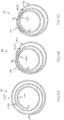
- the spiral spring 1 is configured such that when an elasticity retaining state (the state shown in FIGS. 1B and 1C ) is reached from a free length state (the state shown in FIG. 1A ) by elastic deformation in the diameter-reducing direction, the first movable coil part 20(1) does not come into contact with both the fixed coil part 10, which is radially adjacent on the inside, and the second movable coil part 20(2), which is radially adjacent on the outside, at the same place in the circumferential direction, and comes into contact with only one of the fixed coil part 10 and the second movable coil part 20(2) in a plurality of places that are circumferentially displaced.
- the first movable coil part 20(1) is in contact with only the second movable coil part 20(2) in a first place 25a that is spaced from the starting end at a predetermined angle in the circumferentially outward direction while being radially spaced from the fixed coil part 10, is in contact with only the second movable coil part 20(2) in a second place 25b that is spaced from the first place 25a at a predetermined angle in the circumferentially outward direction while being radially spaced from the fixed coil part 10, and is in contact with only the second movable coil part 20(2) in a third place 25c that is spaced from the second place 25b at a predetermined angle in the circumferentially outward direction while being radially spaced from the fixed coil part 10.
- the first movable coil part 20(1) is, further, in contact with only the fixed coil part 10 in a fourth place 25d that is between the second place 25b and the third place 25c with respect to the circumferential direction while being radially spaced from the second movable coil part 20(2).
- the first movable coil part 20(1) in the elasticity retaining state, is not in contact with both the fixed coil part 10 and the second movable coil part 20(2) in the same place in the circumferential direction, and is in contact with only one of the fixed coil part 10 and the second movable coil part 20(2) in a plurality of places that are circumferentially displaced.
- the spiral spring 1 with this configuration can have a higher natural frequency than conventional spiral springs, and, moreover, can effectively prevent local stress concentration.
- FIGS. 9A to 9C show plan views of a conventional spiral spring 200 in a free length state, an initial torque generating state, and a maximum torque generating state, respectively.
- FIG. 10 shows the relationship between the number of turns and the curvature when the conventional spiral spring 200 is in an initial torque generating state ( FIG. 9B ).
- FIG. 11 shows the relationship between the number of turns and the curvature when the conventional spiral spring 200 is in a maximum torque generating state ( FIG. 9C ).
- the conventional spiral spring 200 is configured such that the radius of curvature is increased at an approximately constant rate from the inner end that is located radially inside toward the outer end that is located radially outside (the radius is increased at an approximately constant rate).
- the entire area in the circumferential direction except at the first circumferential position 205 is not subjected to frictional contact with other radially adjacent coil parts, and thus is an area where elastic deformation can freely occur. Accordingly, the overall natural frequency of the spiral spring is lowered, and resonance is likely to occur.
- the coil part located in the middle with respect to the radial direction (the second coil part 210(2) in the configuration depicted in the drawings) is compressed by the coil part (210(1)) located radially inside and the coil part (210(3)) located radially outside in the first circumferential position 205, and thus there is a problem in that stress is concentrated on the first circumferential position 205 at the time of elastic deformation movement.
- the first movable coil part 20(1) contact only one of the fixed coil part 10 and the second movable coil part 20(2) in a plurality of places 25a, 25b, and 25c that are circumferentially displaced. Accordingly, it is possible to increase the natural frequency and thus effectively prevent resonance.
- the first movable coil part 20(1) is configured so as not to be simultaneously in contact with both the fixed coil part and the second movable coil part in the same place in the circumferential direction. Accordingly, it is possible to effectively prevent stress concentration on a specific location at the time of elastic deformation movement.
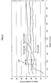
- FIGS. 2 and 3 show the relationship between the number of turns and the curvature when the spiral spring 1 is in an initial torque generating state ( FIG. 1B ) and a maximum torque generating state ( FIG. 1C ), respectively.
- the first movable coil part 20(1) has a plurality of small curvature parts with a smaller radius of curvature than both sides in the circumferential direction.
- the plurality of small curvature parts include first to third small curvature parts 21a to 21c.
- the first small curvature part 21a is provided in a place circumferentially spaced from the terminal end 10b of the fixed coil part 10.
- the second small curvature part 21b is provided in a place circumferentially spaced from the first small curvature part 21a.
- the third small curvature part 21c is provided in a place circumferentially spaced from the second small curvature part 21b.
- a first transitional area 22a and a second transitional area 22b having a larger radius of curvature than the first small curvature part 21a are provided on the starting end side and the terminal end side in the circumferential direction relative to the first small curvature part 21a, respectively.
- the first small curvature part 21a is located between the first and second transitional areas 22a and 22b with respect to the circumferential direction.
- the second small curvature part 21b is located on the terminal end side in the circumferential direction of the second transitional area 22b, and the spiral spring 1 further includes a third transitional area 22c having a larger radius of curvature than the second small curvature part 21b on the terminal end side in the circumferential direction relative to the second small curvature part 21b.
- the second small curvature part 21b is located between the second and third transitional areas 22b and 22c with respect to the circumferential direction.
- the third small curvature part 21c is located on the terminal end side in the circumferential direction of the third transitional area 22c, and the spiral spring 1 further includes a fourth transitional area 22d having a larger radius of curvature than the third small curvature part 21c on the terminal end side in the circumferential direction relative to the third small curvature part 21c.
- the third small curvature part 21c is located between the third and fourth transitional areas 22c and 22d with respect to the circumferential direction.
- the second movable coil part 20(2) includes first to third large curvature parts 23a to 23c in places respectively corresponding to the first to third small curvature parts 21a to 21c with respect to the circumferential direction, and the first to third large curvature parts 23a to 23c each have a larger radius of curvature than both sides in the circumferential direction.
- the first to third small curvature parts 21a to 21c comes into contact with the corresponding first to third large curvature parts 23a to 23c, respectively.
- the first small curvature part 21a comes into contact with the first large curvature part 23a while leaving a gap between the first small curvature part 21a and the fixed coil part 10
- the second small curvature part 21b comes into contact with the second large curvature part 23b while leaving a gap between the second small curvature part 21b and the fixed coil part 10
- the third small curvature part 21c comes into contact with the third large curvature part 23c while leaving a gap between the third small curvature part 21c and the fixed coil part 10.
- the spiral spring 1 includes, on the terminal end side in the circumferential direction relative to the fourth transitional area 22d, a fourth small curvature part 21d having a smaller curvature than the fourth transitional area 22d, a fifth transitional area 22e having a larger curvature than the fourth small curvature part 21d, a fifth small curvature part 21e having a smaller curvature than the fifth transitional area 22e, a sixth transitional area 22f having a larger curvature than the fifth small curvature part 21e, a sixth small curvature part 21f having a smaller curvature than the sixth transitional area 22f, and a seventh transitional area 22g having a larger curvature than the sixth small curvature part 21f, in this order.
- the fifth to seventh transitional areas 22e to 22g serve as the first to third large curvature parts 23a to 23c, respectively.
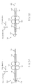
- FIGS. 4A and 4B , FIGS. 5A and 5B , FIGS. 6A and 6B , and FIGS. 7A and 7B show schematic diagrams of steps in the manufacturing method.
- the manufacturing method comprises a spiral forming step of causing the approximately linear elongated member 100 to be engaged with a pressing member 130 that is capable of changing its position, while conveying the elongated member 100 toward one side in a first direction extending along the longitudinal direction by at least one pair of conveying rollers 120, to form a spiral body comprising the fixed coil part 10, the first movable coil part 20(1), and the second movable coil part 20(2) from the linear elongated member 100 ( FIG. 6A ).
- the pressing member 130 is configured to be movable in a second direction that is perpendicular to both the first direction and the rotational shaft direction of the conveying rollers 120.
- the pressing member 130 is disposed so as to be engaged with one side in the second direction of the elongated member 100 in a work area 190 that is located more toward the one side in the first direction than the pair of conveying rollers 120 are, and is configured to be capable of changing the radius of curvature of the spiral body by changing the position of the pressing member 130 in the second direction.
- the pressing member 130 may take various forms as long as it can change the linear elongated member 100 into a spiral shape.
- the pressing member 130 may have a pin-like member that is capable of changing its position in the second direction while being in parallel with the rotational shaft and a roller member that is supported on the pin-like member in a relatively rotatable manner. Due to this configuration, scratches or the like on the surface can be effectively prevented when changing the elongated member 100 from a linear shape into a spiral shape.
- At least one of the pair of conveying rollers 120 includes a rotational speed sensor (not shown) for detecting the rotational speed.
- the spiral forming step is configured to control the position of the pressing member 130 with respect to the second direction, while recognizing what part of the spiral body the part of the elongated member 100 currently engaged with the pressing member 130 will constitute after the spiral body is formed (that is, while recognizing in which coil part of the spiral body said part of the elongated member 100 will be located and where said part of the elongated member 100 will be located in this coil part with respect to the circumferential direction) based on a signal from the rotational speed sensor.
- the pressing member 130 is disposed so as to be engaged with one side of the elongated member 100 with respect to the second direction (that is, the side that will face radially outward after the elongated member 100 is formed into a spiral shape) (see FIG. 6A ), the radius of curvature of the spiral body decreases as the pressing member 130 is moved toward the other side in the second direction, and the radius of curvature of the spiral body increases as the pressing member 130 is moved toward the one side in the second direction.
- guides 140 for guiding the elongated member 100 toward the work area 190 are provided on the downstream side in the conveying direction of the conveying rollers 120 (the one side in the first direction).
- guides 145 for stably guiding the elongated member 100 to the conveying rollers 120 are also provided on the upstream side in the conveying direction of the conveying rollers 120 (the other side in the first direction).
- the manufacturing method according to the present embodiment further comprises a starting end side cutting step performed before the spiral forming step and a terminal end side cutting step performed after the spiral forming step.
- the starting end side cutting step is configured to cut, after the elongated member 100 is conveyed by the pair of conveying rollers 120 such that the tip end side of the elongated member 100 reaches the work area 190 ( FIG. 4A ), the elongated member 100 by a cutting member 150 provided in the work area 190 so as to form the starting end of the spiral spring ( FIG. 4B ).
- the terminal side cutting step is configured to cut off the spiral body from the elongated member 100 by the cutting member 150 disposed in the work area 190 ( FIG. 7B ).
- the terminal end side cutting step performed when manufacturing one spiral spring 1 can be used as the starting end side cutting step performed when manufacturing the next spiral spring 1.
- the spiral spring 1 has the inner end side attachment hook 2a at the inner end (the starting end 10a of the fixed coil part 10) and the outer end side attachment hook 2b at the outer end (the terminal end of the movable coil part 20(2) in the outermost place).
- the manufacturing method further comprises an inner end side attachment hook forming step ( FIG. 5A ) and an outer end side attachment hook forming step ( FIGS. 6B and 7A ).
- the inner end side attachment hook forming step is configured to be performed between the starting end side cutting step ( FIG. 4B ) and the spiral forming step ( FIGS. 5B and 6A ) and cause an inner end side attachment hook forming member 110 disposed in the work area 190 to act on a predetermined site that is continuous with the starting end 10a of the elongated member 100 to form the inner end side attachment hook 2a.
- the inner end side attachment hook forming member has a fixed pin 111 for a hook for engagement with a side of the elongated member 100 that will face radially inward after the spiral body is formed and a movable pin 115 for a hook for engagement with a side of the elongated member 100 that will face radially outward after the spiral body is formed.
- the hook movable pin 115 is moved around the hook fixed pin 111, with the tip end of the elongated member 100 being held between the hook movable pin 115 and the hook fixed pin 111, and thereby, the inner end side attachment hook 2a is formed.
- the outer end side attachment hook forming step is configured to be performed between the spiral forming step ( FIGS. 5B and 6A ) and the terminal end side cutting step ( FIG. 7B ) and cause an outer end side attachment hook forming member 160 disposed in the work area 190 to act on the outer end site of the spiral body formed by the spiral forming step to form the outer end side attachment hook 2b.
- the outer end side attachment hook forming member 160 has a fixed pin 161 for a hook for engagement with a side of the spiral body that will face radially outward and a movable pin 165 for a hook for engagement with a side of the spiral body that will face radially inward.
- the hook movable pin 165 is moved around the hook fixed pin 161, with the elongated member 100 that forms the spiral body being held between the hook movable pin 165 and the hook fixed pin 161, and thereby, the outer end side attachment hook 2a is formed.
- the manufacturing method according to the present embodiment is suitably carried out by using, for example, a manufacturing apparatus including:
- FIGS. 8A and 8B show cross-sectional views taken along the lines VIII(a)-VIII(a) and VIII(b)-VIII(b) in FIG. 6A , respectively.
- the elongated member 100 has a cross-sectional shape that is an approximately rectangular shape with a pair of first sides 101(1) and 101(2) facing each other and a pair of second sides 102(1) facing each other.
- the elongated member 100 in an initial state before being formed into a spiral body by the pressing member 130 has the side 101(2) of the pair of first sides that overlaps a line connecting the corresponding ends of the pair of second sides 102(1) and 102(2) (the side facing radially inward when a spiral body is formed) and the side 101(1) of the pair of first sides that has a convex shape bulging outward relative to a line (the dashed double-dotted line in FIG. 8A ) connecting the corresponding ends of the pair of second sides 102(1) and 102(2) (the side engaged with the pressing member 130 and facing radially outward when a spiral body is formed).
- the elongated member 100 it is possible for the elongated member 100 to have an approximately rectangular cross-sectional shape (see FIG. 8B ) after the elongated member 100 is formed into a spiral body from a linear shape by the pressing member 130.
- the elongated member 100 in an initial state before being formed into the spiral body by the pressing member 130 has the side 101(1) of the pair of first sides that has a convex shape bulging outward relative to a line connecting the corresponding ends of the pair of second sides 102(1) and 102(2) (the side that will face radially outward after the spiral body is formed) (see FIG. 8A ).
- the elongated member 100 it is possible for the elongated member 100 to have an approximately rectangular cross-sectional shape as shown in FIG. 8B ) after the elongated member 100 is formed into a spiral body from a linear shape by the pressing member 130.
Landscapes
- Engineering & Computer Science (AREA)
- Mechanical Engineering (AREA)
- Springs (AREA)
- Wire Processing (AREA)
- Valve Device For Special Equipments (AREA)
Description
- The present invention relates to a method for manufacturing a spiral spring. Such a method is disclosed in
patent literature 2, on which the preamble ofclaim 1 is based. - Spiral springs are widely used in various applications such as a valve timing adjuster for rotationally driving a cam shaft by rotative power inputted from the crankshaft in an internal combustion engine.
- The valve timing adjuster includes a housing operatively connected to the crankshaft and a vane rotor operatively connected to the cam shaft, the internal space of the housing is divided into a retard chamber and an advance chamber by vanes in the vane rotor, and supplying hydraulic oil to one of the retard chamber and the advance chamber and discharging hydraulic oil from the other make it possible to change the rotational phase of the vane rotor relative to the housing.
- The valve timing adjuster further includes a spiral spring for enhancing the startability of an internal combustion engine by retaining the rotational phase of the vane rotor relative to the housing at an intermediate phase between the most retarded position and the most advanced position.
- The spiral spring is interposed between the housing and the vane rotor so as to be capable of biasing the vane rotor toward the intermediate phase on the advance side when the vane rotor is placed more toward the retard side than the intermediate phase is, and thereby the rotational movement of the vane rotor at the start of the internal combustion engine is retained at the intermediate phase so that the startability of the internal combustion engine can be enhanced.
- The spiral spring is a member obtained by spirally winding an elongated wire rod in approximately the same plane and arrives at an elasticity retaining state by the relative circumferential movement of the inner end and the outer end in the diameter-reducing direction.
-
FIGS. 9A to 9C show plan views of a conventional spiral spring. -
FIGS. 9A to 9C show a free length state, an initial torque generating state (a state in which the spiral spring is elastically deformed in the diameter-reducing direction from the free length state so as to generate a predetermined initial torque), and a maximum torque generating state (a state in which the spiral spring is elastically deformed in the diameter-reducing direction from the initial torque generating state so as to generate the maximum torque) of the spiral spring, respectively. - As shown in
FIG. 9A , in a free length state, a conventional spiral spring is configured such that the radius of curvature is increased at an approximately constant rate from the inner end that is located radially inside toward the outer end that is located radially outside (the radius is increased at an approximately constant rate). - As shown in
FIGS. 9B and 9C , when a conventional spiral spring having this configuration is brought into an elasticity retaining state such as the initial torque generating state or the maximum torque generating state, all coil parts ranging from the first coil part in the innermost place to the n-th coil part in the outermost place in the radial direction (the third coil part in the configuration depicted in the drawings) come into contact with other radially adjacent coil parts only in one location that is approximately the same position with respect to the circumferential direction (hereinafter referred to as a first circumferential position). - That is, in the aforementioned conventional spiral spring, the entire areas in the circumferential direction of all coil parts except in the first circumferential position are not subjected to frictional contact with other coil parts that are circumferentially adjacent, and thus are areas where elastic deformation can freely occur. Accordingly, there is a problem in that the overall natural frequency of the spiral spring is low.
- When such a conventional spiral spring is used in, for example, a valve timing adjuster disclosed in
patent literature 1, resonance occurs as the output rotational speed of an internal combustion engine increases and the frequency of vibrations added to the spiral spring nears the natural frequency, thus imposing a large burden on the spiral spring. - Moreover, the coil part located in the middle with respect to the radial direction comes into contact with and is compressed by the coil part that is located radially inside and the coil part that is located radially outside in the first circumferential position, thus stress is concentrated on the first circumferential position at the time of elastic deformation movement, and there is a possibility of this part being damaged.
- Accordingly, a spiral spring is desired that can have an increased natural frequency and can prevent or reduce local stress concentration that occurs at the time of elastic deformation movement.
-
- Patent document 1: Japanese Unexamined Patent Publication No.
2010-180862 - Patent document 2: German Patent Application
DE 24 10 898 A1 - The present invention has been achieved in view of the conventional art described above, and an object thereof is to provide a method for efficiently manufacturing a spiral spring capable of having an increased natural frequency and preventing or reducing local stress concentration at the time of elastic deformation movement.
- In order to achieve the object, the present invention provides a manufacturing method according to
claim 1. - The manufacturing method of spiral spring according to the present invention can efficiently manufacture a spiral spring in which a first movable coil part does not come into contact with both a fixed coil part, which is radially adjacent on the inside, and a second movable coil part, which is radially adjacent on the outside, at the same place in the circumferential direction while coming into contact with only one of the fixed coil part and the second movable coil part in a plurality of places that are circumferentially displaced when the spiral spring is in an elasticity retaining state.
- Preferably, the manufacturing method of spiral spring according to the present invention may further include a starting end side cutting step that is performed before the spiral forming step, cuts the elongated member by a cutting member provided in the work area so as to form the starting end of the spiral spring after the elongated member is conveyed by the pair of conveying rollers such that the tip end side of the elongated member reaches the work area, and recognizes an initial position corresponding to the starting end based on a signal obtained from the rotational speed sensor at this moment, and a terminal end side cutting step performed after the spiral forming step, and cuts off the spiral body from the elongated member by the cutting member disposed in the work area so as to form the spiral spring.
- Preferably, the manufacturing method of spiral spring according to the present invention may further include an inner end side attachment hook forming step that is performed between the starting end side cutting step and the spiral forming step, and causes an inner end side attachment hook forming member disposed in the work area to act on a predetermined site that is continuous with the starting end of the elongated member to form an inner end side attachment hook, and an outer end side attachment hook forming step that is performed between the spiral forming step and the terminal end side cutting step, and causes an outer end side attachment hook forming member disposed in the work area to act on an outer end site of the spiral body formed by the spiral forming step to form an outer end side attachment hook.
- In this case, the terminal end side cutting step is configured to cut a site of the spiral body on a downstream side in the conveying direction of the outer end side attachment hook.
- The elongated member may have a cross-sectional shape that is an approximately rectangular shape with a pair of first sides facing each other and a pair of second sides facing each other.
- In the spiral forming step, the pressing member may be engaged with one first side of the pair of first sides of the elongated member so that the radius of curvature of a site of the spiral body that is being formed by the pressing member decreases as the pressing member is moved toward the other first side from the one first side in the second direction, and the radius of curvature of the site of the spiral body that is being formed by the pressing member increases as the pressing member is moved toward the one first side from the other first side in the second direction.
- In this case, in a state before the elongated member is formed into the spiral body by the pressing member, the one first side preferably has a convex shape bulging outward relative to a line connecting the corresponding ends of the pair of second sides while the other first side is along a line connecting the corresponding ends of the pair of second sides.
-
- [
FIG. 1 ]
FIGS. 1A to 1C are plan views of a spiral spring formed by a manufacturing method of spiral spring according to one embodiment of the present invention, and show a free length state, an initial torque generating state and a maximum torque generating state, respectively. - [
Fig. 2 ]
Fig. 2 is a graph showing a relationship between the number of turns and the curvature when the spiral spring shown inFIGS. 1A to 1C is in an initial torque generating state. - [
Fig. 3 ]
Fig. 3 is a graph showing a relationship between the number of turns and the curvature when the spiral spring shown inFIGS. 1A to 1C is in a maximum torque generating state. - [
Fig. 4 ]
FIGS. 4A and 4B are schematic diagrams of steps in the manufacturing method of spiral spring according to one embodiment of the present invention, and show a state in which an elongated member that is a raw material for the spiral spring is conveyed and a starting end side cutting step, respectively. - [
Fig. 5 ]
FIG. 5A and 5B are schematic diagrams of steps in the manufacturing method of spiral spring according to one embodiment of the present invention, and show an inner end side attachment hook forming step and a part of a spiral forming step, respectively. - [
FIG. 6 ]
FIGS. 6A and 6B are schematic diagrams of steps in the manufacturing method of spiral spring according to one embodiment of the present invention, and shows a part of a spiral forming step and a part of an outer end side attachment hook forming step, respectively. - [
FIG. 7 ]
FIGS. 7A and 7B are schematic diagrams of steps in the manufacturing method of spiral spring according to one embodiment of the present invention, and shows a part of the outer end side attachment hook forming step and a terminal end side cutting step, respectively. - [
FIG. 8 ]
FIGS. 8A and 8B are cross-sectional views taken along the lines VIII(a)-VIII(a) and VIII(b)-VIII(b) inFIG. 6A .FIGS. 8C and 8D are cross-sectional views of a conventional spiral spring that are correspond toFIGS. 8A and 8B , respectively. - [
FIG. 9 ]
FIGS. 9A to 9C are plan views of a conventional spiral spring, and show a free length state, an initial torque generating state and a maximum torque generating state, respectively. - [
FIG. 10 ]
Fig. 10 is a graph showing a relationship between the number of turns and the curvature of the conventional spiral spring shown inFIGS. 9A to 9C at the initial torque generating state. - [
FIG. 11 ]
Fig. 11 is a graph showing a relationship between the number of turns and the curvature of the conventional spiral spring shown inFIGS. 9A to 9C at the maximum torque generating state. - Below, a preferable embodiment of the spiral spring manufacturing method according to the present invention is described with reference to the appended drawings.
- First, the configuration of a
spiral spring 1 manufactured by the manufacturing method according to the present embodiment is described. -
FIGS. 1A to 1C show plan views of thespiral spring 1. -
FIGS. 1A to 1C show a free length state, an initial torque generating state (a state in which thespiral spring 1 is elastically deformed in the diameter-reducing direction from the free length state so as to generate a predetermined initial torque), and a maximum torque generating state (a state in which thespiral spring 1 is elastically deformed in the diameter-reducing direction from the initial torque generating state so as to generate the maximum torque) of thespiral spring 1, respectively. - As shown in
FIGS. 1A to 1C , due to the spiral winding of anelongated member 100 in substantially the same plane, thespiral spring 1 has a fixedcoil part 10 that is in the innermost place in the radial direction and serves as an end coil part, and a plurality ofmovable coil parts 20 that are continuous with the terminal end of the fixedcoil part 10. - The fixed
coil part 10 has oneend 10a on the starting end side that forms the inner end of thespiral spring 1 and theother end 10b that spirally extends from the oneend 10a and forms the terminal end that continues to themovable coil parts 20. - In the configuration depicted in the drawings, the area covering approximately 1.25 turns from the inner end of the
spiral spring 1 serves as the fixedcoil part 10. - At the inner end of the spiral spring 1 (the starting end of the fixed coil part), an inner end
side attachment hook 2a is formed. - The plurality of
movable coil parts 20 have a first movable coil part 20(1) that extends from theterminal end 10b of the fixedcoil part 10 so as to be located radially outside of the fixedcoil part 10, and a second movable coil part 20(2) that extends from the terminal end of the first movable coil part 20(1) so as to be located radially outside of the first movable coil part 20(1). - As shown in
FIGS. 1A to 1C , in thespiral spring 1, the terminal end of the second movable coil part 20(2) forms the outer end of thespiral spring 1, and an outer endside attachment hook 2b is formed at the outer end (the terminal end of the second movable coil part 20(2)). - In the present embodiment, a case where the
spiral spring 1 having two movable coil parts is manufactured is described as an example, but, naturally, the present invention is not limited to this embodiment, and is applicable when manufacturing a spiral spring having three or more movable coil parts. - The
spiral spring 1 is configured such that when an elasticity retaining state (the state shown inFIGS. 1B and 1C ) is reached from a free length state (the state shown inFIG. 1A ) by elastic deformation in the diameter-reducing direction, the first movable coil part 20(1) does not come into contact with both the fixedcoil part 10, which is radially adjacent on the inside, and the second movable coil part 20(2), which is radially adjacent on the outside, at the same place in the circumferential direction, and comes into contact with only one of the fixedcoil part 10 and the second movable coil part 20(2) in a plurality of places that are circumferentially displaced. - Specifically, as shown in
FIGS. 1B and 1C , in the elasticity retaining state, the first movable coil part 20(1) is in contact with only the second movable coil part 20(2) in afirst place 25a that is spaced from the starting end at a predetermined angle in the circumferentially outward direction while being radially spaced from the fixedcoil part 10, is in contact with only the second movable coil part 20(2) in asecond place 25b that is spaced from thefirst place 25a at a predetermined angle in the circumferentially outward direction while being radially spaced from the fixedcoil part 10, and is in contact with only the second movable coil part 20(2) in athird place 25c that is spaced from thesecond place 25b at a predetermined angle in the circumferentially outward direction while being radially spaced from the fixedcoil part 10. - When the
spiral spring 1 is in the elasticity retaining state, the first movable coil part 20(1) is, further, in contact with only the fixedcoil part 10 in afourth place 25d that is between thesecond place 25b and thethird place 25c with respect to the circumferential direction while being radially spaced from the second movable coil part 20(2). - Thus, in the
spiral spring 1, in the elasticity retaining state, the first movable coil part 20(1) is not in contact with both the fixedcoil part 10 and the second movable coil part 20(2) in the same place in the circumferential direction, and is in contact with only one of the fixedcoil part 10 and the second movable coil part 20(2) in a plurality of places that are circumferentially displaced. - The
spiral spring 1 with this configuration can have a higher natural frequency than conventional spiral springs, and, moreover, can effectively prevent local stress concentration. -
FIGS. 9A to 9C show plan views of aconventional spiral spring 200 in a free length state, an initial torque generating state, and a maximum torque generating state, respectively. -
FIG. 10 shows the relationship between the number of turns and the curvature when theconventional spiral spring 200 is in an initial torque generating state (FIG. 9B ). -
FIG. 11 shows the relationship between the number of turns and the curvature when theconventional spiral spring 200 is in a maximum torque generating state (FIG. 9C ). - As shown in
FIG. 9A , in a free length state, theconventional spiral spring 200 is configured such that the radius of curvature is increased at an approximately constant rate from the inner end that is located radially inside toward the outer end that is located radially outside (the radius is increased at an approximately constant rate). - As shown in
FIGS. 9B and 9C , when theconventional spiral spring 200 having this configuration is brought into an elasticity retaining state such as the initial torque generating state or the maximum torque generating state, all coil parts ranging from a first coil part 210 (1) in the innermost place to a third coil part 210(3) in the outermost place in the radial direction come into contact with other radially adjacent coil parts only in one location that is approximately the same position with respect to the circumferential direction (hereinafter referred to as a first circumferential position 205). - In this case, in every one of all coil parts, the entire area in the circumferential direction except at the first
circumferential position 205 is not subjected to frictional contact with other radially adjacent coil parts, and thus is an area where elastic deformation can freely occur. Accordingly, the overall natural frequency of the spiral spring is lowered, and resonance is likely to occur. - Moreover, in the conventional configuration, the coil part located in the middle with respect to the radial direction (the second coil part 210(2) in the configuration depicted in the drawings) is compressed by the coil part (210(1)) located radially inside and the coil part (210(3)) located radially outside in the first
circumferential position 205, and thus there is a problem in that stress is concentrated on the firstcircumferential position 205 at the time of elastic deformation movement. - On the other hand, in the
spiral spring 1, the first movable coil part 20(1) contact only one of the fixedcoil part 10 and the second movable coil part 20(2) in a plurality ofplaces - Moreover, the first movable coil part 20(1) is configured so as not to be simultaneously in contact with both the fixed coil part and the second movable coil part in the same place in the circumferential direction. Accordingly, it is possible to effectively prevent stress concentration on a specific location at the time of elastic deformation movement.
-
FIGS. 2 and3 show the relationship between the number of turns and the curvature when thespiral spring 1 is in an initial torque generating state (FIG. 1B ) and a maximum torque generating state (FIG. 1C ), respectively. - As shown in
FIGS. 1A to 1C andFIGS. 2 and3 , the first movable coil part 20(1) has a plurality of small curvature parts with a smaller radius of curvature than both sides in the circumferential direction. - In the configuration depicted in the drawings, the plurality of small curvature parts include first to third
small curvature parts 21a to 21c. - The first
small curvature part 21a is provided in a place circumferentially spaced from theterminal end 10b of the fixedcoil part 10. - The second
small curvature part 21b is provided in a place circumferentially spaced from the firstsmall curvature part 21a. - The third
small curvature part 21c is provided in a place circumferentially spaced from the secondsmall curvature part 21b. - As shown in
FIGS. 1A to 1C andFIGS. 2 and3 , in thespiral spring 1, a firsttransitional area 22a and a secondtransitional area 22b having a larger radius of curvature than the firstsmall curvature part 21a are provided on the starting end side and the terminal end side in the circumferential direction relative to the firstsmall curvature part 21a, respectively. - That is, the first
small curvature part 21a is located between the first and secondtransitional areas - The second
small curvature part 21b is located on the terminal end side in the circumferential direction of the secondtransitional area 22b, and thespiral spring 1 further includes a thirdtransitional area 22c having a larger radius of curvature than the secondsmall curvature part 21b on the terminal end side in the circumferential direction relative to the secondsmall curvature part 21b. - That is, the second
small curvature part 21b is located between the second and thirdtransitional areas - The third
small curvature part 21c is located on the terminal end side in the circumferential direction of the thirdtransitional area 22c, and thespiral spring 1 further includes a fourthtransitional area 22d having a larger radius of curvature than the thirdsmall curvature part 21c on the terminal end side in the circumferential direction relative to the thirdsmall curvature part 21c. - That is, the third
small curvature part 21c is located between the third and fourthtransitional areas - On the other hand, the second movable coil part 20(2) includes first to third
large curvature parts 23a to 23c in places respectively corresponding to the first to thirdsmall curvature parts 21a to 21c with respect to the circumferential direction, and the first to thirdlarge curvature parts 23a to 23c each have a larger radius of curvature than both sides in the circumferential direction. - In this configuration, the first to third
small curvature parts 21a to 21c comes into contact with the corresponding first to thirdlarge curvature parts 23a to 23c, respectively. - Specifically, the first
small curvature part 21a comes into contact with the firstlarge curvature part 23a while leaving a gap between the firstsmall curvature part 21a and the fixedcoil part 10, the secondsmall curvature part 21b comes into contact with the secondlarge curvature part 23b while leaving a gap between the secondsmall curvature part 21b and the fixedcoil part 10, and the thirdsmall curvature part 21c comes into contact with the thirdlarge curvature part 23c while leaving a gap between the thirdsmall curvature part 21c and the fixedcoil part 10. - As shown in
FIGS. 1A to 1C , thespiral spring 1 includes, on the terminal end side in the circumferential direction relative to the fourthtransitional area 22d, a fourthsmall curvature part 21d having a smaller curvature than the fourthtransitional area 22d, a fifthtransitional area 22e having a larger curvature than the fourthsmall curvature part 21d, a fifthsmall curvature part 21e having a smaller curvature than the fifthtransitional area 22e, a sixthtransitional area 22f having a larger curvature than the fifthsmall curvature part 21e, a sixthsmall curvature part 21f having a smaller curvature than the sixthtransitional area 22f, and a seventhtransitional area 22g having a larger curvature than the sixthsmall curvature part 21f, in this order. - In this configuration, the fifth to seventh
transitional areas 22e to 22g serve as the first to thirdlarge curvature parts 23a to 23c, respectively. - As shown in
FIGS. 1B and 1C , with thespiral spring 1 being in the elasticity retaining state, a portion of the first movable coil part 20(1) halfway between the second and thirdsmall curvature parts coil part 10 while leaving a gap between this portion and the second movable coil part 20(2), and thereby the natural frequency is further increased. - Next, a manufacturing method according to the present embodiment for manufacturing the
spiral spring 1 is described. -
FIGS. 4A and 4B ,FIGS. 5A and 5B ,FIGS. 6A and 6B , andFIGS. 7A and 7B show schematic diagrams of steps in the manufacturing method. - The manufacturing method comprises a spiral forming step of causing the approximately linear
elongated member 100 to be engaged with apressing member 130 that is capable of changing its position, while conveying theelongated member 100 toward one side in a first direction extending along the longitudinal direction by at least one pair of conveyingrollers 120, to form a spiral body comprising the fixedcoil part 10, the first movable coil part 20(1), and the second movable coil part 20(2) from the linear elongated member 100 (FIG. 6A ). - As shown in
FIG. 6A , the pressingmember 130 is configured to be movable in a second direction that is perpendicular to both the first direction and the rotational shaft direction of the conveyingrollers 120. - The pressing
member 130 is disposed so as to be engaged with one side in the second direction of theelongated member 100 in awork area 190 that is located more toward the one side in the first direction than the pair of conveyingrollers 120 are, and is configured to be capable of changing the radius of curvature of the spiral body by changing the position of thepressing member 130 in the second direction. - The pressing
member 130 may take various forms as long as it can change the linearelongated member 100 into a spiral shape. For example, the pressingmember 130 may have a pin-like member that is capable of changing its position in the second direction while being in parallel with the rotational shaft and a roller member that is supported on the pin-like member in a relatively rotatable manner. Due to this configuration, scratches or the like on the surface can be effectively prevented when changing theelongated member 100 from a linear shape into a spiral shape. - Specifically, at least one of the pair of conveying
rollers 120 includes a rotational speed sensor (not shown) for detecting the rotational speed. - The spiral forming step is configured to control the position of the
pressing member 130 with respect to the second direction, while recognizing what part of the spiral body the part of theelongated member 100 currently engaged with thepressing member 130 will constitute after the spiral body is formed (that is, while recognizing in which coil part of the spiral body said part of theelongated member 100 will be located and where said part of theelongated member 100 will be located in this coil part with respect to the circumferential direction) based on a signal from the rotational speed sensor. - Here, as described above, the pressing
member 130 is disposed so as to be engaged with one side of theelongated member 100 with respect to the second direction (that is, the side that will face radially outward after theelongated member 100 is formed into a spiral shape) (seeFIG. 6A ), the radius of curvature of the spiral body decreases as the pressingmember 130 is moved toward the other side in the second direction, and the radius of curvature of the spiral body increases as the pressingmember 130 is moved toward the one side in the second direction. - Preferably, guides 140 for guiding the
elongated member 100 toward thework area 190 are provided on the downstream side in the conveying direction of the conveying rollers 120 (the one side in the first direction). - In the present embodiment, guides 145 for stably guiding the
elongated member 100 to the conveyingrollers 120 are also provided on the upstream side in the conveying direction of the conveying rollers 120 (the other side in the first direction). - The manufacturing method according to the present embodiment further comprises a starting end side cutting step performed before the spiral forming step and a terminal end side cutting step performed after the spiral forming step.
- The starting end side cutting step is configured to cut, after the
elongated member 100 is conveyed by the pair of conveyingrollers 120 such that the tip end side of theelongated member 100 reaches the work area 190 (FIG. 4A ), theelongated member 100 by a cuttingmember 150 provided in thework area 190 so as to form the starting end of the spiral spring (FIG. 4B ). - It is possible to recognize an initial position corresponding to the starting end based on a signal from the rotational speed sensor obtained when the
elongated member 100 is cut by the cuttingmember 150. - The terminal side cutting step is configured to cut off the spiral body from the
elongated member 100 by the cuttingmember 150 disposed in the work area 190 (FIG. 7B ). - In the case of continuously manufacturing a plurality of spiral springs 1 from the
elongated member 100, the terminal end side cutting step performed when manufacturing onespiral spring 1 can be used as the starting end side cutting step performed when manufacturing thenext spiral spring 1. - Naturally, it is possible, instead of this, to configure the terminal end side cutting step performed when manufacturing one
spiral spring 1 and the starting end side cutting step performed when manufacturing thenext spiral spring 1 to be separate procedures. - As described above, the
spiral spring 1 has the inner endside attachment hook 2a at the inner end (the startingend 10a of the fixed coil part 10) and the outer endside attachment hook 2b at the outer end (the terminal end of the movable coil part 20(2) in the outermost place). - Accordingly, the manufacturing method further comprises an inner end side attachment hook forming step (
FIG. 5A ) and an outer end side attachment hook forming step (FIGS. 6B and7A ). - The inner end side attachment hook forming step is configured to be performed between the starting end side cutting step (
FIG. 4B ) and the spiral forming step (FIGS. 5B and6A ) and cause an inner end side attachmenthook forming member 110 disposed in thework area 190 to act on a predetermined site that is continuous with the startingend 10a of theelongated member 100 to form the inner endside attachment hook 2a. - Specifically, as shown in
FIG. 5A , the inner end side attachment hook forming member has a fixedpin 111 for a hook for engagement with a side of theelongated member 100 that will face radially inward after the spiral body is formed and amovable pin 115 for a hook for engagement with a side of theelongated member 100 that will face radially outward after the spiral body is formed. - The hook
movable pin 115 is moved around the hook fixedpin 111, with the tip end of theelongated member 100 being held between the hookmovable pin 115 and the hook fixedpin 111, and thereby, the inner endside attachment hook 2a is formed. - The outer end side attachment hook forming step is configured to be performed between the spiral forming step (
FIGS. 5B and6A ) and the terminal end side cutting step (FIG. 7B ) and cause an outer end side attachmenthook forming member 160 disposed in thework area 190 to act on the outer end site of the spiral body formed by the spiral forming step to form the outer endside attachment hook 2b. - Specifically, as shown in
FIGS. 6B ) and7A , the outer end side attachmenthook forming member 160 has a fixedpin 161 for a hook for engagement with a side of the spiral body that will face radially outward and amovable pin 165 for a hook for engagement with a side of the spiral body that will face radially inward. - The hook
movable pin 165 is moved around the hook fixedpin 161, with theelongated member 100 that forms the spiral body being held between the hookmovable pin 165 and the hook fixedpin 161, and thereby, the outer endside attachment hook 2a is formed. - The manufacturing method according to the present embodiment is suitably carried out by using, for example, a manufacturing apparatus including:
- actuators (not shown) that respectively cause the conveying
rollers 120, the pressingmember 130, the cuttingmember 150, the inner end side attachmenthook forming member 110, and the outer end side attachment hook forming member to operate; and - a control unit (not shown) that accommodates operational programs for the actuators and performs operational control on each actuator based on the operational programs in accordance with a signal from the rotational speed sensor.
-
FIGS. 8A and 8B show cross-sectional views taken along the lines VIII(a)-VIII(a) and VIII(b)-VIII(b) inFIG. 6A , respectively. - As shown in
FIG. 8A , theelongated member 100 has a cross-sectional shape that is an approximately rectangular shape with a pair of first sides 101(1) and 101(2) facing each other and a pair of second sides 102(1) facing each other. - As shown in
FIG. 8A , in the manufacturing method according to the present embodiment, theelongated member 100 in an initial state before being formed into a spiral body by the pressingmember 130 has the side 101(2) of the pair of first sides that overlaps a line connecting the corresponding ends of the pair of second sides 102(1) and 102(2) (the side facing radially inward when a spiral body is formed) and the side 101(1) of the pair of first sides that has a convex shape bulging outward relative to a line (the dashed double-dotted line inFIG. 8A ) connecting the corresponding ends of the pair of second sides 102(1) and 102(2) (the side engaged with thepressing member 130 and facing radially outward when a spiral body is formed). - According to this configuration, it is possible for the
elongated member 100 to have an approximately rectangular cross-sectional shape (seeFIG. 8B ) after theelongated member 100 is formed into a spiral body from a linear shape by the pressingmember 130. - That is, when a spiral body is formed from the linear
elongated member 100 by the pressingmember 130, the side of theelongated member 100 engaged with the pressing member 130 (that is, the side that will face radially outward after the spiral body is formed) is pressed by the pressingmember 130 and thinned. - For example, if an elongated member 100' as shown in
FIG. 8C ) that has an approximately rectangular cross-sectional shape in an initial state before being formed into the spiral body by the pressingmember 130 is used, the side 101(1) that will face radially outward will be depressed into a concave shape as shown inFIG. 8D ) after the formation of the spiral body by the pressingmember 130. - In the present embodiment on the other hand, as described above, the
elongated member 100 in an initial state before being formed into the spiral body by the pressingmember 130 has the side 101(1) of the pair of first sides that has a convex shape bulging outward relative to a line connecting the corresponding ends of the pair of second sides 102(1) and 102(2) (the side that will face radially outward after the spiral body is formed) (seeFIG. 8A ). - According to this configuration, it is possible for the
elongated member 100 to have an approximately rectangular cross-sectional shape as shown inFIG. 8B ) after theelongated member 100 is formed into a spiral body from a linear shape by the pressingmember 130. - Accordingly, it is possible to effectively ensure the area of contact of radially adjacent coil parts.
-
- 1
- spiral spring
- 2a
- inner end side attachment hook
- 2b
- outer end side attachment hook
- 10
- fixed coil part
- 20(1)
- first movable coil part
- 20(2)
- second movable coil part
- 21a to 21c
- first to third small curvature parts
- 23a to 23c
- first to third large curvature parts
- 100
- elongated member
- 101(1), 101(2)
- a pair of first sides
- 102(1), 102(2)
- a pair of second sides
- 120
- conveying roller
- 130
- pressing member
- 150
- cutting member
Claims (4)
- A manufacturing method of spiral spring (1) with a fixed coil part (10) serving as an end coil part and a plurality of movable coil parts (20(1), 20(2)) being continuous with a terminal end of the fixed coil part (10), the fixed coil part (10) and the plurality of movable coil parts (20(1), 20(2) being wound to form the spiral body in substantially the same plane, at least a first movable coil part (20(1)) of the plurality of movable coil parts (20(1), 20(2) that is in the innermost place in the radial direction does not come into contact with both the fixed coil part (10), which is radially adjacent on the inside, and a second movable coil part (20(2)), which is radially adjacent on the outside, at the same place in the circumferential direction while coming into contact with only one of the fixed coil part (10) and the second movable coil part (20(2)) in a plurality of places that are circumferentially displaced when the spiral spring (1) is in an elasticity retaining state reached from a free length state by elastic deformation in the diameter-reducing direction, the manufacturing method of spiral spring (1) comprising,
a spiral forming step of causing an approximately linear elongated member (100) to be conveyed toward one side in a first direction extending along the longitudinal direction of the elongated member (100) by at least one pair of conveying roller (120)s and also to be engaged with a pressing member that is movable in the first direction and a second direction perpendicular to both the first direction and a rotational shaft direction of the conveying roller (120)s and is arranged in a work area on one side in the first direction of the pair of conveying roller (120)s, to form a spiral body including the fixed coil part (10), the first movable coil part (20(1)) and the second movable coil part (20(2)) from the linear elongated member (100), characterized in that the spiral forming step is configured to control the position of the pressing member with respect to the second direction, while recognizing, based on a signal from a rotational speed sensor for detecting the rotational speed of at least one of the pair of conveying roller (120)s, a relationship between a position in the longitudinal direction of the elongated member (100) that is engaged with the pressing member and the position in the circumferential direction after the spiral body is formed, wherein the spiral forming step is configured to form a plurality of small curvature parts (21a, 21b, 21c) at a plurality of positions in the circumferential direction of the first movable coil part (20(1)), and also form a plurality of large curvature parts (23a, 23b, 23c) at a plurality of positions of the second movable coil part (20(2)) that respectively correspond to the plurality of small curvature parts (21a, 21b, 21c) in the circumferential directions, and
wherein the small curvature parts (21a, 21b, 21c) come into contact with the corresponding large curvature parts (23a, 23b, 23c) without coming into contact with the fixed coil part (10). - A manufacturing method of spiral spring (1) according to claim 1, further comprising,
a starting end side cutting step that is performed before the spiral forming step, cuts the elongated member (100) by a cutting member provided in the work area so as to form the starting end of the spiral spring (1) after the elongated member (100) is conveyed by the pair of conveying roller (120)s such that the tip end side of the elongated member (100) reaches the work area, and recognizes an initial position corresponding to the starting end based on a signal obtained from the rotational speed sensor at this moment, and
a terminal end side cutting step performed after the spiral forming step, and cuts off the spiral body from the elongated member (100) by the cutting member disposed in the work area so as to form the spiral spring (1). - A manufacturing method of spiral spring (1) according to claim 2, further comprising,
an inner end side attachment hook (2a) forming step that is performed between the starting end side cutting step and the spiral forming step, and causes an inner end side attachment hook (2a) forming member disposed in the work area to act on a predetermined site that is continuous with the starting end of the elongated member (100) to form an inner end side attachment hook (2a), and
an outer end side attachment hook (2b) forming step that is performed between the spiral forming step and the terminal end side cutting step, and causes an outer end side attachment hook (2b) forming member disposed in the work area to act on an outer end site of the spiral body formed by the spiral forming step to form an outer end side attachment hook (2b), and
wherein the terminal end side cutting step cuts a site of the spiral body on a downstream side in the conveying direction of the outer end side attachment hook (2b). - A manufacturing method of spiral spring (1) according to any one of claims 1 to 3,
wherein the elongated member (100) has a cross-sectional shape that is an approximately rectangular shape with a pair of first sides (101(1), 101(2)) facing each other and a pair of second sides (102(1), 102(2)) facing each other,
wherein, in the spiral forming step, the pressing member is engaged with one first side of the pair of first sides (101(1), 101(2)) of the elongated member (100) so that the radius of curvature of a site of the spiral body that is being formed by the pressing member decreases as the pressing member is moved toward the other first side from the one first side in the second direction, and the radius of curvature of the site of the spiral body that is being formed by the pressing member increases as the pressing member is moved toward the one first side from the other first side in the second direction, and
wherein, in a state before the elongated member (100) is formed into the spiral body by the pressing member, the one first side has a convex shape bulging outward relative to a line connecting the corresponding ends of the pair of second sides (102(1), 102(2)) while the other first side is along a line connecting the corresponding ends of the pair of second sides (102(1), 102(2)).
Applications Claiming Priority (2)
| Application Number | Priority Date | Filing Date | Title |
|---|---|---|---|
| JP2012272912A JP5839714B2 (en) | 2012-12-14 | 2012-12-14 | Method for manufacturing a spring |
| PCT/JP2013/081239 WO2014091891A1 (en) | 2012-12-14 | 2013-11-20 | Spiral spring manufacturing method |
Publications (3)
| Publication Number | Publication Date |
|---|---|
| EP2933036A1 EP2933036A1 (en) | 2015-10-21 |
| EP2933036A4 EP2933036A4 (en) | 2016-03-23 |
| EP2933036B1 true EP2933036B1 (en) | 2018-06-06 |
Family
ID=50934186
Family Applications (1)
| Application Number | Title | Priority Date | Filing Date |
|---|---|---|---|
| EP13863522.2A Active EP2933036B1 (en) | 2012-12-14 | 2013-11-20 | Spiral spring manufacturing method |
Country Status (5)
| Country | Link |
|---|---|
| US (1) | US9782819B2 (en) |
| EP (1) | EP2933036B1 (en) |
| JP (1) | JP5839714B2 (en) |
| CN (1) | CN104822473B (en) |
| WO (1) | WO2014091891A1 (en) |
Families Citing this family (9)
| Publication number | Priority date | Publication date | Assignee | Title |
|---|---|---|---|---|
| JP5661725B2 (en) * | 2012-12-13 | 2015-01-28 | サンコール株式会社 | Mainspring |
| CN105290278B (en) * | 2015-11-13 | 2017-12-29 | 江门市科业机电制造有限公司 | A kind of spiral guard production equipment |
| CN110576091B (en) * | 2018-06-11 | 2021-12-10 | 上海微创投资控股有限公司 | Coil pipe and device for preparing pipe into coil pipe |
| CN111774454A (en) * | 2019-04-03 | 2020-10-16 | 海信(浙江)空调有限公司 | Automatic coiler for copper pipes |
| CN110125631B (en) * | 2019-04-28 | 2021-05-14 | 上海航天设备制造总厂有限公司 | Scroll spring running-in device and method |
| CN111804848A (en) * | 2020-07-28 | 2020-10-23 | 浙江宏鼎实业有限公司 | A kind of forming equipment of scroll spring |
| CN112893696A (en) * | 2021-01-08 | 2021-06-04 | 南京亭上雪科技有限公司 | Steel bar spiral bending device |
| CN118143165A (en) * | 2024-04-07 | 2024-06-07 | 乐清市宁得利弹簧制造有限公司 | A sensor-based spring machine wire feeding wheel structure and control method |
| CN119839410B (en) * | 2025-03-19 | 2025-08-15 | 浙江天境建设集团有限公司 | Steel frame welding device and method for house building |
Family Cites Families (22)
| Publication number | Priority date | Publication date | Assignee | Title |
|---|---|---|---|---|
| US2503149A (en) * | 1942-12-30 | 1950-04-04 | Bonnemort Daniel Emil Augustin | Double spiral spring |
| DE943288C (en) | 1950-04-27 | 1956-05-17 | Willem Johan Bernard Jansen | Method and device for the production of flat spiral springs |
| DE2410898C3 (en) | 1974-03-07 | 1978-03-16 | Feinmetall Gmbh, 7033 Herrenberg | Device for the continuous bending of a metal wire or strip |
| US4184350A (en) * | 1978-06-26 | 1980-01-22 | Sun Chemical Corporation | High-production method and apparatus for making spiral convolution electrical heating coils |
| JPS59199135A (en) * | 1983-04-26 | 1984-11-12 | Morita Tekkosho:Kk | Method and device for forming pigtail for coil spring |
| JPS6318640U (en) * | 1986-07-21 | 1988-02-06 | ||
| JPH0759325B2 (en) * | 1991-09-25 | 1995-06-28 | サンコール株式会社 | Corrugated spring forming device |
| JP3030688B2 (en) * | 1996-01-31 | 2000-04-10 | 旭精機工業株式会社 | Spiral spring forming method |
| JP3328538B2 (en) | 1997-02-03 | 2002-09-24 | 東洋ファイン株式会社 | Method of manufacturing spiral spring |
| US7055244B2 (en) * | 2002-03-14 | 2006-06-06 | Anand Waman Bhagwat | Method of manufacturing flat wire coil springs to improve fatigue life and avoid blue brittleness |
| GR1006845B (en) * | 2003-10-02 | 2010-07-05 | Αναγνωστοπουλος, Αντωνιος Παναγιωτη | Spring-manufacturing method using wire of round or differetntly-shaped calibre |
| JP4536701B2 (en) * | 2006-11-06 | 2010-09-01 | 三菱製鋼株式会社 | Coil spring forming device |
| JP2010527795A (en) * | 2007-05-23 | 2010-08-19 | シパヒオグル,セリック ヤイ ヴェ ヤン ウルンレリ サナイ ヴェ チカレット リミテッド シルケチ | Continuously nested springs and their manufacture |
| JP4949958B2 (en) * | 2007-07-25 | 2012-06-13 | シロキ工業株式会社 | Method and apparatus for manufacturing spiral spring |
| CN101214523A (en) * | 2008-01-01 | 2008-07-09 | 长安汽车(集团)有限责任公司 | An automatic winding method for an extra-long sheath spring |
| JP2009190059A (en) | 2008-02-14 | 2009-08-27 | Shiroki Corp | Method and device for manufacturing spiral spring |
| CH699955A1 (en) * | 2008-11-25 | 2010-05-31 | Remex Ag | Method and apparatus for the production of springs. |
| JP4725655B2 (en) * | 2009-02-09 | 2011-07-13 | 株式会社デンソー | Valve timing adjustment device |
| JP5051267B2 (en) * | 2010-04-26 | 2012-10-17 | 株式会社デンソー | Valve timing adjustment device |
| JP5333544B2 (en) * | 2011-08-08 | 2013-11-06 | 株式会社デンソー | Hydraulic valve timing adjustment device |
| JP5382086B2 (en) * | 2011-10-25 | 2014-01-08 | 株式会社デンソー | Hydraulic valve timing adjustment device |
| JP5661725B2 (en) * | 2012-12-13 | 2015-01-28 | サンコール株式会社 | Mainspring |
-
2012
- 2012-12-14 JP JP2012272912A patent/JP5839714B2/en active Active
-
2013
- 2013-11-20 EP EP13863522.2A patent/EP2933036B1/en active Active
- 2013-11-20 US US14/436,794 patent/US9782819B2/en active Active
- 2013-11-20 CN CN201380061198.8A patent/CN104822473B/en active Active
- 2013-11-20 WO PCT/JP2013/081239 patent/WO2014091891A1/en not_active Ceased
Non-Patent Citations (1)
| Title |
|---|
| None * |
Also Published As
| Publication number | Publication date |
|---|---|
| CN104822473B (en) | 2016-08-24 |
| EP2933036A4 (en) | 2016-03-23 |
| CN104822473A (en) | 2015-08-05 |
| WO2014091891A1 (en) | 2014-06-19 |
| EP2933036A1 (en) | 2015-10-21 |
| US9782819B2 (en) | 2017-10-10 |
| JP5839714B2 (en) | 2016-01-06 |
| JP2014117717A (en) | 2014-06-30 |
| US20160167106A1 (en) | 2016-06-16 |
Similar Documents
| Publication | Publication Date | Title |
|---|---|---|
| US9782819B2 (en) | Spiral spring manufacturing method | |
| US8763573B2 (en) | Camshaft adjusting arrangement | |
| US9780607B2 (en) | Stator core for an electronically commutated direct current motor and method for producing a stator | |
| CN103216287B (en) | Camshaft adjuster | |
| US9249695B2 (en) | Electric phasing of a concentric camshaft | |
| EP2933523B1 (en) | Spiral spring | |
| JP2014114947A (en) | Pulley structure | |
| CN107923511B (en) | Transmission with flexible gear | |
| WO2011035325A3 (en) | Longitudinal canted coil spring contacts to facilitate assembly | |
| JP5333544B2 (en) | Hydraulic valve timing adjustment device | |
| JP5382086B2 (en) | Hydraulic valve timing adjustment device | |
| EP3444498B1 (en) | Coil spring | |
| JP6198546B2 (en) | Camshaft for internal combustion engine | |
| JP5920632B2 (en) | Valve timing adjustment device | |
| EP3786475B1 (en) | Coil spring | |
| US9638074B1 (en) | Dual-lobed cam for a camshaft and engine assembly | |
| JP2019085994A (en) | Valve timing adjustment device | |
| EP3409910B1 (en) | Camshaft and manufacturing method therefor | |
| US10808665B2 (en) | Camshaft for a pump, in particular a high pressure fuel pump, and pump having a camshaft | |
| CN202012434U (en) | Starter one-way part device for starting up or shutting down motor | |
| JP6715844B2 (en) | Method of generating cam profile of cam pack of camshaft and camshaft | |
| KR20160139408A (en) | Compressors with casing treatments in gas turbine engines | |
| JP2010242622A (en) | Variable valve mechanism and internal combustion engine using the same | |
| CN105164378A (en) | Camshaft adjuster |
Legal Events
| Date | Code | Title | Description |
|---|---|---|---|
| PUAI | Public reference made under article 153(3) epc to a published international application that has entered the european phase |
Free format text: ORIGINAL CODE: 0009012 |
|
| 17P | Request for examination filed |
Effective date: 20150416 |
|
| AK | Designated contracting states |
Kind code of ref document: A1 Designated state(s): AL AT BE BG CH CY CZ DE DK EE ES FI FR GB GR HR HU IE IS IT LI LT LU LV MC MK MT NL NO PL PT RO RS SE SI SK SM TR |
|
| AX | Request for extension of the european patent |
Extension state: BA ME |
|
| A4 | Supplementary search report drawn up and despatched |
Effective date: 20160222 |
|
| DAX | Request for extension of the european patent (deleted) | ||
| RIC1 | Information provided on ipc code assigned before grant |
Ipc: F16F 1/10 20060101ALI20160216BHEP Ipc: B21F 3/08 20060101AFI20160216BHEP |
|
| GRAP | Despatch of communication of intention to grant a patent |
Free format text: ORIGINAL CODE: EPIDOSNIGR1 |
|
| STAA | Information on the status of an ep patent application or granted ep patent |
Free format text: STATUS: GRANT OF PATENT IS INTENDED |
|
| INTG | Intention to grant announced |
Effective date: 20180215 |
|
| GRAS | Grant fee paid |
Free format text: ORIGINAL CODE: EPIDOSNIGR3 |
|
| GRAA | (expected) grant |
Free format text: ORIGINAL CODE: 0009210 |
|
| STAA | Information on the status of an ep patent application or granted ep patent |
Free format text: STATUS: THE PATENT HAS BEEN GRANTED |
|
| AK | Designated contracting states |
Kind code of ref document: B1 Designated state(s): AL AT BE BG CH CY CZ DE DK EE ES FI FR GB GR HR HU IE IS IT LI LT LU LV MC MK MT NL NO PL PT RO RS SE SI SK SM TR |
|
| REG | Reference to a national code |
Ref country code: GB Ref legal event code: FG4D |
|
| REG | Reference to a national code |
Ref country code: CH Ref legal event code: EP Ref country code: AT Ref legal event code: REF Ref document number: 1005488 Country of ref document: AT Kind code of ref document: T Effective date: 20180615 |
|
| REG | Reference to a national code |
Ref country code: IE Ref legal event code: FG4D |
|
| REG | Reference to a national code |
Ref country code: DE Ref legal event code: R096 Ref document number: 602013038698 Country of ref document: DE |
|
| REG | Reference to a national code |
Ref country code: NL Ref legal event code: MP Effective date: 20180606 |
|
| REG | Reference to a national code |
Ref country code: LT Ref legal event code: MG4D |
|
| PG25 | Lapsed in a contracting state [announced via postgrant information from national office to epo] |
Ref country code: NO Free format text: LAPSE BECAUSE OF FAILURE TO SUBMIT A TRANSLATION OF THE DESCRIPTION OR TO PAY THE FEE WITHIN THE PRESCRIBED TIME-LIMIT Effective date: 20180906 Ref country code: CY Free format text: LAPSE BECAUSE OF FAILURE TO SUBMIT A TRANSLATION OF THE DESCRIPTION OR TO PAY THE FEE WITHIN THE PRESCRIBED TIME-LIMIT Effective date: 20180606 Ref country code: BG Free format text: LAPSE BECAUSE OF FAILURE TO SUBMIT A TRANSLATION OF THE DESCRIPTION OR TO PAY THE FEE WITHIN THE PRESCRIBED TIME-LIMIT Effective date: 20180906 Ref country code: SE Free format text: LAPSE BECAUSE OF FAILURE TO SUBMIT A TRANSLATION OF THE DESCRIPTION OR TO PAY THE FEE WITHIN THE PRESCRIBED TIME-LIMIT Effective date: 20180606 Ref country code: FI Free format text: LAPSE BECAUSE OF FAILURE TO SUBMIT A TRANSLATION OF THE DESCRIPTION OR TO PAY THE FEE WITHIN THE PRESCRIBED TIME-LIMIT Effective date: 20180606 Ref country code: ES Free format text: LAPSE BECAUSE OF FAILURE TO SUBMIT A TRANSLATION OF THE DESCRIPTION OR TO PAY THE FEE WITHIN THE PRESCRIBED TIME-LIMIT Effective date: 20180606 Ref country code: LT Free format text: LAPSE BECAUSE OF FAILURE TO SUBMIT A TRANSLATION OF THE DESCRIPTION OR TO PAY THE FEE WITHIN THE PRESCRIBED TIME-LIMIT Effective date: 20180606 |
|
| PG25 | Lapsed in a contracting state [announced via postgrant information from national office to epo] |
Ref country code: LV Free format text: LAPSE BECAUSE OF FAILURE TO SUBMIT A TRANSLATION OF THE DESCRIPTION OR TO PAY THE FEE WITHIN THE PRESCRIBED TIME-LIMIT Effective date: 20180606 Ref country code: HR Free format text: LAPSE BECAUSE OF FAILURE TO SUBMIT A TRANSLATION OF THE DESCRIPTION OR TO PAY THE FEE WITHIN THE PRESCRIBED TIME-LIMIT Effective date: 20180606 Ref country code: GR Free format text: LAPSE BECAUSE OF FAILURE TO SUBMIT A TRANSLATION OF THE DESCRIPTION OR TO PAY THE FEE WITHIN THE PRESCRIBED TIME-LIMIT Effective date: 20180907 Ref country code: RS Free format text: LAPSE BECAUSE OF FAILURE TO SUBMIT A TRANSLATION OF THE DESCRIPTION OR TO PAY THE FEE WITHIN THE PRESCRIBED TIME-LIMIT Effective date: 20180606 |
|
| REG | Reference to a national code |
Ref country code: AT Ref legal event code: MK05 Ref document number: 1005488 Country of ref document: AT Kind code of ref document: T Effective date: 20180606 |
|
| PG25 | Lapsed in a contracting state [announced via postgrant information from national office to epo] |
Ref country code: NL Free format text: LAPSE BECAUSE OF FAILURE TO SUBMIT A TRANSLATION OF THE DESCRIPTION OR TO PAY THE FEE WITHIN THE PRESCRIBED TIME-LIMIT Effective date: 20180606 |
|
| PG25 | Lapsed in a contracting state [announced via postgrant information from national office to epo] |
Ref country code: AT Free format text: LAPSE BECAUSE OF FAILURE TO SUBMIT A TRANSLATION OF THE DESCRIPTION OR TO PAY THE FEE WITHIN THE PRESCRIBED TIME-LIMIT Effective date: 20180606 Ref country code: IS Free format text: LAPSE BECAUSE OF FAILURE TO SUBMIT A TRANSLATION OF THE DESCRIPTION OR TO PAY THE FEE WITHIN THE PRESCRIBED TIME-LIMIT Effective date: 20181006 Ref country code: PL Free format text: LAPSE BECAUSE OF FAILURE TO SUBMIT A TRANSLATION OF THE DESCRIPTION OR TO PAY THE FEE WITHIN THE PRESCRIBED TIME-LIMIT Effective date: 20180606 Ref country code: EE Free format text: LAPSE BECAUSE OF FAILURE TO SUBMIT A TRANSLATION OF THE DESCRIPTION OR TO PAY THE FEE WITHIN THE PRESCRIBED TIME-LIMIT Effective date: 20180606 Ref country code: RO Free format text: LAPSE BECAUSE OF FAILURE TO SUBMIT A TRANSLATION OF THE DESCRIPTION OR TO PAY THE FEE WITHIN THE PRESCRIBED TIME-LIMIT Effective date: 20180606 Ref country code: CZ Free format text: LAPSE BECAUSE OF FAILURE TO SUBMIT A TRANSLATION OF THE DESCRIPTION OR TO PAY THE FEE WITHIN THE PRESCRIBED TIME-LIMIT Effective date: 20180606 Ref country code: SK Free format text: LAPSE BECAUSE OF FAILURE TO SUBMIT A TRANSLATION OF THE DESCRIPTION OR TO PAY THE FEE WITHIN THE PRESCRIBED TIME-LIMIT Effective date: 20180606 |
|
| PG25 | Lapsed in a contracting state [announced via postgrant information from national office to epo] |
Ref country code: SM Free format text: LAPSE BECAUSE OF FAILURE TO SUBMIT A TRANSLATION OF THE DESCRIPTION OR TO PAY THE FEE WITHIN THE PRESCRIBED TIME-LIMIT Effective date: 20180606 Ref country code: IT Free format text: LAPSE BECAUSE OF FAILURE TO SUBMIT A TRANSLATION OF THE DESCRIPTION OR TO PAY THE FEE WITHIN THE PRESCRIBED TIME-LIMIT Effective date: 20180606 |
|
| REG | Reference to a national code |
Ref country code: DE Ref legal event code: R097 Ref document number: 602013038698 Country of ref document: DE |
|
| PLBE | No opposition filed within time limit |
Free format text: ORIGINAL CODE: 0009261 |
|
| STAA | Information on the status of an ep patent application or granted ep patent |
Free format text: STATUS: NO OPPOSITION FILED WITHIN TIME LIMIT |
|
| 26N | No opposition filed |
Effective date: 20190307 |
|
| PG25 | Lapsed in a contracting state [announced via postgrant information from national office to epo] |
Ref country code: SI Free format text: LAPSE BECAUSE OF FAILURE TO SUBMIT A TRANSLATION OF THE DESCRIPTION OR TO PAY THE FEE WITHIN THE PRESCRIBED TIME-LIMIT Effective date: 20180606 Ref country code: DK Free format text: LAPSE BECAUSE OF FAILURE TO SUBMIT A TRANSLATION OF THE DESCRIPTION OR TO PAY THE FEE WITHIN THE PRESCRIBED TIME-LIMIT Effective date: 20180606 |
|
| REG | Reference to a national code |
Ref country code: CH Ref legal event code: PL |
|
| GBPC | Gb: european patent ceased through non-payment of renewal fee |
Effective date: 20181120 |
|
| PG25 | Lapsed in a contracting state [announced via postgrant information from national office to epo] |
Ref country code: LU Free format text: LAPSE BECAUSE OF NON-PAYMENT OF DUE FEES Effective date: 20181120 Ref country code: MC Free format text: LAPSE BECAUSE OF FAILURE TO SUBMIT A TRANSLATION OF THE DESCRIPTION OR TO PAY THE FEE WITHIN THE PRESCRIBED TIME-LIMIT Effective date: 20180606 |
|
| REG | Reference to a national code |
Ref country code: BE Ref legal event code: MM Effective date: 20181130 |
|
| REG | Reference to a national code |
Ref country code: IE Ref legal event code: MM4A |
|
| PG25 | Lapsed in a contracting state [announced via postgrant information from national office to epo] |
Ref country code: CH Free format text: LAPSE BECAUSE OF NON-PAYMENT OF DUE FEES Effective date: 20181130 Ref country code: LI Free format text: LAPSE BECAUSE OF NON-PAYMENT OF DUE FEES Effective date: 20181130 |
|
| PG25 | Lapsed in a contracting state [announced via postgrant information from national office to epo] |
Ref country code: IE Free format text: LAPSE BECAUSE OF NON-PAYMENT OF DUE FEES Effective date: 20181120 |
|
| PG25 | Lapsed in a contracting state [announced via postgrant information from national office to epo] |
Ref country code: BE Free format text: LAPSE BECAUSE OF NON-PAYMENT OF DUE FEES Effective date: 20181130 Ref country code: AL Free format text: LAPSE BECAUSE OF FAILURE TO SUBMIT A TRANSLATION OF THE DESCRIPTION OR TO PAY THE FEE WITHIN THE PRESCRIBED TIME-LIMIT Effective date: 20180606 |
|
| PG25 | Lapsed in a contracting state [announced via postgrant information from national office to epo] |
Ref country code: GB Free format text: LAPSE BECAUSE OF NON-PAYMENT OF DUE FEES Effective date: 20181120 |
|
| PG25 | Lapsed in a contracting state [announced via postgrant information from national office to epo] |
Ref country code: MT Free format text: LAPSE BECAUSE OF NON-PAYMENT OF DUE FEES Effective date: 20181120 |
|
| PG25 | Lapsed in a contracting state [announced via postgrant information from national office to epo] |
Ref country code: TR Free format text: LAPSE BECAUSE OF FAILURE TO SUBMIT A TRANSLATION OF THE DESCRIPTION OR TO PAY THE FEE WITHIN THE PRESCRIBED TIME-LIMIT Effective date: 20180606 |
|
| PG25 | Lapsed in a contracting state [announced via postgrant information from national office to epo] |
Ref country code: PT Free format text: LAPSE BECAUSE OF FAILURE TO SUBMIT A TRANSLATION OF THE DESCRIPTION OR TO PAY THE FEE WITHIN THE PRESCRIBED TIME-LIMIT Effective date: 20180606 |
|
| PG25 | Lapsed in a contracting state [announced via postgrant information from national office to epo] |
Ref country code: HU Free format text: LAPSE BECAUSE OF FAILURE TO SUBMIT A TRANSLATION OF THE DESCRIPTION OR TO PAY THE FEE WITHIN THE PRESCRIBED TIME-LIMIT; INVALID AB INITIO Effective date: 20131120 Ref country code: MK Free format text: LAPSE BECAUSE OF NON-PAYMENT OF DUE FEES Effective date: 20180606 |
|
| PGFP | Annual fee paid to national office [announced via postgrant information from national office to epo] |
Ref country code: DE Payment date: 20251128 Year of fee payment: 13 |
|
| PGFP | Annual fee paid to national office [announced via postgrant information from national office to epo] |
Ref country code: FR Payment date: 20251125 Year of fee payment: 13 |